3.3 Relative Accuracy
3.3.1 Relative Accuracy for CO2 and O2 Monitors
The relative accuracy for CO2 and O2 monitors must not exceed 10.0 percent. The relative accuracy test results are also acceptable if the difference between the mean value of the CO2 or O2 monitor measurements and the corresponding reference method measurement mean value, calculated using equation A-7 of this Exhibit, does not exceed +- 1.0 percent CO2 or O2.
 (Equation A-7)
where,
n = Number of data points.
di = The difference between a reference method value and the corresponding continuous emission monitoring system value (RMi–CEMi) at a given point in time i.
3.3.2 Relative Accuracy for Flow Monitors
| (a)
| The relative accuracy of flow monitors must not exceed 10.0 percent at any load (or operating) level at which a RATA is performed (i.e., the low, mid, or high level, as defined in Section 6.5.2.1 of this Exhibit). |
| |
| (b)
| For affected units where the average of the flow reference method measurements of gas velocity at a particular load (or operating) level of the relative accuracy test audit is less than or equal to 10.0 fps, the difference between the mean value of the flow monitor velocity measurements and the reference method mean value in fps at that level must not exceed +- 2.0 fps, wherever the 10.0 percent relative accuracy specification is not achieved. |
| |
3.3.3 Relative Accuracy for Moisture Monitoring Systems
The relative accuracy of a moisture monitoring system must not exceed 10.0 percent. The relative accuracy test results are also acceptable if the difference between the mean value of the reference method measurements (in percent H2O) and the corresponding mean value of the moisture monitoring system measurements (in percent H2O), calculated using Equation A-7 of this Exhibit does not exceed +- 1.5 percent H2O.
3.3.4 Relative Accuracy for Mercury Monitoring Systems
The relative accuracy of a mercury concentration monitoring system or a sorbent trap monitoring system must not exceed 20.0 percent. Alternatively, for affected units where the average of the reference method measurements of mercury concentration during the relative accuracy test audit is less than 5.0 µg/scm, the test results are acceptable if the difference between the mean value of the monitor measurements and the reference method mean value does not exceed 1.0 µg/scm, in cases where the relative accuracy specification of 20.0 percent is not achieved.
3.4 Bias
3.4.1 Flow Monitors
Flow monitors must not be biased low as determined by the test procedure in Section 7.4 of this Exhibit. The bias specification applies to all flow monitors including those measuring an average gas velocity of 10.0 fps or less.
3.4.2 Mercury Monitoring Systems
Mercury concentration monitoring systems and sorbent trap monitoring systems must not be biased low as determined by the test procedure in Section 7.4 of this Exhibit.
The cycle time for mercury concentration monitors, oxygen monitors used to determine percent moisture, and any other monitoring component of a continuous emission monitoring system that is required to perform a cycle time test must not exceed 15 minutes.
4. Data Acquisition and Handling Systems
Automated data acquisition and handling systems must read and record the full range of pollutant concentrations and volumetric flow from zero through span and provide a continuous, permanent record of all measurements and required information as an ASCII flat file capable of transmission both by direct computer-to-computer electronic transfer via modem and EPA-provided software and by an IBM-compatible personal computer diskette. These systems also must have the capability of interpreting and converting the individual output signals from a flow monitor, a CO2 monitor, an O2 monitor, a moisture monitoring system, a mercury concentration monitoring system, and a sorbent trap monitoring system, to produce a continuous readout of pollutant emission rates or pollutant mass emissions (as applicable) in the appropriate units (e.g., lb/hr, lb/MMBtu, ounces/hr, tons/hr). These systems also must have the capability of interpreting and converting the individual output signals from a flow monitor to produce a continuous readout of pollutant mass emission rates in the units of the standard. Where CO2 emissions are measured with a continuous emission monitoring system, the data acquisition and handling system must also produce a readout of CO2 mass emissions in tons.
Data acquisition and handling systems must also compute and record monitor calibration error; any bias adjustments to mercury pollutant concentration data, flow rate data, or mercury emission rate data.
5. Calibration Gas
5.1 Reference Gases
For the purposes of this Appendix, calibration gases include the following:
5.1.1 Standard Reference Materials (SRM)
These calibration gases may be obtained from the National Institute of Standards and Technology (NIST) at the following address: Quince Orchard and Cloppers Road, Gaithersburg, MD 20899-0001.
5.1.2 SRM-Equivalent Compressed Gas Primary Reference Material (PRM)
Contact the Gas Metrology Team, Analytical Chemistry Division, Chemical Science and Technology Laboratory of NIST, at the address in Section 5.1.1, for a list of vendors and cylinder gases.
5.1.3 NIST Traceable Reference Materials
Contact the Gas Metrology Team, Analytical Chemistry Division, Chemical Science and Technology Laboratory of NIST, at the address in Section 5.1.1, for a list of vendors and cylinder gases that meet the definition for a NIST Traceable Reference Material (NTRM) provided in 40 CFR 72.2
, incorporated by reference in Section 225.140.
5.1.4 EPA Protocol Gases
| (a)
| An EPA Protocol Gas is a calibration gas mixture prepared and analyzed according to Section 2 of the "EPA Traceability Protocol for Assay and Certification of Gaseous Calibration Standards," September 1997, EPA-600/R-97/121 or such revised procedure as approved by the Administrator (EPA Traceability Protocol). |
| |
| (b)
| An EPA Protocol Gas must have a specialty gas producer-certified uncertainty (95-percent confidence interval) that must not be greater than 2.0 percent of the certified concentration (tag value) of the gas mixture. The uncertainty must be calculated using the statistical procedures (or equivalent statistical techniques) that are listed in Section 2.1.8 of the EPA Traceability Protocol. |
| |
| (c)
| A copy of EPA-600/R-97/121 is available from the National Technical Information Service, 5285 Port Royal Road, Springfield, VA, 703-605-6585 or http://www.ntis.gov
, and from http://www.epa.gov/ttn/emc/news.html
or http:// www.epa.gov/appcdwww/tsb/index.html
. |
| |
5.1.5 Research Gas Mixtures
Research gas mixtures must be vendor-certified to be within 2.0 percent of the concentration specified on the cylinder label (tag value), using the uncertainty calculation procedure in Section 2.1.8 of the "EPA Traceability Protocol for Assay and Certification of Gaseous Calibration Standards," September 1997, EPA-600/R-97/121. Inquiries about the RGM program should be directed to: National Institute of Standards and Technology, Analytical Chemistry Division, Chemical Science and Technology Laboratory, B-324 Chemistry, Gaithersburg, MD 20899.
5.1.6 Zero Air Material
Zero air material is defined in 40 CFR 72.2
, incorporated by reference in Section 225.140.
5.1.7 NIST/EPA-Approved Certified Reference Materials
Existing certified reference materials (CRMs) that are still within their certification period may be used as calibration gas.
5.1.8 Gas Manufacturer's Intermediate Standards
Gas manufacturer's intermediate standards is defined in 40 CFR 72.2
, incorporated by reference in Section 225.140.
5.1.9 Mercury Standards
For 7-day calibration error tests of mercury concentration monitors and for daily calibration error tests of mercury monitors, either NIST-traceable elemental mercury standards (as defined in Section 225.130) or a NIST-traceable source of oxidized mercury (as defined in Section 225.130) may be used. For linearity checks, NIST-traceable elemental mercury standards must be used. For 3- level and single-point system integrity checks under Section
1.4(c)(1)(E) of this Appendix, Sections 6.2(g) and 6.3.1 of this Exhibit, and Sections 2.1.1, 2.2.1 and 2.6 of Exhibit B to this Appendix, a NIST-traceable source of oxidized mercury must be used. Alternatively, other NIST-traceable standards may be used for the required checks, subject to the approval of the Agency. Notwithstanding these requirements, mercury calibration standards that are not NIST-traceable may be used for the tests described in this Section until December 31, 2009. However, on and after January 1, 2010, only NIST-traceable calibration standards must be used for these tests.
5.2 Concentrations
Four concentration levels are required as follows.
5.2.1 Zero-level Concentration
0.0 to 20.0 percent of span, including span for high-scale or both low- and high-scale for CO2 and O2 monitors, as appropriate.
5.2.2 Low-level Concentration
20.0 to 30.0 percent of span, including span for high-scale or both low- and high-scale for CO2 and O2 monitors, as appropriate.
5.2.3 Mid-level Concentration
50.0 to 60.0 percent of span, including span for high-scale or both low- and high-scale for CO2 and O2 monitors, as appropriate.
5.2.4 High-level Concentration
80.0 to 100.0 percent of span, including span for high-scale or both low-and high-scale for CO2 and O2 monitors, as appropriate.
6. Certification Tests and Procedures
6.1 General Requirements
6.1.1 Pretest Preparation
Install the components of the continuous emission monitoring system (i.e., pollutant concentration monitors, CO2 or O2 monitor, and flow monitor) as specified in Sections 1
, 2
, and 3
of this Exhibit, and prepare each system component and the combined system for operation in accordance with the manufacturer's written instructions. Operate the unit(s) during each period when measurements are made. Units may be tested on non-consecutive days. To the extent practicable, test the DAHS software prior to testing the monitoring hardware.
6.1.2 Requirements for Air Emission Testing Bodies
| (a)
| On and after January 1, 2009, any Air Emission Testing Body (AETB) conducting relative accuracy test audits of CEMS and sorbent trap monitoring systems under Part 225, Subpart B, must conform to the requirements of ASTM D7036-04 (incorporated by reference under Section 225.140). This Section is not applicable to daily operation, daily calibration error checks, daily flow interference checks, quarterly linearity checks or routine maintenance of CEMS. |
| |
| (b)
| The AETB must provide to the affected source(s) certification that the AETB operates in conformance with, and that data submitted to the Agency has been collected in accordance with, the requirements of ASTM D7036-04 (incorporated by reference under Section 225.140). This certification may be provided in the form of: |
| |
| (1)
| A certificate of accreditation of relevant scope issued by a recognized, national accreditation body; or |
| |
| (2)
| A letter of certification signed by a member of the senior management staff of the AETB. |
| |
| (c)
| The AETB must either provide a Qualified Individual on-site to conduct or must oversee all relative accuracy testing carried out by the AETB as required in ASTM D7036-04 (incorporated by reference under Section 225.140). The Qualified Individual must provide the affected source(s) with copies of the qualification credentials relevant to the scope of the testing conducted. |
| |
6.2 Linearity Check (General Procedures)
Check the linearity of each CO2, Hg, and O2 monitor while the unit, or group of units for a common stack, is combusting fuel at conditions of typical stack temperature and pressure; it is not necessary for the unit to be generating electricity during this test. For units with two measurement ranges (high and low) for a particular parameter, perform a linearity check on both the low scale and the high scale. For on-going quality assurance of the CEMS, perform linearity checks, using the procedures in this Section, on the range(s) and at the frequency specified in Section 2.2.1 of Exhibit B to this Appendix. Challenge each monitor with calibration gas, as defined in Section 5.1 of this Exhibit, at the low-, mid-, and high-range concentrations specified in Section 5.2 of this Exhibit. Introduce the calibration gas at the gas injection port, as specified in Section 2.2.1 of this Exhibit. Operate each monitor at its normal operating temperature and conditions. For extractive and dilution type monitors, pass the calibration gas through all filters, scrubbers, conditioners, and other monitor components used during normal sampling and through as much of the sampling probe as is practical. For in-situ type monitors, perform calibration checking all active electronic and optical components, including the transmitter, receiver, and analyzer. Challenge the monitor three times with each reference gas (see example data sheet in Figure 1). Do not use the same gas twice in succession. To the extent practicable, the duration of each linearity test, from the hour of the first injection to the hour of the last injection, must not exceed 24 unit operating hours. Record the monitor response from the data acquisition and handling system. For each concentration, use the average of the responses to determine the error in linearity using Equation A-4 in this Exhibit. Linearity checks are acceptable for monitor or monitoring system certification, recertification, or quality assurance if none of the test results exceed the applicable performance specifications in Section 3.2
of this Exhibit. The status of emission data from a CEMS prior to and during a linearity test period must be determined as follows:
| (a)
| For the initial certification of a CEMS, data from the monitoring system are considered invalid until all certification tests, including the linearity test, have been successfully completed, unless the conditional data validation procedures in Section
1.4(b)(3) of this Appendix are used. When the procedures in Section
1.4(b)(3) of this Appendix are followed, the words "initial certification" apply instead of "recertification," and complete all of the initial certification tests by January 1, 2009, rather than within the time periods specified in Section 1.4(b)(3)(D) of this Appendix for the individual tests. |
| |
| (b)
| For the routine quality assurance linearity checks required by Section 2.2.1 of Exhibit B to this Appendix, use the data validation procedures in Section 2.2.3 of Exhibit B to this Appendix. |
| |
| (c)
| When a linearity test is required as a diagnostic test or for recertification, use the data validation procedures in Section
1.4 (b)(3) of this Appendix. |
| |
| (d)
| For linearity tests of non-redundant backup monitoring systems, use the data validation procedures in Section
1.4(d)(2)(C) of this Appendix. |
| |
| (e)
| For linearity tests performed during a grace period and after the expiration of a grace period, use the data validation procedures in Sections 2.2.3 and 2.2.4, respectively, of Exhibit B to this Appendix. |
| |
| (f)
| For all other linearity checks, use the data validation procedures in Section 2.2.3 of Exhibit B to this Appendix. |
| |
| (g)
| For mercury monitors, follow the guidelines in Section 2.2.3 of this Exhibit in addition to the applicable procedures in Section 6.2 when performing the system integrity checks described in Section
1.4(c)(1)(E) and in Sections 2.1.1, 2.2.1, and 2.6 of Exhibit B to this Appendix. |
| |
| (h)
| For mercury concentration monitors, if moisture is added to the calibration gas during the required linearity checks or system integrity checks, the moisture content of the calibration gas must be accounted for. Under these circumstances, the dry basis concentration of the calibration gas must be used to calculate the linearity error or measurement error (as applicable). |
| |
6.3 7-Day Calibration Error Test
6.3.1 Gas Monitor 7-day Calibration Error Test
Measure the calibration error of each mercury concentration monitor, and each CO2 or O2 monitor while the unit is combusting fuel (but not necessarily generating electricity) once each day for 7 consecutive operating days according to the following procedures. For mercury monitors, you may perform this test using either elemental mercury standards or a NIST-traceable source of oxidized mercury. Also for mercury monitors, if moisture is added to the calibration gas, the added moisture must be accounted for and the dry-basis concentration of the calibration gas must be used to calculate the calibration error. (In the event that unit outages occur after the commencement of the test, the 7 consecutive unit operating days need not be 7 consecutive calendar days.) Units using dual span monitors must perform the calibration error test on both high- and low-scales of the pollutant concentration monitor. The calibration error test procedures in this Section and in Section 6.3.2 of this Exhibit must also be used to perform the daily assessments and additional calibration error tests required under Sections 2.1.1 and 2.1.3 of Exhibit B to this Appendix. Do not make manual or automatic adjustments to the monitor settings until after taking measurements at both zero and high concentration levels for that day during the 7-day test. If automatic adjustments are made following both injections, conduct the calibration error test such that the magnitude of the adjustments can be determined and recorded. Record and report test results for each day using the unadjusted concentration measured in the calibration error test prior to making any manual or automatic adjustments (i.e., resetting the calibration). The calibration error tests should be approximately 24 hours apart, (unless the 7- day test is performed over non-consecutive days). Perform calibration error tests at both the zero-level concentration and high-level concentration, as specified in Section 5.2 of this Exhibit. Alternatively, a mid-level concentration gas (50.0 to 60.0 percent of the span value) may be used in lieu of the high-level gas, provided that the mid-level gas is more representative of the actual stack gas concentrations. Use only calibration gas, as specified in Section 5.1 of this Exhibit. Introduce the calibration gas at the gas injection port, as specified in Section 2.2.1 of this Exhibit. Operate each monitor in its normal sampling mode. For extractive and dilution type monitors, pass the calibration gas through all filters, scrubbers, conditioners, and other monitor components used during normal sampling and through as much of the sampling probe as is practical. For in-situ type monitors, perform calibration, checking all active electronic and optical components, including the transmitter, receiver, and analyzer. Challenge the pollutant concentration monitors and CO2 or O2 monitors once with each calibration gas. Record the monitor response from the data acquisition and handling system. Using Equation A-5 of this Exhibit, determine the calibration error at each concentration once each day (at approximately 24-hour intervals) for 7 consecutive days according to the procedures given in this Section. The results of a 7-day calibration error test are acceptable for monitor or monitoring system certification, recertification or diagnostic testing if none of these daily calibration error test results exceed the applicable performance specifications in Section 3.1
of this Exhibit. The status of emission data from a gas monitor prior to and during a 7-day calibration error test period must be determined as follows:
| (a)
| For initial certification, data from the monitor are considered invalid until all certification tests, including the 7-day calibration error test, have been successfully completed, unless the conditional data validation procedures in Section
1.4(b)(3) of this Appendix are used. When the procedures in Section
1.4(b)(3) of this Appendix are followed, the words "initial certification" apply instead of "recertification," and complete all of the initial certification tests by January 1, 2009, rather than within the time periods specified in Section
1.4(b)(3)(D) of this Appendix for the individual tests. |
| |
| (b)
| When a 7-day calibration error test is required as a diagnostic test or for recertification, use the data validation procedures in Section
1.4(b)(3) of this Appendix. |
| |
6.3.2 Flow Monitor 7-day Calibration Error Test
Flow monitors installed on peaking units (as defined in 40 CFR 72.2
, incorporated by reference in Section 225.140) are exempted from the 7-day calibration error test requirements of this part. In all other cases, perform the 7-day calibration error test of a flow monitor, when required for certification, recertification or diagnostic testing, according to the following procedures. Introduce the reference signal corresponding to the values specified in Section 2.2.2.1 of this Exhibit to the probe tip (or equivalent), or to the transducer. During the 7-day certification test period, conduct the calibration error test while the unit is operating once each unit operating day (as close to 24-hour intervals as practicable). In the event that unit outages occur after the commencement of the test, the 7 consecutive operating days need not be 7 consecutive calendar days. Record the flow monitor responses by means of the data acquisition and handling system. Calculate the calibration error using Equation A-6 of this Exhibit. Do not perform any corrective maintenance, repair, or replacement upon the flow monitor during the 7-day test period other than that required in the quality assurance/quality control plan required by Exhibit B to this Appendix. Do not make adjustments between the zero and high reference level measurements on any day during the 7-day test. If the flow monitor operates within the calibration error performance specification (i.e., less than or equal to 3.0 percent error each day and requiring no corrective maintenance, repair, or replacement during the 7-day test period), the flow monitor passes the calibration error test. Record all maintenance activities and the magnitude of any adjustments. Record output readings from the data acquisition and handling system before and after all adjustments. Record and report all calibration error test results using the unadjusted flow rate measured in the calibration error test prior to resetting the calibration. Record all adjustments made during the 7-day period at the time the adjustment is made, and report them in the certification or recertification application. The status of emissions data from a flow monitor prior to and during a 7-day calibration error test period must be determined as follows:
| (a)
| For initial certification, data from the monitor are considered invalid until all certification tests, including the 7-day calibration error test, have been successfully completed, unless the conditional data validation procedures in Section
1.4(b)(3) of this Appendix are used. When the procedures in Section
1.4(b)(3) of this Appendix are followed, the words "initial certification" apply instead of "recertification," and complete all of the initial certification tests by January 1, 2009, rather than within the time periods specified in Section
1.4(b)(3)(D) of this Appendix for the individual tests. |
| |
| (b)
| When a 7-day calibration error test is required as a diagnostic test or for recertification, use the data validation procedures in Section
1.4(b)(3). |
| |
 (Equation A-6)
where:
CE = Calibration error as a percentage of span.
R = Low or high level reference value specified in Section 2.2.2.1 of this Exhibit.
A = Actual flow monitor response to the reference value.
S = Flow monitor calibration span value as determined under Section 2.1.2.2 of this Exhibit.
6.3.3
For gas or flow monitors installed on peaking units, the exemption from performing the 7-day calibration error test applies as long as the unit continues to meet the definition of a peaking unit in 40 CFR 72.2
, incorporated by reference in Section 225.140. However, if at the end of a particular calendar year or ozone season, it is determined that peaking unit status has been lost, the owner or operator must perform a diagnostic 7-day calibration error test of each monitor installed on the unit, by no later than December 31 of the following calendar year.
6.4 Cycle Time Test
Perform cycle time tests for each pollutant concentration monitor and continuous emission monitoring system while the unit is operating, according to the following procedures. Use a zero-level and a high-level calibration gas (as defined in Section 5.2 of this Exhibit) alternately. For mercury monitors, the calibration gas used for this test may either be the elemental or oxidized form of mercury. To determine the downscale cycle time, measure the concentration of the flue gas emissions until the response stabilizes. Record the stable emissions value. Inject a zero-level concentration calibration gas into the probe tip (or injection port leading to the calibration cell, for in situ systems with no probe). Record the time of the zero gas injection, using the data acquisition and handling system (DAHS). Next, allow the monitor to measure the concentration of the zero gas until the response stabilizes. Record the stable ending calibration gas reading. Determine the downscale cycle time as the time it takes for 95.0 percent of the step change to be achieved between the stable stack emissions value and the stable ending zero gas reading. Then repeat the procedure, starting with stable stack emissions and injecting the high-level gas, to determine the upscale cycle time, which is the time it takes for 95.0 percent of the step change to be achieved between the stable stack emissions value and the stable ending high-level gas reading. Use the following criteria to assess when a stable reading of stack emissions or calibration gas concentration has been attained. A stable value is equivalent to a reading with a change of less than 2.0 percent of the span value for 2 minutes, or a reading with a change of less than 6.0 percent from the measured average concentration over 6 minutes. Alternatively, the reading is considered stable if it changes by no more than 0.5 ppm, 0.5 µg/m3 (for mercury) for two minutes. (Owners or operators of systems which do not record data in 1-minute or 3-minute intervals may petition the Agency for alternative stabilization criteria). For monitors or monitoring systems that perform a series of operations (such as purge, sample, and analyze), time the injections of the calibration gases so they will produce the longest possible cycle time. Refer to Figures 6a and 6b in this Exhibit for example calculations of upscale and downscale cycle times. Report the slower of the two cycle times (upscale or downscale) as the cycle time for the analyzer. On and after January 1, 2009, record the cycle time for each component analyzer separately. For time-shared systems, perform the cycle time tests at each probe locations that will be polled within the same 15-minute period during monitoring system operations. To determine the cycle time for time-shared systems, at each monitoring location, report the sum of the cycle time observed at that monitoring location plus the sum of the time required for all purge cycles (as determined by the continuous emission monitoring system manufacturer) at each of the probe locations of the time-shared systems. For monitors with dual ranges, report the test results for each range separately. Cycle time test results are acceptable for monitor or monitoring system certification, recertification or diagnostic testing if none of the cycle times exceed 15 minutes. The status of emissions data from a monitor prior to and during a cycle time test period must be determined as follows:
| (a)
| For initial certification, data from the monitor are considered invalid until all certification tests, including the cycle time test, have been successfully completed, unless the conditional data validation procedures in Section
1.4(b)(3) of this Appendix are used. When the procedures in Section
1.4(b)(3) of this Appendix are followed, the words "initial certification" apply instead of "recertification," and complete all of the initial certification tests by January 1, 2009, rather than within the time periods specified in Section
1.4(b)(3)(D) of this Appendix for the individual tests. |
| |
| (b)
| When a cycle time test is required as a diagnostic test or for recertification, use the data validation procedures in Section
1.4(b)(3) of this Appendix. |
| |
6.5 Relative Accuracy and Bias Tests (General Procedures)
Perform the required relative accuracy test audits (RATAs) as follows for each flow monitor, each O2 or CO2 diluent monitor used to calculate heat input, each mercury concentration monitoring system, each sorbent trap monitoring system, and each moisture monitoring system:
| (a)
| Except as otherwise provided in this paragraph, perform each RATA while the unit (or units, if more than one unit exhausts into the flue) is combusting the fuel that is a normal primary or backup fuel for that unit (for some units, more than one type of fuel may be considered normal, e.g., a unit that combusts gas or oil on a seasonal basis). For units that co-fire fuels as the predominant mode of operation, perform the RATAs while co-firing. For mercury monitoring systems, perform the RATAs while the unit is combusting coal. When relative accuracy test audits are performed on CEMS installed on bypass stacks/ducts, use the fuel normally combusted by the unit (or units, if more than one unit exhausts into the flue) when emissions exhaust through the bypass stack/ducts. |
| |
| (b)
| Perform each RATA at the load (or operating) level(s) specified in Section 6.5.1 or 6.5.2 of this Exhibit or in Section 2.3.1.3 of Exhibit B to this Appendix, as applicable. |
| |
| (c)
| For monitoring systems with dual ranges, perform the relative accuracy test on the range normally used for measuring emissions. For units with add-on mercury controls that operate continuously rather than seasonally, or for units that need a dual range to record high concentration "spikes" during startup conditions, the low range is considered normal. However, for some dual span units (e.g., for units that use fuel switching or for which the emission controls are operated seasonally), provided that both monitor ranges are connected to a common probe and sample interface, either of the two measurement ranges may be considered normal; in such cases, perform the RATA on the range that is in use at the time of the scheduled test. If the low and high measurement ranges are connected to separate sample probes and interfaces, RATA testing on both ranges is required. |
| |
| (d)
| Record monitor or monitoring system output from the data acquisition and handling system. |
| |
| (e)
| Complete each single-load relative accuracy test audit within a period of 168 consecutive unit operating hours, as defined in 40 CFR 72.2
, incorporated by reference in Section 225.140 (or, for CEMS installed on common stacks or bypass stacks, 168 consecutive stack operating hours, as defined in 40 CFR 72.2
, incorporated by reference in Section 225.140). Notwithstanding this requirement, up to 336 consecutive unit or stack operating hours may be taken to complete the RATA of a mercury monitoring system, when ASTM 6784-02 (incorporated by reference under Section 225.140) or Method 29 in appendix A-8 to 40 CFR 60, incorporated by reference in Section 225.140, is used as the reference method. For 2-level and 3-level flow monitor RATAs, complete all of the RATAs at all levels, to the extent practicable, within a period of 168 consecutive unit (or stack) operating hours; however, if this is not possible, up to 720 consecutive unit (or stack) operating hours may be taken to complete a multiple-load flow RATA. |
| |
| (f)
| The status of emission data from the CEMS prior to and during the RATA test period must be determined as follows: |
| |
| (1)
| For the initial certification of a CEMS, data from the monitoring system are considered invalid until all certification tests, including the RATA, have been successfully completed, unless the conditional data validation procedures in Section
1.4(b)(3) of this Appendix are used. When the procedures in Section
1.4(b)(3) of this Appendix are followed, the words "initial certification" apply instead of "recertification," and complete all of the initial certification tests by January 1, 2009, rather than within the time periods specified in Section
1.4(b)(3)(D) of this Appendix for the individual tests. |
| |
| (2)
| For the routine quality assurance RATAs required by Section 2.3.1 of Exhibit B to this Appendix, use the data validation procedures in Section 2.3.2 of Exhibit B to this Appendix. |
| |
| (3)
| For recertification RATAs, use the data validation procedures in Section
1.4(b)(3). |
| |
| (4)
| For quality assurance RATAs of non-redundant backup monitoring systems, use the data validation procedures in Sections
1.4(d)(2)(D) and (E) of this Appendix. |
| |
| (5)
| For RATAs performed during and after the expiration of a grace period, use the data validation procedures in Sections 2.3.2 and 2.3.3, respectively, of Exhibit B to this Appendix. |
| |
| (6)
| For all other RATAs, use the data validation procedures in Section 2.3.2 of Exhibit B to this Appendix. |
| |
| (g)
| For each flow monitor, each CO2 or O2 diluent monitor used to determine heat input, each moisture monitoring system, each mercury concentration monitoring system, and each sorbent trap monitoring system, calculate the relative accuracy, in accordance with Section 7.3 of this Exhibit, as applicable. |
| |
6.5.1 Gas and Mercury Monitoring System RATAs (Special Considerations)
| (a)
| Perform the required relative accuracy test audits for each CO2 or O2 diluent monitor used to determine heat input, each mercury concentration monitoring system, and each sorbent trap monitoring system at the normal load level or normal operating level for the unit (or combined units, if common stack), as defined in Section 6.5.2.1 of this Exhibit. If two load levels or operating levels have been designated as normal, the RATAs may be done at either load level. |
| |
| (b)
| For the initial certification of a gas or mercury monitoring system and for recertifications in which, in addition to a RATA, one or more other tests are required (i.e., a linearity test, cycle time test, or 7-day calibration error test), the Agency recommends that the RATA not be commenced until the other required tests of the CEMS have been passed. |
| |
6.5.2 Flow Monitor RATAs (Special Considerations)
| (a)
| Except as otherwise provided in paragraph (b) or (e) of this Section, perform relative accuracy test audits for the initial certification of each flow monitor at three different exhaust gas velocities (low, mid, and high), corresponding to three different load levels or operating levels within the range of operation, as defined in Section 6.5.2.1 of this Exhibit. For a common stack/duct, the three different exhaust gas velocities may be obtained from frequently used unit/load or operating level combinations for the units exhausting to the common stack. Select the three exhaust gas velocities such that the audit points at adjacent load or operating levels (i.e., low and mid or mid and high), in megawatts (or in thousands of lb/hr of steam production or in ft/sec, as applicable), are separated by no less than 25.0 percent of the range of operation, as defined in Section 6.5.2.1 of this Exhibit. |
| |
| (b)
| For flow monitors on bypass stacks/ducts and peaking units, the flow monitor relative accuracy test audits for initial certification and recertification must be single-load tests, performed at the normal load, as defined in Section 6.5.2.1(d) of this Exhibit. |
| |
| (c)
| Flow monitor recertification RATAs must be done at three load level(s) (or three operating levels), unless otherwise specified in paragraph (b) or (e) of this Section or unless otherwise specified or approved by the Agency. |
| |
| (d)
| The semiannual and annual quality assurance flow monitor RATAs required under Exhibit B to this Appendix must be done at the load level(s) (or operating levels) specified in Section 2.3.1.3 of Exhibit B to this Appendix. |
| |
| (e)
| For flow monitors installed on units that do not produce electrical or thermal output, the flow RATAs for initial certification or recertification may be done at fewer than three operating levels, if: |
| |
| (1)
| The owner or operator provides a technical justification in the hardcopy portion of the monitoring plan for the unit required under 40 CFR 75.53
(e)(2), incorporated by reference in Section 225.140, demonstrating that the unit operates at only one level or two levels during normal operation (excluding unit startup and shutdown). Appropriate documentation and data must be provided to support the claim of single-level or two-level operation; and |
| |
| (2)
| The justification provided in paragraph (e)(1) of this Section is deemed to be acceptable by the permitting authority. |
| |
6.5.2.1 Range of Operation and Normal Load (or Operating) Level(s)
| (a)
| The owner or operator must determine the upper and lower boundaries of the "range of operation" as follows for each unit (or combination of units, for common stack configurations): |
| |
| (1)
| For affected units that produce electrical output (in megawatts) or thermal output (in klb/hr of steam production or mmBtu/hr), the lower boundary of the range of operation of a unit must be the minimum safe, stable loads for any of the units discharging through the stack. Alternatively, for a group of frequently-operated units that serve a common stack, the sum of the minimum safe, stable loads for the individual units may be used as the lower boundary of the range of operation. The upper boundary of the range of operation of a unit must be the maximum sustainable load. The "maximum sustainable load" is the higher of either: the nameplate or rated capacity of the unit, less any physical or regulatory limitations or other deratings; or the highest sustainable load, based on at least four quarters of representative historical operating data. For common stacks, the maximum sustainable load is the sum of all of the maximum sustainable loads of the individual units discharging through the stack, unless this load is unattainable in practice, in which case use the highest sustainable combined load for the units that discharge through the stack. Based on at least four quarters of representative historical operating data. The load values for the unit(s) must be expressed either in units of megawatts of thousands of lb/hr of steam load or mmBtu/hr of thermal output; or |
| |
| (2)
| For affected units that do not produce electrical or thermal output, the lower boundary of the range of operation must be the minimum expected flue gas velocity (in ft/sec) during normal, stable operation of the unit. The upper boundary of the range of operation must be the maximum potential flue gas velocity (in ft/sec) as defined in Section 2.1.2.1 of this Exhibit. The minimum expected and maximum potential velocities may be derived from the results of reference method testing or by using Equation A-3a or A-3b (as applicable) in Section 2.1.2.1 of this Exhibit. If Equation A-3a or A-3b is used to determine the minimum expected velocity, replace the word "maximum" with the word "minimum" in the definitions of "MPV," "Hf," " ," and ," and  ," and replace the word "minimum" with the word "maximum" in the definition of "CO2d." Alternatively, 0.0 ft/sec may be used as the lower boundary of the range of operation. ," and replace the word "minimum" with the word "maximum" in the definition of "CO2d." Alternatively, 0.0 ft/sec may be used as the lower boundary of the range of operation. |
| |
| (b)
| The operating levels for relative accuracy test audits will, except for peaking units, be defined as follows: the "low" operating level will be the first 30.0 percent of the range of operation; the "mid" operating level will be the middle portion (>30.0 percent, but <=60.0 percent) of the range of operation; and the "high" operating level will be the upper end (>60.0 percent) of the range of operation. For example, if the upper and lower boundaries of the range of operation are 100 and 1100 megawatts, respectively, then the low, mid, and high operating levels would be 100 to 400 megawatts, 400 to 700 megawatts, and 700 to 1100 megawatts, respectively. |
| |
| (c)
| Units that do not produce electrical or thermal output are exempted from the requirements of this paragraph, (c). The owner or operator must identify, for each affected unit or common stack, the "normal" load level or levels (low, mid or high), based on the operating history of the unit(s). To identify the normal load level(s), the owner or operator must, at a minimum, determine the relative number of operating hours at each of the three load levels, low, mid and high over the past four representative operating quarters. The owner or operator must determine, to the nearest 0.1 percent, the percentage of the time that each load level (low, mid, high) has been used during that time period. A summary of the data used for this determination and the calculated results must be kept on-site in a format suitable for inspection. For new units or newly-affected units, the data analysis in this paragraph may be based on fewer than four quarters of data if fewer than four representative quarters of historical load data are available. Or, if no historical load data are available, the owner or operator may designate the normal load based on the expected or projected manner of operating the unit. However, in either case, once four quarters of representative data become available, the historical load analysis must be repeated. |
| |
| (d)
| Determination of normal load (or operating level) |
| |
| (1)
| Based on the analysis of the historical load data described in paragraph (c) of this Section, the owner or operator must, for units that produce electrical or thermal output, designate the most frequently used load level as the normal load level for the unit (or combination of units, for common stacks). The owner or operator may also designate the second most frequently used load level as an additional normal load level for the unit or stack. If the manner of operation of the unit changes significantly, such that the designated normal load(s) or the two most frequently used load levels change, the owner or operator must repeat the historical load analysis and must redesignate the normal load(s) and the two most frequently used load levels, as appropriate. A minimum of two representative quarters of historical load data are required to document that a change in the manner of unit operation has occurred. Update the electronic monitoring plan whenever the normal load level(s) and the two most frequently-used load levels are redesignated. |
| |
| (2)
| For units that do not produce electrical or thermal output, the normal operating level(s) must be determined using sound engineering judgment, based on knowledge of the unit and operating experience with the industrial process. |
| |
| (e)
| The owner or operator must report the upper and lower boundaries of the range of operation for each unit (or combination of units, for common stacks), in units of megawatts or thousands of lb/hr or mmBtu/hr of steam production or ft/sec (as applicable), in the electronic monitoring plan required under Section
1.10 of this Appendix. |
| |
6.5.2.2 Multi-Load (or Multi-Level) Flow RATA Results
For each multi-load (or multi-level) flow RATA, calculate the flow monitor relative accuracy at each operating level. If a flow monitor relative accuracy test is failed or aborted due to a problem with the monitor on any level of a 2-level (or 3-level) relative accuracy test audit, the RATA must be repeated at that load (or operating) level. However, the entire 2-level (or 3-level) relative accuracy test audit does not have to be repeated unless the flow monitor polynomial coefficients or K-factor(s) are changed, in which case a 3- level RATA is required (or, a 2-level RATA, for units demonstrated to operate at only two levels, under Section 6.5.2(e) of this Exhibit).
6.5.3 Calculations
Using the data from the relative accuracy test audits, calculate relative accuracy and bias in accordance with the procedures and equations specified in Section 7
of this Exhibit.
6.5.4 Reference Method Measurement Location
Select a location for reference method measurements that is (1) accessible; (2) in the same proximity as the monitor or monitoring system location; and (3) meets the requirements of Performance Specification 3 in appendix B of 40 CFR 60, incorporated by reference in Section 225.140, for CO2 or O2 monitors, or Method 1 (or 1A) in appendix A of 40 CFR 60, incorporated by reference in Section 225.140, for volumetric flow, except as otherwise indicated in this Section or as approved by the Agency.
6.5.5 Reference Method Traverse Point Selection
Select traverse points that ensure acquisition of representative samples of pollutant and diluent concentrations, moisture content, temperature, and flue gas flow rate over the flue cross Section. To achieve this, the reference method traverse points must meet the requirements of Section 8.1.3 of Performance Specification 2 ("PS No. 2") in appendix B to 40 CFR 60, incorporated by reference in Section 225.140 (for moisture monitoring system RATAs), Performance Specification 3 in appendix B to 40 CFR 60, incorporated by reference in Section 225.140 (for O2 and CO2 monitor RATAs), Method 1 (or 1A) (for volumetric flow rate monitor RATAs), Method 3 (for molecular weight), and Method 4 (for moisture determination) in appendix A to 40 CFR 60, incorporated by reference in Section 225.140. The following alternative reference method traverse point locations are permitted for moisture and gas monitor RATAs:
| (a)
| For moisture determinations where the moisture data are used only to determine stack gas molecular weight, a single reference method point, located at least 1.0 meter from the stack wall, may be used. For moisture monitoring system RATAs and for gas monitor RATAs in which moisture data are used to correct pollutant or diluent concentrations from a dry basis to a wet basis (or vice-versa), single-point moisture sampling may only be used if the 12-point stratification test described in Section 6.5.5.1 of this Exhibit is performed prior to the RATA for at least one pollutant or diluent gas, and if the test is passed according to the acceptance criteria in Section 6.5.5.3(b) of this Exhibit. |
| |
| (b)
| For gas monitoring system RATAs, the owner or operator may use any of the following options: |
| |
| (1)
| At any location (including locations where stratification is expected), use a minimum of six traverse points along a diameter, in the direction of any expected stratification. The points must be located in accordance with Method 1 in appendix A to 40 CFR 60, incorporated by reference in Section 225.140. |
| |
| (2)
| At locations where Section 8.1.3 of PS No. 2 allows the use of a short reference method measurement line (with three points located at 0.4, 1.2, and 2.0 meters from the stack wall), the owner or operator may use an alternative 3-point measurement line, locating the three points at 4.4, 14.6, and 29.6 percent of the way across the stack, in accordance with Method 1 in appendix A to 40 CFR 60, incorporated by reference in Section 225.140. |
| |
| (3)
| At locations where stratification is likely to occur (e.g., following a wet scrubber or when dissimilar gas streams are combined), the short measurement line from Section 8.1.3 of PS No. 2 (or the alternative line described in paragraph (b)(2) of this Section) may be used in lieu of the prescribed "long" measurement line in Section 8.1.3 of PS No. 2, provided that the 12-point stratification test described in Section 6.5.5.1 of this Exhibit is performed and passed one time at the location (according to the acceptance criteria of Section 6.5.5.3(a) of this Exhibit) and provided that either the 12-point stratification test or the alternative (abbreviated) stratification test in Section 6.5.5.2 of this Exhibit is performed and passed prior to each subsequent RATA at the location (according to the acceptance criteria of Section 6.5.5.3(a) of this Exhibit). |
| |
| (4)
| A single reference method measurement point, located no less than 1.0 meter from the stack wall and situated along one of the measurement lines used for the stratification test, may be used at any sampling location if the 12-point stratification test described in Section 6.5.5.1 of this Exhibit is performed and passed prior to each RATA at the location (according to the acceptance criteria of Section 6.5.5.3(b) of this Exhibit). |
| |
| (c)
| For mercury monitoring systems, use the same basic approach for traverse point selection that is used for the other gas monitoring system RATAs, except that the stratification test provisions in Sections 8.1.3 through 8.1.3.5 of Method 30A must apply, rather than the provisions of Sections 6.5.5.1 through 6.5.5.3 of this Exhibit. |
| |
6.5.5.1 Stratification Test
| (a)
| With the unit(s) operating under steady-state conditions at the normal load level (or normal operating level), as defined in Section 6.5.2.1 of this Exhibit, use a traversing gas sampling probe to measure diluent (CO2 or O2) concentrations at a minimum of twelve (12) points, located according to Method 1 in appendix A to 40 CFR 60, incorporated by reference in Section 225.140. |
| |
| (b)
| Use Method 3A in appendix A to 40 CFR 60, incorporated by reference in Section 225.140, to make the measurements. Data from the reference method analyzers must be quality assured by performing analyzer calibration error and system bias checks before the series of measurements and by conducting system bias and calibration drift checks after the measurements, in accordance with the procedures of Method 3A. |
| |
| (c)
| Measure for a minimum of 2 minutes at each traverse point. To the extent practicable, complete the traverse within a 2-hour period. |
| |
| (d)
| If the load has remained constant (+-3.0 percent) during the traverse and if the reference method analyzers have passed all of the required quality assurance checks, proceed with the data analysis. |
| |
| (e)
| Calculate the average CO2 (or O2) concentrations at each of the individual traverse points. Then, calculate the arithmetic average CO2 (or O2) concentrations for all traverse points. |
| |
6.5.5.2 Alternative (Abbreviated) Stratification Test
| (a)
| With the unit(s) operating under steady-state conditions at the normal load level (or normal operating level), as defined in Section 6.5.2.1 of this Exhibit, use a traversing gas sampling probe to measure the diluent (CO2 or O2) concentrations at three points. The points must be located according to the specifications for the long measurement line in Section 8.1.3 of PS No. 2 (i.e., locate the points 16.7 percent, 50.0 percent, and 83.3 percent of the way across the stack). Alternatively, the concentration measurements may be made at six traverse points along a diameter. The six points must be located in accordance with Method 1 in appendix A to 40 CFR 60, incorporated by reference in Section 225.140. |
| |
| (b)
| Use Method 3A in appendix A to 40 CFR 60, incorporated by reference in Section 225.140, to make the measurements. Data from the reference method analyzers must be quality assured by performing analyzer calibration error and system bias checks before the series of measurements and by conducting system bias and calibration drift checks after the measurements, in accordance with the procedures of Method 3A. |
| |
| (c)
| Measure for a minimum of 2 minutes at each traverse point. To the extent practicable, complete the traverse within a 1-hour period. |
| |
| (d)
| If the load has remained constant (+-3.0 percent) during the traverse and if the reference method analyzers have passed all of the required quality assurance checks, proceed with the data analysis. |
| |
| (e)
| Calculate the average CO2 (or O2) concentrations at each of the individual traverse points. Then, calculate the arithmetic average CO2 (or O2) concentrations for all traverse points. |
| |
6.5.5.3 Stratification Test Results and Acceptance Criteria
| (a)
| For each diluent gas, the short reference method measurement line described in Section 8.1.3 of PS No. 2 may be used in lieu of the long measurement line prescribed in Section 8.1.3 of PS No. 2 if the results of a stratification test, conducted in accordance with Section 6.5.5.1 or 6.5.5.2 of this Exhibit (as appropriate; see Section 6.5.5(b)(3) of this Exhibit), show that the concentration at each individual traverse point differs by no more than +-10.0 percent from the arithmetic average concentration for all traverse points. The results are also acceptable if the concentration at each individual traverse point differs by no more than +-5ppm or +-0.5 percent CO2 (or O2) from the arithmetic average concentration for all traverse points. |
| |
| (b)
| For each diluent gas, a single reference method measurement point, located at least 1.0 meter from the stack wall and situated along one of the measurement lines used for the stratification test, may be used for that diluent gas if the results of a stratification test, conducted in accordance with Section 6.5.5.1 of this Exhibit, show that the concentration at each individual traverse point differs by no more than +-5.0 percent from the arithmetic average concentration for all traverse points. The results are also acceptable if the concentration at each individual traverse point differs by no more than +-3 ppm or +-0.3 percent CO2 (or O2) from the arithmetic average concentration for all traverse points. |
| |
| (c)
| The owner or operator must keep the results of all stratification tests on-site, in a format suitable for inspection, as part of the supplementary RATA records required under Section 1.13(a)
(7) of this Appendix. |
| |
6.5.6 Sampling Strategy
| (a)
| Conduct the reference method tests so they will yield results representative of the pollutant concentration, emission rate, moisture, temperature, and flue gas flow rate from the unit and can be correlated with the pollutant concentration monitor, CO2 or O2 monitor, flow monitor, and mercury CEMS measurements. The minimum acceptable time for a gas monitoring system RATA run or for a moisture monitoring system RATA run is 21 minutes. For each run of a gas monitoring system RATA, all necessary pollutant concentration measurements, diluent concentration measurements, and moisture measurements (if applicable) must, to the extent practicable, be made within a 60-minute period. For flow monitor RATAs, the minimum time per run must be 5 minutes. Flow rate reference method measurements may be made either sequentially from port to port or simultaneously at two or more sample ports. The velocity measurement probe may be moved from traverse point to traverse point either manually or automatically. If, during a flow RATA, significant pulsations in the reference method readings are observed, be sure to allow enough measurement time at each traverse point to obtain an accurate average reading when a manual readout method is used (e.g., a "sight-weighted" average from a manometer). Also, allow sufficient measurement time to ensure that stable temperature readings are obtained at each traverse point, particularly at the first measurement point at each sample port, when a probe is moved sequentially from port-to-port. A minimum of one set of auxiliary measurements for stack gas molecular weight determination (i.e., diluent gas data and moisture data) is required for every clock hour of a flow RATA or for every three test runs (whichever is less restrictive). Alternatively, moisture measurements for molecular weight determination may be performed before and after a series of flow RATA runs at a particular load level (low, mid, or high), provided that the time interval between the two moisture measurements does not exceed three hours. If this option is selected, the results of the two moisture determinations must be averaged arithmetically and applied to all RATA runs in the series. Successive flow RATA runs may be performed without waiting in-between runs. If an O2-diluent monitor is used as a CO2 continuous emission monitoring system, perform a CO2 system RATA (i.e., measure CO2, rather than O2, with the reference method). For moisture monitoring systems, an appropriate coefficient, "K" factor or other suitable mathematical algorithm may be developed prior to the RATA, to adjust the monitoring system readings with respect to the reference method. If such a coefficient, K-factor or algorithm is developed, it must be applied to the CEMS readings during the RATA and (if the RATA is passed), to the subsequent CEMS data, by means of the automated data acquisition and handling system. The owner or operator must keep records of the current coefficient, K factor or algorithm, as specified in Section 1.13(a)
(5)(F) of this Appendix. Whenever the coefficient, K factor or algorithm is changed, a RATA of the moisture monitoring system is required. For the RATA of a mercury CEMS using the Ontario Hydro Method, or for the RATA of a sorbent trap system (irrespective of the reference method used), the time per run must be long enough to collect a sufficient mass of mercury to analyze. For the RATA of a sorbent trap monitoring system, the type of sorbent material used by the traps must be the same as for daily operation of the monitoring system; however, the size of the traps used for the RATA may be smaller than the traps used for daily operation of the system. Spike the third section of each sorbent trap with elemental mercury, as described in Section 7.1.2 of Exhibit D to this Appendix. Install a new pair of sorbent traps prior to each test run. For each run, the sorbent trap data must be validated according to the quality assurance criteria in Section 8
of Exhibit D to this Appendix. |
| |
| (b)
| To properly correlate individual mercury CEMS data (in lb/MMBtu) and volumetric flow rate data with the reference method data, annotate the beginning and end of each reference method test run (including the exact time of day) on the individual chart recorder(s) or other permanent recording device(s). |
| |
6.5.7 Correlation of Reference Method and Continuous Emission Monitoring System
Confirm that the monitor or monitoring system and reference method test results are on consistent moisture, pressure, temperature, and diluent concentration basis (e.g., since the flow monitor measures flow rate on a wet basis, Method 2 test results must also be on a wet basis). Compare flow-monitor and reference method results on a scfh basis. Also, consider the response times of the pollutant concentration monitor, the continuous emission monitoring system, and the flow monitoring system to ensure comparison of simultaneous measurements.
For each relative accuracy test audit run, compare the measurements obtained from the monitor or continuous emission monitoring system (in ppm, percent CO2, lb/mmBtu, or other units) against the corresponding reference method values. Tabulate the paired data in a table such as the one shown in Figure 2.
6.5.8 Number of Reference Method Tests
Perform a minimum of nine sets of paired monitor (or monitoring system) and reference method test data for every required (i.e., certification, recertification, diagnostic, semiannual, or annual) relative accuracy test audit. For 2-level and 3-level relative accuracy test audits of flow monitors, perform a minimum of nine sets at each of the operating levels.
6.5.9 Reference Methods
The following methods are from appendix A to 40 CFR 60, incorporated by reference in Section 225.140, or have been published by ASTM, and are the reference methods for performing relative accuracy test audits under this part: Method 1 or 1A in appendix A-1 to 40 CFR 60 for siting; Method 2 in appendices A-1 and A-2 to 40 CFR 60 or its allowable alternatives in appendix A to 40 CFR 60 (except for Methods 2B and 2E in appendix A-1 to 40 CFR 60) for stack gas velocity and volumetric flow rate; Methods 3, 3A or 3B in appendix A-2 to 40 CFR 60 for O2 and CO2; Method 4 in appendix A-3 to 40 CFR 60 for moisture; and for mercury, either ASTM D6784-02 (the Ontario Hydro Method) (incorporated by reference under Section 225.140), Method 29 in appendix A-8 to 40 CFR 60, Method 30A, or Method 30B.
7. Calculations
7.1 Linearity Check
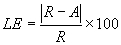
Analyze the linearity data for pollutant concentration monitors as follows. Calculate the percentage error in linearity based upon the reference value at the low-level, mid-level, and high-level concentrations specified in Section 6.2 of this Exhibit. Perform this calculation once during the certification test. Use the following equation to calculate the error in linearity for each reference value.
| (Equation A-4) |
| |
| where,
|
| |
| LE=Percentage Linearity error, based upon the reference value.
|
| |
| R=Reference value of Low-, mid-, or high-level calibration gas introduced into the monitoring system.
|
| |
| A=Average of the monitoring system responses.
|
| |
7.2 Calibration Error
7.2.1 Pollutant Concentration and Diluent Monitors
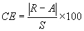
For each reference value, calculate the percentage calibration error based upon instrument span for daily calibration error tests using the following equation:
 (Equation A-5)
where,
CE = Calibration error as a percentage of the span of the instrument.
R = Reference value of zero or upscale (high-level or mid-level, as applicable) calibration gas introduced into the monitoring system.
A = Actual monitoring system response to the calibration gas.
S = Span of the instrument, as specified in Section 2 of this Exhibit.
7.2.2 Flow Monitor Calibration Error
For each reference value, calculate the percentage calibration error based upon span using the following equation:
 (Equation A-6)
where,
CE = Calibration error as a percentage of span.
R = Low or high level reference value specified in Section 2.2.2.1 of this Exhibit.
A = Actual flow monitor response to the reference value.
S = Flow monitor calibration span value as determined under Section 2.1.2.2 of this Exhibit.
7.3 Relative Accuracy for O2 Monitors, Mercury Monitoring Systems,
and Flow Monitors
Analyze the relative accuracy test audit data from the reference method tests for CO2 or O2 monitors used only for heat input rate determination, mercury monitoring systems used to determine mercury mass emissions under Sections 1.14 through 1.18 of Appendix B, and flow monitors using the following procedures. Summarize the results on a data sheet. An example is shown in Figure 2. Calculate the mean of the monitor or monitoring system measurement values. Calculate the mean of the reference method values. Using data from the automated data acquisition and handling system, calculate the arithmetic differences between the reference method and monitor measurement data sets. Then calculate the arithmetic mean of the difference, the standard deviation, the confidence coefficient, and the monitor or monitoring system relative accuracy using the following procedures and equations.
7.3.1 Arithmetic Mean
Calculate the arithmetic mean of the differences, d, of a data set as follows.
 (Equation A-7)
where,
n = Number of data points.
di = The difference between a reference method value and the corresponding continuous emission monitoring system value (RMi–CEMi) at a given point in time i.
7.3.2 Standard Deviation
Calculate the standard deviation, Sd, of a data set as follows:
 (Equation A-8)
where,
n = Number of data points.
di = The difference between a reference method value and the corresponding continuous emission monitoring system value (RMi–CEMi) at a given point in time i.
7.3.3 Confidence Coefficient
Calculate the confidence coefficient (one-tailed), cc, of a data set as follows:
 (Equation A-9)
where,
t0.025=t value (see Table 7-1).
Table 7-1 t-Values
----------------------------------------------
n-1 t0.025 n-1 t0.025 n-1 t0. 025
----------------------------------------------
1 ...... 12.706 12 2.179 23 2.069
2 ....... 4.303 13 2.160 24 2.064
3 ....... 3.182 14 2.145 25 2.060
4 ....... 2.776 15 2.131 26 2.056
5 ....... 2.571 16 2.120 27 2.052
6 ....... 2.447 17 2.110 28 2.048
7 ....... 2.365 18 2.101 29 2.045
8 ....... 2.306 19 2.093 30 2.042
9 ....... 2.262 20 2.086 40 2.021
10 ...... 2.228 21 2.080 60 2.000
11 ...... 2.201 22 2.074 >60 1.960
----------------------------------------------
7.3.4 Relative Accuracy
Calculate the relative accuracy of a data set using the following equation.
 (Equation A-10)
where,
 = Arithmetic mean of the reference method values.
 = The absolute value of the mean difference between the reference method values and the corresponding continuous emission monitoring system values.
 = The absolute value of the confidence coefficient.
7.4 Bias Test
Test the following relative accuracy test audit data sets for bias: flow monitors; mercury concentration monitoring systems, and sorbent trap monitoring systems, using the procedures outlined in Sections 7.4.1 through 7.4.4 of this Exhibit. For multiple-load flow RATAs, perform a bias test at each load level designated as normal under Section 6.5.2.1 of this Exhibit.
7.4.1 Arithmetic Mean
Calculate the arithmetic mean of the difference, "d", of the data set using Equation A-7 of this Exhibit. To calculate bias for a flow monitor, "d" is, for each paired data point, the difference between the flow rate values (in scfh) obtained from the reference method and the monitor. To calculate bias for a mercury monitoring system when using the Ontario Hydro Method or Method 29 in appendix A-8 to 40 CFR 60, incorporated by reference in Section 225.140, "d" is, for each data point, the difference between the average mercury concentration value (in µg/m3) from the paired Ontario Hydro or Method 29 in appendix A-8 to 40 CFR 60 sampling trains and the concentration measured by the monitoring system. For sorbent trap monitoring systems, use the average mercury concentration measured by the paired traps in the calculation of "d".
7.4.2 Standard Deviation
Calculate the standard deviation, Sd, of the data set using Equation A-8.
7.4.3 Confidence Coefficient
Calculate the confidence coefficient, cc, of the data set using Equation A-9.
7.4.4 Bias Test
If, for the relative accuracy test audit data set being tested, the mean difference, d, is less than or equal to the absolute value of the confidence coefficient,  , the monitor or monitoring system has passed the bias test. If the mean difference, d, is greater than the absolute value of the confidence coefficient,
  , the monitor or monitoring system has failed to meet the bias test requirement.
7.5 Reference Flow-to-Load Ratio or Gross Heat Rate
| (a)
| Except as provided in Section 7.6 of this Exhibit, the owner or operator must determine  , the reference value of the ratio of flow rate to unit load, each time that a passing flow RATA is performed at a load level designated as normal in Section 6.5.2.1 of this Exhibit. The owner or operator must report the current value of , the reference value of the ratio of flow rate to unit load, each time that a passing flow RATA is performed at a load level designated as normal in Section 6.5.2.1 of this Exhibit. The owner or operator must report the current value of  in the electronic quarterly report required under 40 CFR 75.64
, incorporated by reference in Section 225.140, and must also report the completion date of the associated RATA. If two load levels have been designated as normal under Section 6.5.2.1 of this Exhibit, the owner or operator must determine a separate in the electronic quarterly report required under 40 CFR 75.64
, incorporated by reference in Section 225.140, and must also report the completion date of the associated RATA. If two load levels have been designated as normal under Section 6.5.2.1 of this Exhibit, the owner or operator must determine a separate  value for each of the normal load levels. The reference flow-to-load ratio must be calculated as follows: value for each of the normal load levels. The reference flow-to-load ratio must be calculated as follows: |
| |
 (Equation A-13)
where,
 = Reference value of the flow-to-load ratio, from the most recent normal-load flow RATA, scfh/megawatts, scfh/1000 lb/hr of steam, or scfh/ (mmBtu/hr of steam output).
 = Average stack gas volumetric flow rate measured by the reference method during the normal-load RATA, scfh.
 = Average unit load during the normal-load flow RATA, megawatts, 1000 lb/hr of steam, or mmBtu/hr of thermal output.
| (b)
| In Equation A-13, for a common stack, determine  by summing, for each RATA run, the operating loads of all units discharging through the common stack, and then taking the arithmetic average of the summed loads. For a unit that discharges its emissions through multiple stacks, either determine a single value of by summing, for each RATA run, the operating loads of all units discharging through the common stack, and then taking the arithmetic average of the summed loads. For a unit that discharges its emissions through multiple stacks, either determine a single value of  for the unit or a separate value of for the unit or a separate value of  for each stack. In the former case, calculate for each stack. In the former case, calculate  by summing, for each RATA run, the volumetric flow rates through the individual stacks and then taking the arithmetic average of the summed RATA run flow rates. In the latter case, calculate the value of by summing, for each RATA run, the volumetric flow rates through the individual stacks and then taking the arithmetic average of the summed RATA run flow rates. In the latter case, calculate the value of  for each stack by taking the arithmetic average, for all RATA runs, of the flow rates through the stack. For a unit with a multiple stack discharge configuration consisting of a main stack and a bypass stack (e.g., a unit with a wet SO2 scrubber), determine for each stack by taking the arithmetic average, for all RATA runs, of the flow rates through the stack. For a unit with a multiple stack discharge configuration consisting of a main stack and a bypass stack (e.g., a unit with a wet SO2 scrubber), determine  separately for each stack at the time of the normal load flow RATA. Round off the value of separately for each stack at the time of the normal load flow RATA. Round off the value of  to two decimal places. to two decimal places. |
| |
| (c)
| In addition to determining  or as an alternative to determine or as an alternative to determine  , a reference value of the gross heat rate (GHR) may be determined. In order to use this option, quality assured diluent gas (CO2 or O2) must be available for each hour of the most recent normal-load flow RATA. The reference value of the GHR must be determined as follows: , a reference value of the gross heat rate (GHR) may be determined. In order to use this option, quality assured diluent gas (CO2 or O2) must be available for each hour of the most recent normal-load flow RATA. The reference value of the GHR must be determined as follows: |
| |
 (Equation A-13a)
where,
 = Reference value of the gross heat rate at the time of the most recent normal-load flow RATA, Btu/kwh, Btu/lb steam load, or Btu heat input/mmBtu steam output.
 = Average hourly heat input during the normal-load flow RATA, as determined using the applicable equation in Exhibit C to this Appendix, mmBtu/hr. For multiple stack configurations, if the reference GHR value is determined separately for each stack, use the hourly heat input measured at each stack. If the reference GHR is determined at the unit level, sum the hourly heat inputs measured at the individual stacks.
 = Average unit load during the normal-load flow RATA, megawatts, 1000 lb/hr of steam, or mmBtu/hr thermal output.
| (d)
| In the calculation of  , use , use  , the average volumetric flow rate measured by the reference method during the RATA, and use the average diluent gas concentration measured during the flow RATA (i.e., the arithmetic average of the diluent gas concentrations for all clock hours in which a RATA run was performed). , the average volumetric flow rate measured by the reference method during the RATA, and use the average diluent gas concentration measured during the flow RATA (i.e., the arithmetic average of the diluent gas concentrations for all clock hours in which a RATA run was performed). |
| |
7.6 Flow-to-Load Test Exemptions
| (a)
| For complex stack configurations (e.g., when the effluent from a unit is divided and discharges through multiple stacks in such a manner that the flow rate in the individual stacks cannot be correlated with unit load), the owner or operator may petition the USEPA under 40 CFR 75.66
, incorporated by reference in Section 225.140, for an exemption from the requirements of Section 7.7 to Appendix A to 40 CFR Part 75 and Section 2.2.5 of Exhibit B to Appendix B. The petition must include sufficient information and data to demonstrate that a flow-to-load or gross heat rate evaluation is infeasible for the complex stack configuration. |
| |
| (b)
| Units that do not produce electrical output (in megawatts) or thermal output (in klb of steam per hour) are exempted from the flow-to-load ratio test requirements of Section 7.5 of this Exhibit and Section 2.2.5 of Exhibit B to Appendix B. |
| |
Figures for Exhibit A to Appendix B
Figure 1.--Linearity Error Determination
-------------------------------------------------------------------------------
Day Date and Reference Monitor Difference Percent of
time value value reference
value
-------------------------------------------------------------------------------
Low-level:
-------------------------------------------------------------------------------
-------------------------------------------------------------------------------
-------------------------------------------------------------------------------
-------------------------------------------------------------------------------
-------------------------------------------------------------------------------
-------------------------------------------------------------------------------
-------------------------------------------------------------------------------
Mid-level:
-------------------------------------------------------------------------------
-------------------------------------------------------------------------------
-------------------------------------------------------------------------------
-------------------------------------------------------------------------------
-------------------------------------------------------------------------------
-------------------------------------------------------------------------------
-------------------------------------------------------------------------------
High-level:
-------------------------------------------------------------------------------
-------------------------------------------------------------------------------
-------------------------------------------------------------------------------
-------------------------------------------------------------------------------
-------------------------------------------------------------------------------
-------------------------------------------------------------------------------
Figure 2.--Relative Accuracy Determination (Pollutant Concentration Monitors)
-------------------------------------------------------------------------------
SO2 (ppm [FNc]) CO2 (Pollutant) (ppm [FNc])
----------------------------- -------------------------------
Date Date
Run and RM [FNa] M [FNb] Diff and RM [FNa] M [FNb] Diff
No. time time
-------------------------------------------------------------------------------
1
-------------------------------------------------------------------------------
2
-------------------------------------------------------------------------------
3
-------------------------------------------------------------------------------
4
-------------------------------------------------------------------------------
5
-------------------------------------------------------------------------------
6
-------------------------------------------------------------------------------
7
-------------------------------------------------------------------------------
8
-------------------------------------------------------------------------------
9
-------------------------------------------------------------------------------
10
-------------------------------------------------------------------------------
11
-------------------------------------------------------------------------------
12
-------------------------------------------------------------------------------
Arithmetic Mean Difference (Eq. A-7).
Confidence Coefficient (Eq. A-9). Relative
Accuracy (Eq. A-10).
-------------------------------------------------------------------------------
[FNa] RM means "reference method data."
[FNb] M means "monitor data."
[FNc] Make sure the RM and M data are on a consistent basis, either wet or dry.
Figure 3.--Relative Accuracy Determination (Flow Monitors)
-------------------------------------------------------------------------------
Flow rate (Low) Flow rate (Normal) Flow rate (High)
(scf/hr) [FNa] (scf/hr) [FNa] (scf/hr) [FNa]
------------------- ------------------ --------------------
Date Date Date
Run and and and
No. time RM M Diff time RM M Diff time RM M Diff
-------------------------------------------------------------------------------
1
-------------------------------------------------------------------------------
2
-------------------------------------------------------------------------------
3
-------------------------------------------------------------------------------
4
-------------------------------------------------------------------------------
5
-------------------------------------------------------------------------------
6
-------------------------------------------------------------------------------
7
-------------------------------------------------------------------------------
8
-------------------------------------------------------------------------------
9
-------------------------------------------------------------------------------
10
-------------------------------------------------------------------------------
11
-------------------------------------------------------------------------------
12
-------------------------------------------------------------------------------
Arithmetic Mean Difference (Eq.
A-7). Confidence Coefficient
(Eq. A-9). Relative Accuracy
(Eq. A-10).
-------------------------------------------------------------------------------
[FNa] Make sure the RM and M data are on a consistent basis, either wet or dry.
Figure 4.--Relative Accuracy Determination (NOX/Diluent Combined System)
-------------------------------------------------------------------------------
Reference method data NOX system (lb/mmBtu)
--------------------------- -----------------------
Run No. Date and time NOX( ) [FNa] O2/CO2% RM M Difference
-------------------------------------------------------------------------------
1
-------------------------------------------------------------------------------
2
-------------------------------------------------------------------------------
3
-------------------------------------------------------------------------------
4
-------------------------------------------------------------------------------
5
-------------------------------------------------------------------------------
6
-------------------------------------------------------------------------------
7
-------------------------------------------------------------------------------
8
-------------------------------------------------------------------------------
9
-------------------------------------------------------------------------------
10
-------------------------------------------------------------------------------
11
-------------------------------------------------------------------------------
12
-------------------------------------------------------------------------------
Arithmetic Mean Difference (Eq. A-7). Confidence
Coefficient (Eq. A-9). Relative Accuracy (Eq. A-10).
-------------------------------------------------------------------------------
[FNa] Specify units: ppm, lb/dscf, mg/dscm.
Figure 5--Cycle Time
| Date of test __________________________________________________________________
|
| |
| Component/system ID#: ________________________________________________________
|
| |
| Analyzer type _________________________________________________________________
|
| |
| Serial Number _________________________________________________________________
|
| |
| High level gas concentration: ______ ppm/% (circle one)
|
| |
| Zero level gas concentration: ______ ppm/% (circle one)
|
| |
| Analyzer span setting: ______ ppm/% (circle one)
|
| |
| Upscale:
|
| |
| Stable starting monitor value: ______ ppm/% (circle one)
|
| |
| Stable ending monitor reading: ______ ppm/% (circle one)
|
| |
| Elapsed time: ______ seconds
|
| |
| Downscale:
|
| |
| Stable starting monitor value: ______ ppm/% (circle one)
|
| |
| Stable ending monitor value: ______ ppm/% (circle one)
|
| |
| Elapsed time: ______ seconds
|
| |
| Component cycle time= ______ seconds
|
| |
| System cycle time= ______ seconds
|
| |
A. To determine the upscale cycle time (Figure 6a), measure the flue gas emissions until the response stabilizes. Record the stabilized value (see Section 6.4 of this Exhibit for the stability criteria).
B. Inject a high-level calibration gas into the port leading to the calibration cell or thimble (Point B). Allow the analyzer to stabilize. Record the stabilized value.
C. Determine the step change. The step change is equal to the difference between the final stable calibration gas value (Point D) and the stabilized stack emissions value (Point A).
D. Take 95% of the step change value and add the result to the stabilized stack emissions value (Point A). Determine the time at which 95% of the step change occurred (Point C).
E. Calculate the upscale cycle time by subtracting the time at which the calibration gas was injected (Point B) from the time at which 95% of the step change occurred (Point C). In this example, upscale cycle time = (11-5) = 6 minutes.
F. To determine the downscale cycle time (Figure 6b) repeat the procedures above, except that a zero gas is injected when the flue gas emissions have stabilized, and 95% of the step change in concentration is subtracted from the stabilized stack emissions value.
G. Compare the upscale and downscale cycle time values. The longer of these two times is the cycle time for the analyzer.
Exhibit B to Appendix B--Quality Assurance and Quality Control Procedures
1. Quality Assurance/Quality Control Program
Develop and implement a quality assurance/quality control (QA/QC) program for the continuous emission monitoring systems, and their components. At a minimum, include in each QA/QC program a written plan that describes in detail (or that refers to separate documents containing) complete, step-by-step procedures and operations for each of the following activities. Upon request from regulatory authorities, the source must make all procedures, maintenance records, and ancillary supporting documentation from the manufacturer (e.g., software coefficients and troubleshooting diagrams) available for review during an audit. Electronic storage of the information in the QA/QC plan is permissible, provided that the information can be made available in hardcopy upon request during an audit.
1.1 Requirements for All Monitoring Systems
1.1.1 Preventive Maintenance
Keep a written record of procedures needed to maintain the monitoring system in proper operating condition and a schedule for those procedures. This must, at a minimum, include procedures specified by the manufacturers of the equipment and, if applicable, additional or alternate procedures developed for the equipment.
1.1.2 Recordkeeping and Reporting
Keep a written record describing procedures that will be used to implement the recordkeeping and reporting requirements in subparts E and G of 40 CFR 75, incorporated by reference in Section 225.140, and Sections 1.10 through 1.13 of Appendix B, as applicable.
1.1.3 Maintenance Records
Keep a record of all testing, maintenance, or repair activities performed on any monitoring system or component in a location and format suitable for inspection. A maintenance log may be used for this purpose. The following records should be maintained: date, time, and description of any testing, adjustment, repair, replacement, or preventive maintenance action performed on any monitoring system and records of any corrective actions associated with a monitor's outage period. Additionally, any adjustment that recharacterizes a system's ability to record and report emissions data must be recorded (e.g., changing of flow monitor or moisture monitoring system polynomial coefficients, K factors or mathematical algorithms, changing of temperature and pressure coefficients and dilution ratio settings), and a written explanation of the procedures used to make the adjustment(s) must be kept.
The requirements in Section 6.1.2 of Exhibit A to this Appendix must be met by any Air Emissions Testing Body (AETB) performing the semiannual/annual RATAs described in Section 2.3 of this Exhibit and the mercury emission tests described in Sections 1.15(c) and 1.15(d)(4) of Appendix B.
1.2 Specific Requirements for Continuous Emissions Monitoring Systems
1.2.1 Calibration Error Test and Linearity Check Procedures
Keep a written record of the procedures used for daily calibration error tests and linearity checks (e.g., how gases are to be injected, adjustments of flow rates and pressure, introduction of reference values, length of time for injection of calibration gases, steps for obtaining calibration error or error in linearity, determination of interferences, and when calibration adjustments should be made). Identify any calibration error test and linearity check procedures specific to the continuous emission monitoring system that vary from the procedures in Exhibit A to this Appendix.
1.2.2 Calibration and Linearity Adjustments
Explain how each component of the continuous emission monitoring system will be adjusted to provide correct responses to calibration gases, reference values, and/or indications of interference both initially and after repairs or corrective action. Identify equations, conversion factors and other factors affecting calibration of each continuous emission monitoring system.
1.2.3 Relative Accuracy Test Audit Procedures
Keep a written record of procedures and details peculiar to the installed continuous emission monitoring systems that are to be used for relative accuracy test audits, such as sampling and analysis methods.
1.2.4 Parametric Monitoring for Units With Add-on Emission Controls
The owner or operator shall keep a written (or electronic) record including a list of operating parameters for the add-on mercury emission controls, as applicable, and the range of each operating parameter that indicates the add-on emission controls are operating properly. The owner or operator shall keep a written (or electronic) record of the parametric monitoring data during each mercury missing data period.
1.3 Requirements for Sorbent Trap Monitoring Systems
1.3.1 Sorbent Trap Identification and Tracking
Include procedures for inscribing or otherwise permanently marking a unique identification number on each sorbent trap, for tracking purposes. Keep records of the ID of the monitoring system in which each sorbent trap is used, and the dates and hours of each mercury collection period.
1.3.2 Monitoring System Integrity and Data Quality
Explain the procedures used to perform the leak checks when sorbent traps are placed in service and removed from service. Also explain the other QA procedures used to ensure system integrity and data quality, including, but not limited to, gas flow meter calibrations, verification of moisture removal, and ensuring air-tight pump operation. In addition, the QA plan must include the data acceptance and quality control criteria in Section 8
of Exhibit D to this Appendix. All reference meters used to calibrate the gas flow meters (e.g., wet test meters) must be periodically recalibrated. Annual, or more frequent, recalibration is recommended. If a NIST-traceable calibration device is used as a reference flow meter, the QA plan must include a protocol for ongoing maintenance and periodic recalibration to maintain the accuracy and NIST-traceability of the calibrator.
1.3.3 Mercury Analysis
Explain the chain of custody employed in packing, transporting, and analyzing the sorbent traps (see Sections 7.2.8 and 7.2.9 in Exhibit D to this Appendix.). Keep records of all mercury analyses. The analyses must be performed in accordance with the procedures described in Section 10
of Exhibit D to this Appendix.
1.3.4 Laboratory Certification
The QA Plan must include documentation that the laboratory performing the analyses on the carbon sorbent traps is certified by the International Organization for Standardization (ISO) to have a proficiency that meets the requirements of ISO 17025. Alternatively, if the laboratory performs the spike recovery study described in Section 10.3 of Exhibit D to this Appendix
and repeats that procedure annually, ISO certification is not required.
1.3.5 Data Collection Period
State, and provide the rationale for, the minimum acceptable data collection period (e.g., one day, one week, etc.) for the size of sorbent trap selected for the monitoring. Include in the discussion such factors as the mercury concentration in the stack gas, the capacity of the sorbent trap, and the minimum mass of mercury required for the analysis.
1.3.6 Relative Accuracy Test Audit Procedures
Keep records of the procedures and details peculiar to the sorbent trap monitoring systems that are to be followed for relative accuracy test audits, such as sampling and analysis methods.
2. Frequency of Testing
A summary chart showing each quality assurance test and the frequency at which each test is required is located at the end of this Exhibit in Figure 1.
2.1 Daily Assessments
Perform the following daily assessments to quality-assure the hourly data recorded by the monitoring systems during each period of unit operation, or, for a bypass stack or duct, each period in which emissions pass through the bypass stack or duct. These requirements are effective as of the date when the monitor or continuous emission monitoring system completes certification testing.
2.1.1 Calibration Error Test
Except as provided in Section 2.1.1.2 of this Exhibit, perform the daily calibration error test of each gas monitoring system (including moisture monitoring systems consisting of wet- and dry-basis O2 analyzers) according to the procedures in Section 6.3.1 of Exhibit A to this Appendix, and perform the daily calibration error test of each flow monitoring system according to the procedure in Section 6.3.2 of Exhibit A to this Appendix. When two measurement ranges (low and high) are required for a particular parameter, perform sufficient calibration error tests on each range to validate the data recorded on that range, according to the criteria in Section 2.1.5 of this Exhibit.
For units with add-on emission controls and dual-span or auto-ranging monitors, and other units that use the maximum expected concentration to determine calibration gas values, perform the daily calibration error tests on each scale that has been used since the previous calibration error test. For example, if the pollutant concentration has not exceeded the low-scale value (based on the maximum expected concentration) since the previous calibration error test, the calibration error test may be performed on the low-scale only. If, however, the concentration has exceeded the low-scale span value for one hour or longer since the previous calibration error test, perform the calibration error test on both the low- and high-scales.
2.1.1.1 On-line Daily Calibration Error Tests.
Except as provided in Section 2.1.1.2 of this Exhibit, all daily calibration error tests must be performed while the unit is in operation at normal, stable conditions (i.e. "on-line").
2.1.1.2 Off-line Daily Calibration Error Tests.
Daily calibrations may be performed while the unit is not operating (i.e., "off-line") and may be used to validate data for a monitoring system that meets the following conditions:
| (1)
| An initial demonstration test of the monitoring system is successfully completed and the results are reported in the quarterly report required under 40 CFR 75.64
, incorporated by reference in Section 225.140. The initial demonstration test, hereafter called the "off-line calibration demonstration", consists of an off-line calibration error test followed by an on-line calibration error test. Both the off-line and on-line portions of the off-line calibration demonstration must meet the calibration error performance specification in Section 3.1 of Exhibit A to Appendix B.
Upon completion of the off-line portion of the demonstration, the zero and upscale monitor responses may be adjusted, but only toward the true values of the calibration gases or reference signals used to perform the test and only in accordance with the routine calibration adjustment procedures specified in the quality control program required under Section 1
of this Exhibit. Once these adjustments are made, no further adjustments may be made to the monitoring system until after completion of the on-line portion of the off-line calibration demonstration. Within 26 clock hours of the completion hour of the off-line portion of the demonstration, the monitoring system must successfully complete the first attempted calibration error test, i.e., the on-line portion of the demonstration. |
| |
| (2)
| For each monitoring system that has passed the off-line calibration demonstration, off-line calibration error tests may be used on a limited basis to validate data, in accordance with paragraph (2) in Section 2.1.5.1 of this Exhibit. |
| |
2.1.2 Daily Flow Interference Check
Perform the daily flow monitor interference checks specified in Section 2.2.2.2 of Exhibit A to this Appendix while the unit is in operation at normal, stable conditions.
2.1.3 Additional Calibration Error Tests and Calibration Adjustments
| (a)
| In addition to the daily calibration error tests required under Section 2.1.1 of this Exhibit, a calibration error test of a monitor must be performed in accordance with Section 2.1.1 of this Exhibit, as follows: whenever a daily calibration error test is failed; whenever a monitoring system is returned to service following repair or corrective maintenance that could affect the monitor's ability to accurately measure and record emissions data; or after making certain calibration adjustments, as described in this Section. Except in the case of the routine calibration adjustments described in this Section, data from the monitor are considered invalid until the required additional calibration error test has been successfully completed. |
| |
| (b)
| Routine calibration adjustments of a monitor are permitted after any successful calibration error test. These routine adjustments must be made so as to bring the monitor readings as close as practicable to the known tag values of the calibration gases or to the actual value of the flow monitor reference signals. An additional calibration error test is required following routine calibration adjustments where the monitor's calibration has been physically adjusted (e.g., by turning a potentiometer) to verify that the adjustments have been made properly. An additional calibration error test is not required, however, if the routine calibration adjustments are made by means of a mathematical algorithm programmed into the data acquisition and handling system. It is recommended that routine calibration adjustments be made, at a minimum, whenever the daily calibration error exceeds the limits of the applicable performance specification in Exhibit A to this Appendix for the pollutant concentration monitor, CO2 or O2 monitor, or flow monitor. |
| |
| (c)
| Additional (non-routine) calibration adjustments of a monitor are permitted prior to (but not during) linearity checks and RATAs and at other times, provided that an appropriate technical justification is included in the quality control program required under Section 1
of this Exhibit. The allowable non-routine adjustments are as follows. The owner or operator may physically adjust the calibration of a monitor (e.g., by means of a potentiometer), provided that the post-adjustment zero and upscale responses of the monitor are within the performance specifications of the instrument given in Section 3.1 of Exhibit A to this Appendix
. An additional calibration error test is required following such adjustments to verify that the monitor is operating within the performance specifications at both the zero and upscale calibration levels. |
| |
2.1.4 Data Validation
| (a)
| An out-of-control period occurs when the calibration error of a CO2 or O2 monitor (including O2 monitors used to measure CO2 emissions or percent moisture) exceeds 1.0 percent CO2 or O2, or when the calibration error of a flow monitor or a moisture sensor exceeds 6.0 percent of the span value, which is twice the applicable specification of Exhibit A to this Appendix. Notwithstanding, a differential pressure-type flow monitor for which the calibration error exceeds 6.0 percent of the span value will not be considered out-of-control if  , the absolute value of the difference between the monitor response and the reference value in Equation A-6 of Exhibit A to this Appendix, is < 0.02 inches of water. For a mercury monitor, an out-of-control period occurs when the calibration error exceeds 5.0% of the span value. Notwithstanding, the mercury monitor will not be considered out-of-control if , the absolute value of the difference between the monitor response and the reference value in Equation A-6 of Exhibit A to this Appendix, is < 0.02 inches of water. For a mercury monitor, an out-of-control period occurs when the calibration error exceeds 5.0% of the span value. Notwithstanding, the mercury monitor will not be considered out-of-control if  in Equation A-6 does not exceed 1.0 µg/scm. The out-of-control period begins upon failure of the calibration error test and ends upon completion of a successful calibration error test. Note, that if a failed calibration, corrective action, and successful calibration error test occur within the same hour, emission data for that hour recorded by the monitor after the successful calibration error test may be used for reporting purposes, provided that two or more valid readings are obtained as required by Section 1.2 of this Appendix. Emission data must not be reported from an out-of-control monitor. in Equation A-6 does not exceed 1.0 µg/scm. The out-of-control period begins upon failure of the calibration error test and ends upon completion of a successful calibration error test. Note, that if a failed calibration, corrective action, and successful calibration error test occur within the same hour, emission data for that hour recorded by the monitor after the successful calibration error test may be used for reporting purposes, provided that two or more valid readings are obtained as required by Section 1.2 of this Appendix. Emission data must not be reported from an out-of-control monitor. |
| |
| (b)
| An out-of-control period also occurs whenever interference of a flow monitor is identified. The out-of-control period begins with the hour of completion of the failed interference check and ends with the hour of completion of an interference check that is passed. |
| |
2.1.5 Quality Assurance of Data With Respect to Daily Assessments
When a monitoring system passes a daily assessment (i.e., daily calibration error test or daily flow interference check), data from that monitoring system are prospectively validated for 26 clock hours (i.e., 24 hours plus a 2-hour grace period) beginning with the hour in which the test is passed, unless another assessment (i.e. a daily calibration error test, an interference check of a flow monitor, a quarterly linearity check, a quarterly leak check, or a relative accuracy test audit) is failed within the 26-hour period.
2.1.5.1 Data Invalidation with Respect to Daily Assessments.
The following specific rules apply to the invalidation of data with respect to daily assessments:
| (1)
| Data from a monitoring system are invalid, beginning with the first hour following the expiration of a 26-hour data validation period or beginning with the first hour following the expiration of an 8-hour start-up grace period (as provided under Section 2.1.5.2 of this Exhibit), if the required subsequent daily assessment has not been conducted. |
| |
| (2)
| For a monitor that has passed the off-line calibration demonstration, a combination of on-line and off-line calibration error tests may be used to validate data from the monitor, as follows. For a particular unit (or stack) operating hour, data from a monitor may be validated using a successful off-line calibration error test if: (a) An on-line calibration error test has been passed within the previous 26 unit (or stack) operating hours; and (b) the 26 clock hour data validation window for the off-line calibration error test has not expired. If either of these conditions is not met, then the data from the monitor are invalid with respect to the daily calibration error test requirement. Data from the monitor must remain invalid until the appropriate on-line or off-line calibration error test is successfully completed so that both conditions (a) and (b) are met. |
| |
| (3)
| For units with two measurement ranges (low and high) for a particular parameter, when separate analyzers are used for the low and high ranges, a failed or expired calibration on one of the ranges does not affect the quality-assured data status on the other range. For a dual-range analyzer (i.e., a single analyzer with two measurement scales), a failed calibration error test on either the low or high scale results in an out-of-control period for the monitor. Data from the monitor remain invalid until corrective actions are taken and "hands-off" calibration error tests have been passed on both ranges. However, if the most recent calibration error test on the high scale was passed but has expired, while the low scale is up-to-date on its calibration error test requirements (or vice-versa), the expired calibration error test does not affect the quality-assured status of the data recorded on the other scale. |
| |
2.1.5.2 Daily Assessment Start-Up Grace Period.
For the purpose of quality assuring data with respect to a daily assessment (i.e. a daily calibration error test or a flow interference check), a start-up grace period may apply when a unit begins to operate after a period of non-operation. The start-up grace period for a daily calibration error test is independent of the start-up grace period for a daily flow interference check. To qualify for a start-up grace period for a daily assessment, there are two requirements:
| (1)
| The unit must have resumed operation after being in outage for 1 or more hours (i.e., the unit must be in a start-up condition) as evidenced by a change in unit operating time from zero in one clock hour to an operating time greater than zero in the next clock hour. |
| |
| (2)
| For the monitoring system to be used to validate data during the grace period, the previous daily assessment of the same kind must have been passed on-line within 26 clock hours prior to the last hour in which the unit operated before the outage. In addition, the monitoring system must be in-control with respect to quarterly and semi-annual or annual assessments. |
| |
If both of the above conditions are met, then a start-up grace period of up to 8 clock hours applies, beginning with the first hour of unit operation following the outage. During the start-up grace period, data generated by the monitoring system are considered quality-assured. For each monitoring system, a start-up grace period for a calibration error test or flow interference check ends when either: (1) a daily assessment of the same kind (i.e., calibration error test or flow interference check) is performed; or (2) 8 clock hours have elapsed (starting with the first hour of unit operation following the outage), whichever occurs first.
2.1.6 Data Recording
Record and tabulate all calibration error test data according to month, day, clock-hour, and magnitude in either ppm, percent volume, or scfh. Program monitors that automatically adjust data to the corrected calibration values (e.g., microprocessor control) to record either: (1) The unadjusted concentration or flow rate measured in the calibration error test prior to resetting the calibration, or (2) the magnitude of any adjustment. Record the following applicable flow monitor interference check data: (1) Sample line/sensing port pluggage, and (2) malfunction of each RTD, transceiver, or equivalent.
2.2 Quarterly Assessments
For each primary and redundant backup monitor or monitoring system, perform the following quarterly assessments. This requirement is applies as of the calendar quarter following the calendar quarter in which the monitor or continuous emission monitoring system is provisionally certified.
2.2.1 Linearity Check
Unless a particular monitor (or monitoring range) is exempted under this paragraph or under Section 6.2 of Exhibit A to this Appendix, perform a linearity check, in accordance with the procedures in Section 6.2 of Exhibit A to this Appendix, for each primary and redundant backup, mercury, pollutant concentration monitor and each primary and redundant backup CO2 or O2 monitor (including O2 monitors used to measure CO2 emissions or to continuously monitor moisture) at least once during each QA operating quarter, as defined in 40 CFR 72.2
, incorporated by reference in Section 225.140. For mercury monitors, perform the linearity checks using elemental mercury standards. Alternatively, you may perform 3-level system integrity checks at the same three calibration gas levels (i.e., low, mid, and high), using a NIST-traceable source of oxidized mercury. If you choose this option, the performance specification in Section 3.2(c)
of Exhibit A to this part must be met at each gas level. For units using both a low and high span value, a linearity check is required only on the range(s) used to record and report emission data during the QA operating quarter. Conduct the linearity checks no less than 30 days apart, to the extent practicable. The data validation procedures in Section 2.2.3(e) of this Exhibit must be followed.
2.2.2 Leak Check
For differential pressure flow monitors, perform a leak check of all sample lines (a manual check is acceptable) at least once during each QA operating quarter. For this test, the unit does not have to be in operation. Conduct the leak checks no less than 30 days apart, to the extent practicable. If a leak check is failed, follow the applicable data validation procedures in Section 2.2.3(g) of this Exhibit.
2.2.3 Data Validation
| (a)
| A linearity check must not be commenced if the monitoring system is operating out-of-control with respect to any of the daily or semiannual quality assurance assessments required by Sections 2.1 and 2.3 of this Exhibit or with respect to the additional calibration error test requirements in Section 2.1.3 of this Exhibit. |
| |
| (b)
| Each required linearity check must be done according to paragraph (b)(1), (b)(2) or (b)(3) of this Section: |
| |
| (1)
| The linearity check may be done "cold," i.e., with no corrective maintenance, repair, calibration adjustments, re-linearization or reprogramming of the monitor prior to the test. |
| |
| (2)
| The linearity check may be done after performing only the routine or non-routine calibration adjustments described in Section 2.1.3 of this Exhibit at the various calibration gas levels (zero, low, mid or high), but no other corrective maintenance, repair, re-linearization or reprogramming of the monitor. Trial gas injection runs may be performed after the calibration adjustments and additional adjustments within the allowable limits in Section 2.1.3 of this Exhibit may be made prior to the linearity check, as necessary, to optimize the performance of the monitor. The trial gas injections need not be reported, provided that they meet the specification for trial gas injections in Section
1.4(b)(3)(G)(v) of this Appendix. However, if, for any trial injection, the specification in Section
1.4(b)(3)(G)(v) is not met, the trial injection must be counted as an aborted linearity check. |
| |
| (3)
| The linearity check may be done after repair, corrective maintenance or reprogramming of the monitor. In this case, the monitor must be considered out-of-control from the hour in which the repair, corrective maintenance or reprogramming is commenced until the linearity check has been passed. Alternatively, the data validation procedures and associated timelines in Sections
1.4(b)(3)(B) through (I)
of this Appendix may be followed upon completion of the necessary repair, corrective maintenance, or reprogramming. If the procedures in Section
1.4(b)(3) are used, the words "quality assurance" apply instead of the word "recertification". |
| |
| (c)
| Once a linearity check has been commenced, the test must be done hands-off. That is, no adjustments of the monitor are permitted during the linearity test period, other than the routine calibration adjustments following daily calibration error tests, as described in Section 2.1.3 of this Exhibit. If a routine daily calibration error test is performed and passed just prior to a linearity test (or during a linearity test period) and a mathematical correction factor is automatically applied by the DAHS, the correction factor must be applied to all subsequent data recorded by the monitor, including the linearity test data. |
| |
| (d)
| If a daily calibration error test is failed during a linearity test period, prior to completing the test, the linearity test must be repeated. Data from the monitor are invalidated prospectively from the hour of the failed calibration error test until the hour of completion of a subsequent successful calibration error test. The linearity test must not be commenced until the monitor has successfully completed a calibration error test. |
| |
| (e)
| An out-of-control period occurs when a linearity test is failed (i.e., when the error in linearity at any of the three concentrations in the quarterly linearity check (or any of the six concentrations, when both ranges of a single analyzer with a dual range are tested) exceeds the applicable specification in Section 3.2 of Exhibit A to this Appendix) or when a linearity test is aborted due to a problem with the monitor or monitoring system. The out-of-control period begins with the hour of the failed or aborted linearity check and ends with the hour of completion of a satisfactory linearity check following corrective action and/or monitor repair, unless the option in paragraph (b)(3) of this Section to use the data validation procedures and associated timelines in Section
1.4(b)(3)(B) through (I)
of this Appendix has been selected, in which case the beginning and end of the out-of-control period must be determined in accordance with Sections
1.4(b)(3)(G)(i) and (ii). For a dual-range analyzer, "hands-off" linearity checks must be passed on both measurement scales to end the out-of-control period. |
| |
| (f)
| No more than four successive calendar quarters must elapse after the quarter in which a linearity check of a monitor or monitoring system (or range of a monitor or monitoring system) was last performed without a subsequent linearity test having been conducted. If a linearity test has not been completed by the end of the fourth calendar quarter since the last linearity test, then the linearity test must be completed within a 168 unit operating hour or stack operating hour "grace period" (as provided in Section 2.2.4 of this Exhibit) following the end of the fourth successive elapsed calendar quarter, or data from the CEMS (or range) will become invalid. |
| |
| (g)
| An out-of-control period also occurs when a flow monitor sample line leak is detected. The out-of-control period begins with the hour of the failed leak check and ends with the hour of a satisfactory leak check following corrective action. |
| |
| (h)
| For each monitoring system, report the results of all completed and partial linearity tests that affect data validation (i.e., all completed, passed linearity checks; all completed, failed linearity checks; and all linearity checks aborted due to a problem with the monitor, including trial gas injections counted as failed test attempts under paragraph (b)(2) of this Section or under Section 1.4(b)(3)(G)(vi) of Appendix B), in the quarterly report required under 40 CFR 75.64
, incorporated by reference in Section 225.140. Note that linearity attempts which are aborted or invalidated due to problems with the reference calibration gases or due to operational problems with the affected unit(s) need not be reported. Such partial tests do not affect the validation status of emission data recorded by the monitor. A record of all linearity tests, trial gas injections and test attempts (whether reported or not) must be kept on-site as part of the official test log for each monitoring system. |
| |
2.2.4 Linearity and Leak Check Grace Period
| (a)
| When a required linearity test or flow monitor leak check has not been completed by the end of the QA operating quarter in which it is due or if, due to infrequent operation of a unit or infrequent use of a required high range of a monitor or monitoring system, four successive calendar quarters have elapsed after the quarter in which a linearity check of a monitor or monitoring system (or range) was last performed without a subsequent linearity test having been done, the owner or operator has a grace period of 168 consecutive unit operating hours, as defined in 40 CFR 72.2
, incorporated by reference in Section 225.140 (or, for monitors installed on common stacks or bypass stacks, 168 consecutive stack operating hours, as defined in 40 CFR 72.2
) in which to perform a linearity test or leak check of that monitor or monitoring system (or range). The grace period begins with the first unit or stack operating hour following the calendar quarter in which the linearity test was due. Data validation during a linearity or leak check grace period must be done in accordance with the applicable provisions in Section 2.2.3 of this Exhibit. |
| |
| (b)
| If, at the end of the 168 unit (or stack) operating hour grace period, the required linearity testor leak check has not been completed, data from the monitoring system (or range) will be invalid, beginning with the first unit operating hour following the expiration of the grace period. Data from the monitoring system (or range) remain invalid until the hour of completion of a subsequent successful hands-off linearity test or leak check of the monitor or monitoring system (or range). Note that when a linearity test or a leak check is conducted within a grace period for the purpose of satisfying the linearity test or leak check requirement from a previous QA operating quarter, the results of that linearity test or leak check may only be used to meet the linearity check or leak check requirement of the previous quarter, not the quarter in which the missed linearity test or leak check is completed. |
| |
2.2.5 Flow-to-Load Ratio or Gross Heat Rate Evaluation
| (a)
| Applicability and methodology. Unless exempted from the flow-to-load ratio test under Section 7.8 to Appendix A to 40 CFR Part 75 , the owner or operator must, for each flow rate monitoring system installed on each unit, common stack or multiple stack, evaluate the flow-to-load ratio quarterly, i.e., for each QA operating quarter (as defined in 40 CFR 72.2
, incorporated by reference in Section 225.140). At the end of each QA operating quarter, the owner or operator must use Equation B-1 to calculate the flow-to-load ratio for every hour during the quarter in which: the unit (or combination of units, for a common stack) operated within +-10.0 percent of  , the average load during the most recent normal-load flow RATA; and a quality assured hourly average flow rate was obtained with a certified flow rate monitor. Alternatively, for the reasons stated in paragraphs (c)(1) through (c)(6) of this Section, the owner or operator may exclude from the data analysis certain hours within +-10.0 percent of , the average load during the most recent normal-load flow RATA; and a quality assured hourly average flow rate was obtained with a certified flow rate monitor. Alternatively, for the reasons stated in paragraphs (c)(1) through (c)(6) of this Section, the owner or operator may exclude from the data analysis certain hours within +-10.0 percent of  and may calculate and may calculate  values for only the remaining hours. values for only the remaining hours. |
| |
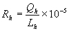 (Equation B-1)
where,
 = Hourly value of the flow-to-load ratio, scfh/megawatts, scfh/1000 lb/hr of steam, or scfh/(mmBtu/hr thermal output).
 = Hourly stack gas volumetric flow rate, as measured by the flow rate monitor, scfh.
 = Hourly unit load, megawatts, 1000 lb/hr of steam, or mmBtu/hr thermal output; must be within + 10.0 percent of
  during the most recent normal-load flow RATA.
| (1)
| In Equation B-1, the owner or operator may use either bias-adjusted flow rates or unadjusted flow rates, provided that all of the ratios are calculated the same way. For a common stack,  will be the sum of the hourly operating loads of all units that discharge through the stack. For a unit that discharges its emissions through multiple stacks or that monitors its emissions in multiple breechings, will be the sum of the hourly operating loads of all units that discharge through the stack. For a unit that discharges its emissions through multiple stacks or that monitors its emissions in multiple breechings,  will be either the combined hourly volumetric flow rate for all of the stacks or ducts (if the test is done on a unit basis) or the hourly flow rate through each stack individually (if the test is performed separately for each stack). For a unit with a multiple stack discharge configuration consisting of a main stack and a bypass stack, each of which has a certified flow monitor (e.g., a unit with a wet SO2 scrubber), calculate the hourly flow-to-load ratios separately for each stack. Round off each value of will be either the combined hourly volumetric flow rate for all of the stacks or ducts (if the test is done on a unit basis) or the hourly flow rate through each stack individually (if the test is performed separately for each stack). For a unit with a multiple stack discharge configuration consisting of a main stack and a bypass stack, each of which has a certified flow monitor (e.g., a unit with a wet SO2 scrubber), calculate the hourly flow-to-load ratios separately for each stack. Round off each value of  to two decimal places. to two decimal places. |
| |
| (2)
| Alternatively, the owner or operator may calculate the hourly gross heat rates (GHR) in lieu of the hourly flow-to-load ratios. The hourly GHR must be determined only for those hours in which quality assured flow rate data and diluent gas (CO2 or O2) concentration data are both available from a certified monitor or monitoring system or reference method. If this option is selected, calculate each hourly GHR value as follows: |
| |
 (Equation B-1a)
where,
 = Hourly value of the gross heat rate, Btu/kwh, Btu/lb steam load, or 1000 mmBtu heat input/mmBtu thermal output.
 = Hourly heat input, as determined from the quality assured flow rate and diluent data, using the applicable equation in Exhibit C to this Appendix, mmBtu/hr.
 = Hourly unit load, megawatts, 1000 lb/hr of steam, or mmBtu/hr thermal output; must be within + 10.0 percent of
  during the most recent normal-load flow RATA.
| (3)
| In Equation B-1a, the owner or operator may either use bias-adjusted flow rates or unadjusted flow rates in the calculation of  , provided that all of the heat input values are determined in the same manner. , provided that all of the heat input values are determined in the same manner. |
| |
| (4)
| The owner or operator must evaluate the calculated hourly flow-to-load ratios (or gross heat rates) as follows. A separate data analysis must be performed for each primary and each redundant backup flow rate monitor used to record and report data during the quarter. Each analysis must be based on a minimum of 168 acceptable recorded hourly average flow rates (i.e., at loads within +- 10 percent of  ). When two RATA load levels are designated as normal, the analysis must be performed at the higher load level, unless there are fewer than 168 acceptable data points available at that load level, in which case the analysis must be performed at the lower load level. If, for a particular flow monitor, fewer than 168 acceptable hourly flow-to-load ratios (or GHR values) are available at any of the load levels designated as normal, a flow-to-load (or GHR) evaluation is not required for that monitor for that calendar quarter. ). When two RATA load levels are designated as normal, the analysis must be performed at the higher load level, unless there are fewer than 168 acceptable data points available at that load level, in which case the analysis must be performed at the lower load level. If, for a particular flow monitor, fewer than 168 acceptable hourly flow-to-load ratios (or GHR values) are available at any of the load levels designated as normal, a flow-to-load (or GHR) evaluation is not required for that monitor for that calendar quarter. |
| |
| (5)
| For each flow monitor, use Equation B-2 in this Exhibit to calculate  , the absolute percentage difference between each hourly , the absolute percentage difference between each hourly  value and value and  , the reference value of the flow-to-load ratio, as determined in accordance with Section 7.7 to Appendix A to 40 CFR Part 75. Note that , the reference value of the flow-to-load ratio, as determined in accordance with Section 7.7 to Appendix A to 40 CFR Part 75. Note that  must always be based upon the most recent normal-load RATA, even if that RATA was performed in the calendar quarter being evaluated. must always be based upon the most recent normal-load RATA, even if that RATA was performed in the calendar quarter being evaluated. |
| |
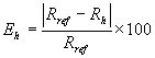 (Equation B-2)
where:
 = Absolute percentage difference between the hourly average flow-to-load ratio and the reference value of the flow-to-load ratio at normal load.
 = The hourly average flow-to-load ratio, for each flow rate recorded at a load level within +-10.0 percent of
  .
.
 = The reference value of the flow-to-load ratio from the most recent normal-load flow RATA, determined in accordance with Section 7.7 to Appendix A to 40 CFR Part 75.
| (6)
| Equation B-2 must be used in a consistent manner. That is, use  and and  if the flow-to-load ratio is being evaluated, and use (GHR)ref and (GHR) h if the gross heat rate is being evaluated. Finally, calculate if the flow-to-load ratio is being evaluated, and use (GHR)ref and (GHR) h if the gross heat rate is being evaluated. Finally, calculate  , the arithmetic average of all of the hourly , the arithmetic average of all of the hourly  values. The owner or operator must report the results of each quarterly flow-to-load (or gross heat rate) evaluation, as determined from Equation B-2, in the electronic quarterly report required under 40 CFR 75.64
. values. The owner or operator must report the results of each quarterly flow-to-load (or gross heat rate) evaluation, as determined from Equation B-2, in the electronic quarterly report required under 40 CFR 75.64
. |
| |
| (b)
| Acceptable results. The results of a quarterly flow-to-load (or gross heat rate) evaluation are acceptable, and no further action is required, if the calculated value of  is less than or equal to: (1) 15.0 percent, if is less than or equal to: (1) 15.0 percent, if  for the most recent normal-load flow RATA is >=60 megawatts (or >=500 klb/hr of steam) and if unadjusted flow rates were used in the calculations; or (2) 10.0 percent, if for the most recent normal-load flow RATA is >=60 megawatts (or >=500 klb/hr of steam) and if unadjusted flow rates were used in the calculations; or (2) 10.0 percent, if  for the most recent normal-load flow RATA is >=60 megawatts (or >=500 klb/hr of steam) and if bias-adjusted flow rates were used in the calculations; or (3) 20.0 percent, if for the most recent normal-load flow RATA is >=60 megawatts (or >=500 klb/hr of steam) and if bias-adjusted flow rates were used in the calculations; or (3) 20.0 percent, if  for the most recent normal-load flow RATA is <60 megawatts (or <500 klb/hr of steam) and if unadjusted flow rates were used in the calculations; or (4) 15.0 percent, if for the most recent normal-load flow RATA is <60 megawatts (or <500 klb/hr of steam) and if unadjusted flow rates were used in the calculations; or (4) 15.0 percent, if  for the most recent normal-load flow RATA is <60 megawatts (or <500 klb/hr of steam) and if bias-adjusted flow rates were used in the calculations. If for the most recent normal-load flow RATA is <60 megawatts (or <500 klb/hr of steam) and if bias-adjusted flow rates were used in the calculations. If  is above these limits, the owner or operator must either: implement Option 1 in Section 2.2.5.1 of this Exhibit; or perform a RATA in accordance with Option 2 in Section 2.2.5.2 of this Exhibit; or re-examine the hourly data used for the flow-to-load or GHR analysis and recalculate is above these limits, the owner or operator must either: implement Option 1 in Section 2.2.5.1 of this Exhibit; or perform a RATA in accordance with Option 2 in Section 2.2.5.2 of this Exhibit; or re-examine the hourly data used for the flow-to-load or GHR analysis and recalculate  , after excluding all non-representative hourly flow rates. If , after excluding all non-representative hourly flow rates. If  is above these limits, the owner or operator must either: implement Option 1 in Section 2.2.5.1 of this Exhibit; perform a RATA in accordance with Option 2 in Section 2.2.5.2 of this Exhibit; or (if applicable) re-examine the hourly data used for the flow-to-load or GHR analysis and recalculate is above these limits, the owner or operator must either: implement Option 1 in Section 2.2.5.1 of this Exhibit; perform a RATA in accordance with Option 2 in Section 2.2.5.2 of this Exhibit; or (if applicable) re-examine the hourly data used for the flow-to-load or GHR analysis and recalculate  , after excluding all non-representative hourly flow rates, as provided in paragraph (c) of this Section. , after excluding all non-representative hourly flow rates, as provided in paragraph (c) of this Section. |
| |
| (c)
| Recalculation of  . If the owner or operator did not exclude any hours within +-10 percent of . If the owner or operator did not exclude any hours within +-10 percent of  from the original data analysis and chooses to recalculate from the original data analysis and chooses to recalculate  , the flow rates for the following hours are considered non-representative and may be excluded from the data analysis: , the flow rates for the following hours are considered non-representative and may be excluded from the data analysis: |
| |
| (1)
| Any hour in which the type of fuel combusted was different from the fuel burned during the most recent normal-load RATA. For purposes of this determination, the type of fuel is different if the fuel is in a different state of matter (i.e., solid, liquid, or gas) than is the fuel burned during the RATA or if the fuel is a different classification of coal (e.g., bituminous versus sub-bituminous). Also, for units that co-fire different types of fuels, if the reference RATA was done while co-firing, then hours in which a single fuel was combusted may be excluded from the data analysis as different fuel hours (and vice-versa for co-fired hours, if the reference RATA was done while combusting only one type of fuel); |
| |
| (2)
| For a unit that is equipped with an SO2 scrubber and which always discharges its flue gases to the atmosphere through a single stack, any hour in which the SO2 scrubber was bypassed; |
| |
| (3)
| Any hour in which "ramping" occurred, i.e., the hourly load differed by more than +-15.0 percent from the load during the preceding hour or the subsequent hour; |
| |
| (4)
| For a unit with a multiple stack discharge configuration consisting of a main stack and a bypass stack, any hour in which the flue gases were discharged through both stacks; |
| |
| (5)
| If a normal-load flow RATA was performed and passed during the quarter being analyzed, any hour prior to completion of that RATA; and |
| |
| (6)
| If a problem with the accuracy of the flow monitor was discovered during the quarter and was corrected (as evidenced by passing the abbreviated flow-to-load test in Section 2.2.5.3 of this Exhibit), any hour prior to completion of the abbreviated flow-to-load test. |
| |
| (7)
| After identifying and excluding all non-representative hourly data in accordance with paragraphs (c)(1) through (6) of this Section, the owner or operator may analyze the remaining data a second time. At least 168 representative hourly ratios or GHR values must be available to perform the analysis; otherwise, the flow-to-load (or GHR) analysis is not required for that monitor for that calendar quarter. |
| |
| (8)
| If, after re-analyzing the data,  meets the applicable limit in paragraph (b)(1), (b)(2), (b)(3), or (b)(4) of this Section, no further action is required. If, however, meets the applicable limit in paragraph (b)(1), (b)(2), (b)(3), or (b)(4) of this Section, no further action is required. If, however,  is still above the applicable limit, data from the monitor will be declared out-of-control, beginning with the first unit operating hour following the quarter in which is still above the applicable limit, data from the monitor will be declared out-of-control, beginning with the first unit operating hour following the quarter in which  exceeded the applicable limit. Alternatively, if a probationary calibration error test is performed and passed according to Section
1.4(b)(3)(B) of this Appendix, data from the monitor may be declared conditionally valid following the quarter in which exceeded the applicable limit. Alternatively, if a probationary calibration error test is performed and passed according to Section
1.4(b)(3)(B) of this Appendix, data from the monitor may be declared conditionally valid following the quarter in which  exceeded the applicable limit. The owner or operator must then either implement Option 1 in Section 2.2.5.1 of this Exhibit or Option 2 in Section 2.2.5.2 of this Exhibit. exceeded the applicable limit. The owner or operator must then either implement Option 1 in Section 2.2.5.1 of this Exhibit or Option 2 in Section 2.2.5.2 of this Exhibit. |
| |
2.2.5.1 Option 1
Within 14 unit operating days of the end of the calendar quarter for which the  value is above the applicable limit, investigate and troubleshoot the applicable flow monitor(s). Evaluate the results of each investigation as follows:
| (a)
| If the investigation fails to uncover a problem with the flow monitor, a RATA must be performed in accordance with Option 2 in Section 2.2.5.2 of this Exhibit. |
| |
| (b)
| If a problem with the flow monitor is identified through the investigation (including the need to re-linearize the monitor by changing the polynomial coefficients or K factor(s)), data from the monitor are considered invalid back to the first unit operating hour after the end of the calendar quarter for which  was above the applicable limit. If the option to use conditional data validation was selected under Section 2.2.5(c)(8) of this Exhibit, all conditionally valid data will be invalidated, back to the first unit operating hour after the end of the calendar quarter for which was above the applicable limit. If the option to use conditional data validation was selected under Section 2.2.5(c)(8) of this Exhibit, all conditionally valid data will be invalidated, back to the first unit operating hour after the end of the calendar quarter for which  was above the applicable limit. Corrective actions must be taken. All corrective actions (e.g., non-routine maintenance, repairs, major component replacements, re-linearization of the monitor, etc.) must be documented in the operation and maintenance records for the monitor. The owner or operator then must either complete the abbreviated flow-to-load test in Section 2.2.5.3 of this Exhibit, or, if the corrective action taken has required relinearization of the flow monitor, must perform a 3-load RATA. The conditional data validation procedures in Section
1.4(b)(3)of this Appendix may be applied to the 3-load RATA. was above the applicable limit. Corrective actions must be taken. All corrective actions (e.g., non-routine maintenance, repairs, major component replacements, re-linearization of the monitor, etc.) must be documented in the operation and maintenance records for the monitor. The owner or operator then must either complete the abbreviated flow-to-load test in Section 2.2.5.3 of this Exhibit, or, if the corrective action taken has required relinearization of the flow monitor, must perform a 3-load RATA. The conditional data validation procedures in Section
1.4(b)(3)of this Appendix may be applied to the 3-load RATA. |
| |
2.2.5.2 Option 2
Perform a single-load RATA (at a load designated as normal under Section 6.5.2.1 of Exhibit A to this Appendix) of each flow monitor for which  is outside of the applicable limit. If the RATA is passed hands-off, in accordance with Section 2.3.2(c) of this Exhibit, no further action is required and the out-of-control period for the monitor ends at the date and hour of completion of a successful RATA, unless the option to use conditional data validation was selected under Section 2.2.5(c)(8) of this Exhibit. In that case, all conditionally valid data from the monitor are considered to be quality-assured, back to the first unit operating hour following the end of the calendar quarter for which the
  value was above the applicable limit. If the RATA is failed, all data from the monitor will be invalidated, back to the first unit operating hour following the end of the calendar quarter for which the
  value was above the applicable limit. Data from the monitor remain invalid until the required RATA has been passed. Alternatively, following a failed RATA and corrective actions, the conditional data validation procedures of Section
1.4(b)(3) of this Appendix may be used until the RATA has been passed. If the corrective actions taken following the failed RATA included adjustment of the polynomial coefficients or K-factor(s) of the flow monitor, a 3-level RATA is required, except as otherwise specified in Section 2.3.1.3 of this Exhibit.
value was above the applicable limit. Data from the monitor remain invalid until the required RATA has been passed. Alternatively, following a failed RATA and corrective actions, the conditional data validation procedures of Section
1.4(b)(3) of this Appendix may be used until the RATA has been passed. If the corrective actions taken following the failed RATA included adjustment of the polynomial coefficients or K-factor(s) of the flow monitor, a 3-level RATA is required, except as otherwise specified in Section 2.3.1.3 of this Exhibit.
2.2.5.3 Abbreviated Flow-to-Load Test
| (a)
| The following abbreviated flow-to-load test may be performed after any documented repair, component replacement, or other corrective maintenance to a flow monitor (except for changes affecting the linearity of the flow monitor, such as adjusting the flow monitor coefficients or K factor(s)) to demonstrate that the repair, replacement, or other maintenance has not significantly affected the monitor's ability to accurately measure the stack gas volumetric flow rate. Data from the monitoring system are considered invalid from the hour of commencement of the repair, replacement, or maintenance until either the hour in which the abbreviated flow-to-load test is passed, or the hour in which a probationary calibration error test is passed following completion of the repair, replacement, or maintenance and any associated adjustments to the monitor. If the latter option is selected, the abbreviated flow-to-load test must be completed within 168 unit operating hours of the probationary calibration error test (or, for peaking units, within 30 unit operating days, if that is less restrictive). Data from the monitor are considered to be conditionally valid (as defined in 40 CFR 72.2
, incorporated by reference in Section 225.140), beginning with the hour of the probationary calibration error test. |
| |
| (b)
| Operate the unit(s) in such a way as to reproduce, as closely as practicable, the exact conditions at the time of the most recent normal-load flow RATA. To achieve this, it is recommended that the load be held constant to within +-10.0 percent of the average load during the RATA and that the diluent gas (CO2 or O2) concentration be maintained within +-0.5 percent CO2 or O2 of the average diluent concentration during the RATA. For common stacks, to the extent practicable, use the same combination of units and load levels that were used during the RATA. When the process parameters have been set, record a minimum of six and a maximum of 12 consecutive hourly average flow rates, using the flow monitor(s) for which  was outside the applicable limit. For peaking units, a minimum of three and a maximum of 12 consecutive hourly average flow rates are required. Also record the corresponding hourly load values and, if applicable, the hourly diluent gas concentrations. Calculate the flow-to-load ratio (or GHR) for each hour in the test hour period, using Equation B-1 or B-1a. Determine was outside the applicable limit. For peaking units, a minimum of three and a maximum of 12 consecutive hourly average flow rates are required. Also record the corresponding hourly load values and, if applicable, the hourly diluent gas concentrations. Calculate the flow-to-load ratio (or GHR) for each hour in the test hour period, using Equation B-1 or B-1a. Determine  for each hourly flow- to-load ratio (or GHR), using Equation B-2 of this Exhibit and then calculate for each hourly flow- to-load ratio (or GHR), using Equation B-2 of this Exhibit and then calculate  , the arithmetic average of the Eh values. , the arithmetic average of the Eh values. |
| |
| (c)
| The results of the abbreviated flow-to-load test will be considered acceptable, and no further action is required if the value of  does not exceed the applicable limit specified in Section 2.2.5 of this Exhibit. All conditionally valid data recorded by the flow monitor will be considered quality assured, beginning with the hour of the probationary calibration error test that preceded the abbreviated flow-to-load test (if applicable). However, if does not exceed the applicable limit specified in Section 2.2.5 of this Exhibit. All conditionally valid data recorded by the flow monitor will be considered quality assured, beginning with the hour of the probationary calibration error test that preceded the abbreviated flow-to-load test (if applicable). However, if  is outside the applicable limit, all conditionally valid data recorded by the flow monitor (if applicable) will be considered invalid back to the hour of the probationary calibration error test that preceded the abbreviated flow-to-load test, and a single-load RATA is required in accordance with Section 2.2.5.2 of this Exhibit. If the flow monitor must be re-linearized, however, a 3-load RATA is required. is outside the applicable limit, all conditionally valid data recorded by the flow monitor (if applicable) will be considered invalid back to the hour of the probationary calibration error test that preceded the abbreviated flow-to-load test, and a single-load RATA is required in accordance with Section 2.2.5.2 of this Exhibit. If the flow monitor must be re-linearized, however, a 3-load RATA is required. |
| |
2.3 Semiannual and Annual Assessments
For each primary and redundant backup monitoring system, perform relative accuracy assessments either semiannually or annually, as specified in Section 2.3.1.1 or 2.3.1.2 of this Exhibit for the type of test and the performance achieved. This requirement applies as of the calendar quarter following the calendar quarter in which the monitoring system is provisionally certified. A summary chart showing the frequency with which a relative accuracy test audit must be performed, depending on the accuracy achieved, is located at the end of this Exhibit in Figure 2.
2.3.1 Relative Accuracy Test Audit (RATA)
2.3.1.1 Standard RATA Frequencies
| (a)
| Except for mercury monitoring systems, and as otherwise specified in Section 2.3.1.2 of this Exhibit, perform relative accuracy test audits semiannually, i.e., once every two successive QA operating quarters (as defined in 40 CFR 72.2
, incorporated by reference in Section 225.140) for each primary and redundant backup flow monitor, CO2 or O2 diluent monitor used to determine heat input, moisture monitoring system. For each primary and redundant backup mercury concentration monitoring system and each sorbent trap monitoring system, RATAs must be performed annually, i.e., once every four successive QA operating quarters (as defined in 40 CFR 72.2
). A calendar quarter that does not qualify as a QA operating quarter must be excluded in determining the deadline for the next RATA. No more than eight successive calendar quarters must elapse after the quarter in which a RATA was last performed without a subsequent RATA having been conducted. If a RATA has not been completed by the end of the eighth calendar quarter since the quarter of the last RATA, then the RATA must be completed within a 720 unit (or stack) operating hour grace period (as provided in Section 2.3.3 of this Exhibit) following the end of the eighth successive elapsed calendar quarter, or data from the CEMS will become invalid. |
| |
| (b)
| The relative accuracy test audit frequency of a CEMS may be reduced, as specified in Section 2.3.1.2 of this Exhibit, for primary or redundant backup monitoring systems which qualify for less frequent testing. Perform all required RATAs in accordance with the applicable procedures and provisions in Sections 6.5 through 6.5.2.2 of Exhibit A to this Appendix and Sections 2.3.1.3 and 2.3.1.4 of this Exhibit. |
| |
2.3.1.2 Reduced RATA Frequencies
Relative accuracy test audits of primary and redundant backup CO2 or O2 diluent monitors used to determine heat input, moisture monitoring systems, flow monitors may be performed annually (i.e., once every four successive QA operating quarters, rather than once every two successive QA operating quarters) if any of the following conditions are met for the specific monitoring system involved:
| (a)
| The relative accuracy during the audit of a CO2 or O2 diluent monitor used to determine heat input is <=7.5 percent; |
| |
| (b)
| The relative accuracy during the audit of a flow monitor is <=7.5 percent at each operating level tested; |
| |
| (c)
| For low flow (<=10.0 fps), as measured by the reference method during the RATA stacks/ducts, when the flow monitor fails to achieve a relative accuracy <=7.5 percent during the audit, but the monitor mean value, calculated using Equation A-7 in Exhibit A to this Appendix and converted back to an equivalent velocity in standard feet per second (fps), is within +- 1.5 fps of the reference method mean value, converted to an equivalent velocity in fps; |
| |
| (d)
| For a CO2 or O2 monitor, when the mean difference between the reference method values from the RATA and the corresponding monitor values is within +- 0.7 percent CO2 or O2; and |
| |
| (e)
| When the relative accuracy of a continuous moisture monitoring system is <= 7.5 percent or when the mean difference between the reference method values from the RATA and the corresponding monitoring system values is within +-1.0 percent H2O. |
| |
2.3.1.3 RATA Load (or Operating) Levels and Additional RATA Requirements
| (a)
| For CO2 or O2 diluent monitors used to determine heat input, mercury concentration monitoring systems, sorbent trap monitoring systems, moisture monitoring systems, the required semiannual or annual RATA tests must be done at the load level (or operating level) designated as normal under Section 6.5.2.1(d) of Exhibit A to this Appendix. If two load levels (or operating levels) are designated as normal, the required RATA(s) may be done at either load level (or operating level). |
| |
| (b)
| For flow monitors installed and bypass stacks, and for flow monitors that qualify to perform only single-level RATAs under Section 6.5.2(e) of Exhibit A to this Appendix, all required semiannual or annual relative accuracy test audits must be single-load (or single-level) audits at the normal load (or operating level), as defined in Section 6.5.2.1(d) of Exhibit A to this Appendix. |
| |
| (c)
| For all other flow monitors, the RATAs must be performed as follows: |
| |
| (1)
| An annual 2-load (or 2-level) flow RATA must be done at the two most frequently used load levels (or operating levels), as determined under Section 6.5.2.1(d) of Exhibit A to this Appendix, or (if applicable) at the operating levels determined under Section 6.5.2(e) of Exhibit A to this Appendix. Alternatively, a 3-load (or 3-level) flow RATA at the low, mid, and high load levels (or operating levels), as defined under Section 6.5.2.1(b) of Exhibit A to this Appendix, may be performed in lieu of the 2-load (or 2-level) annual RATA. |
| |
| (2)
| If the flow monitor is on a semiannual RATA frequency, 2-load (or 2-level) flow RATAs and single-load (or single-level) flow RATAs at the normal load level (or normal operating level) may be performed alternately. |
| |
| (3)
| A single-load (or single-level) annual flow RATA may be performed in lieu of the 2-load (or 2-level) RATA if the results of an historical load data analysis show that in the time period extending from the ending date of the last annual flow RATA to a date that is no more than 21 days prior to the date of the current annual flow RATA, the unit (or combination of units, for a common stack) has operated at a single load level (or operating level) (low, mid, or high), for >=85.0 percent of the time. Alternatively, a flow monitor may qualify for a single-load (or single-level) RATA if the 85.0 percent criterion is met in the time period extending from the beginning of the quarter in which the last annual flow RATA was performed through the end of the calendar quarter preceding the quarter of current annual flow RATA. |
| |
| (4)
| A 3-load (or 3-level) RATA, at the low-, mid-, and high-load levels (or operating levels), as determined under Section 6.5.2.1 of Exhibit A to this Appendix, must be performed at least once every twenty consecutive calendar quarters, except for flow monitors that are exempted from 3-load (or 3-level) RATA testing under Section 6.5.2(b) or 6.5.2(e) of Exhibit A to this Appendix. |
| |
| (5)
| A 3-load (or 3-level) RATA is required whenever a flow monitor is re-linearized, i.e., when its polynomial coefficients or K factor(s) are changed, except for flow monitors that are exempted from 3-load (or 3-level) RATA testing under Section 6.5.2(b) or 6.5.2(e) of Exhibit A to this Appendix. For monitors so exempted under Section 6.5.2(b), a single-load flow RATA is required. For monitors so exempted under Section 6.5.2(e), either a single-level RATA or a 2-level RATA is required, depending on the number of operating levels documented in the monitoring plan for the unit. |
| |
| (6)
| For all multi-level flow audits, the audit points at adjacent load levels or at adjacent operating levels (e.g., mid and high) must be separated by no less than 25.0 percent of the "range of operation," as defined in Section 6.5.2.1 of Exhibit A to this Appendix. |
| |
| (d)
| A RATA of a moisture monitoring system must be performed whenever the coefficient, K factor or mathematical algorithm determined under Section 6.5.6 of Exhibit A to this Appendix is changed. |
| |
2.3.1.4 Number of RATA Attempts
The owner or operator may perform as many RATA attempts as are necessary to achieve the desired relative accuracy test audit frequencies. However, the data validation procedures in Section 2.3.2 of this Exhibit must be followed.
2.3.2 Data Validation
| (a)
| A RATA must not commence if the monitoring system is operating out-of-control with respect to any of the daily and quarterly quality assurance assessments required by Sections 2.1 and 2.2 of this Exhibit or with respect to the additional calibration error test requirements in Section 2.1.3 of this Exhibit. |
| |
| (b)
| Each required RATA must be done according to paragraphs (b)(1), (b)(2) or (b)(3) of this Section: |
| |
| (1)
| The RATA may be done "cold," i.e., with no corrective maintenance, repair, calibration adjustments, re-linearization or reprogramming of the monitoring system prior to the test. |
| |
| (2)
| The RATA may be done after performing only the routine or non-routine calibration adjustments described in Section 2.1.3 of this Exhibit at the zero and/or upscale calibration gas levels, but no other corrective maintenance, repair, re-linearization or reprogramming of the monitoring system. Trial RATA runs may be performed after the calibration adjustments and additional adjustments within the allowable limits in Section 2.1.3 of this Exhibit may be made prior to the RATA, as necessary, to optimize the performance of the CEMS. The trial RATA runs need not be reported, provided that they meet the specification for trial RATA runs in Section
1.4(b)(3)(G)(v) of this Appendix. However, if, for any trial run, the specification in Section
(b)(3)(G)(v) of this Appendix is not met, the trial run must be counted as an aborted RATA attempt. |
| |
| (3)
| The RATA may be done after repair, corrective maintenance, re-linearization or reprogramming of the monitoring system. In this case, the monitoring system will be considered out-of-control from the hour in which the repair, corrective maintenance, re-linearization or reprogramming is commenced until the RATA has been passed. Alternatively, the data validation procedures and associated timelines in Sections
1.4(b)(3)(B) through (I)
of this Appendix may be followed upon completion of the necessary repair, corrective maintenance, re-linearization or reprogramming. If the procedures in Section 1.4
(b)(3) of this Appendix are used, the words "quality assurance" apply instead of the word "recertification." |
| |
| (c)
| Once a RATA is commenced, the test must be done hands-off. No adjustment of the monitor's calibration is permitted during the RATA test period, other than the routine calibration adjustments following daily calibration error tests, as described in Section 2.1.3 of this Exhibit. If a routine daily calibration error test is performed and passed just prior to a RATA (or during a RATA test period) and a mathematical correction factor is automatically applied by the DAHS, the correction factor must be applied to all subsequent data recorded by the monitor, including the RATA test data. For 2-level and 3- level flow monitor audits, no linearization or reprogramming of the monitor is permitted in between load levels. |
| |
| (d)
| For single-load (or single-level) RATAs, if a daily calibration error test is failed during a RATA test period, prior to completing the test, the RATA must be repeated. Data from the monitor are invalidated prospectively from the hour of the failed calibration error test until the hour of completion of a subsequent successful calibration error test. The subsequent RATA must not be commenced until the monitor has successfully passed a calibration error test in accordance with Section 2.1.3 of this Exhibit. Notwithstanding these requirements, when ASTM D6784-02 (incorporated by reference under Section 225.140) or Method 29 in appendix A-8 to 40 CFR 60, incorporated by reference in Section 225.140, is used as the reference method for the RATA of a mercury CEMS, if a calibration error test of the CEMS is failed during a RATA test period, any test run(s) completed prior to the failed calibration error test need not be repeated; however, the RATA may not continue until a subsequent calibration error test of the mercury CEMS has been passed. For multiple-load (or multiple-level) flow RATAs, each load level (or operating level) is treated as a separate RATA (i.e., when a calibration error test is failed prior to completing the RATA at a particular load level (or operating level), only the RATA at that load level (or operating level) must be repeated; the results of any previously-passed RATA(s) at the other load level(s) (or operating level(s)) are unaffected, unless re-linearization of the monitor is required to correct the problem that caused the calibration failure, in which case a subsequent 3-load (or 3-level) RATA is required), except as otherwise provided in Section 2.3.1.3(c)(5) of this Exhibit. |
| |
| (e)
| For a RATA performed using the option in paragraph (b)(1) or (b)(2) of this Section, if the RATA is failed (that is, if the relative accuracy exceeds the applicable specification in Section 3.3 of Exhibit A to this Appendix
) or if the RATA is aborted prior to completion due to a problem with the CEMS, then the CEMS is out-of-control and all emission data from the CEMS are invalidated prospectively from the hour in which the RATA is failed or aborted. Data from the CEMS remain invalid until the hour of completion of a subsequent RATA that meets the applicable specification in Section 3.3 of Exhibit A to this Appendix
. If the option in paragraph (b)(3) of this Section to use the data validation procedures and associated timelines in Sections
1.4(b)(3)(B) through(b)(3)(I) of this Appendix has been selected, the beginning and end of the out-of-control period must be determined in accordance with Section
1.4(b)(3)(G)(i) and (ii) of this Appendix. Note that when a RATA is aborted for a reason other than monitoring system malfunction (see paragraph (g) of this Section), this does not trigger an out-of-control period for the monitoring system. |
| |
| (f)
| For a 2-level or 3-level flow RATA, if, at any load level (or operating level), a RATA is failed or aborted due to a problem with the flow monitor, the RATA at that load level (or operating level) must be repeated. The flow monitor is considered out-of-control and data from the monitor are invalidated from the hour in which the test is failed or aborted and remain invalid until the passing of a RATA at the failed load level (or operating level), unless the option in paragraph (b)(3) of this Section to use the data validation procedures and associated timelines in Section
1.4(b)(3)(B) through (b)(3)(I) of this Appendix has been selected, in which case the beginning and end of the out-of-control period must be determined in accordance with Section
1.4(b)(3)(G)(i) and (ii) of this Appendix. Flow RATA(s) that were previously passed at the other load level(s) (or operating levels(s)) do not have to be repeated unless the flow monitor must be re-linearized following the failed or aborted test. If the flow monitor is re-linearized, a subsequent 3-load (or 3-level) RATA is required, except as otherwise provided in Section 2.3.1.3(c)(5) of this Exhibit. |
| |
| (g)
| For each monitoring system, report the results of all completed and partial RATAs that affect data validation (i.e., all completed, passed RATAs; all completed, failed RATAs; and all RATAs aborted due to a problem with the CEMS, including trial RATA runs counted as failed test attempts under paragraph (b)(2) of this Section or under Section
1.4(b)(3)(G)(vi)) in the quarterly report required under 40 CFR 75.64
, incorporated by reference in Section 225.140. Note that RATA attempts that are aborted or invalidated due to problems with the reference method or due to operational problems with the affected unit(s) need not be reported. Such runs do not affect the validation status of emission data recorded by the CEMS. However, a record of all RATAs, trial RATA runs and RATA attempts (whether reported or not) must be kept on-site as part of the official test log for each monitoring system. |
| |
| (h)
| Each time that a hands-off RATA of a mercury concentration monitoring system, a sorbent trap monitoring system, or a flow monitor is passed, perform a bias test in accordance with Section 7.4.4 of Exhibit A to this Appendix. |
| |
| (i)
| Failure of the bias test does not result in the monitoring system being out-of-control. |
| |
2.3.3 RATA Grace Period
| (a)
| The owner or operator has a grace period of 720 consecutive unit operating hours, as defined in 40 CFR 72.2
, incorporated by reference in Section 225.140 (or, for CEMS installed on common stacks or bypass stacks, 720 consecutive stack operating hours, as defined in 40 CFR 72.2
), in which to complete the required RATA for a particular CEMS whenever: |
| |
| (1)
| A required RATA has not been performed by the end of the QA operating quarter in which it is due; or |
| |
| (2)
| A required 3-load flow RATA has not been performed by the end of the calendar quarter in which it is due. |
| |
| (b)
| The grace period will begin with the first unit (or stack) operating hour following the calendar quarter in which the required RATA was due. Data validation during a RATA grace period must be done in accordance with the applicable provisions in Section 2.3.2 of this Exhibit. |
| |
| (c)
| If, at the end of the 720 unit (or stack) operating hour grace period, the RATA has not been completed, data from the monitoring system will be invalid, beginning with the first unit operating hour following the expiration of the grace period. Data from the CEMS remain invalid until the hour of completion of a subsequent hands-off RATA. The deadline for the next test will be either two QA operating quarters (if a semiannual RATA frequency is obtained) or four QA operating quarters (if an annual RATA frequency is obtained) after the quarter in which the RATA is completed, not to exceed eight calendar quarters. |
| |
| (d)
| When a RATA is done during a grace period in order to satisfy a RATA requirement from a previous quarter, the deadline for the next RATA must be determined as follows: |
| |
| (1)
| If the grace period RATA qualifies for a reduced, (i.e., annual), RATA frequency the deadline for the next RATA will be set at three QA operating quarters after the quarter in which the grace period test is completed. |
| |
| (2)
| If the grace period RATA qualifies for the standard, (i.e., semiannual), RATA frequency the deadline for the next RATA will be set at two QA operating quarters after the quarter in which the grace period test is completed. |
| |
| (3)
| Notwithstanding these requirements, no more than eight successive calendar quarters must elapse after the quarter in which the grace period test is completed, without a subsequent RATA having been conducted. |
| |
2.4 Recertification, Quality Assurance, and RATA Frequency (Special Considerations)
| (a)
| When a significant change is made to a monitoring system such that recertification of the monitoring system is required in accordance with Section 1.4(b)
of this Appendix, a recertification test (or tests) must be performed to ensure that the CEMS continues to generate valid data. In all recertifications, a RATA will be one of the required tests; for some recertifications, other tests will also be required. A recertification test may be used to satisfy the quality assurance test requirement of this Exhibit. For example, if, for a particular change made to a CEMS, one of the required recertification tests is a linearity check and the linearity check is successful, then, unless another such recertification event occurs in that same QA operating quarter, it would not be necessary to perform an additional linearity test of the CEMS in that quarter to meet the quality assurance requirement of Section 2.2.1 of this Exhibit. For this reason, EPA recommends that owners or operators coordinate component replacements, system upgrades, and other events that may require recertification, to the extent practicable, with the periodic quality assurance testing required by this Exhibit. When a quality assurance test is done for the dual purpose of recertification and routine quality assurance, the applicable data validation procedures in Section
1.4(b)(3) must be followed. |
| |
| (b)
| Except as provided in Section 2.3.3 of this Exhibit, whenever a passing RATA of a gas monitor is performed, or a passing 2-load (or 2-level) RATA or a passing 3-load (or 3-level) RATA of a flow monitor is performed (irrespective of whether the RATA is done to satisfy a recertification requirement or to meet the quality assurance requirements of this Exhibit, or both), the RATA frequency (semi-annual or annual) must be established based upon the date and time of completion of the RATA and the relative accuracy percentage obtained. For 2-load (or 2-level) and 3-load (or 3-level) flow RATAs, use the highest percentage relative accuracy at any of the loads (or levels) to determine the RATA frequency. The results of a single-load (or single-level) flow RATA may be used to establish the RATA frequency when the single-load (or single-level) flow RATA is specifically required under Section 2.3.1.3(b) of this Exhibit or when the single-load (or single-level) RATA is allowed under Section 2.3.1.3(c) of this Exhibit for a unit that has operated at one load level (or operating level) for >=85.0 percent of the time since the last annual flow RATA. No other single-load (or single-level) flow RATA may be used to establish an annual RATA frequency; however, a 2-load or 3-load (or a 2-level or 3-level) flow RATA may be performed at any time or in place of any required single-load (or single-level) RATA, in order to establish an annual RATA frequency. |
| |
2.5 Other Audits
Affected units may be subject to relative accuracy test audits at any time. If a monitor or continuous emission monitoring system fails the relative accuracy test during the audit, the monitor or continuous emission monitoring system will be considered to be out-of-control beginning with the date and time of completion of the audit, and continuing until a successful audit test is completed following corrective action.
2.6 System Integrity Checks for Mercury Monitors
For each mercury concentration monitoring system (except for a mercury monitor that does not have a converter), perform a single-point system integrity check weekly, i.e., at least once every 168 unit or stack operating hours, using a NIST-traceable source of oxidized mercury. Perform this check using a mid- or high-level gas concentration, as defined in Section 5.2 of Exhibit A to this Appendix. The performance specifications in paragraph (3) of Section 3.2
of Exhibit A to this Appendix must be met, otherwise the monitoring system is considered out-of-control, from the hour of the failed check until a subsequent system integrity check is passed. If a required system integrity check is not performed and passed within 168 unit or stack operating hours of last successful check, the monitoring system will also be considered out of control, beginning with the 169th unit or stack operating hour after the last successful check, and continuing until a subsequent system integrity check is passed. This weekly check is not required if the daily calibration assessments in Section 2.1.1 of this Exhibit are performed using a NIST-traceable source of oxidized mercury.
[Note: The following TABLE/FORM is too wide to be displayed on one screen. You must print it for a meaningful review of its contents. The table has been divided into multiple pieces with each piece containing information to help you assemble a printout of the table. The information for each piece includes: (1) a three line message preceding the tabular data showing by line # and character # the position of the upper left-hand corner of the piece and the position of the piece within the entire table; and (2) a numeric scale following the tabular data displaying the character positions.]
*******************************************************************************
******** This is piece 1. -- It begins at character 1 of table line 1. ********
*******************************************************************************
Figure 1 for Exhibit B of Appendix B
--------------------------------
Test
--------------------------------
Calibration Error Test (2 pt.) .
Interference Check (flow) ......
Flow-to-Load Ratio .............
Leak Check (DP flow monitors) ..
Linearity Check or System
Integrity Check [FN**] (3 pt.)
Single-point System Integrity
Check [FN**] .................
RATA (SO2, NOX, CO2, O2
H2O) [FN1] .................
RATA (All Hg monitoring systems)
RATA (flow) [FN1] [FN2] ........
--------------------------------
1...+...10....+...20....+...30..
*******************************************************************************
******* This is piece 2. -- It begins at character 33 of table line 1. ********
*******************************************************************************
Part 75.--Quality Assurance Test Requirements
------------------------------------------------------
Basic QA test frequency requirements [FN*]
--------------------------------------------------
Daily Weekly Quarterly Semiannual Annual
[FN*] [FN*] [FN*]
------------------------------------------------------
...... / ...... ........... ............ ......
...... / ...... ........... ............ ......
... ....... ...... / ............ ......
... ....... ...... / ............ ......
.. ....... ...... / ............ ......
... ....... / ........... ............ ......
... ....... ...... ........... / ......
.. ....... ...... ........... ............ /
... ....... ...... ........... / ......
------------------------------------------------------
33....40....+...50....+...60....+...70....+...80....+.
*******************************************************************************
******* This is piece 3. -- It begins at character 1 of table line 21. ********
******************************************************************************
[FN*] "Daily" means operating days, only. "Weekly" means once every 168 unit or stack operating hours. "Quarterly" means once every QA operating quarter. "Semiannual" means once every two QA operating quarters. "Annual" means once every four QA operating quarters. [FN**] The system integrity check applies only to Hg monitors with converters. The single-point weekly system integrity check is not required if daily calibrations are performed using a NIST-traceable source of oxidized Hg. The 3-point quarterly system integrity check is not required if a linearity check is performed.
[FN1] Conduct RATA annually (i.e., once every four QA operating quarters), if monitor meets accuracy requirements to qualify for less frequent testing. [FN2] For flow monitors installed on peaking units, bypass stacks, or units that qualify for single-level RATA testing under Section 6.5.2(e) of this part, conduct all RATAs at a single, normal load (or operating level). For other flow monitors, conduct annual RATAs at two load levels (or operating levels). Alternating single-load and 2-load (or single-level and 2-level) RATAs may be done if a monitor is on a semiannual frequency. A single-load (or single-level) RATA may be done in lieu of a 2-load (or 2-level) RATA if, since the last annual flow RATA, the unit has operated at one load level (or operating level) for >=85.0 percent of the time. A 3-level RATA is required at least once every five calendar years and whenever a flow monitor is re-linearized, except for flow monitors exempted from 3-level RATA testing under Section 6.5.2(b) or 6.5.2(e) of Exhibit A to this Appendix.
1...+...10....+...20....+...30....+...40....+...50....+...60....+...70....+....
Figure 2 for Exhibit B of Appendix B--Relative Accuracy Test Frequency Incentive
System
-------------------------------------------------------------------------------
RATA Semiannual [FNW] Annual [FNW]
(percent)
-------------------------------------------------------------------------------
SO2 or NOX [FNY] 7.5% <RA <=10.0% or +-15.0
ppm [FNX] .....RA <=7.5% or +-12.0 ppm
[FNX].
SO2-diluent ....... 7.5% <RA <=10.0% or +-0.030
lb/mmBtu [FNX] ........RA <=7.5% or +-0.025
lb/mmBtu =G5X.
NOX-diluent ....... 7.5% <RA <=10.0% or +-0.020
lb/mmBtu [FNX] ......RA <= 7.5% or +-0. 015
lb/mmBtu [FNX].
Flow ................ 7.5% < RA <=10.0% or +-2.0
fps [FNX] ................. RA <=7.5% or +-1.5 fps
[FNX].
CO2 or O2 ....... 7.5% < RA <=10.0% or +-1.0%
CO2/O2 [FNX] .......... RA <=7.5% or +-0.7%
CO2/O2 [FNX].
Hg [FNX] ............ N/A ......................... RA < 20.0% or +- 1.0
<<mu>>g/scm
[FNX].
Moisture ............ 7.5% <RA <=10.0% or +-1.5%
H2O [FNX] ............... RA <=7.5% or +-1.0% H2O
[FNX].
-------------------------------------------------------------------------------
[FNW] The deadline for the next RATA is the end of the second (if semiannual) or fourth (if annual) successive QA operating quarter following the quarter in which the CEMS was last tested. Exclude calendar quarters with fewer than 168 unit operating hours (or, for common stacks and bypass stacks, exclude quarters with fewer than 168 stack operating hours) in determining the RATA deadline. For SO2 monitors, QA operating quarters in which only very low sulfur fuel as defined in 40 CFR 72.2, incorporated by reference in Section 225.140, is combusted may also be excluded. However, the exclusion of calendar quarters is limited as follows: the deadline for the next RATA will be no more than 8 calendar quarters after the quarter in which a RATA was last performed. [FNX] The difference between monitor and reference method mean values applies to moisture monitors, CO2, and O2 monitors, low emitters of SO2, NOX, or Hg, or and low flow, only. The specifications for Hg monitors also apply to sorbent trap monitoring systems. [FNY] A NOX concentration monitoring system used to determine NOX mass emissions under 40 CFR 75.71, incorporated by reference in Section 225.140.
Exhibit C to Appendix B--Conversion Procedures
1. Applicability
Use the procedures in this Exhibit to convert measured data from a monitor or continuous emission monitoring system into the appropriate units of the standard.
2. Procedures for Heat Input
Use the following procedures to compute heat input rate to an affected unit (in mmBtu/hr or mmBtu/day):
2.1
Calculate and record heat input rate to an affected unit on an hourly basis. The owner or operator may choose to use the provisions specified in 40 CFR 75.16(e)
, incorporated by reference in Section 225.140, in conjunction with the procedures provided in Sections 2.4 through 2.4.2 to apportion heat input among each unit using the common stack or common pipe header.
2.2
For an affected unit that has a flow monitor (or approved alternate monitoring system under subpart E of 40 CFR 75, incorporated by reference in Section 225.140, for measuring volumetric flow rate) and a diluent gas (O2 or CO2) monitor, use the recorded data from these monitors and one of the following equations to calculate hourly heat input rate (in mmBtu/hr).
2.2.1
When measurements of CO2 concentration are on a wet basis, use the following equation:
 (Equation F - 15)
Where:
HI = Hourly heat input rate during unit operation, mmBtu/hr.
 = Hourly average volumetric flow rate during unit operation, wet basis, scfh.
 = Carbon-based F-factor, listed in Section 3.3.5 of Appendix F to 40 CFR 75 for each fuel, scf/mmBtu.
 = Hourly concentration of CO2 during unit operation, percent CO2 wet basis.
2.2.2
When measurements of CO2 concentration are on a dry basis, use the following equation:
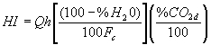 (Equation F-16)

Where:
HI = Hourly heat input rate during unit operation, mmBtu/hr.
 = Hourly average volumetric flow rate during unit operation, wet basis, scfh.
 = Carbon-based F-Factor, listed in Section 3.3.5 of Appendix F to 40 CFR 75 for each fuel, scf/mmBtu.
 = Hourly concentration of CO2 during unit operation, percent CO2 dry basis.
 = Moisture content of gas in the stack, percent.
2.2.3
When measurements of O2 concentration are on a wet basis, use the following equation:
 (Equation F-17)
Where:
HI = Hourly heat input rate during unit operation, mmBtu/hr.
 = Hourly average volumetric flow rate during unit operation, wet basis, scfh.
F = Dry basis F-factor, listed in Section 3.3.5 of Appendix F to 40 CFR 75 for each fuel, dscf/mmBtu.
 = Hourly concentration of O2 during unit operation, percent O2 wet basis.
 = Hourly average stack moisture content, percent by volume.
For any operating hour where Equation F-17 results in an hourly heat input rate that is <= 0.0 mmBtu/hr, 1.0 mmBtu/hr must be recorded and reported as the heat input rate for that hour.
2.2.4
When measurements of O2 concentration are on a dry basis, use the following equation:
 (Equation F-18)
Where:
HI = Hourly heat input rate during unit operation, mmBtu/hr.
 = Hourly average volumetric flow during unit operation, wet basis, scfh.
F = Dry basis F-factor, listed in Section 3.3.5 of Appendix F to 40 CFR 75 for each fuel, dscf/mmBtu.
 = Moisture content of the stack gas, percent.
 = Hourly concentration of O2 during unit operation, percent O2 dry basis.
2.3
Heat Input Summation (for Heat Input Determined Using a Flow Monitor and Diluent Monitor)
2.3.1
Calculate total quarterly heat input for a unit or common stack using a flow monitor and diluent monitor to calculate heat input, using the following equation:
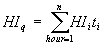 (Equation F-18a)
Where:
 = Total heat input for the quarter, mmBtu.
 = Hourly heat input rate during unit operation, using Equation F-15, F-16, F-17, or F-18, mmBtu/hr.
 = Hourly operating time for the unit or common stack, hour or fraction of an hour (in equal increments that can range from one hundredth to one quarter of an hour, at the option of the owner or operator).
2.3.2
Calculate total cumulative heat input for a unit or common stack using a flow monitor and diluent monitor to calculate heat input, using the following equation:
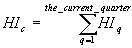 (Equation F-18b
Where:
 = Total heat input for the year to date, mmBtu.
 = Total heat input for the quarter, mmBtu.
2.4 Heat Input Rate Apportionment for Units Sharing a Common Stack or Pipe
2.4.1
Where applicable, the owner or operator of an affected unit that determines heat input rate at the unit level by apportioning the heat input monitored at a common stack or common pipe using megawatts must apportion the heat input rate using the following equation:
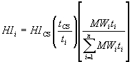 (Equation F-21a)
Where:
 = Heat input rate for a unit, mmBtu/hr.
 = Heat input rate at the common stack or pipe, mmBtu/hr.
 = Gross electrical output, MWe.
 = Unit operating time, hour or fraction of an hour (in equal increments that can range from one hundredth to one quarter of an hour, at the option of the owner or operator).
 = Common stack or common pipe operating time, hour or fraction of an hour (in equal increments that can range from one hundredth to one quarter of an hour, at the option of the owner or operator).
n = Total number of units using the common stack or pipe.
i = Designation of a particular unit.
2.4.2
Where applicable, the owner or operator of an affected unit that determines the heat input rate at the unit level by apportioning the heat input rate monitored at a common stack or common pipe using steam load must apportion the heat input rate using the following equation:
 (Equation F-21b)
Where:
 = Heat input rate for a unit, mmBtu/hr.
 = Heat input rate at the common stack or pipe, mmBtu/hr.
SF = Gross steam load, lb/hr, or mmBtu/hr.
 = Unit operating time, hour or fraction of an hour (in equal increments that can range from one hundredth to one quarter of an hour, at the option of the owner or operator).
 = Common stack or common pipe operating time, hour or fraction of an hour (in equal increments that can range from one hundredth to one quarter of an hour, at the option of the owner or operator).
n = Total number of units using the common stack or pipe.
i = Designation of a particular unit.
2.5 Heat Input Rate Summation for Units with Multiple Stacks or Pipes
The owner or operator of an affected unit that determines the heat input rate at the unit level by summing the heat input rates monitored at multiple stacks or multiple pipes must sum the heat input rates using the following equation:
 (Equation F-21c)
Where:
 = Heat input rate for a unit, mmBtu/hr.
 = Heat input rate for the individual stack, duct, or pipe, mmBtu/hr.
 = Unit operating time, hour or fraction of the hour (in equal increments that can range from one hundredth to one quarter of an hour, at the option of the owner or operator).
 = Operating time for the individual stack or pipe, hour or fraction of the hour (in equal increments that can range from one hundredth to one quarter of an hour, at the option of the owner or operator).
s = Designation for a particular stack, duct, or pipe.
3. Procedure for Converting Volumetric Flow to STP
Use the following equation to convert volumetric flow at actual temperature and pressure to standard temperature and pressure.
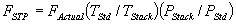 (Equation F-22)
Where:
 =Flue gas volumetric flow rate at standard temperature and pressure, scfh.
 =Flue gas volumetric flow rate at actual temperature and pressure, acfh.
 =Standard temperature=528 degreesR.
 =Flue gas temperature at flow monitor location, degreesR, where degreesR=460+degreesF.
 =The absolute flue gas pressure=barometric pressure at the flow monitor location + flue gas static pressure, inches of mercury.
 =Standard pressure=29.92 inches of mercury.
4. Procedures for Mercury Mass Emissions.
4.1
Use the procedures in this Section to calculate the hourly mercury mass emissions (in ounces) at each monitored location, for the affected unit or group of units that discharge through a common stack.
4.1.1
To determine the hourly mercury mass emissions when using a mercury concentration monitoring system that measures on a wet basis and a flow monitor, use the following equation:
 (Equation F-28)
Where:
 = Mercury mass emissions for the hour, rounded off to three decimal places, (ounces).
K = Units conversion constant, 9.978 x 10⁻¹⁰ oz-scm/µg-scf
 = Hourly mercury concentration, wet basis, adjusted for bias if the bias-test procedures in Exhibit A to this Appendix show that a bias-adjustment factor is necessary, (µg/wscm).
 = Hourly stack gas volumetric flow rate, adjusted for bias, where the bias-test procedures in Exhibit A to this Appendix shows a bias-adjustment factor is necessary, (scfh)
 = Unit or stack operating time, as defined in 40 CFR 72.2
, (hr)
= Unit or stack operating time, as defined in 40 CFR 72.2
, (hr)
4.1.2
To determine the hourly mercury mass emissions when using a mercury concentration monitoring system that measures on a dry basis or a sorbent trap monitoring system and a flow monitor, use the following equation:
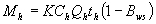 (Equation F-29)
Where:
 = mercury mass emissions for the hour, rounded off to three decimal places, (ounces).
K = Units conversion constant, 9.978 x 10⁻¹⁰ oz-scm/<<mu>>g-scf
 = Hourly mercury concentration, dry basis, adjusted for bias if the bias-test procedures in Exhibit A to this Appendix show that a bias-adjustment factor is necessary, (µg/dscm). For sorbent trap systems, a single value of
  (i.e., a flow-proportional average concentration for the data collection period), is applied to each hour in the data collection period, for a particular pair of traps.
 = Hourly stack gas volumetric flow rate, adjusted for bias, where the bias-test procedures in Exhibit A to this Appendix shows a bias-adjustment factor is necessary, (scfh)
 = Moisture fraction of the stack gas, expressed as a decimal (equal to
  100)
100)
 = Unit or stack operating time, as defined in 40 CFR 72.2
, (hr)
= Unit or stack operating time, as defined in 40 CFR 72.2
, (hr)
4.1.3
For units that are demonstrated under Section 1.15(d)
of this Appendix to emit less than 464 ounces of mercury per year, and for which the owner or operator elects not to continuously monitor the mercury concentration, calculate the hourly mercury mass emissions using Equation F-28 in Section 4.1.1 of this Exhibit, except that " " will be the applicable default mercury concentration from Section 1.15(c)
, (d)
, or (e)
of this Appendix, expressed in µg/scm. Correction for the stack gas moisture content is not required when this methodology is used.
" will be the applicable default mercury concentration from Section 1.15(c)
, (d)
, or (e)
of this Appendix, expressed in µg/scm. Correction for the stack gas moisture content is not required when this methodology is used.
4.2
Use the following equation to calculate quarterly and year-to-date mercury mass emissions in ounces:
 (Equation F-30)
Where:
 = Mercury mass emissions for the given time period i.e., quarter or year-to-date, rounded to the nearest thousandth, (ounces).
 = Mercury mass emissions for the hour, rounded to three decimal places, (ounces).
n = The number of hours in the given time period (quarter or year-to-date).
4.3 If heat input rate monitoring is required, follow the applicable procedures for heat input apportionment and summation in Sections 2.3, 2.4 and 2.5 of this Exhibit.
5. Moisture Determination From Wet and Dry O2 Readings
If a correction for the stack gas moisture content is required in any of the emissions or heat input calculations described in this Exhibit, and if the hourly moisture content is determined from wet- and dry-basis O2 readings, use Equation F-31 to calculate the percent moisture, unless a "K" factor or other mathematical algorithm is developed as described in Section 6.5.6(a) of Exhibit A to this Appendix:
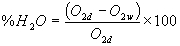 (Equation F-31)
Where:
 = Hourly average stack gas moisture content, percent H2O
 = Dry-basis hourly average oxygen concentration, percent O2
 = Wet-basis hourly average oxygen concentration, percent O2
Exhibit D to Appendix B--Quality Assurance and Operating Procedures for Sorbent Trap Monitoring Systems
1.0 Scope and Application
This Exhibit specifies sampling, and analytical, and quality-assurance criteria and procedures for the performance-based monitoring of vapor-phase mercury (Hg) emissions in combustion flue gas streams, using a sorbent trap monitoring system (as defined in Section 225.130). The principle employed is continuous sampling using in-stack sorbent media coupled with analysis of the integrated samples. The performance-based approach of this Exhibit allows for use of various suitable sampling and analytical technologies while maintaining a specified and documented level of data quality through performance criteria. Persons using this Exhibit should have a thorough working knowledge of Methods 1, 2, 3, 4 and 5 in appendices A-1 through A-3 to 40 CFR 60, incorporated by reference in Section 225.140, as well as the determinative technique selected for analysis.
1.1 Analytes.
The analyte measured by these procedures and specifications is total vapor-phase mercury in the flue gas, which represents the sum of elemental mercury (Hg0, CAS Number 7439-97-6) and oxidized forms of mercury, in mass concentration units of micrograms per dry standard cubic meter (µg/dscm).
1.2 Applicability.
These performance criteria and procedures are applicable to monitoring of vapor-phase mercury emissions under relatively low-dust conditions (i.e., sampling in the stack after all pollution control devices), from coal-fired electric utility steam generators which are subject to Sections 1.14 through 1.18 of Appendix B. Individual sample collection times can range from 30 minutes to several days in duration, depending on the mercury concentration in the stack. The monitoring system must achieve the performance criteria specified in Section 8
of this Exhibit and the sorbent media capture ability must not be exceeded. The sampling rate must be maintained at a constant proportion to the total stack flow rate to ensure representativeness of the sample collected. Failure to achieve certain performance criteria will result in invalid mercury emissions monitoring data.
2.0 Principle.
Known volumes of flue gas are extracted from a stack or duct through paired, in-stack, pre-spiked sorbent media traps at an appropriate nominal flow rate. Collection of mercury on the sorbent media in the stack mitigates potential loss of mercury during transport through a probe/sample line. Paired train sampling is required to determine measurement precision and verify acceptability of the measured emissions data.
The sorbent traps are recovered from the sampling system, prepared for analysis, as needed, and analyzed by any suitable determinative technique that can meet the performance criteria. A section of each sorbent trap is spiked with Hg0 prior to sampling. This section is analyzed separately and the recovery value is used to correct the individual mercury sample for measurement bias.
3.0 Clean Handling and Contamination.
To avoid mercury contamination of the samples, special attention should be paid to cleanliness during transport, field handling, sampling, recovery, and laboratory analysis, as well as during preparation of the sorbent cartridges. Collection and analysis of blank samples (field, trip, lab) is useful in verifying the absence of contaminant mercury.
4.0 Safety.
4.1 Site hazards.
Site hazards must be thoroughly considered in advance of applying these procedures/specifications in the field; advance coordination with the site is critical to understand the conditions and applicable safety policies. At a minimum, portions of the sampling system will be hot, requiring appropriate gloves, long sleeves, and caution in handling this equipment.
4.2 Laboratory safety policies.
Laboratory safety policies should be in place to minimize risk of chemical exposure and to properly handle waste disposal. Personnel must wear appropriate laboratory attire according to a Chemical Hygiene Plan established by the laboratory.
4.3 Toxicity or carcinogenicity.
The toxicity or carcinogenicity of any reagents used must be considered. Depending upon the sampling and analytical technologies selected, this measurement may involve hazardous materials, operations, and equipment and this Exhibit does not address all of the safety problems associated with implementing this approach. It is the responsibility of the user to establish appropriate safety and health practices and determine the applicable regulatory limitations prior to performance. Any chemical should be regarded as a potential health hazard and exposure to these compounds should be minimized. Chemists should refer to the Material Safety Data Sheet (MSDS) for each chemical used.
4.4 Wastes.
Any wastes generated by this procedure must be disposed of according to a hazardous materials management plan that details and tracks various waste streams and disposal procedures.
5.0 Equipment and Supplies.
The following list is presented as an example of key equipment and supplies likely required to perform vapor-phase mercury monitoring using a sorbent trap monitoring system. It is recognized that additional equipment and supplies may be needed. Collection of paired samples is required. Also required are a certified stack gas volumetric flow monitor that meets the requirements of Section 1.2 to this Appendix and an acceptable means of correcting for the stack gas moisture content, i.e., either by using data from a certified continuous moisture monitoring system or by using an approved default moisture value (see 40 CFR 75.11(b)
, incorporated by reference in Section 225.140).
5.1 Sorbent Trap Monitoring System.
A typical sorbent trap monitoring system is shown in Figure K-1. The monitoring system must include the following components:
5.1.1 Sorbent Traps.
The sorbent media used to collect mercury must be configured in a trap with three distinct and identical segments or sections, connected in series, that are amenable to separate analyses. Section 1
is designated for primary capture of gaseous mercury. Section 2
is designated as a backup section for determination of vapor-phase mercury breakthrough. Section 3
is designated for QA/QC purposes where this section must be spiked with a known amount of gaseous Hg0 prior to sampling and later analyzed to determine recovery efficiency. The sorbent media may be any collection material (e.g., carbon, chemically-treated filter, etc.) capable of quantitatively capturing and recovering for subsequent analysis, all gaseous forms of mercury for the intended application. Selection of the sorbent media must be based on the material's ability to achieve the performance criteria contained in Section 8
of this Exhibit as well as the sorbent's vapor-phase mercury capture efficiency for the emissions matrix and the expected sampling duration at the test site. The sorbent media must be obtained from a source that can demonstrate the quality assurance and control necessary to ensure consistent reliability. The paired sorbent traps are supported on a probe (or probes) and inserted directly into the flue gas stream.
5.1.2 Sampling Probe Assembly.
Each probe assembly must have a leak-free Exhibit to the sorbent trap(s). Each sorbent trap must be mounted at the entrance of or within the probe such that the gas sampled enters the trap directly. Each probe/sorbent trap assembly must be heated to a temperature sufficient to prevent liquid condensation in the sorbent trap(s). Auxiliary heating is required only where the stack temperature is too low to prevent condensation. Use a calibrated thermocouple to monitor the stack temperature. A single probe capable of operating the paired sorbent traps may be used. Alternatively, individual probe/sorbent trap assemblies may be used, provided that the individual sorbent traps are co-located to ensure representative mercury monitoring and are sufficiently separated to prevent aerodynamic interference.
5.1.3 Moisture Removal Device
A robust moisture removal device or system, suitable for continuous duty (such as a Peltier cooler), must be used to remove water vapor from the gas stream prior to entering the gas flow meter.
5.1.4 Vacuum Pump.
Use a leak-tight, vacuum pump capable of operating within the candidate system's flow range.
5.1.5 Gas Flow Meter
A gas flow meter (such as a dry gas meter, thermal mass flow meter, or other suitable measurement device) must be used to determine the total sample volume on a dry basis, in units of standard cubic meters. The meter must be sufficiently accurate to measure the total sample volume to within 2 percent and must be calibrated at selected flow rates across the range of sample flow rates at which the sorbent trap monitoring system typically operates. The gas flow meter must be equipped with any necessary auxiliary measurement devices (e.g., temperature sensors, pressure measurement devices) needed to correct the sample volume to standard conditions.
5.1.6 Sample Flow Rate Meter and Controller.
Use a flow rate indicator and controller for maintaining necessary sampling flow rates.
5.1.7 Temperature Sensor.
Same as Section 6.1.1.7 of Method 5 in appendix A-3 to 40 CFR 60, incorporated by reference in Section 225.140.
5.1.8 Barometer.
Same as Section 6.1.2 of Method 5 in appendix A-3 to 40 CFR 60, incorporated by reference in Section 225.140.
5.1.9 Data Logger (Optional).
Device for recording associated and necessary ancillary information (e.g., temperatures, pressures, flow, time, etc.).
5.2 Gaseous Hg0 Sorbent Trap Spiking System.
A known mass of gaseous Hg0 must be spiked onto section 3
of each sorbent trap prior to sampling. Any approach capable of quantitatively delivering known masses of Hg0 onto sorbent traps is acceptable. Several technologies or devices are available to meet this objective. Their practicality is a function of mercury mass spike levels. For low levels, NIST-certified or NIST-traceable gas generators or tanks may be suitable, but will likely require long preparation times. A more practical, alternative system, capable of delivering almost any mass required, makes use of NIST-certified or NIST-traceable mercury salt solutions (e.g., Hg(NO3)2). With this system, an aliquot of known volume and concentration is added to a reaction vessel containing a reducing agent (e.g., stannous chloride); the mercury salt solution is reduced to Hg0 and purged onto section 3 of the sorbent trap using an impinger sparging system.
5.3 Sample Analysis Equipment.
Any analytical system capable of quantitatively recovering and quantifying total gaseous mercury from sorbent media is acceptable provided that the analysis can meet the performance criteria in Section 8
of this procedure. Candidate recovery techniques include leaching, digestion, and thermal desorption. Candidate analytical techniques include ultraviolet atomic fluorescence (UV AF); ultraviolet atomic absorption (UV AA), with and without gold trapping; and in situ X-ray fluorescence (XRF) analysis.
6.0 Reagents and Standards.
Only NIST-certified or NIST-traceable calibration gas standards and reagents must be used for the tests and procedures required under this Exhibit.
7.0 Sample Collection and Transport.
7.1 Pre-Test Procedures.
7.1.1 Selection of Sampling Site.
Sampling site information should be obtained in accordance with Method 1 in appendix A-1 to 40 CFR 60, incorporated by reference in Section 225.140. Identify a monitoring location representative of source mercury emissions. Locations shown to be free of stratification through measurement traverses for gases such as SO2 and NOx may be one such approach. An estimation of the expected stack mercury concentration is required to establish a target sample flow rate, total gas sample volume, and the mass of Hg0 to be spiked onto section 3
of each sorbent trap.
7.1.2 Pre-sampling Spiking of Sorbent Traps.
Based on the estimated mercury concentration in the stack, the target sample rate and the target sampling duration, calculate the expected mass loading for section 1
of each sorbent trap (for an example calculation, see Section 11.1
of this Exhibit). The pre-sampling spike to be added to section 3
of each sorbent trap must be within +- 50 percent of the expected section 1
mass loading. Spike section 3
of each sorbent trap at this level, as described in Section 5.2 of this Exhibit. For each sorbent trap, keep an official record of the mass of Hg0 added to section 3
. This record must include, at a minimum, the ID number of the trap, the date and time of the spike, the name of the analyst performing the procedure, the mass of Hg0 added to section 3 of the trap (µg), and the supporting calculations. This record must be maintained in a format suitable for inspection and audit and must be made available to the regulatory agencies upon request.
7.1.3 Pre-test Leak Check
Perform a leak check with the sorbent traps in place. Draw a vacuum in each sample train. Adjust the vacuum in the sample train to mercury. Using the gas flow meter, determine leak rate. The leakage rate must not exceed 4 percent of the target sampling rate. Once the leak check passes this criterion, carefully release the vacuum in the sample train then seal the sorbent trap inlet until the probe is ready for insertion into the stack or duct.
7.1.4 Determination of Flue Gas Characteristics.
Determine or measure the flue gas measurement environment characteristics (gas temperature, static pressure, gas velocity, stack moisture, etc.) in order to determine ancillary requirements such as probe heating requirements (if any), initial sample rate, proportional sampling conditions, moisture management, etc.
7.2 Sample Collection.
7.2.1
Remove the plug from the end of each sorbent trap and store each plug in a clean sorbent trap storage container. Remove the stack or duct port cap and insert the probe(s). Secure the probe(s) and ensure that no leakage occurs between the duct and environment.
7.2.2
Record initial data including the sorbent trap ID, start time, starting dry gas meter readings, initial temperatures, set-points, and any other appropriate information.
7.2.3 Flow Rate Control
Set the initial sample flow rate at the target value from Section 7.1.1 of this Exhibit. Record the initial gas flow meter reading, stack temperature (if needed to convert to standard conditions), meter temperatures (if needed), etc. Then, for every operating hour during the sampling period, record the date and time, the sample flow rate, the gas flow meter reading, the stack temperature (if needed), the flow meter temperatures (if needed), temperatures of heated equipment such as the vacuum lines and the probes (if heated), and the sampling system vacuum readings. Also, record the stack gas flow rate, as measured by the certified flow monitor, and the ratio of the stack gas flow rate to the sample flow rate. Adjust the sampling flow rate to maintain proportional sampling, i.e., keep the ratio of the stack gas flow rate to sample flow rate constant, to within +-25 percent of the reference ratio from the first hour of the data collection period (see Section 11
of this Exhibit). The sample flow rate through a sorbent trap monitoring system during any hour (or portion of an hour) in which the unit is not operating must be zero.
7.2.4 Stack Gas Moisture Determination.
Determine stack gas moisture using a continuous moisture monitoring system, as described in 40 CFR 75.11(b)
, incorporated by reference in Section 225.140. Alternatively, the owner or operator may use the appropriate fuel-specific moisture default value provided in 40 CFR 75.11
, incorporated by reference in Section 225.140, or a site-specific moisture default value approved by the Agency.
7.2.5 Essential Operating Data
Obtain and record any essential operating data for the facility during the test period, e.g., the barometric pressure for correcting the sample volume measured by a dry gas meter to standard conditions. At the end of the data collection period, record the final gas flow meter reading and the final values of all other essential parameters.
7.2.6 Post Test Leak Check.
When sampling is completed, turn off the sample pump, remove the probe/sorbent trap from the port and carefully re-plug the end of each sorbent trap. Perform a leak check with the sorbent traps in place, at the maximum vacuum reached during the sampling period. Use the same general approach described in Section 7.1.3 of this Exhibit. Record the leakage rate and vacuum. The leakage rate must not exceed 4 percent of the average sampling rate for the data collection period. Following the leak check, carefully release the vacuum in the sample train.
7.2.7 Sample Recovery.
Recover each sampled sorbent trap by removing it from the probe, sealing both ends. Wipe any deposited material from the outside of the sorbent trap. Place the sorbent trap into an appropriate sample storage container and store/preserve in appropriate manner.
7.2.8 Sample Preservation, Storage, and Transport.
While the performance criteria of this approach provide for verification of appropriate sample handling, it is still important that the user consider, determine, and plan for suitable sample preservation, storage, transport, and holding times for these measurements. Therefore, procedures in ASTM D6911-03 "Standard Guide for Packaging and Shipping Environmental Samples for Laboratory Analysis" (incorporated by reference under Section 225.140) must be followed for all samples.
7.2.9 Sample Custody.
Proper procedures and documentation for sample chain of custody are critical to ensuring data integrity. The chain of custody procedures in ASTM D4840-99 (reapproved 2004) "Standard Guide for Sample Chain-of-Custody Procedures" (incorporated by reference under Section 225.140) must be followed for all samples (including field samples and blanks).
8.0 Quality Assurance and Quality Control.
Table K-1 summarizes the QA/QC performance criteria that are used to validate the mercury emissions data from sorbent trap monitoring systems, including the relative accuracy test audit (RATA) requirement (see Section 1.4(c)
(7), Section 6.5.6 of Exhibit A to this Appendix, and Section 2.3 of Exhibit B to this Appendix). Except as provided in Section 1.3(h)
of this Appendix and as otherwise indicated in Table K-1, failure to achieve these performance criteria will result in invalidation of mercury emissions data.
Table K-1.--Quality Assurance/Quality Control Criteria for Sorbent Trap
Monitoring Systems
-------------------------------------------------------------------------------
QA/QC test or Acceptance criteria Frequency Consequences if
specification not met
-------------------------------------------------------------------------------
Pre-test leak
check .......... <=4% of target sampling
rate ................. Prior to
sampling ..... Sampling must not
commence until
the leak check
is passed.
Post-test leak
check .......... <=4% of average
sampling rate ........ After sampling . [FN**] See Note,
below.
Ratio of stack
gas flow rate
to sample flow
rate ........... No more than 5% of the
hourly ratios or 5
hourly ratios
(whichever is less
restrictive) may
deviate from the
reference ratio by
more than +-% ........ Every hour
throughout
data
collection
period ....... [FN**] See Note,
below.
Sorbent trap
section 2
break-through .. <=5% of Section 1 Hg
mass ................. Every sample ... [FN**] See Note,
below.
Paired sorbent
trap agreement . <=10% Relative
Deviation (RD) if the
average concentration
is > 1.0 <<mu>>g/m3 ...Every sample ... Either invalidate
the data from
the paired traps
or report the
results from the
trap with the
higher Hg
concentration.
<= 20% RD if the
average concentration
is <= 1.0 <<mu>>g/m3
Results are also
acceptable if
absolute difference
between
concentrations from
paired traps is <=
0.03 <<mu>>g/m3
Spike Recovery
Study .......... Average recovery
between 85% and 115%
for each of the 3
spike concentration
levels ............... Prior to
analyzing
field samples
and prior to
use of new
sorbent media Field samples
must not be
analyzed until
the percent
recovery
criteria has
been met
Multipoint
analyzer
calibration .... Each analyzer reading
within +-10% of true
value and r2 >=
0.99 ................. On the day of
analysis,
before
analyzing any
samples ...... Recalibrate until
successful.
Analysis of
independent
calibration
standard ....... Within +- 10% of true
value ................ Following daily
calibration,
prior to
analyzing
field samples Recalibrate and
repeat
independent
standard
analysis until
successful.
Spike recovery
from section 3
of sorbent trap 75-125% of spike amount Every sample ... [FN**] See Note,
below.
RATA ............. RA <= 20.0% or Mean
difference <= 1.0
<<mu>>g/dscm for low
emitters ............. For initial
certification
and annually
thereafter ... Data from the
system are
invalidated
until a RATA is
passed.
Gas flow meter
calibration .... Calibration factor (Y)
within +- 5% of
average value from
the most recent
3-point calibration .. At three
settings
prior to
initial use
and at least
quarterly at
one setting
thereafter.
For mass flow
meters,
initial
calibration
with stack
gas is
required ..... Recalibrate the
meter at three
orifice settings
to determine a
new value of Y.
Temperature
sensor
calibration .... Absolute temperature
measured by sensor
within +- 1.5% of a
reference sensor ..... Prior to
initial use
and at least
quarterly
thereafter ... Recalibrate.
Sensor may not
be used until
specification is
met.
Barometer
calibration .... Absolute pressure
measured by
instrument within +-
10 mm Hg of reading
with a mercury
barometer ............ Prior to
initial use
and at least
quarterly
thereafter ... Recalibrate.
Instrument may
not be used
until
specification is
met.
-------------------------------------------------------------------------------
[FN**] Note: If both traps fail to meet the acceptance criteria, the data from the pair of traps are invalidated. However, if only one of the paired traps fails to meet this particular acceptance criterion and the other sample meets all of the applicable QA criteria, the results of the valid trap may be used for reporting under this part, provided that the measured Hg concentration is
multiplied by a factor of 1.111. When the data from both traps are invalidated and quality-assured data from a certified backup monitoring system, reference method, or approved alternative monitoring system are unavailable, missing data substitution must be used. 9.0 Calibration and Standardization.
9.1
Only NIST-certified and NIST-traceable calibration standards (i.e., calibration gases, solutions, etc.) must be used for the spiking and analytical procedures in this Exhibit.
9.2 Gas Flow Meter Calibration
9.2.1
Preliminaries. The manufacturer or supplier of the gas flow meter should perform all necessary set-up, testing, programming, etc., and should provide the end user with any necessary instructions, to ensure that the meter will give an accurate readout of dry gas volume in standard cubic meters for the particular field application.
9.2.2
Initial Calibration. Prior to its initial use, a calibration of the flow meter must be performed. The initial calibration may be done by the manufacturer, by the equipment supplier, or by the end user. If the flow meter is volumetric in nature (e.g., a dry gas meter), the manufacturer, equipment supplier, or end user may perform a direct volumetric calibration using any gas. For a mass flow meter, the manufacturer, equipment supplier, or end user may calibrate the meter using a bottled gas mixture containing 12 +- 0.5% CO2, 7 +- 0.5% O2, and balance N2, or these same gases in proportions more representative of the expected stack gas composition. Mass flow meters may also be initially calibrated on-site, using actual stack gas.
9.2.2.1
Initial Calibration Procedures. Determine an average calibration factor (Y) for the gas flow meter, by calibrating it at three sample flow rate settings covering the range of sample flow rates at which the sorbent trap monitoring system typically operates. You may either follow the procedures in Section 10.3.1 of Method 5 in appendix A-3 to 40 CFR 60, incorporated by reference in Section 225.140, or the procedures in Section 16
of Method 5 in appendix A-3 to 40 CFR 60. If a dry gas meter is being calibrated, use at least five revolutions of the meter at each flow rate.
9.2.2.2
Alternative Initial Calibration Procedures. Alternatively, you may perform the initial calibration of the gas flow meter using a reference gas flow meter (RGFM). The RGFM may either be: (1) A wet test meter calibrated according to Section 10.3.1 of Method 5 in appendix A-3 to 40 CFR 60, incorporated by reference in Section 225.140; (2) a gas flow metering device calibrated at multiple flow rates using the procedures in Section 16
of Method 5 in appendix A-3 to 40 CFR 60; or (3) a NIST-traceable calibration device capable of measuring volumetric flow to an accuracy of 1 percent. To calibrate the gas flow meter using the RGFM, proceed as follows: While the sorbent trap monitoring system is sampling the actual stack gas or a compressed gas mixture that simulates the stack gas composition (as applicable), connect the RGFM to the discharge of the system. Care should be taken to minimize the dead volume between the sample flow meter being tested and the RGFM. Concurrently measure dry gas volume with the RGFM and the flow meter being calibrated the for a minimum of 10 minutes at each of three flow rates covering the typical range of operation of the sorbent trap monitoring system. For each 10-minute (or longer) data collection period, record the total sample volume, in units of dry standard cubic meters (dscm), measured by the RGFM and the gas flow meter being tested.
9.2.2.3
Initial Calibration Factor. Calculate an individual calibration factor Yi at each tested flow rate from Section 9.2.2.1 or 9.2.2.2 of this Exhibit (as applicable), by taking the ratio of the reference sample volume to the sample volume recorded by the gas flow meter. Average the three Yi values, to determine Y, the calibration factor for the flow meter. Each of the three individual values of Yi must be within +-0.02 of Y. Except as otherwise provided in Sections 9.2.2.4 and 9.2.2.5 of this Exhibit, use the average Y value from the three level calibration to adjust all subsequent gas volume measurements made with the gas flow meter.
9.2.2.4
Initial On-Site Calibration Check. For a mass flow meter that was initially calibrated using a compressed gas mixture, an on-site calibration check must be performed before using the flow meter to provide data for this part. While sampling stack gas, check the calibration of the flow meter at one intermediate flow rate typical of normal operation of the monitoring system. Follow the basic procedures in Section 9.2.2.1 or 9.2.2.2 of this Exhibit. If the on-site calibration check shows that the value of Yi, the calibration factor at the tested flow rate, differs by more than 5 percent from the value of Y obtained in the initial calibration of the meter, repeat the full 3-level calibration of the meter using stack gas to determine a new value of Y, and apply the new Y value to all subsequent gas volume measurements made with the gas flow meter.
9.2.2.5
Ongoing Quality Assurance. Recalibrate the gas flow meter quarterly at one intermediate flow rate setting representative of normal operation of the monitoring system. Follow the basic procedures in Section 9.2.2.1 or 9.2.2.2 of this Exhibit. If a quarterly recalibration shows that the value of Yi, the calibration factor at the tested flow rate, differs from the current value of Y by more than 5 percent, repeat the full 3-level calibration of the meter to determine a new value of Y, and apply the new Y value to all subsequent gas volume measurements made with the gas flow meter.
9.3 Thermocouples and Other Temperature Sensors.
Use the procedures and criteria in Section 10.3
of Method 2 in appendix A-1 to 40 CFR 60, incorporated by reference in Section 225.140, to calibrate in-stack temperature sensors and thermocouples. Dial thermometers must be calibrated against mercury-in-glass thermometers. Calibrations must be performed prior to initial use and at least quarterly thereafter. At each calibration point, the absolute temperature measured by the temperature sensor must agree to within +- 1.5 percent of the temperature measured with the reference sensor, otherwise the sensor may not continue to be used.
9.4 Barometer.
Calibrate against a mercury barometer. Calibration must be performed prior to initial use and at least quarterly thereafter. At each calibration point, the absolute pressure measured by the barometer must agree to within +- 10 mm mercury of the pressure measured by the mercury barometer, otherwise the barometer may not continue to be used.
9.5 Other Sensors and Gauges.
Calibrate all other sensors and gauges according to the procedures specified by the instrument manufacturer(s).
9.6 Analytical System Calibration.
See Section 10.1
of this Exhibit.
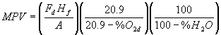 (Equation A-3a)
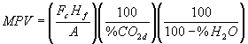 (Equation A-3b)