| | - APPENDIX?A
- HYDRAULIC?TECHNICAL?MEMORANDUM
- DISINFECTION?COST?STUDY
- HYDRAULIC?EVALUATION
- METROPOLITAN?WATER?RECLAMATION
- DISTRICT?OF?GREATER?CHICAGO
- NORTH?SIDE?WATER?RECLAMATION?PLANT
- TECHNICAL?MEMORANDUM
- OCTOBER?23,?2007
- 303?EAST?WACKER?DRIVE,?SUITE?600
- CHICAGO,?ILLINOIS?60601
- MWRDGC?Project?No.?07-026-2P
- CTE?Project?No.?60026610
- TABLE?OF?CONTENTS
- LIST?OF?TABLES
- LIST?OF?FIGURES
- LIST?OF?APPENDICES
- 1 INTRODUCTION
- 1.1?? Objective
- 2.1.1?Incorporation?into?Master?Plan
- Table?1?–?Theoretical?WSE?Assuming?All?Gravity?Flow
- Existing?Site
- Batteries?A-F
- Proposed
- Battery?E
- Figure?2?–?Alternative?1-Gravity?Influent?Battery?E,?450?MGD?LLPS?U/S?of
- Disinfection
- Figure?3?–Alternative?3?Intermediate.?P.S.?Battery?E,?LLPS?450?MGD?D/S?of
- Disinfection
- Figure?3?–?Alternative?2?Intermediate.?P.S.?Battery?E,?LLPS?345?MGD?U/S?of
- Disinfection
- 3 HYDRAULIC?ANALYSIS?OF?THE?UV?DISINFECTION?FACILITIES
- Table?2?–?Summary?of?Headloss?through?NSWRP?(Proposed)
- Battery?E
- Table?4?–?Low?Lift?Pump?Station?Basis?of?Design
- Pumps
- Wet?Well
- Table?5?–?Summary?of?Pump?Operation
- Flow,?MGD Pump?Drive?Type Pump?Flow,?gpm
- APPENDIX?A
- Selected?Pages?from?USACE?CUP?DDR
- APPENDIX?BLLPS?Proposed?Layout
- APPENDIX?B
- UV?TECHNOLOGY?TECHNICAL?MEMORANDUM
- DISINFECTION?COST?STUDYULTRAVIOLET?DISINFECTION?TECHNOLOGY
- EVALUATION
- METROPOLITAN?WATER?RECLAMATION
- DISTRICT?OF?GREATER?CHICAGO
- NORTH?SIDE?WATER?RECLAMATION?PLANT
- TECHNICAL?MEMORANDUM
- OCTOBER?23,?2007
- TABLE?OF?CONTENTS
- LIST?OF?TABLES
- LIST?OF?FIGURES
- LIST?OF?APPENDICES
- Appendix Content
- INTRODUCTION
- Background
- Objective
- AVAILABLE?UV?DISINFECTION?TECHNOLOGIES
- Figure?1?–?Categories?of?Currently?Available?UV?Disinfection?Systems?(Hunter,?et
- al.,?2006b)
- Low?Pressure?–?Low?Intensity?(LP-LI)
- Open?ChannelHorizontal
- Lamps?parallel?to?flow
- Closed?Channel
- Horizontal
- Lamps
- perpendicular?to
- HorizontalLamps?parallel?to?flow
- Vertical
- Horizontal Vertical
- Table?1?–?Typical?UV?Technology?Categories?(Bazzazieh,?2005)
- UV?System Low?Pressure,
- Low?Intensity
- Low?Pressure,High?Intensity
- Medium?Pressure,High?Intensity
- Low?Pressure?–?High?Intensity?(LP-HI)
- Medium?Pressure?–?High?Intensity?(MP-HI)
- LITERATURE?REVIEW?OF?SELECTED?MP-HI?UV?TECHNOLOGY
- Typical?MP-HI?System?Configuration
- Influent?Characteristics
- Reactor?Configuration?and?Hydraulics
- Lamps?and?UV?Intensity?Control
- Lamp?Fouling?and?Cleaning
- Process?Control
- Safety
- REVIEW?OF?AVAILABLE?TECHNOLOGIES?FROM?MANUFACTURERS
- Trojan?Technologies?–?Trojan?UV4000™Plus
- Figure?2?–?UV4000+?System(Courtesy?of?Trojan?Technologies)
- Aquionics?–?InLine50,000+
- Figure?3?–?InLine50,000+?System
- (Courtesy?of?Aquionics)
- Calgon?Carbon?–?C
- 3500™
- Figure?4?–?TAK25?System
- (Courtesy?of?ITT/Wedeco)
- Severn?Trent?Services?(STS)/Quay?–?MicroDynamics™
- Figure?5?–?MicroDynamics?System
- (Courtesy?of?STS/Quay)
- Table?2.?Summary?of?Manufacturer-recommended?UV?Technologies?for?NSWRP
- Troanj
- Technologies
- Aquionics Calgon?Carbon? STS/Quay
- REFERENCE?INFORMATION?FROM?OTHER?OPERATING?FACILITIES
- Table?3.?Basis?of?Design?–?Clayton?WRC
- Telephone?Survey?of?Experience?at?Other?Facilities
- Facility Racine?WWTP R.L.Sutton?WRF Grand?Rapids
- Jacksonville?WWTP? Valley?Creek?WWTP
- Table?6.?Summary?of?2006/2007?Water?Quality?Testing
- Fecal
- 1E.ColiTotalColiformCODUV
- Site Transmittance
- NSWRP
- Need?for?Pilot?Testing
- BASIS?OF?DESIGN?OF?UV?SYSTEM?FOR?NORTH?SIDE?WRP
- Table?7.?Design?Parameters?for?UV?Disinfection?Unit?at?NSWRP
- Parameter Design?Value
- REFERENCES
- APPENDIX?A
- 2006?UV?TRIAL?WATER?QUALITY?DATA
- NSWRP,?CWRP,?AND?HPWRP
|
APPENDIX?A
HYDRAULIC?TECHNICAL?MEMORANDUM
Electronic Filing - Received, Clerk's Office, October 20, 2008
DISINFECTION?COST?STUDY
HYDRAULIC?EVALUATION
FOR
METROPOLITAN?WATER?RECLAMATION
DISTRICT?OF?GREATER?CHICAGO
NORTH?SIDE?WATER?RECLAMATION?PLANT
TECHNICAL?MEMORANDUM
OCTOBER?23,?2007
Prepared?By
303?EAST?WACKER?DRIVE,?SUITE?600
CHICAGO,?ILLINOIS?60601
MWRDGC?Project?No.?07-026-2P
CTE?Project?No.?60026610
Electronic Filing - Received, Clerk's Office, October 20, 2008
i
TABLE?OF?CONTENTS
1
INTRODUCTION ................................................................................................. 1
1.1
Objective..........................................................................................................1
2
PROPOSED?FACILITIES .................................................................................... 2
2.1
Key?Considerations?for?Design?Development ...................................................2
2.1.1??Incorporation?into?Master?Plan........................................................................2
Proposed?Treatment?Train ....................................................................................3
Space ...................................................................................................................3
2.1.2??Timing?of?Implementation ...............................................................................5
2.1.3??Hydraulic?Constraints/Need?for?Additional?Pumping .......................................5
2.2
Alternatives ......................................................................................................6
2.2.1??Alternative?1?–?Gravity?Influent?to?Battery?E?with?Low?Lift?Pump?Station
(LLPS)?Upstream?of?Disinfection?for?450?MGD ......................................................... 7
2.2.2??Alternative?2?–?Intermediate?Pump?Station?to?Battery?E?with?Low?Lift?Pump
Station?Upstream?of?Disinfection?for?345?MGD ......................................................... 7
2.2.3??Alternative?3?–?Intermediate?Pump?Station?to?Battery?E?with?Intermittent
Low?Lift?Pump?Station?Downstream?of?Disinfection?for?450?MGD ............................. 8
2.2.4??Recommended?Alternative?for?Disinfection?Cost?Study...................................9
3
HYDRAULIC?ANALYSIS?OF?THE?UV?DISINFECTION?FACILITIES .................... 9
3.1
Objectives........................................................................................................9
3.2
Overview..........................................................................................................9
3.3
Assumptions ....................................................................................................9
3.4
Results...........................................................................................................10
4
LOW?LIFT?PUMP?STATION ..............................................................................14
4.1
Basis?of?Design..............................................................................................14
4.2
Pump?Type ....................................................................................................14
4.3
Proposed?Operational?Description .................................................................15
4.4
Proposed?Layout............................................................................................15
5
SUMMARY ........................................................................................................ 16
LIST?OF?TABLES
Table?1?–?Theoretical?WSE?for?All?Gravity?Flow ...............................................................6
Table?2?–?Summary?of?Headloss?through?NSWRP?(Proposed) ......................................11
Table?3?–?Summary?of?Proposed?WSE?including?UV?Disinfection?Facilities ...................11
Table?4?–?Low?Lift?Pump?Station?Basis?of?Design ..........................................................14
Table?5?–?Summary?of?Pump?Operation ........................................................................15
Electronic Filing - Received, Clerk's Office, October 20, 2008
ii
LIST?OF?FIGURES
Figure?1?–?Proposed?Site?Plan?from?Master?Plan.............................................................4
Figure?2?–?Alternative?1 ...................................................................................................7
Figure?3?–?Alternative?2 ...................................................................................................8
Figure?4?–?Alternative?3 ...................................................................................................8
Figures?5a?and?5b?–?Revised?Hydraulic?Profile?for?Disinfection?Cost?Study ..............12/14
LIST?OF?APPENDICES
Appendix?A?
Selected?Pages?from?Chicago?Underflow?Plan?Detailed?Design?Report
(USACE,?1999)
Appendix?B?
Proposed?Layout?of?Low?Lift?Pump?Station
Electronic Filing - Received, Clerk's Office, October 20, 2008
1
1
INTRODUCTION
This? technical? memorandum? has? been? developed? as? part? of? the? Preliminary? Cost
Opinion? for? Ultraviolet? (UV)? Disinfection? Facilities? Study? at? the? Metropolitan? Water
Reclamation? District? of? Greater? Chicago’s? (MWRDGC,? or? District)? North? Side? Water
Reclamation? Plant? (NSWRP)? in? Skokie,? Illinois.? This? memorandum? continues? the
preliminary? hydraulic? analysis? that? began? in? TM1-WQ? and? the? NSWRP? Master? Plan,
which? were? developed? previously? as? part? of? the? comprehensive? Infrastructure? and
Process? Needs? Feasibility? Study? (Feasibility?Study)?for? the? NSWRP? and? a?Water? Quality
(WQ)?Strategy?for?affected?Chicago?Area?Waterways.
The? TM1-WQ? documented? the? results? of? a? Consoer? Townsend? Envirodyne? Engineers
(CTE)?study?of?effluent?disinfection?alternatives?for?the?District’s?North?Side,?Calumet?and
Stickney? WRPs.? Based? on? economic? and? non-economic? evaluation? of? alternatives,
ozone? disinfection? and? UV? disinfection? were? selected? and? preliminary? basis? of? design
and? cost? estimates? were? developed.? Both? alternatives? were? developed? including? three
components:? ? a? low? lift? pump? station,? a? tertiary? filter? facility,? and? a? UV? or? ozone
disinfection? facility.? ? The? need? for? tertiary? filtration? to? support? disinfection? was? based? on
limited? sampling? that? showed? transmittance? values? less?than? the? IEPA? minimum? of? 65%
and? energy? savings? with? a? less? turbid? flow? stream.? ? Because? of? the? limited? available
information,? the? estimates? that? were? developed? were? broken? into? two? alternatives? for
each? disinfection? technology:? one? with? tertiary? filters? and? one? without? tertiary? filters.? ? In
both? cases,? a? low? lift? pump? station? was? included? based? on? conceptual? level? evaluations
of?the?available?hydraulic?driving?head?for?the?existing?and?proposed?conditions.
Subsequent?to? the? TM1-WQ?evaluation,?additional?transmittance? data?was?obtained? and
the? District? requested? that? the? costs? be? further? developed? without? including? tertiary
filtration.? ? This? additional? evaluation? is? also? based? on? the? comments? received? from? the
United?Stated?Environmental?Protection?Agency?(USEPA)?as?part?of?the?Use?Attainability
Analysis?(UAA)?evaluations,?and?new?information?obtained?since?the?previous?work.
1.1?? Objective
The?primary?objectives?of?the?evaluation?presented?in?this?technical?memorandum?are:
•
?
To?update?the?hydraulic?evaluation?conducted?during?the?preparation?of?TM-1WQ
with? subsequent? work? during? the? Master? Plan? that? identified? the? proposed? future
expansion?of?the?existing?NSWRP
•
?
To? develop? the? hydraulic? basis? of? design? for? further? evaluation? and? development
of?the?conceptual?design?of?UV?disinfection?facilities
•
?
To?determine?the?need?for?a?low?lift?pump?station?with?the?addition?UV?disinfection
facilities?both?prior?to?and?after?the?potential?addition?of?tertiary?filters
For? the? purposes? of? the? Disinfection? Cost? Study,? sound? engineering? judgment? will? be
used? to? make? assumptions? regarding? the? most? likely? arrangement? of? the? proposed
facilities?based?on?the?current?status?of?the?future?planned?improvements?to?the?NSWRP,
including? the? proposed? Battery? E? north? of? the? existing? Chicago? Transit? Authority? (CTA)
rail.
In? the? following? discussion,? the? results? of? this? evaluation? are? given.? The? sections? that
follow? summarize? the? determination? of? the? process? flow? through? the? proposed
Electronic Filing - Received, Clerk's Office, October 20, 2008
2
improvements?including?Battery?E?and?the?UV?Disinfection?Facilities,?the?hydraulic?profile
through? the? proposed? UV? Disinfection? System,? and? the? details? of? the? Low? Lift? Pump
Station.
2
PROPOSED?FACILITIES
The? proposed? facilities? considered? in? this? study? revolve? around? adding? disinfection
process?facilities?to?the? existing? process? train? and? all? associated? improvements? required
due? to? that? addition.? ? As? such,? the? improvements? will? include? a? disinfection
facility/building? based? on? ultraviolet? disinfection? technology,? additional? effluent? flow
conduits,?gate?structures?to? redirect?flow? to?the? new?facilities,?and? if? necessary,?a? low? lift
pump? station.? ? Tertiary? filters? will? not? be? included,? although? the? proposed? disinfection
facilities? will? be? designed? to? allow? the? future? addition? of? tertiary? filters.? ? The? decision? to
proceed? with? UV? technology? for? disinfection? was? made? by? the? District? based? on? several
factors? including? track-record? of? the? technology,? need? to? avoid? release? of? additional
chemicals?to?the?environment?such?as?chlorination?byproducts,?security?concerns?related
to? chlorine? use? and? storage,? and? the? cost? comparison? between? the? three? short-listed
disinfection? technology? alternatives? (chlorination/dechlorination,? ultraviolet? treatment,
and? ozonzation)? performed? as? part? of? TM-1WQ.? ? UV? technology? was? shown? to? be? less
costly? than? ozonation? with? substantially? less? concern? regarding? byproducts? and? security
compared?to?chlorination/dechlorination.
2.1?
Key?Considerations?for?Design?Development
In? order? to? further? develop? the? design? for? the? UV? Disinfection? Facilities,? CTE? has
reviewed? the? basis? for? the? decisions? that? were? incorporated? into? TM-1WQ? in? order? to
confirm? the? validity? of? those? decisions.? ? This? review? has? identified? several? issues? that
must?be? addressed? during?the? conceptual?design?of? the?facilities.?? These?issues?include:
incorporation? of? the? disinfection? facilities? into? the? NSWRP? Master? Plan? for? future
improvements,? the? timing? of? the? implementation? of? the? Master? Plan? in? relation? to? other
proposed? improvements?that?might?influence? the?design? of?the? disinfection?facilities,?and
existing?hydraulic?constraints?given?the?proposed?future?improvements.
2.1.1?Incorporation?into?Master?Plan
The?Master? Plan?evaluated? numerous?site?alternatives?for? placement? of?needed?facilities
for? current? and? future? permit? requirements.? ? This? evaluation? also? considered? the
allocation?of?space?for?future?low?lift?pumping,?disinfection,?and?filtration?facilities.
The?proposed? disinfection?facilities?must?fit? with?other? proposed? improvements?identified
as? part? of? the? NSWRP? Master? Plan.? ? In? addition? to? a? broad? range? of? proposed
improvements? to? the? NSWRP,? the? Master? Plan? includes? planned? improvements? as
follows?that?may?influence?design?of?the?disinfection?facilities:
1.? Addition? of? Battery? E? to? expand? the? existing? activated? sludge? secondary
treatment?system?to?be?located?north?of?the?Chicago?Transit?Authority?(CTA)?rail.
2.? Modifications?to?the?existing?Batteries?A?through?D?and?the?proposed?Battery?E?to
accommodate? future? nutrient? removal? treatment? to? address? future? effluent? limits
for?nitrogen?and?phosphorous.
3.? Addition?of?tertiary?filters?to?address?future?effluent?limit?reductions?for?suspended
solids?and?biological?oxygen?demand?as?well?as?improving?phosphorous?removal.
4.? Expansion,? modification,? and? other? improvements? to? the? existing? NSW RP
facilities? to? accommodate? future? loading? and? tighter? effluent? limits? that? will
increase?the?load?on?the?existing?electrical?power?distribution?system.
Electronic Filing - Received, Clerk's Office, October 20, 2008
3
These? improvements? create? constraints? on? the? design? of? the? disinfection? facility? due? to
the? need? to? plan? for? the? allocation? of? available? resources? including? space? on? the? site,
available?hydraulic?head? to?transport? flow? through? the? facilities,?and? the? logical? inclusion
of? the? disinfection? process? into? the? existing? and? future? process? train? to? provide? the? most
effective?treatment.
Proposed?Treatment?Train
Disinfection?facilities?are? always? located?at?the?farthest?downstream? point? in?the? process
treatment? train? for? the? obvious? reason? that? the? more? treatment? the? effluent? has? received
to? remove? both? dissolved? and? suspended? contaminants,? the? more? effective? the
disinfection? process.? ? This?is? true?for? all? disinfection? technologies.? ? It?is? also? important?to
note? that? the? Master? Plan? proposes? to? continue? the? current? practice? of? operating? the
activated?sludge?batteries?in?parallel?before?recombining?the?flow?prior?to?discharge.??This
plan? will? allow? a? more? efficient? approach? to? tertiary? treatment? processes,? including
filtration? and? disinfection,? compared? to? separate? facilities? for? the? each? Battery? or? two
facilities,?one?for?the?existing?site?and?one?for?the?proposed?Battery?E?site.
One? major? change? from? TM-1W Q? is? the? relaxation? of? the? assumed? need? for? tertiary
filtration? as? part? of? the? disinfection? facilities.? ? TM-1W Q? presented? scenarios? with? and
without? filtration? based? on? the? lack? of? information? to? demonstrate? that? filtration? was? not
required? for? effective? disinfection.? ? For? the? purposes? of? this? study,? it? is? assumed? that
tertiary?filtration?is?not?required.??However,?if?tertiary?filtration?is?implemented?in?the?future,
it? would? be? beneficial? for? filtration? to? occur? prior? to? disinfection? to? leverage? the? benefits
lower?suspended?solids?and?BOD?concentrations?that?would?make?disinfection?both?more
effective?and?efficient.
The? importance? of? this? process? flow? diagram? is? highlighted? when? it? is? considered? in
conjunction?with?the?space?constraints?on?the?site.
Space
Figure?1
? shows? the? proposed? future? site? plan? from? the? Master? Plan.? ? The? Master? Plan
allocated? space? in? the? northeast? area? of? the? existing? site? for? disinfection? and? tertiary
filtration? because?of? the? close? proximity? to?the? effluent? conduit? and? outfall.? ? The? majority
of? the? space? needs? are? related? to? future? tertiary?filtration.? ? The? space? allocated? is? based
on? conventional? dual? media? filtration? at? 5? gpm/sf.? ? Although? other? filtration? technologies
are? available? with? smaller? space? requirements,? it? is? prudent? at? this? time? to? assume
conventional? filtration? for? planning? purposes.? ? As? indicated? in? Figure? 1,? space? is? not
available?at?other?locations?for?filtration.??Other?possible?locations?for?disinfection?facilities
include?the?following:
•
?
Between?existing?primary?settling?tanks?and?proposed?future?Battery?F
•
?
At?the?north?site?adjacent?to?Battery?E
Neither? of? these? locations? offers?any?potential? cost? savings? because? the? proximity? away
from?the?outfall?would?require?more?extensive?outside?piping.
Electronic Filing - Received, Clerk's Office, October 20, 2008
NEW?BATTERY??E
NEW?PRIMARY?TANKS
100'?DIA.?EA
NEW?FINAL
CLARIFIERS
110'?DIA.?EA
(FST-F)
NEW ? FINAL ? CLARIFIERS
@?130'?DIA.?EA
BATTERY??D
EXISTING?FINAL
CLARIFIERS?TO
REMAIN?(FST-D)
EXISTING?PRIMARY
TANKS?TO?REMAIN
BATTERY??C
FST-C
FST- B
FST- A
DISINFECTION
PROPOSED?NEW?FINAL
CLARIFIERS?@?110?D' IA.?EA
NEW?FERRIC
CHLORIDE ? BUILDING
EXIST.?PUMP?&
BLOWER?HOUSE
BATTERY??B
BATTERY??A
NEW?BATTERY??F
GRIT
DEWATERING
NEW?DEGRITTED
PRIMARY?INFLUENT
PUMP?STATION
NEW?PRIMARY?TANKS
@?130'?DIA.?EA
NEW?ROAD?(TYP.)
PUMP?STATION
&?WET?WELL
NEW?INTERNAL
RECY CL E ? P U M P
STATION
NEW?TERTIARY
FILTERS
NEW?INTERNAL
RECY CL E ? P U M P
STATION?(TYP.)
NEW?FERRIC
CHLORIDE ? BUILDING
SLUDGE
CONCENTRATION
TANKS
SODIUM
HYPOCHLORITE?FEED
POINT?MODIFICATIONS
COARSE?SCREEN
REPLACEMENT
NEW?SLUDGE
PIPELINE
BATTERY?E?EFFLUENT
JUNCTION?CHAMBER
CTE
303?East?Wacker?Drive,?Suite?600,?Chicago,?Illinois?60601-5276
T?312.938.0300?F?312.938.1109?www.cte.aecom.com
Electronic Filing - Received, Clerk's Office, October 20, 2008
5
Based? on? this? review,? it? is? clear? that? the? basis? for? location? and? arrangement? of? the
proposed? facility? is? sound.? ? However,? it? is? also? clear? that? the? proposed? disinfection
facilities? must? accommodate? the? future? addition? of? tertiary? filters,? which? requires? a
significant?amount?of?space.
2.1.2?Timing?of?Implementation
The? second? key? consideration? for? the? design? of? the? disinfection? facilities? is? the? timing?of
implementation? in? relation? to? other? proposed? improvements.? ? Proposed? improvements
that? must? be? considered? include? the? addition? of? Battery? E? and? the? addition? of? tertiary
filters.??Based?on?the?current?proposed?timeline,?Battery?E?will?begin?design?in?the?next?3
to?6?months?and?be?online?by?2014?to?2016?(40?months?for?design?and?three?to?four?years
for?construction?and?startup).
The?disinfection?facilities?are?not?currently?assumed?to?be?necessary,?but?if?implemented,
it? is? unlikely? that?the? facilities? would? be? online? sooner? than? 5? years?from? the? date?of? this
memorandum? (1? year? for? planning,? 1-2? years? for? design,? and? 2? years? for? construction
and?startup).??It?is?also?possible?that?the?planning?period?could?be?extended?to?allow?for?a
pilot? facility? or? extended? water? quality? sampling.? ? In? either? case,? the? UV? Disinfection
Facilities?would?not?be?online?prior?to?2013.
Currently,?there?is?no?projected?date?for?potential?implementation?of?tertiary?filters,?if?ever
required.? ? A? reasonable? assumption? would? be? that? nutrient? removal? is? likely? to? be
required? in? advance? of? tertiary? filtration,? which? also? has? no? actual? implementation
schedule.? ? It? is? therefore? conservative? to? assume? that? filter? implementation? would? occur
after?2020.
Therefore,? this? study? will? assume? that? the? proposed? disinfection? facilities? will? be
implemented? in? parallel?to?or? after? the? construction? of?Battery?E.? ? It?will? also? be?assumed
that? tertiary? filters? will? be? constructed? a? minimum? of? five? years? after? the? disinfection
facilities,? potentially? longer.? ? However,? the? proposed? disinfection? facilities? must? be
designed?so?that?the?tertiary?filters?can?be?added?in?the?future.
2.1.3?Hydraulic?Constraints/Need?for?Additional?Pumping
The? final? key? consideration? for? development? of? the? potential? disinfection? facilities? at
NSWRP? is? the? hydraulic? constraints? that? may? limit? the? ability? to? convey?flow? through? the
facilities? by? gravity.? ? Currently,? flow? through? the? NSWRP? is? pumped? into? the? treatment
train?at?the?Pump?and?Blower?House?at? the?upstream?end?of? the?process? treatment?train
and?flows?by?gravity?through?the?plant?and?is?discharged?through?the?effluent?conduit?and
outfall? to? the? North? Shore? Channel? (NSC).? ? It? is? most? desirable? to? maintain? gravity? flow
through? the? plant? to? reduce? capital,? energy,? operations,? and? maintenance? costs? by
avoiding?additional?pumping.
Based? on? the? hydraulic? analyses? completed? as? part? of? the? Master? Plan,? CTE? has
completed? additional? hydraulic? evaluations? to? estimate? the? headloss? through? the? UV
Disinfection? Facilities? including? required? connecting? conduits? to? evaluate? the? ability? to
flow?through?the?proposed?Battery?E?improvements?and?potential?disinfection?facilities?by
gravity.? ? Table? 1? presents? the? results? of? that? evaluation.? The? basis? of? this? evaluation? is
discussed?in?more?detail?later?in?this?memorandum?with?the?following?exceptions:
Electronic Filing - Received, Clerk's Office, October 20, 2008
6
1.? All?flow?is?assumed?to?be?by?gravity?flow?following?the?Pump?and?Blower?House.
2.? The? evaluation? includes? the? implementation? of? Battery? F? on? the? existing? site.
Although? Battery? F? is? not? scheduled? until? a? later? phase,? for? this? evaluation? this
assumption?reduces?the?total?headloss?through?existing?site?facilities.
3.? The? unequal? water? surface? elevation? (WSE)? between? the? two? sites? when? the
flows? are? recombined? is? ignored? for? the? purposes? of? comparison? only.? ? If? the
system? behaved? in?this?manner,?the?flow? through?Battery?E? would? be? reduced? or
additional?head?loss?would?need?to?be?created?through?the?existing?site.
4.? The? Master? Plan? recommended? that? Battery? E? be? operated? as? a? base? loaded
plant? with? a? constant? flow? of? 105? MGD.? ? Although? the? design? of? Battery? E? will
include? provisions? to? convey? flows? greater? than? 105? MGD,? this? hydraulic
evaluation?will?be?based?on?the?105?MGD?flow?rate.
Table?1?–?Theoretical?WSE?Assuming?All?Gravity?Flow
Existing?Site
Batteries?A-F
Proposed
Battery?E
Grit?Building?Effluent?Chamber
25.51
25.51
Battery?A?Effluent?Channel?U/S?of?Disinfection
Facility
16.67
--
Battery?E?Effluent?Channel?U/S?of?Disinfection
Facility
--
16.78
Effluent?Conduit?Surge?Chamber
12.75
12.86
100-year?Flood?WSE?in?Surge?Chamber
13.00
13.00
Note:??All?WSE?in?Chicago?City?Datum.
Without? tertiary? filters,? the? additional? headloss? through? the? UV? disinfection? facilities
including? associated? flow? splitting? and? control? systems? is? approximately? 3.36? feet.? As
shown? by? this? table,? gravity? flow? through? the? system? would? result? in? a? WSE? below? the
100-year?flood?elevation.??Additional?pumping?would?be?required?for?either?flow?path?after
the?implementation?of?the?UV?disinfection?facilities?to?meet?the?required?peak?flow?rate?of
450? MGD.? ? Considering? that? this? is? a? conceptual? level? evaluation,?additional?headlosses
are? possible? and? likely? to? be? identified? during? final? design? as? the? details? of? flow? splitting
arrangements? and? other? site? constraints? create? less? than? ideal? flow? conditions.? ? At? this
level,? sound? engineering? judgment? dictates? that? the? assumption? be? that? additional
headloss? will? be? expected? and? should? be? included? in? the? analysis.? Thus,? it? is? concluded
that? additional? pumping? somewhere? in? the? process? train? will? be? required? for? both? flow
paths.
In?addition,?it?should?be?noted?that?pumping?at?static?heads?of?less?than?3?feet?is?a?difficult
application?for?pump?selection?and?design.??See?Section?4.2?for?a?discussion?of?the?pump
selection? criteria.? ? In? order? to? ensure? proper? operation? of? the? pumps,? additional? static
head? will? be? added? to? the? system? to? provide? a? safety? factor? to? the? evaluation? and? to
ensure?proper?operation?of?the?mechanical?equipment.
2.2?
Alternatives
With?the?above? conclusion?that?pumping? is? required,?various?alternatives?for? locating? the
additional? pumping? for? the? disinfection? facilities? were? considered? and? are? described
below.
Electronic Filing - Received, Clerk's Office, October 20, 2008
7
2.2.1?Alternative?1?–?Gravity?Influent?to?Battery?E?with?Low?Lift?Pump?Station
(LLPS)?Upstream?of?Disinfection?for?450?MGD
Alternative? 1? is? shown? i
Figure?
n
2
.? ? In? this?alternative,? 105? MGD? will? flow?by?gravity
through? Battery? E,? combining? with? existing? plant? maximum? day? flow? (345? MGD)
upstream?of?a?low?lift?pump?station.??The?450?MGD?LLPS?is?to?be?located?upstream?of?the
disinfection?facilities.??The?benefits?of?this?alternative?are?the?inclusion?of?pumping?at?only
two? locations? (Pump? and? Blower? House? and? Low? Lift? Pump? Station)? and? the? ability? to
easily? reroute? the? pump? discharge? to? the? future? tertiary?filters? in? the? future.? ? The? largest
disadvantage? is? the? lost? available? head? through? the? existing? site? batteries? when? it? must
be? combined? with? the? Battery? E? flow? (see? Table? 1)? upstream? of? the? proposed? low? lift
pump?station.
2.2.2?Alternative?2?–?Intermediate?Pump?Station?to?Battery?E?with?Low?Lift?Pump
Station?Upstream?of?Disinfection?for?345?MGD
Alternative? 2? is? shown?
Figure?
in
3
.? ? In? this? alternative,? 105? MGD? through? Battery? E? is
pumped? by?an? intermediate? pump? station? located? adjacent? to? the? grit? removal? facility?on
the? existing? site.? ? Existing? plant? flow? (345? MGD)? flows? by? gravity? through? the? existing
plant.? ? The? existing? plant? flow? enters? the? LLPS,? located? upstream? of? the? disinfection
facilities.? ? Existing? plant? flow? (345? MGD)? and? Battery? E? flow? (105? MGD)? enter? the
disinfection? facilities? through? separate? conduits.? ? This? alternative? requires? pumping? at
three? locations? in? the? plant? (Pump? and? Blower? House,? Battery? E? Influent? Pump? Station,
and?Low?Lift?Pump?Station).??Furthermore,?to?add?tertiary?filters?in?the?future,?the?Battery
E? Influent?Pump? Station? would? have? to?be?sized?with?additional?head? initially,?or? the? Low
Lift? Pump? Station? would? need? to? be? designed? to? accommodate? future? expansion? to
handle?all?the?plant?flow.
Q
ABCDF
345?MGD
Q
E
105?MGD
450?MGD
LLPS
UV
Figure?2?–?Alternative?1-Gravity?Influent?Battery?E,?450?MGD?LLPS?U/S?of
Disinfection
NSC
Electronic Filing - Received, Clerk's Office, October 20, 2008
8
2.2.3?Alternative?3?–?Intermediate?Pump?Station?to?Battery?E?with?Intermittent?Low
Lift?Pump?Station?Downstream?of?Disinfection?for?450?MGD
Alternative? 3? is? shown?
Figure?
in
4
.? ? In? this? alternative,? 105? MGD? through? Battery? E? is
pumped? by?the? intermediate? pump? station? located? adjacent?to? the? grit? removal?facility?on
the?existing?site.??345?MGD?flows?by?gravity?through?the?disinfection?facilities.??Total?plant
flow? (450? MGD)? is? pumped? by? the? LLPS? into? the? North? Shore? Channel.? ? The? LLPS? is
located?downstream?of?the?disinfection?facilities.??The?advantage?of?this?alternative?is?the
ability? to? use? the? LLPS? only? when? required? by? high? water? levels? in? the? NSC.? ? The
disadvantage? is? the? need? to? replace? the? LLPS? or? UV? Disinfection? Facility? when? tertiary
filters?are?added?in?the?future.
Q
ABCDF
345?MGD
Q
E
105?MGD
345?MGD
LLPS
UV
Battery?E
Battery?E
P.S.
NSC
Q
ABCDF
345?MGD
Q
E?105?MGD
450?MGD
LLPS
UV
Figure?3?–Alternative?3?Intermediate.?P.S.?Battery?E,?LLPS?450?MGD?D/S?of
Disinfection
Battery?E
P.S.
Q
E
Battery?E
NSC
Figure?3?–?Alternative?2?Intermediate.?P.S.?Battery?E,?LLPS?345?MGD?U/S?of
Disinfection
Electronic Filing - Received, Clerk's Office, October 20, 2008
9
2.2.4?Recommended?Alternative?for?Disinfection?Cost?Study
After? considering? the? various? alternatives,? CTE? recommends? Alternative? 1? for? the
Disinfection? Cost? Study.? ? This? alternative? minimizes? the? number? of? pumping? facilities
required? and? is? the? most? easily? modified? to? accommodate? the? future? addition? of? tertiary
filters.??One?of?the?other?alternatives?may?result?in?a?lower?initial?capital?or?operating?cost,
but?is?likely?to?be?more?costly?over?the?full?service?life?of?the?facility.??For?the?purposes?of
this?study,?Alternative?1?will?be?used.??Future?review?and?more?detailed?analysis?of?these
alternatives? and? the? Master? Plan? may? result? in? modifications? to? this? recommendation
based?on?other?factors?not?considered?here.
3
HYDRAULIC?ANALYSIS?OF?THE?UV?DISINFECTION?FACILITIES
3.1?
Objectives
A? preliminary? hydraulic? analysis? was? performed? during? the? Master? Plan? to? ensure? its
hydraulic? feasibility.? ? The? objective? is? to? identify? any? possible? hydraulic? bottlenecks? for
the?recommended?site?plan?indicating?where?detailed?analysis?will?be?required?during?the
design? phase.? ? A? hydraulic? analysis? was? performed? on? the? existing? NSWRP? in? the
Current? Capacity? and? Future? Treatment? Evaluation? Technical? Memorandum,? TM-5.? ? For
this? study,? modifications? were? made? to? this? model? in?order? to? account? for? the? addition? of
the? UV? Disinfection? Facilities? inclusive? of? the? required? additional? effluent? conduits,? gate
structures,?UV?channels?and?reactors,?and?Low?Lift?Pump?Station.
3.2?
Overview
The? hydraulic? analysis? was? completed? using? a? spreadsheet? utilizing? standard? open
channel? and? closed? conduit? flow? equations? to? represent? the? NSWRP.? ? The? hydraulics
evaluated? were? for? the? year? 2040? conditions,? which? include? both? infrastructure? and
permit-related?improvements.A?peak?flow?of?450?mgd?was?used.??Flow?in?excess?of?450
mgd? is? diverted? to? the? TARP? system.? ? Return? activated? sludge? flows? were? added? to? the
influent? where? appropriate.? ? In? order? to? reflect? the? nutrient? removal? processes,? internal
mixed? liquor? recycled? flows? were? used? in? the? hydraulic? analysis? of? the? activated? sludge
aeration?tanks.
Similar? to? the? analysis? performed? in? TM-5,? critical? flow? paths? were? identified? as? those
which? would? result? in? the? greatest? headloss.? ? These? critical? flow? paths? were? modeled
from?the?North?Shore?Channel?Outfall?to?immediately?upstream?of?the?coarse?bar?screens
in? the? Pump? and? Blower? House.? ? The? two? flow? paths? identified? as? critical? flow? paths? for
this?study?are?as?follows:
1.? Critical?flow?path?through?Battery?A
2.? Critical?flow?path?through?Battery?E
3.3?
Assumptions
Due? to? the? preliminary? nature? of? the? selected? site? plan,? assumptions? were? made? in? the
development?of?the?hydraulic?model.??These?assumptions?are?as?follows:
1.
All? NSWRP? drawings? obtained? from? MW RDGC? are? on? the? same? datum,
known?as?the?Chicago?City?Datum?(CCD).
2.
The? CCD? has? not? changed? since? the? plant? was? originally? constructed? in? the
1920’s.
Electronic Filing - Received, Clerk's Office, October 20, 2008
10
3.
Flow?through? Battery?E? is? 105? MGD? and? it? is? treated? as?a? base?loaded? plant.
Flow? through? Batteries? A,? B,? C,? D,? and? F? is? the? remainder? and? will? be? 345
MGD?at?peak?flow.??Flow?over?450?MGD?is?diverted?to?TARP.
4.
Return?flow?from?the?Grit?Dewatering?System?and?Scum?Concentration?Tanks
as?well?as?supernatant?from?the?Sludge?Concentration?Tanks?are?negligible.
5.
Flow?reduction?as?a?result?of?primary?sludge?removal?is?negligible.
6.
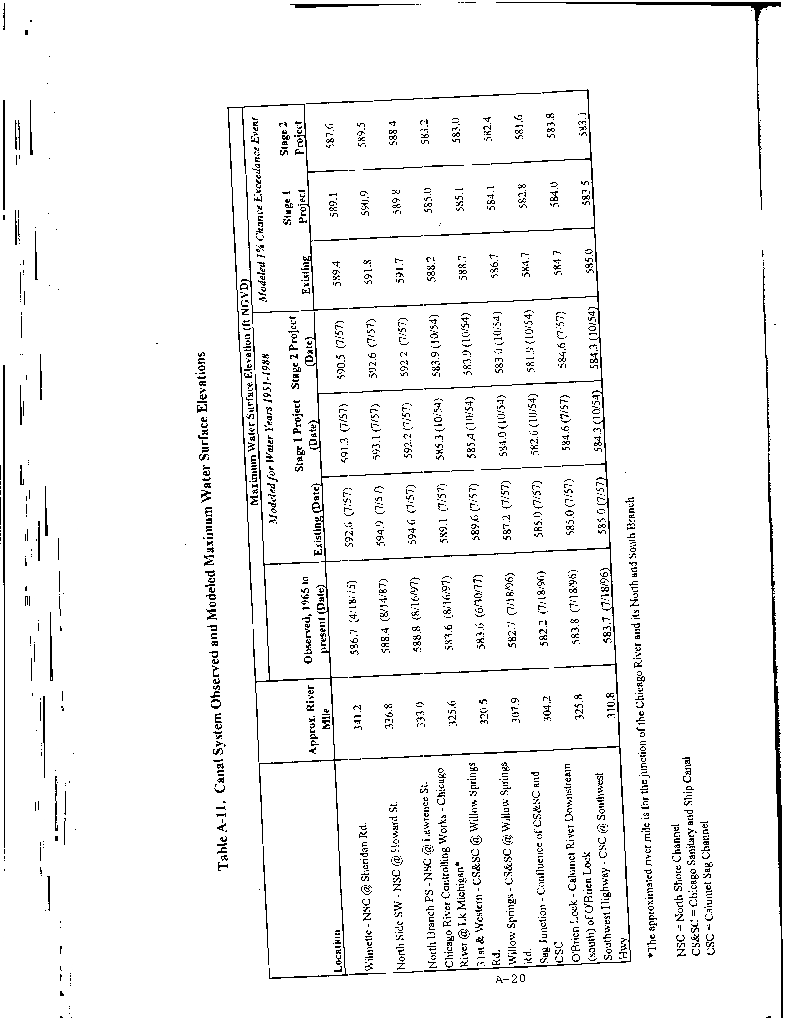
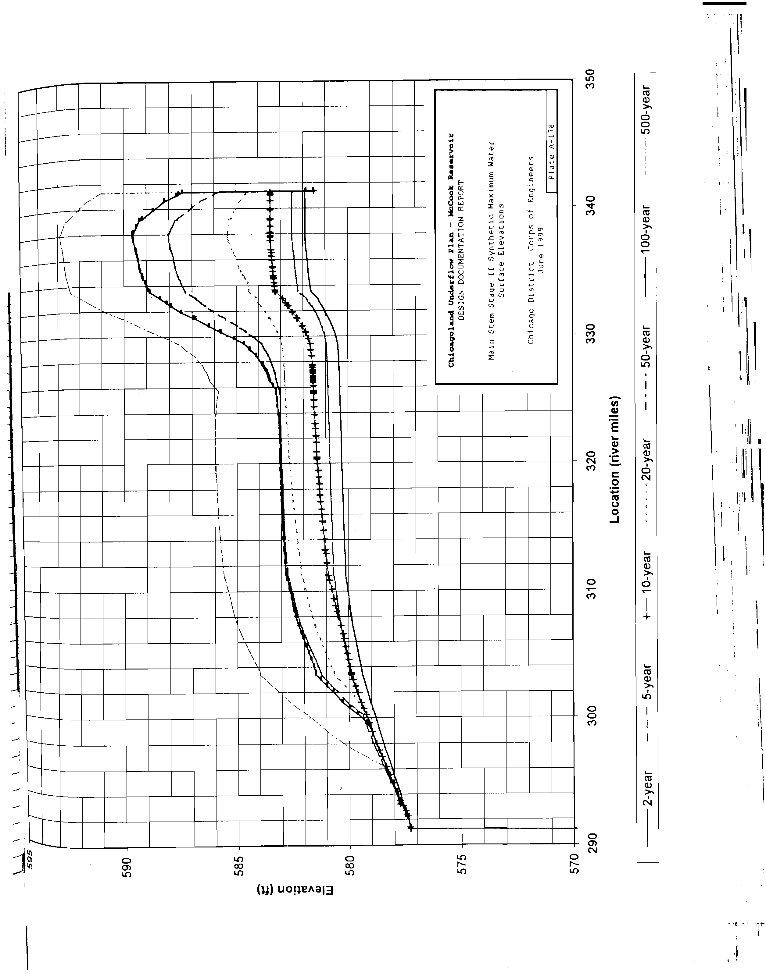
The? 100-year? flood? elevation? is? 12.30? CCD,? as? calculated? in? the? Chicago
Canal? System? Model,? UNET.? ? Appendix? A? provides? selected? pages?from? the
USACE’s? Chicago? Underflow? Plan? (CUP)? Design? Report? presenting? these
results.? ? Pre-Stage?1? (Stage?1?of? McCook?Reservoir? Construction)? values?are
used? since? the? USACE’s? current? estimate? for? completion? of? Stage? 1
construction?is?2020?or?later.
7.
Hydraulics? through? the? existing? Meter? Building? will? control? flow? splits? among
Battery?A,?B,?C,?D,?and?F?proportional?to?the?battery?volumes.
8.
Flow?splits?evenly?based?on?aeration?tank?volume?within?each?battery.
9.
Flow? splits? evenly? among? the? aerated? grit? channels? located? in? the? Grit
Building.
10.?
Return? Activated? Sludge? (RAS)? flows? were? calculated? to? be? 55%? of? total
influent?flow.
11.?
Internal? recycle? flow? for? total? nitrogen? removal? was? calculated? to?be? 150%? of
total?influent?flow?per?battery.
12.?
Baffle? walls? (for? TN? removal)? were? assumed? to? be? mounted? where? mixed
liquor?flows?from?underneath?one?baffle? wall?to? the? top? of?the?next? baffle? wall,
creating?a?“up?and?down”?flow?pattern.
13.?
The?longest?flow?path?through?each?treatment?process?was?used.
14.?
Tank? geometry? downstream? of? the? aeration? tank? effluent? weirs? (Operating
Gallery? and? Final? Settling? Tanks)? in? Battery? A? was? assumed? to? be? similar? to
that?of?existing?Battery?D.
15.?
Geometry?of?Batteries?E? and? F?were?assumed? to?be?similar? to? that? of?existing
Battery?D.
16.?
Proposed?primary?settling?tank?geometry?was?assumed?to?be?similar?to?that?of
the?existing?circular?primary?settling?tanks.
17.?
Velocity?in?Disinfection?Influent?and?Effluent?Distribution?Chamber?is?zero
18.?
Battery? E? is? to? be? pumped? via? the? proposed? low-lift? pump? station? on? the
existing?(southern)?NSWRP?site.
19.?
Battery?E?is?gravity?Fed?from?downstream?of?the?Grit?Building.
20.?
Disinfection? channel? effluent? weir? gate? is? assumed? to? be? downstream? WSE
(WSE?4)?+?0.5'
21.?
The?following?modeling?equations?were?used:
a.? Pressure?Flow?–?Hazen?Williams?Equation
b.? Open-Channel?Flow?–?Manning’s?Equation
c.? Flow?junctions?–?Pressure?Momentum?Analysis
22.?
Hydraulic?coefficients?used?in?developing?this?model?include:
a.? Hazen?W illiams?–?110?(concrete)
b.? Manning’s
i.?
Regular?channel?–?0.013
ii.?
Aerated?channel?–?0.035
3.4?
Results
Results? are? presented? below.? ? Tertiary? filters? are? excluded? from? the? hydraulic? profile.
The?hydraulic?profiles?show?the?estimated?WSEs?at?the?maximum?flow?of?450?mgd.??Flow
Electronic Filing - Received, Clerk's Office, October 20, 2008
11
that? exceeds? 450? mgd? is? diverted? into? the? TARP? system
Tabl
.
e? 2
? presents? the
headlosses? through? various? portions? of? the? plant? for? Battery? A? and? Battery? E? for
comparison.
Table?2?–?Summary?of?Headloss?through?NSWRP?(Proposed)
Process/Flow?Area
Battery?A
Battery?E
Pump?and?Blower?House?Discharge?to?Aerated
Grit?Discharge?Chamber
2.03
2.03
Aerated?Grit?Discharge?Chamber?to?PSTs
1.03
2.39
Primary?Settling?Tanks
1.83
2.44
Aeration?Basins?and?Final?Settling?Tanks
5.98
2.72
Effluent?Conduit?to?Low?Lift?Pump?Station?Wet
Well
0.67
1.96
LLPS?Discharge?to?UV?Disinfection?Effluent
Chamber
3.36
3.36
UV?Disinfection?Effluent?Chamber?to?Outfall
.66
.66
Total
15.56
15.56
Notes:??
Values?i n ? f e e t ?of?he a dloss .
Does?not?include?head?dissipated?due?to?minimum?pump?head?requirements.
Table?3
?presents?the?final?water?surface?elevations?through?the?plant?including?the?Low
Lift?Pump?Station?and?UV?Disinfection?Building.
Table?3?–?Summary?of?Proposed?WSE?including?UV?Disinfection?Facilities
Location
Combined
Battery?A
Battery?E
North?Shore?Channel?100-yr?Flood
Elevation
12.30
--
--
D/S?WSE?@??New?Surge?Chamber
12.96
--
--
U/S?WSE?@?New?Surge?Chamber
15.96
--
--
WSE?@?Disinfection?Effl?Channel
16.52
--
--
WSE?just?U/S?of?Weir?Gate
18.03
--
--
WSE?just?D/S?UV?Reactor
18.08
--
--
WSE?just?U/S?UV?Reactor
18.83
--
--
WSE?just?D/S?of?influent?gate
18.87
--
--
WSE?in?LLPS?Discharge?Channel
19.88
--
--
LLPS?Wet?Well
16.00
--
--
Final?Settling?Tank?Effluent?Chambers
--
16.67
17.96
Aeration?Tank?Effluent?Chambers
--
20.39
18.88
Aeration?Tanks
--
20.69
19.62
Primary?Tank?Effluent?Chambers
--
22.65
20.68
Grit?Building?Effluent?Chamber
25.51
--
--
U/S?of?Fine?Screens
25.76
--
--
Aerated?Grit?Tank?Influent?Chamber
26.51
--
--
Siphon?Room
27.54
--
--
Figure?5a?and?5b
?contain?hydraulic?profiles?of?the?two?critical?flow?paths?with?the?UV
disinfection?facilities?and?the?available?freeboard?at?the?locations?where?water?surface
elevations?(WSEs)?were?calculated?at?the?maximum?day?flow.
Electronic Filing - Received, Clerk's Office, October 20, 2008
CTE
303?East?Wacker?Drive,?Suite?600,?Chicago,?Illinois?60601-5276
T?312.938.0300?F?312.938.1109?www.cte.aecom.com
Electronic Filing - Received, Clerk's Office, October 20, 2008
CTE
303?East?Wacker?Drive,?Suite?600,?Chicago,?Illinois?60601-5276
T?312.938.0300?F?312.938.1109?www.cte.aecom.com
Electronic Filing - Received, Clerk's Office, October 20, 2008
14
4
LOW?LIFT?PUMP?STATION
This? section? will? present? the? proposed? arrangement? and? key? characteristics? of? the
proposed?Low?Lift?Pump?Station.
Based? on? the? above? analysis? of? hydraulics,? it? is? estimated? that? the? low? lift? pumps? will
raise? the? water? approximately? 7? feet? (including? static? and? friction? losses)? to? the? UV
disinfection? system? influent,? including? estimated? head? to? allow? flow? through? the? UV
system.? ? Should? tertiary? filtration? become? necessary? in? the? future,? these? pumps? can? be
modified?to?enable?an?increased?head?of?approximately?11?feet.
Pumps?will? be? axial?flow,?propeller? type.? ? The?pumps?will? operate?24?hours?a? day,?seven
days?per?week.??The?level?control?will?be?automatic?under?normal?conditions,?with?manual
override?possible.
4.1?
Basis?of?Design
Table?4
?provides?a?summary?of?the?basis?of?design?for?the?Low?Lift?Pump?Station.
Table?4?–?Low?Lift?Pump?Station?Basis?of?Design
Flow,?MGD
450
Pumps
Type
A x ial?Flow
Number
6?total?(N+1+1)
Pumping?Rates,?gpm/pump
78,125
Total?Dynamic?Head,?ft.
7
Motor,?hp
250
Submergence,?ft
16
Wet?Well
Length,?ft.
86
Width,?ft.
101
4.2?
Pump?Type
Several? pump? types? were? considered? for? this? high? flow? (78,125? gpm)? low? head? (7? feet
TDH)? application.? ? Pump? types? considered? included? screw? pumps,? vertical? turbine
pumps,? centrifugal? pumps,? and? axial? flow? pumps.? ? Many? pump? manufacturers? found? it
difficult? to? recommend? a? pump? that? would? operate? efficiently? for? this? application? due
primarily? to? the? low? head.? ? Screw?pumps? and? axial?flow? pumps?appear? to?have? the? best
operating?performance?for?this?condition.
Initially?the?Low?Lift?Pump?Station?will?lift?450?MGD?a?total?of?4?feet?with?a?Total?Dynamic
Head? (including? station? losses)? of? approximately? 7? feet.? ? However,? if? tertiary? filtration? is
constructed?in?the?future,?the?TDH?will?increase?to?approximately?11?feet?(flow?will?remain
the? same).? ? Screw? pumps? will? not? easily? accommodate? this? change? in? head,? without
significant? structural? modifications? to? the? pump? station.? ? However,? axial? pumps? can? be
modified? for? future? head? conditions.? ? Structural? modifications? to? the? pump? station? to
accommodate? these? changes,? if? required,? should? be? minimal.? Therefore,? axial? flow,
propeller?type?pumps?are?recommended.
Electronic Filing - Received, Clerk's Office, October 20, 2008
15
4.3?
Proposed?Operational?Description
The?pump?station? will? have?a? total? of?six?pumps,?with?four? duty?pumps,?one? standby?and
one? out? of? service? (N+1+1).? ? Four? pumps? will? be? driven? by? constant? speed? motors,? two
will?be?variable?speed?driven.??In?order?to?provide?operational?flexibility,?the?pump?station
will? be? divided? into? two? wet? wells,? each? containing? three? pumps.? ? Design? average? flow
(333? MGD)? can? be? handled? by? two? constant? speed? and? one? variable? speed? pumps,
leaving? three? pumps?on? standby.??Peak?flow?(450?MGD)? can?be?handled?by?four?pumps,
leaving? two? on? standby.? ? Typically,? at? least? one? variable? speed? pump? will? operate? at? all
times,?to?handle?fluctuations?in?flow
Tab
.
le?5
?illustrates?an?example?of?pump?operation?at
design?average?flow?and?peak?flow:
Table?5?–?Summary?of?Pump?Operation
Flow,?MGD
Pump?Drive?Type
Pump?Flow,?gpm
250
Constant?speed
78,125
Constant?speed
78,125
Variable?speed
46,875
333?(Design
Average)
Constant?speed
78,125
Constant?speed
78,125
Variable?speed
75,000
450?(Peak)
Constant?speed
78,125
Constant?speed
78,125
Constant?speed
78,125
Variable?speed
78,125
In? order? to? eliminate? vortices,? pumps? require? a? minimum? submergence? as? a? function? of
pump? suction? bell? diameter.? ? For? this? flow? condition,? a? 96-inch? suction? bell? is? required,
which? requires? a? minimum? submergence? of? 168? inches,? or? 14? feet.? ? Submergence
requirements?should?be?verified?by?the?pump?manufacturer?during?final?design.
Level?sensors?in?the? wet? well? will? relay? a? signal?to? turn? pumps?on? and? off.?? Other? control
inputs?that?need?to?be?monitored?include?discharge?pipe?pressure,?flap?gate?position,?and
motor?alarms.
4.4?
Proposed?Layout
Flow?will?enter?the?pump?station?at?the?north?end?of?the?wet?well,?where?it?will?be?directed
perpendicularly? to?the? south? through?four? 96-inch?slide?gates.? ? Pumps?are? located?at?the
south? end? of? the? pump? station.? ? Site? constraints? and? pump? station? size? appear? to? make
this?flow?pattern?necessary.
Available? area? on? the? site? is? insufficient? for? meeting? Hydraulic? Institute? (HI)? Standards
directly.? ? A? trench? type? wet? well? was? considered? in? order? to? meet? HI? standards,? but? its
depth,?in?excess?of?fifty?feet,?precluded?further?study.
A? rectangular? wet? well? is? shown? in? the? plan? and? section.? ? Design? features,? which? have
been? shown? to? be? effective? in? other? installations,? were? incorporated? in? this? design? in
order?to?meet?HI?standards.??For?example,?perforated?plates,?curtain?walls,?and?floor?and
back?wall?splitters?have?been?incorporated?into?the?conceptual?design.??(See?Appendix?B
for? a? plan? and? section? of? the? proposed? layout).? ? Sizing? and? details? of? these? types? of
features? are? normally? determined? by? physical? scale? modeling? during? detailed? design.
Electronic Filing - Received, Clerk's Office, October 20, 2008
16
Furthermore,? based? on? the? total? flow? and? flow? per? pump,? the? Hydraulic? Institute
recommends?physical?scale?modeling.
5
SUMMARY
This? technical? memorandum? has? been? developed? as? part? of? the? Preliminary? Cost
Opinion? for? Ultraviolet? (UV)? Disinfection? Facilities? Study? at? the? Metropolitan? Water
Reclamation? District? of? Greater? Chicago’s? (MWRDGC,? or? District)? North? Side? Water
Reclamation? Plant? (NSWRP)? in? Skokie,? Illinois.? ? The? study? is? advancing? the? previous
work? outlined? in? the? NSWRP? Master? Plan? and? TM1-W Q? based? on? the? comments
received? from? the? United? Stated? Environmental? Protection? Agency? (USEPA)? as? part? of
the?Use?Attainability?Analysis?(UAA)?evaluations?and?new?information?obtained?since?the
previous?work.
CTE’s? efforts? to? date? have? identified? several? issues? that? must? be? addressed? during? the
conceptual? design? of? the? disinfection? facilities.? ? These? issues? include:? ? incorporation? of
the? disinfection? facilities? into? the? NSWRP? Master? Plan? for? future? improvements,? the
timing? of? the? implementation? of? proposed? improvements? that? might? influence? the? design
of? the? disinfection? facilities,? and? existing? hydraulic? constraints? given? the? needs? of? the
proposed?future?improvements.
Through? the? work? completed? during? the? Master? Plan,? it? has? been? determined? that? the
disinfection?facilities? will? be? located? in? the?northeast?corner?of?the?existing? site? due? to? the
proximity? to? the? existing? outfall? and? effluent? conduit? as? well? as? space? needs? for
construction?of?other? required?future?facilities?(i.e.?Battery?E)?at?other?available? locations.
The? proposed? disinfection? facilities? are? assumed? to? be? constructed? after? Battery? E? is
online,?but?before?the?addition?of?tertiary?filtration.??The?anticipated?time?frame?for?startup
of? the? disinfection? facilities? is? 2014? to? 2016? for? the? purposes? of? the? Disinfection? Cost
Study.? ? This? schedule? should? be? considered? conservative? in? the? sense? that? the
implementation? schedule? may? be? longer? than? assumed? here? due? the? complexity? of? the
required? planning? and?design? efforts?for? facilities?of? this? magnitude? and? the? potential? for
delay?due?to?the?uncertainty?inherent?to?the?regulatory?process.
Using?the?hydraulic?analysis?work?completed?for? the? NSWRP? Master? Plan,?a? preliminary
evaluation? of? the? hydraulic? profile? for? the? proposed? facilities? was? completed? assuming
that? all? flow? continued? to? be? by? gravity? downstream? of? the? influent? Pump? and? Blower
House.? ? This? evaluation? shows? that? water? surface? elevation? at? peak? flow? at? the? surge
chamber? is? below? the? 100-year? flood? elevation? and? therefore,? the? plant? would? not? be
capable? of? treating? the? peak? design? flow.? ? Considering? that? this? is? a? conceptual? level
study? and? additional? losses? are? likely?to?be? identified? during? final? design,? it? is? concluded
that? additional? pumping? for? all? flows? from? the? existing? site? (Batteries? A,? B,? C,? D,? and? F)
and?from?Battery?E?is?required?in?order?to?convey?and?treat?peak?flows.
Several? alternatives? were? considered? regarding? the? layout? and? location? of? the? pumping
on? the? site.? ? The? recommended? alternative? is? to? provide? a? single? low? lift? pump? station
downstream? of? the? final? clarifiers? for? all? secondary? treatment? batteries? but? upstream? of
the?disinfection?facility.??This?arrangement?minimizes?the?number?of?times?that?the?flow?is
pumped?and?the?number?of?locations?of?the?major?pumping?equipment.??It?will?also?permit
bypassing?of?the?LLPS?and?disinfection?facility?during?winter? months? when? disinfection? is
not?required.??In?addition,?this?alternative?more?easily?allows?diversion?of?the?effluent?to?a
tertiary?filter?facility?in?the?future.
Electronic Filing - Received, Clerk's Office, October 20, 2008
17
The? hydraulic? analysis? was? refined? based? on? the? proposed? layout? of? the? facilities? to
determine? the? specific? needs? for? the? LLPS.? ? A? proposed? layout? of? the? LLPS? has? been
developed? based? on? axial?flow? pumps.? ? Axial?flow? pumps? are? recommended? due? to? the
low? head? conditions?and? the? need? to? modify?the? discharge? head? when? tertiary?filters?are
added?in?the?future.??The?primary?alternative?to?axial?flow?pumps?is?screw?pumps,?but?this
pump?type?is?not?easily?modified?after?installation?to?provide?additional?head.
The? wet? well? layout,? shown? in? Appendix? B,? is? constrained? by? the? available? space? and
does? not? meet? ideal? Hydraulic? Institute? pump? intake? standards.? ? However,? pump? intake
flow?improving?features?were? incorporated? into?the? layout?of?the? wet? well?similar? to?other
pump? stations? of? similar? size? and? application.? ? Physical? scale? modeling? during? detailed
design? is? strongly? recommended?due? to?the? size?of?the?pumps?and?to? verify?and?size?the
hydraulic?improvements.
In?conclusion,?this?review?has?confirmed?the?primary?assumptions?of?the?NSWRP?Master
Plan? in? regards? to? the? need? for? a? low? lift? pump? station,? location? of? the? facilities,? and
arrangement? of? the? facilities? to? accommodate? future? facilities.? ? The? Disinfection? Cost
Study? will? proceed? based? on? the? assumption? and? the? additional? details? provided? in? this
report.
Electronic Filing - Received, Clerk's Office, October 20, 2008
APPENDIX?A
Selected?Pages?from?USACE?CUP?DDR
Electronic Filing - Received, Clerk's Office, October 20, 2008
Electronic Filing - Received, Clerk's Office, October 20, 2008
Electronic Filing - Received, Clerk's Office, October 20, 2008
Electronic Filing - Received, Clerk's Office, October 20, 2008
Electronic Filing - Received, Clerk's Office, October 20, 2008
Electronic Filing - Received, Clerk's Office, October 20, 2008
Electronic Filing - Received, Clerk's Office, October 20, 2008
APPENDIX?B
LLPS?Proposed?Layout
Electronic Filing - Received, Clerk's Office, October 20, 2008
\\Uschg1fp207\p60026610\P60026610\Contracts\SHEETS\P-301.dwg,?9/26/2007?10:40:18?AM,?DWF6?ePlot.pc3
N
A
S-302
A
S-302
PRELIMINARY
Electronic Filing - Received, Clerk's Office, October 20, 2008
\\Uschg1fp207\p60026610\P60026610\Contracts\SHEETS\P-302.dwg,?9/26/2007?10:40:23?AM,?DWF6?ePlot.pc3
N
A
S-302
A
S-302
PRELIMINARY
Electronic Filing - Received, Clerk's Office, October 20, 2008
\\Uschg1fp207\p60026610\P60026610\Contracts\SHEETS\P-303.dwg,?9/26/2007?10:40:27?AM,?DWF6?ePlot.pc3
N
PRELIMINARY
Electronic Filing - Received, Clerk's Office, October 20, 2008
APPENDIX?B
UV?TECHNOLOGY?TECHNICAL?MEMORANDUM
Electronic Filing - Received, Clerk's Office, October 20, 2008
DISINFECTION?COST?STUDY
ULTRAVIOLET?DISINFECTION?TECHNOLOGY
EVALUATION
FOR
METROPOLITAN?WATER?RECLAMATION
DISTRICT?OF?GREATER?CHICAGO
NORTH?SIDE?WATER?RECLAMATION?PLANT
TECHNICAL?MEMORANDUM
OCTOBER?23,?2007
Prepared?By
303?EAST?WACKER?DRIVE,?SUITE?600
CHICAGO,?ILLINOIS?60601
MWRDGC?Project?No.?07-026-2P
CTE?Project?No.?60026610
Electronic Filing - Received, Clerk's Office, October 20, 2008
i
TABLE?OF?CONTENTS
INTRODUCTION........................................................................................................................ 1
Background .................................................................................................................... 1
Objective ........................................................................................................................ 1
AVAILABLE?UV?DISINFECTION?TECHNOLOGIES ................................................................... 2
Low?Pressure?–?Low?Intensity?(LP-LI) ............................................................................. 2
Low?Pressure?–?High?Intensity?(LP-HI) ............................................................................ 3
Medium?Pressure?–?High?Intensity?(MP-HI) ..................................................................... 3
LITERATURE?REVIEW?OF?SELECTED?MP-HI?UV?TECHNOLOGY.......................................... 4
Typical?MP-HI?System?Configuration .............................................................................. 4
Influent?Characteristics ................................................................................................... 4
Reactor?Configuration?and?Hydraulics............................................................................. 5
Lamps?and?UV?Intensity?Control ..................................................................................... 5
Lamp?Fouling?and?Cleaning ............................................................................................ 5
Process?Control .............................................................................................................. 6
Safety ............................................................................................................................. 6
REVIEW?OF?TECHNOLOGIES?FROM?MANUFACTURERS...................................................... 7
Trojan?Technologies?–?Trojan?UV4000™ Plus ................................................................. 7
Aquionics?–?InLine50,000+.............................................................................................. 7
Calgon?Carbon?–?C
3
500™ .............................................................................................. 8
Severn?Trent?Services?(STS)/Quay?–?MicroDynamics™ ................................................. 8
REFERENCE?INFORMATION?FROM?OTHER?OPERATING?FACILITIES ............................... 10
Case?Study:??Clayton?Water?Reclamation?Center?(WRC),?Atlanta,?GA.......................... 10
Telephone?Survey?of?Experience?at?Other?Facilities...................................................... 11
DISTRICT?UV?EQUIPMENT?TRIALS?PROJECT?AND?SUPPORTING?WATER?QUALITY
INFORMATION ........................................................................................................................ 14
Need?for?Pilot?Testing ................................................................................................... 14
BASIS?OF?DESIGN?OF?UV?SYSTEM?FOR?NORTH?SIDE?WRP .............................................. 16
REFERENCES......................................................................................................................... 17
Electronic Filing - Received, Clerk's Office, October 20, 2008
ii
LIST?OF?TABLES
1
Typical?UV?Technology?Categories?(Bazzazieh,?2005).................................................... 3
2
Summary?of?Manufacturer-recommended?UV?Technologies?for?NSWRP........................ 9
3
Basis?of?Design?–?Clayton?WRC ................................................................................... 10
4
Operational?Data?–?Clayton?WRC?(April?to?September,?2001) ....................................... 10
5
Summary? of? Telephone? Interviews? of? Utilities? Using? MP-HI? UV? Disinfection
Systems........................................................................................................................ 13
6
Summary?of?2006/2007?Water?Quality?Testing.............................................................. 14
7
Design?Parameters?for?UV?Disinfection?Unit?at?NSWRP................................................ 16
LIST?OF?FIGURES
1
Categories?of?Currently?Available?UV?Disinfection?Systems?(Hunter,?et?al.,?2006b)......... 2
2
UV4000+?System?(Courtesy?of?Trojan?Technologies) ..................................................... 7
3
InLine50,000+?System?(Courtesy?of?Aquionics) .............................................................. 8
4
TAK25?System?(Courtesy?of?ITT/Wedeco) ...................................................................... 8
5
MicroDynamics?System?(Courtesy?of?STS/Quay)............................................................ 9
LIST?OF?APPENDICES
Appendix
Content
A
2006?UV?TRIAL?WATER?QUALITY?DATA?NSWRP,?CWRP,?AND
HPWRP
Electronic Filing - Received, Clerk's Office, October 20, 2008
1
INTRODUCTION
Background
This? technical? memorandum? has? been? developed? as? part? of? the? Preliminary? Cost
Opinion? for? Ultraviolet? (UV)? Disinfection? Facilities? Study? at? the? Metropolitan? Water
Reclamation? District? of? Greater? Chicago’s? (MWRDGC,? or? District)? North? Side? Water
Reclamation? Plant? (NSWRP)? in? Skokie,? Illinois.? This? memorandum? continues? the? work
began? in? TM1-WQ,? which? was? developed? previously? as? part? of? the? comprehensive
Infrastructure? and? Process? Needs? Feasibility? Study? (Feasibility? Study)? for? the? NSWRP
and?a?Water?Quality?(WQ)?Strategy?for?affected?Chicago?Area?Waterways.
The?TM1-WQ?documented?the?results?of?a?CTE?study?of?effluent?disinfection?alternatives
for?the? District’s? North? Side,? Calumet?and? Stickney?WRPs.? In? that? study,? a? task?force? of
national? experts? (referred? to? as? the? Blue? Ribbon? Panel)? reviewed? different? disinfection
technologies? and? their? range? of? pathogen? destruction? efficiency,? disinfection? byproducts
and? impacts? upon? aquatic? life? and? human? health.? ? Their? investigation? also? included? an
examination? of? the? environmental? and? human? health? impacts? of? the? energy? required? for
the?operation?of? the?facility?and?for? the?processing? and? production? of?process? chemicals.
Based?on?economic?and?non-economic?evaluation?of?alternatives,?ozone?disinfection?and
UV? disinfection? were? selected? and? preliminary? basis? of? design? and? cost? estimates? were
developed.? The? UV? disinfection? system? using? medium? pressure? high? intensity? lamps
provided?by?Trojan?Technologies,?Inc.?was?used?as?a?basis?of?design?and?cost?estimates
for?the?UV?system.
Objective
Per?the?District’s?request,?further?evaluation?of?the?UV?disinfection?technology?is?required.
This? additional? evaluation? is? based? on? the? TM-1WQ,? the? comments? received? from? the
EPA? as? part? of? the? UAA? evaluations,? and? new? information? obtained? since? the? previous
work.?The?primary?objectives?of? the? evaluation? presented? in?this?technical?memorandum
are:
•
?
To? describe? the? current? UV? technologies? being? used? to? disinfect? wastewater
treatment?plant? effluent?and? to?find? if? changes? have? occurred? in? the? selected? UV
technology
•
?
To? get? updated? recommendations? and? costs? from? different? vendors? for? the
selected?technology
•
?
To?incorporate?information?available?from?literature
•
?
To?provide?references?of?experience?in?UV?disinfection?at?other?facilities
In? the? following? discussion,? the? results? of? this? evaluation? are? given.? The? sections? that
follow? summarize? the? currently? available? UV? technologies? for? disinfection? and? the
experience? of? using? such? systems? in? WWTPs,? and? provide? an? updated? basis? of? design
for?the?selected?UV?disinfection?system?at?the?NSWRP.
Electronic Filing - Received, Clerk's Office, October 20, 2008
2
AVAILABLE?UV?DISINFECTION?TECHNOLOGIES
In? the? past? 20? years,? UV? disinfection? has? gained? popularity? as? it? is? becoming? more
feasible? to? implement? due? its? advantages? over? alternate? disinfection? methods? (i.e.
chlorination/dechlorination,? ozonation,? etc)? as? noted? in? TM-1WQ.? The? UV? disinfection
systems? have? also? become? more? sophisticated,? reliable,? and? cost-effective.? The
currently? available?technologies?of?UV?disinfection? used? are? shown? in? Figure?1? (common
configurations?for?municipal?wastewater?applications?are?shown?bold).
Figure?1?–?Categories?of?Currently?Available?UV?Disinfection?Systems?(Hunter,?et
al.,?2006b)
To? maximize? the? efficiency? of? the? system,? the? light? source? must? emit? at? the? wavelength
range? where? DNA? and? RNA? molecules? in? the? microorganisms? exhibit? a? maximum
absorbance? of? UV? light? (254? nM).? Hence,? the? most? important?element? of? UV? systems? is
the? light? source? or? lamp.? Based? on? the? source? of? UV,? these? disinfection? systems? are
categorized? into? three? categories.? The? important? characteristics? of? these? categories? are
given? in? Table? 1.? Here,? “Pressure”? refers? to? the? pressure? of? gasses? inside? the? lamp.
“Intensity”?refers?to?the?energy?output.
Low?Pressure?–?Low?Intensity?(LP-LI)
Available? for? more? than? 20? years,? low-pressure? lamps? are? arranged? in? horizontal? or
vertical? configurations? submerged? in? relatively? shallow? flow? channels.? Enclosed? and
Teflon-tube?systems?are?also?available.?Lamp?control?is?limited?to?"on"?and?"off."?These
Current?UV?Disinfection?Systems
Low?Pressure?Lamps
Medium?Pressure?Lamps
Pulsed?Power
Xenon?
Excimer
Open?Channel
Horizontal
Lamps?parallel?to?flow
Closed?Channel
Horizontal
Lamps
perpendicular?to
flow
Closed
Chamber
Low?Intensity
Conventional
High?Intensity
Open
Channel
Closed
Chamber
Teflon
Tubes
Horizontal
Lamps?parallel?to?flow
Vertical
U-shaped
Quadritubes
Fatl
Lamps
Highout
Ballast
Horizontal Vertical
Electronic Filing - Received, Clerk's Office, October 20, 2008
3
lamps?are?the?most?energy?efficient?lamps?used?for?UV?disinfection?because?85%?of?their
Table?1?–?Typical?UV?Technology?Categories?(Bazzazieh,?2005)
UV?System
Low?Pressure,
Low?Intensity
Low?Pressure,
High?Intensity
Medium?Pressure,
High?Intensity
Lamp?mercury
pressure,?torr
10
-3
?to?10
-2
10
-3
?to?10
-2
10
2
?to?10
3
Lamp?operating
temperature,
degrees?C
40
90?to?250
600-900
Typical?power?use
per?lamp,?watts
70?to?85
170?to?1,600
2,000?to?5,000
Cleaning
Manual
Automatic?wipers?? Automatic?wipers
total? emissions? are? near? the? peak? for? germicidal? effectiveness? (NYSERDA,? 2004).? The
estimated? lifetime? of? the? lamp? is? approximately?13,000? hours.?They?are? typically?used? at
facilities?where?the?design?flow?is?less?than?5?MGD?(Hunter,?et?al.,?2006b).?Because?more
lamps? are? needed? as? flow? increases,? the? related? maintenance? costs? at? large? facilities
may?be?higher?than?those?for?other?UV?systems.
Low?Pressure?–?High?Intensity?(LP-HI)
Introduced?within?the?last?several?years,?early?installations?of?low-pressure,?high-intensity
lamp? systems? were? deliberately? overdesigned,? involving? multiple? banks? of? lamps? and
cumbersome? hydraulic? diversion? controls? designed? to? turn? lamp? banks? on? and? off? as
operating? conditions? dictated.? When? these? systems? were? on,? all? lamps? in? the? bank? or
channel? operated? at?full? intensity.? Newer? improvements?allow?the? lamp's? wattage? output
to? be? varied? to? optimize? dose? delivery.? These? systems? also? include? an? automatic
cleaning? system.? These? lamps? have? an? average? lifetime? of? about? 8,000? hours,? with
gradually?falling? lamp? intensities? (NYSERDA,?2004).?These? systems?use? about?one-third
the? lamps? of? low-pressure? systems? but? also? about? three? times? more? than? medium-
pressure?systems?(Hunter,?et?al.,?2006b).
Medium?Pressure?–?High?Intensity?(MP-HI)
Medium-pressure? lamps? became? available? in? open-channel? and? closed-pipe
configurations? during? the? last? decade.? They? use? more? power? and? generate? higher? head
losses?than?the?low-pressure?systems?(Bazzazieh,?2005).??An?automatic?cleaning?system
that? periodically? removes? the? solids? that? coat? the? quartz? sleeves? is? also? required.? ? The
lamps? have? an? average? lifetime? of? about? 8,000? hours? with? intensity? gradually? declining
over? time? (NYSERDA,? 2004).? Because? they? have? higher? UV? output,? medium-pressure
systems? use? about? one-tenth? the? number? of? lamps? that?a? low-pressure? system? requires
(Hunter,? et? al.,? 2006b).? Medium? pressure? UV? lamps? are? mostly? recommended? for? larger
wastewater? treatment? plants? where? the? provisions? for? head? requirements? could? be
incorporated? in? the? design,? and? where? a? smaller? footprint? and? lower? maintenance? is
needed.
Thus,? the? technologies? are? distinguished? by? the? germicidal? intensity? given? off? by? each
lamp? type,?which? correlates?to? the? number? of? lamps?required?and? the? overall? UV? system
size?in?order?to?provide?a?specified?dose?of?energy?to?the?target?media?(pathogens?within
Electronic Filing - Received, Clerk's Office, October 20, 2008
4
the?plant?effluent).??The?lamp?type?selected?is?determined?on?a?site-specific?basis.?For?the
NSWRP,? the? District? has? selected? the? MP-HI? system? of? UV? disinfection? based? on? their
interest? in? minimizing? the? total? number? of? lamps? required? and? the? recommendations? of
the? Blue? Ribbon? Panel? during? the? NSWRP? Master? Plan.? ? Further? investigation? of? this
technology?is?discussed?in?the?following?sections.
LITERATURE?REVIEW?OF?SELECTED?MP-HI?UV?TECHNOLOGY
Information? on? the? latest? developments? and? experience? in? using? the? MP-HI? UV
disinfection? system? was? researched? in? literature? including? technical? proceedings? from
Water? Environment? Federation? (WEF),? Water? Environment? Research? Foundation
(WERF),?proceedings?from?the?latest?Disinfection?conference?series?undertaken?by?WEF,
American? Water? Works? Association? (AWWA),? and? International? Water? Association
(IW A).? In? the? following? discussion,? a? description? of? the? latest? MP-HI? technology? is
provided.? This? section? also? summarizes? the? experiences? of? some? of? the? wastewater
treatment?facilities?that?have?successfully?implemented?UV?disinfection.
Typical?MP-HI?System?Configuration
The?MP-HI?system?involves?sending?the?secondary?or?tertiary?effluent?through?a?confined
space? containing? banks? of? MP-HI? UV? lamps.? A? typical? MP-HI? UV? system? currently
consists?of? a? power? supply,? an? electrical? system,?a? reactor,? MP-HI? lamps,? a? mechanical
and/or? chemical? cleaning? system,? and? a? control? system.? The? MP-HI? UV? lamps? are
enclosed? in? individual? quartz? sleeves? for? protection? against? dirt? and? breakage.? Reactor
chambers? (open? or? enclosed? channels)? hold? the? lamps? in? either? a? horizontal? or? vertical
configuration.? In? an? open? channel? system,? effluent? weirs? or? automatic? level? control
devices? are? used? to? keep? the? lamps? submerged? under? the? effluent? water? to?ensure? that
the? lamps? to? not? overheat,? which? can? reduce? lamp? life? or? result? in? lamp? burnout.? The
whole? UV? system? is? also? sometimes?enclosed? in? a? building? to? protect? it? from? the? natural
elements.
The? MP-HI? UV? systems? can? be? divided? into? several? key? components? for? design? and
troubleshooting? purposes? including? the? quality? of? the? influent? to? the? UV? system,
hydraulics? and? headloss,? the? level? of? disinfection? that? must? be? attained? for? compliance
with? the? regulatory? requirements,? the? reactor? configuration,? the? quartz? sleeves,? frames,
the? cleaning? mechanisms,?the? lamps,? ballasts? or?transformers,? wiring,? and? the?electrical
control?system.?Brief?descriptions?of?the?important?process,?mechanical,?and?some?of?the
electrical?components?are?discussed?in?this?section.
Influent?Characteristics
The? water? quality? characteristics? that? affect? UV? transmittance? include? iron,? hardness,
suspended? solids,?humic? materials?and? organic? dyes? (NYSERDA,?2004).? Dissolved? iron
can?absorb?UV?light?and?precipitate?on?the?UV?system?quartz?tubes.?Hardness?affects?the
solubility?of? metals?that?absorb? UV? light?and?can?precipitate? carbonates?on? quartz?tubes.
Organic? humic? acids? and? dyes? also? absorb? UV? light.? Depending? on? the? disinfection
system? used,? the? UV? transmittance? needs? to? be? above? a? certain? level.? ? The? generally
accepted?minimum?transmittance?is?65%.??However,?some?commercially?available?MP-HI
systems?claim?to?disinfect?wastewater?with?UV?transmittance?as?low?as?15-percent.
Electronic Filing - Received, Clerk's Office, October 20, 2008
5
Reactor?Configuration?and?Hydraulics
An? open? channel?or? closed? conduit? is? used? as?a? reactor.? One? or? more? than? one? reactor
may? be? necessary? to? disinfect? the? total? amount? of? effluent.? UV? disinfection? systems
employ? a? variety? of? physical? configurations? but? the? most? common? ones? have? lamps
arranged?in?linear?configuration?to?increase?intensity?along?the?linear?axis?by?avoiding?UV
emission? losses? due? to? self? absorption,? reflection? or? refraction? that? can? occur? if? a? UV
lamp?were?twisted?into?loops?or?spirals.
The? hydraulic? characteristics? of? a? reactor? can? strongly? influence? disinfection
effectiveness.?The?optimum?hydraulic?scenario?for?UV?disinfection?involves?turbulent?flow
with? mixing? while? minimizing? head? loss.? To? maximize? effectiveness,? UV? reactors? are
preferred? to? operate? at? a? Reynolds? Number? of? greater? than? 5,000? (NYSERDA,? 2004).
Reactor?design,?including?inlet?and?outlet?flow?distribution,?determines?how?close?the?unit
operates?to?a? plug?flow.?Inlet? conditions?are?designed? to?distribute? the? flow?and? equalize
velocities.? UV? system? outlets? are? designed? to? control? the? water? level? at? a? constant? level
with?little?fluctuation?within?the?UV?disinfection?reactor.
Lamps?and?UV?Intensity?Control
The? MP-HI? lamps? contain? mercury? vapor? and? argon? gas? that? produce? polychromatic
radiation,? which? is? concentrated? at? select? peaks? throughout? the? germicidal? wavelength
region.?Most?commercially?available? MP-HI? lamps?look? similar? to?a?fluorescent?tube? light
bulb,? but? they? are? made? of? quartz? glass? because? quartz? has? the? ability? to? transmit? UV
light.
The? intensity? of? the? lamp? is? unstable?for? the? first? 100? hours? of? operation? and? decreases
more? rapidly? during? that? period.? Hence? the? 100%? intensity? of? the? lamp? is? usually
measured? after? this? 100-hour? time? period.? These? lamps? have? a? germicidal? output? of
about? 16? W/cm,? which? is? about? 80? times? higher? than? LP-LI? lamps? (NYSERDA,? 2004).
Electronic? ballasts? for? each? lamp? are? used? to? control? the? power? to? the? lamp.? If? the? UV
dose? is? to? be? reduced,? variable? output? electronic? ballast? can? regulate? the? power? to? the
lamp? from? 100%? to? 30%.? Entire? banks? can? also? be? turned? off? if? there? is? no? flow.? This
allows? dose-pacing? based? on? the? secondary? or? tertiary? effluent? flow? and? quality,? which
helps?save?power?and?lamp?life.
Lamp?Fouling?and?Cleaning
The? MP-HI? lamps? operate? at? a? temperature? range? of? 600? to? 900? degree? C.? The? warm
temperatures? produced? by? UV? lamps? promote? the? precipitation? of? an? inorganic,
amorphous?film? (scale)? on? the? surface?of? the?quartz?sleeves?when? the? lamps?are? placed
directly? within? the? wastewater? stream.? Iron? is? the? most? abundant? metal? in? these? scales
along? with? other? mineral? salts? and? oil,? grease,? suspended? solids? deposits,? and? biofilms
(NYSERDA,?2004).?If?no?tertiary?treatment?is?provided,?physical?debris?may?contribute?to
fouling?as?well.
Lamp? fouling? significantly? reduces? the? effectiveness? of? UV? disinfection? by? blocking? the
UV? rays.? The? MP-HI? UV? disinfection? systems? must? be? cleaned? on? a? regular? basis.
Researchers? have? found? that? the? lamp? fouling? increases? linearly? with? the? time? elapsed
after? last? cleaning,? but? the? dependency? of? the? cleaning? frequency? on? the? quality? of
Electronic Filing - Received, Clerk's Office, October 20, 2008
6
effluent? is? not? well? predicted? (NYSERDA,? 2004).? So,? pilot? testing? is? usually? done? to
determine?cleaning?frequency.?Most?of?the?commercially?available?MP-HI?UV?disinfection
systems?require? mechanical?as?well?as?chemical?cleaning.?The?latest?technology?uses?a
system?of?mechanical?wipers?and?sleeves?containing?cleaning?chemicals?surrounding?the
lamp.? The? cleaning? solution? usually? contains? some? acidic? solution? that? prevents? fouling
(Darby? et? al.,? 1995).? This? cleaning? system? can? be? programmed? to? clean? at? a? set
frequency? without?the? need?for? disrupting? the?disinfection? process.?The? cleaning? solution
needs? to? be? replaced? periodically? depending? on? the? type? of? solution? used? and
characteristics?of?the?site?specific?effluent?water?quality.
Process?Control
The? need? to? pace? the? dose? in? the? MP-HI? UV? disinfection? system? is? important? because
too? much? dosing? wastes? electricity? and? too? little? dosing? would? not? meet? the? disinfection
regulatory? requirements? and? goals.? Several? process? control? options? are? available? to
control? the? dosing.? Although? manual? control? of? the? dosing? is? possible,? an? automated
process? control? facilitates? online? pacing? of? the? dose? and? also? allows? it? to? be? interfaced
with? the? plant’s? overall? supervisory? control? and? data? acquisition? (SCADA)? system.? The
flow,? lamp? output,? and? water? conditions? are? measured? in? pacing? of? the? dose,? and? an
algorithm? is? developed? based? on? long-term? measurements? to? predict? necessary? system
adjustments,?maintenance,?and?component?replacements.
Programmable? logic? control? (PLC)? technology? is? the? latest? available? process? control
technology? for? dose? pacing? in? the? MP-HI? UV? disinfection? system? (Hunter? et? al,? 2006b).
The?PLC?interacts? with?the? ballasts,?sensors,?and? online? monitoring? technology?for? each
disinfection? unit.? The? PLC? then? interacts? with? the? plant’s? overall? control? system? to? allow
remote? monitoring? and? adjustment? of? the? system.? The? PLC? is? usually? supplied? by? the
manufacturer?of?the?unit.
Safety
The?UV?disinfection?systems?are?one?of?the?safest?technologies?available?for?disinfection.
The? high? voltage? power? supplies?for? the? MP-HI? UV? disinfection? system? may? pose? some
issue? as? the? lamps? are? submerged? in? the? water? most? of? the? time,? but? compliance? with
normal? electrical? safety? codes? should? mitigate? the? hazardous? conditions.? Submerging? a
lamp? in? water,? even? if? it? is? just? a? few? inches? below? the? surface,? will? greatly? reduce? the
intensity?(NYSERDA,?2004).?Thus,?the?MP-HI?UV?reactors?should?be?designed?to?ensure
constant?water?levels?to?minimize?the?risk?of?UV?exposure.
Sudden? or? prolonged? exposure? to? ultraviolet? (UV)? light? can? result? in? eye? injury,? skin
burns,? premature? skin? aging,? or? skin? cancer.? Individuals? who? work? with? UV? disinfection
systems? –? or? in? any? area? where? UV? light? is? used? -? are? at? risk? of? UV? exposure? if? the
appropriate?protective? equipment? is? not? used.? The? UV? radiation? should? be? confined? to? a
restricted?area,?and?an?interlocked?access?system?should?be?in?place?so?that?the?UV?light
is? shut? off? when? the? protective? enclosure? is? opened? (Prentiss,? 2004).? A? UV? safety
program? for? operators? is? usually? undertaken? to? make? them? aware? of? the? effects? of? UV
exposure.
Electronic Filing - Received, Clerk's Office, October 20, 2008
7
REVIEW?OF?AVAILABLE?TECHNOLOGIES?FROM?MANUFACTURERS
As? discussed? previously,? the? Blue? Ribbon? Panel? recommended? medium? pressure,? high
intensity?technology?based?on?the?size?of?the?proposed?facilities?and?the?District’s?interest
in? minimizing? the? total? number? of? bulbs.? ? Two? commercially? available? medium? pressure,
high? intensity? systems? are? available? for? the? municipal? wastewater? market.? ? For
comparison,? low? pressure,? high? intensity? system? manufacturers? were? also? contacted.? ? A
review? of? the? information? available? from? the? UV? technology? manufacturers? has? been
summarized?in?Table?2?and?discussed?below.
Trojan?Technologies?–?Trojan?UV4000™Plus
Trojan? Technologies? recommends? their? Trojan? UV4000™ Plus? model? for? disinfection? of
the? effluent? at? the? North? Side? WRP.? The? system? is? especially? designed? for? large? scale
applications?of?10? MGD? or? more,?and?uses?MP-HI? lamps?horizontal?and? parallel?with?the
flow? incorporating? an? automatic? chemical/mechanical? cleaning? system.? Trojan? claims
that?this?system?is?capable?of?treating?wastewater?effluents?with?UV?transmittance?as?low
as? 15-percent? when? appropriately? sized.? It? has? a? PLC-based? system? to? monitor? and
control?all?UV?functions,?and?has?automated?dose?delivery?based?on?lamp?age,?and?other
water? parameters? such? as? flow? rate,? UV? transmittance,? and? turbidity.? The? system? has
high?efficiency?ballasts?that?can?vary?output?from?30%?to?100%?per?bank?to?match?the?UV
dose? with? effluent? quality? and? flow? rate.? Trojan? claims? to? have? over? 375? installations? of
this?system?worldwide.
Figure?2?–?UV4000+?System
(Courtesy?of?Trojan?Technologies)
Aquionics?–?InLine50,000+
Aquionics? has? recommended? their? InLine50,000+? system? for? disinfection? of? the? effluent
at?the?North?Side?W RP.?The?system?uses?horizontal?high?output?medium?pressure?lamps
aligned?perpendicular?to?the?flow?in?a?closed?conduit?reactor,?which?enables?treatment?of
high?flows? without?bypass.?The? manufacturer? claims?the?compact?design?achieves?a? low
pressure?drop?even?for?gravity?fed?flows,?although?reported?headloss?is?approximately?5-
6?times?that?of?an?open?channel?system.?It?comes?with?advanced?“fail-safe”?UV?monitors
with?all?functions?controlled?by?microprocessors.
Electronic Filing - Received, Clerk's Office, October 20, 2008
8
Figure?3?–?InLine50,000+?System
(Courtesy?of?Aquionics)
Calgon?Carbon?–?C
3
500™
The?C
3
500™ ? wastewater? disinfection? system? recommended?by?Calgon? Carbon?employs
low? pressure,? high? intensity? UV? lamp? technology? with? electronic? ballasts? to? effectively
disinfect? wastewater? plant? effluent.? The? modular? design? can? be? quickly? installed? in? an
open? channel?parallel? to? the? flow? of? wastewater.? The?
3
SerCies™ ? is? designed? for? simple
operation?and?trouble-free? maintenance.? It?has?a?control?system? that?allows?dose?or?flow
pacing.? The? system? has? only? automatic? mechanical? cleaning? and? does? not? utilize? any
automatic? chemical? cleaning.? Other? manufacturers? that? supply? this? type? of? system
include?ITT/Wedeco,?and?Infilco-Degremont/Ozonia.
Figure?4?–?TAK25?System
(Courtesy?of?ITT/Wedeco)
Severn?Trent?Services?(STS)/Quay?–?MicroDynamics™
STS/Quay? has? recommended? their? MicroDynamics™ ? system? for? disinfection? of? the? final
effluent?at?the?North?Side?WRP.?Their?microwave?ballast?technology?uses?microwaves?to
energize? low-pressure,? high-output? bulbs? for? wastewater? disinfection.? The? bulbs? light
instantly? and? lamps? can? be? switched? on? and? off? to? match? the? flow.? According? to? the
manufacturer,? the? main?advantage? of?the? system? is? better? control?of?power? to? the? lamps,
which? significantly? increases? the? lamp? life.? The? system? is? based? on? a? relatively? new
Electronic Filing - Received, Clerk's Office, October 20, 2008
9
concept? and? no? information? is? available? on? its? application? and? experience? at? large
wastewater?treatment?facilities.
Figure?5?–?MicroDynamics?System
(Courtesy?of?STS/Quay)
Table?2.?Summary?of?Manufacturer-recommended?UV?Technologies?for?NSWRP
Troanj
Technologies
Aquionics
Calgon?Carbon?
STS/Quay
Recommended
model
UV4000™Plus
InLine50000+
C
3
500™
MicroDynamics™
Lamp?type
MP-HI
MP-HI
LP-Ham
?I algam
LP-HI?energized
by?microwaves
Channel?dimensions
LxWxD
40’6”
?x?8’10”?x
14’4”
N/A
38’6”
?x?7’2.25”?x
6’4”
N/A
Channels
5?(4?+?1?for
redundancy)
18
15
N/A
Reactors/channel
1
1
1
N/A
Banks/reactor
2
1
2
N/A
Modules/bank
7
1
15?racks/bank
N/A
Lamps/module
24
32
8?lamps/rack
N/A
Total?lamps
1680
576
3600
N/A
Lamp?life,?hours
5,000
8,000
12,000
27,000
Lamp?configuration?
Horizontal,
parallel?to?flow
Horizontal,
perpendicular
to?flow
Horizontal,
parallel?to?flow
N/A
Headloss?through
Reactor
9”
56”
N/A
N/A
Cleaning?system
Automatic
mechanical?and
chemical
Automatic
mechanical
and?chemical
Automatic
mechanical,?non-
chemical
N/A
Price
(excluding?taxes)
$?7,986,000
$?5,221,000?
$?7,455,000
N/A
N/A ? –? N ot?available
Electronic Filing - Received, Clerk's Office, October 20, 2008
10
REFERENCE?INFORMATION?FROM?OTHER?OPERATING?FACILITIES
Case?Study:??Clayton?Water?Reclamation?Center?(WRC),?Atlanta,?GA
Source:?Goodman?and?Mills,?2002
The? Clayton? WRC? is? a? biological? nutrient? removal? plant? serving? portions? of? Fulton,
DeKalb,? and? Gwinnett? counties? and? much? of? the? City? of? Atlanta,? Georgia.? The? plant
discharges? into? the? Chattahoochee? River.? It? has?a? maximum? monthly?flow? of? 122? MGD,
with?a?permit?limit?of?30?mg/L?of?monthly?average?TSS?in?the?final?effluent.?The?maximum
allowable? Fecal? Coliform? in? the? final? effluent? is? 200? counts/100? mL? monthly? maximum
average?and?400?counts/100?mL?weekly?maximum?average.
The?plant?uses?an?open?channel,?gravity-flow?MP-HI?UV?disinfection?system?consisting?of
medium-pressure?vapor?UV?lamps,?oriented?horizontally?and?parallel?to?flow,?arranged?in
modules,?and?installed?inside?enclosed?reactors?in?open?channels.?The?basis?of?design?of
the? UV? system? is? given? in? Table? 3.? At? this? facility,? flow? from? the? filters? initially? enters? the
influent? channel? of? the? disinfection? structure,? then? flows? over? a? weir? into? a? common
influent? channel,? and? finally? flows? through? four? individual? channels.? Each? of? these
channels? is? equipped? with?a? UV? lamp? system.? In? order? for? the? UV? lamp? system? to? work
properly,?a? specified? level?of?liquid? must? be? maintained? in? the? channel?to? ensure? that?the
lamps? are? always? submerged? when? in? operation.? To? maintain? the? desired? liquid? level? in
each? channel,? downstream? weirs? are? used? prior? to? the? flow?entering? the? clearwell.? Plant
reuse?pumps?are?located?downstream?of?the?UV?system.
Table?3.?Basis?of?Design?–?Clayton?WRC
Number?of?channels
4?operational/1?future
Number?of?banks/channel
2
Number?of?modules/bank
9
Number?of?lamps/module
10
Total?number?of?lamps
720
UV?dose,?mJ/cm
2
24
Before?the?design,?installation?and?operation?of?the?UV?system,?a?collimated-beam?dose-
response? testing? was? done? to?estimate? the? sensitivity? of? the? in-fecsial?tucoliform? to? UV.
Once?the?dose?was?determined?using?the?pilot?tests,?the?system?was?installed?and?came
into?operation.?The?initial?operational?data?is?given?in?Table?4.
Table?4.?Operational?Data?–?Clayton?WRC?(April?to?September,?2001)
Normal?Daily?Dose?Range
24?to?49?mW-sec/cm
2
Overall?Dose?Range
18?to?100?mW -sec/cm
2
Normal?Daily?Transmittance?Range
74%?to?78%
Overall?Transmittance?Range
65%?to?83%
Days?of?Coliform?Data
182
Days?Count?was?Below?400?per?100?mL
174
Days?Where?Fecal?Count?was?Below?200?per?100?mL
170
Days?Where?Fecal?Count?was?Below?23?per?100?mL
141
Electronic Filing - Received, Clerk's Office, October 20, 2008
11
During? the? initial? phase,? the? facility? operated? on? a? UV? dose? exceeding? the? one
established? during? the? dose-response? testing.? In? the? first? couple? of? months? of? operation
after? the? startup? of? the? UV? system,? the? Clayton? operational? staff? fed? a? small? dose? of
sodium? hypochlorite? downstream? of? the? UV? system,? until? they?became? comfortable? with
the? system? and? its? reliability.? During? initial? operation,? it? was? found? that? the? normal
transmittance?range?was?74%?to?78%,?which?exceeded?the?conservative?average?design
value? of? 68%? established? using? unfiltered? samples.? The? UV? system? was? found? to? meet
the?Georgia?state?standards?for?reuse?77%?of?the?time,?and?monthly?averages?95%?of?the
time.
Telephone?Survey?of?Experience?at?Other?Facilities
A? telephone? survey? was? done? by? calling? relevant? personnel? at? facilities? that? have? been
using? UV? technology? to? disinfect? their? secondary? or? tertiary? effluent.? Priority? was? given
based?on?the?following?criteria?for?selection?of?the?facility?for?the?telephone?survey.
•
?
Facility? should? preferably? be? in? the? Midwest? or? other? areas? that? treat? hard? water
and?may?be?prone?to?calcium?fouling
•
?
Facility?should?have?a?high?treatment?capacity,?possibly?greater?than?100?MGD
•
?
Facility?should?be?using?a?MP-HI?UV?disinfection?system
Five? facilities? were? contacted? and? the? personnel? responsible? for? the? operation? and
maintenance? of? the? UV? equipment? were? interviewed.? A? summary? of? the? results? of? this
telephone? survey? is? given? in? Table? 5.? The? facilities? contacted? were? Racine? WWTP? in
Racine? (WI),? R.L.? Sutton? WRF? in? Cobb? County? (GA),? Grand? Rapids? WWTP? in? Grand
Rapids? (MI),? Jacksonville? WWTP? in? Buckman? (FL),? and? Valley? Creek? WWTP? in? Valley
Creek?(AL).?All?these?facilities?have?peak?influent?flows?close?to?or?above?100?MGD.
Following? observations? are? made? based? on? the? telephone? interview? of? facilities? using? a
MP-HI?UV?system?for?disinfection?of?their?secondary?or?tertiary?effluent.
•
?
Four?out?of?the?five?facilities?use?a?system?provided?by?Trojan?Technologies,?Inc.
•
?
The? Jacksonville? WWTP? has? low? UV? transmittance,? sometimes? as? low? as? 8%
during? high? industrial? discharge? to? the? plant.? They? have? had? a? few? permit
violations,? but? otherwise? their? disinfection? system? helps? them? meet? the? permit
limits.
•
?
Calcium? fouling? due? to? hardness? in? the? source? water? is? not? a? significant? problem
because? of? the? automatic? mechanical/chemical? cleaning? system? that? dissolves
and? wipes? away? any? scales.? This? was? observed? in? all? five? plants? including? the
Racine?and?Grand?Rapids?utilities?which?have?Lake?Michigan?source?water.
•
?
Fouling?due?to?iron?in?the?effluent?has?been?a?problem?at?the?Racine,?Sutton,?and
Grand? Rapids? facilities.? The? iron? in? the? effluent? at? all? three? plants? was? primarily
from? the? chemical? phosphorus? removal? using? Ferric? Chloride.? At? Grand? Rapids
WWTP,? the? chemical? addition? is? upstream? of? the? secondary? treatment? process;
staining? of? sleeves? was? found? only? when? the? chemical? addition? was? in? the
secondary?clarifiers.?At?the? Sutton?WRF,?fouling?of?lamps? due? to? iron? is?observed
although?chemical?addition?is?upstream?of?secondary?process?and?sand?filters?are
used?upstream?of?the?UV?disinfection?system.?At?the?Racine?WWTP,?fouling?may
be? due? to?ferric? chloride?addition? and/or? due? to?the? additional?iron? brought?by?the
ferric? sludge? from? another? water? treatment? plant,? although? operational? controls
are?used?to?prevent?both?sources?from?occurring?simultaneously.
Electronic Filing - Received, Clerk's Office, October 20, 2008
12
•
?
The? Trojan? ActiClean? gel? was? found? to? be? ineffective? at? the? Racine? and? Grand
Rapids? plants? experiencing? fouling? due? to? iron.? These? utilities? and? Sutton? WRF
used?alternate?chemicals?to?clean?the?lamp?sleeves.
•
?
The?frequency?of?cleaning?and?changing?of?the?cleaning?solution?is?specific?to?the
utility?and?would?have?to?be?determined?only?by?experience.
•
?
The?facilities?typically?replace?lamps?after? the? lamps’
? rated? service?life?of? 5000? to
6000? hours,? but? many? times? the? operators? used? the? lamps? until? they? failed
(shorter?lamp?life)?or?burn?out?(lamp?life?up?to?9000?hours).
•
?
Labor? requirements? varied? amongst? facilities,? with? some? facilities? requiring? more
manhours?to?handle? the? fouling.? The? Jacksonville? WWTP? required? more? labor? to
mitigate?the?algal?growth?caused?by?high?temperatures.
•
?
Storage? requirements? were? not? significant? at? all? the? facilities.? Only? a? few? gallons
of? the? cleaning? solution? were? stored? at?a? time.?Lamps? were? also? not? stored? on? a
large?scale.
•
?
None? of? the? facilities? had? done? an? on-site? pilot? testing.? Only? collimated? beam
testing? (by? the? manufacturer,? at? Grand? Rapids? and? Jacksonville? WWTPs)? was
done? to? analyze? the? UV? dose-response.? At? Valley? Creek? WWTP,? one? of? the
smaller? facilities? had? a? functioning? UV? system? by? Trojan? Technologies,? and? that
prompted?them?to?install?the?system?at?their?larger?plant?without?any?pilot?testing.
As?long?as?other? processes?in?the? plant? are?performing?as? desired,?all?five?facilities?were
satisfied?with?the?UV?disinfection?system?because?it?met?their?disinfection?goals.
Electronic Filing - Received, Clerk's Office, October 20, 2008
13
Table?5.?Summary?of?Telephone?Interviews?of?Utilities?Using?MP-HI?UV?Disinfection?Systems
Facility
Racine?WWTP
R.L.Sutton?WRF
Grand?Rapids
WWTP
Jacksonville?WWTP? Valley?Creek?WWTP
Location
Racine,?WI
Cobb?County,?GA
Grand?Rapids,?MI
Buckman,?FL
Valley?Creek,?AL
UV?disinfection
system
Trojan?UV4000+
Aquionics
Trojan?UV4000+
Trojan?UV4000?with
custom?modifications
Trojan?UV4000+
Startup?date
2005
Dec?2005
Feb?2005
2001
Jul?5,?2005
Disinfection?goals?met
Yes
Yes
Yes
Yes
Yes
Plant?maximum?flow
108?mgd
120?mgd?design
90?mgd
105?mgd
240?mgd
UV?transmittance,?%
60%-85%
N/A
60?to?65%
48%?to?55%
80%?to?85%
Coliforms,?current
(monthly?permit)
N/A?(400)?E.?Coli
count/100?mL
1?(200)?F.?Coli
count/100?mL
80?to?140?(200)?F.?Coli
count/100?mL
200?(800)?F.?Coli
count/100?mL
15?(1000)?F.?Coli
count/100?mL
Target?UV?dose
~29?mJ/cm
2
50?mJ/cm
2
30?to?40?mJ/cm
2
N/A
32?mJ/cm
2
Tertiary?filtration
No
Yes,?sand?filters.
No
No
Yes,?sand?filters
Chemical?Phosphorus
r emoval?-?F er ric
Chloride?addition
Yes,?additional?ferric
sludge?from?water
treatment?plant.
Yes,?addition?before
secondary?treatment.
Yes,?addition?before
secondary?treatment.
No
No
Fouling?–?iron
(staining?of?sleeves)
Yes
Yes,?seevl
es?repalced
1.5?to?2?yr
When?chemicals?added
to?secondary?clarifiers
N/A
N/A
Water?hardness
Lake?Michigan?source
Not?significant
Lake?Michigan?source
Well?water
Rvier?water
Fouling?–?hardness
Yes,?but?insignificant
Negligible
Yes
Yes
Negligible
Cleaning?Chemical
Used
Lmi e-Away
Phosphoric?acid
Lmi e-Away?plus?10%
phosphoric?acid
Trojan?ActiClean?gel
Trojan?ActiClean?gel
Additional?cleaning
other?than?automatic
cleaning?and?its
frequency
Manual?once/?week?only
if?necessary.
Change?cleaning
solution?per?6-8?weeks
Once?after?shutting
down?a?channel?and
once?before?startup.
Check?for?foulngi ?every
2?weeks?and?replace?the
ceal nnig?solutoin?once?a
month.
Check?and?replace
ceal nnig?solutoin?every
2?months.
Manual,?if?necessary
Storage?of?cleaning
solution
7-8?cases?with?1-gal
container/case
Buy?5-gal?acd?i crystals
Make?phosphoric?acid?in
a?storage?tank.
1-gal?container?at?North
sdie?and?1?galoln?at
South?side.
2?to?3?cases?with?4
gal/case.
4?cases,?16
bottles/case.
Lamp?replacement
frequency
~?6000?hrs,?or?after
burnoff?at?~9000?hrs.
~?5000?to?6000?hrs.
About?1?lamp/week.
~?5000?to?6000?hrs,?or
after?failure.
~?5000?hrs,?or?after
faurli e.
~?6200?hrs,?or?after
failure?or?burnoff.
Lamp?storage
N/A
Very?few.
Very?few?(Trojan?ships
new?lamps?on?time)
~100?lamps?at?a?time.
Few?new?aml ps.
Partialyl?used?aml ps
stored?for?reuse.
Pilot?testing?on?site
None
None
None
None
None
Other?testing
Comillated?beam
N/A
Comillated?beam?by
Trojan
Comillated?beam?by
Trojan
None
Labor?requirement
8?hrs/?week
7-8?hrs/?week
8?hrs/week
18?to?20?hrs/week
12?hrs/bank?to?replace
ceal nnig?gel?twice/yr.
25?hrs/bank?to?replace
bulbs.
N/A?–?Not?Available
Electronic Filing - Received, Clerk's Office, October 20, 2008
14
DISTRICT? UV? EQUIPMENT? TRIALS? PROJECT? AND? SUPPORTING? WATER
QUALITY?INFORMATION
Currently,?the?District?is?planning?an?ultraviolet?disinfection?technology?disinfection?trial?at
the? Hanover? Park? WRP.? ? The? trial? is? intended? to? provide? real? world? operating? and
performance? data? on? several? available? UV? systems.? ? The? trials? will? allow? District? staff? to
become? familiar? with? design,? implementation,? operation,? and? monitoring? of? a? UV
disinfection?system?through?a?small?scale?application.
Due? to? the? site?and? time? limitations,? the? UV? technologies? to?be? tested? are? limited? to? low
pressure,? high? intensity? technology? to? match? the? low? flows? available? for? testing.
Currently,? the? District? has? invited? Trojan? Technologies,? ITT/Wedeco,? Severn? Trent
Services/Quay,?and? Infilco-Degremont/Ozonia?to? set?up? small-scale?pilot?installations?for
startup?and?operation?during?the?winter?of?2007-2008.
In?preparation?for?this?testing?and?to?support?the?District’s?ongoing?investigations?into?the
potential? need? for? UV? disinfection? implementation,? additional? water? quality? data? testing
related? specifically?to? UV? disinfection?has?been?completed? at?Hanover? Park?WRP,?North
Side? WRP,? and? Calumet? WRP? in? 2006-2007.? ? Water? quality? data? was? collected? once
every? two? weeks? on? plant? effluent? grab? samples? for? Fecal? Coliform? counts,? Escherichia
Coliform? counts,? Total? Coliform? counts,? COD,? and? UV? transmittance.? ? This? data? was
tested? pre-filtered,? post-laboratory? filtered,? and? post-full? scale? filtered? (Hanover? Park
WRP? samples? only).? ? In? addition,? the? District? collected? hourly? grab? sample? UV
transmittance? data?at? Hanover? Park?for? two? days?in?June? of? 2007.? ? Appendix? A? includes
the?complete?data?collected?to?date.
Table? 6? below? presents? a? summary? of? the? unfiltered? data? at? the? NSWRP? and? CWRP
sites.
Table?6.?Summary?of?2006/2007?Water?Quality?Testing
Fecal
1
E.Coli
Total
Coliform
COD
UV
Site
Transmittance
CFU/100?ml? CFU/100?ml? CFU/100?ml?
mg/L
%
NSWRP
Average
13,254
11,825
147,140
26
76.7
Std?Dev
8,213
5,818
59,619
12
3.54
CWRP
Average
10,804
9,878
120,321
27
71.3
Std?Dev
7,292
5,270
55,471
1
?Prior?to?2006,?WRP?outfall?sampling?indicated?maximum?fecal?coliform?counts?of?200,000.
9
2.22
While? additional? data? is? suggested? to? increase? the? level? of? confidence? in? the? maximum
day? data? (98%? confidence? level),? this? information? does? provide? a? good? indication? of? the
UV? transmittance? data?and?normal?range?of?the?bacteria? levels.?? This?information? can? be
used?to?develop?appropriate?assumptions?for?the?UV?disinfection?sizing?criteria.
Need?for?Pilot?Testing
Although? many?manufacturers?suggest?that?collimated? beam? testing? of? water? samples? is
sufficient? for? design,? full-scale? pilot? testing? is? useful?for? demonstrating?the? effectiveness
and? performance? of? the? UV? systems? as? well? as? establishing? critical? design? parameters.
Electronic Filing - Received, Clerk's Office, October 20, 2008
15
In? this? case,? the? proposed? UV? disinfection? systems? will? be? among? the? largest? ever
constructed? in? North? America? and? none? of? the? UV? systems? have? been? applied? at? this
scale? in? their? current? configuration.? ? In? particular,? the? following? three? issues? could? be
addressed?during?full-scale?piloting:
1.? In-situ? determination? of? fouling? factors? and? lamp? aging? factors? based? on? actual
site? specific? conditions.? ? This? data? is? critical? to? optimize? the? lamp? dose
calculations?and?system?sizing.
2.? In-situ? determination? of? fouling? potential? with? and? without? iron? salt? addition.? ? The
phone? survey?has?indicated?that?Lake? Michigan?source?water? combined? with?iron
salt?addition?creates?more?rapid?fouling?than?other?applications.
3.? Actual? development? of? maintenance? and? operating? frequencies? required? for? the
specific? system? to? be? implemented? including? preventative? maintenance,? bulb
replacement,? sensor? maintenance,? operating? modes,? power? optimization,? etc.
This?data? may? influence? system? sizing? if?individual?lamps?are?not? replaced? if? they
burn?out?early.
Additional?site-specific? data?such?as?UV? transmittance,?optimum? UV? dose? requirements,
and? effluent?quality?information? could?be? obtained? from? a? carefully?designed? pilot?testing
program.??This?data?might?permit?the?District?to?collect?a?body?of?data?by?which?to?present
the?case?for?a?lower?UV?dose?to?more?closely?match?the?required?log?removal?of?bacteria.
Electronic Filing - Received, Clerk's Office, October 20, 2008
16
BASIS?OF?DESIGN?OF?UV?SYSTEM?FOR?NORTH?SIDE?WRP
Per?the?District’s?recommendation,?the?MP-HI?UV? disinfection?system?has?been?selected
for? disinfection? of? the? final? effluent? at? the? North? Side? WRP.? Based? on? a? review? of? the
information? provided? by? the? UV? equipment? manufacturers? and? the? experience? of? five
other? facilities,? it? is? observed? that? Trojan? Technologies? provides? a? widely-used? low-
maintenance? solution? for? final? effluent? disinfection.? The? design? of? the? MP-HI? UV
disinfection? system? for? the? North? Side? WRP? is? based? on? the? Trojan? UV4000™ Plus
equipment?provided?by?Trojan?Technologies.?The?basis?of?design?is?given?in?Table?7.
Table?7.?Design?Parameters?for?UV?Disinfection?Unit?at?NSWRP
Parameter
Design?Value
Design?flow,?mgd
450
Average?flow,?mgd
333
Maximum?TSS
a
,?mg/L
15
Pre-Disinfection?Effluent?E.Coli?Count)
?b
,
cfu/100?mL,?maximum?(Assumed)
200,000
Post-Disinfection?Effluent?E.Coli?Count
Target
c
,?cfu/100?mL
1030
Effluent?hardness
?d
,?mg/L?as?CaCO
3
270
UV?transmittance,?minimum,?%
65
UV?dosing
UV?intensity
e
,?W/lamp
4,000
Fouling?Factor,?%
90
Lamp?Aging?Factor,?%
89
Lamp?Age,?hours
5,000
UV?dose
f
,?mW-s/cm
2
40
Hydraulics
Channel?dimensions,?WxD
106”?x?172”
Number?of?channels
5?(4?plus?1?standby)
Number?of?reactors?per?channel
1
Number?of?banks?per?reactor
2
Number?of?modules?per?bank
7
Number?of?lamps?per?module
24
Total?number?of?lamps
1680
Liquid?level?control?in?channel
Motorized?Weir?Gate
Headloss,?UV?reactor?only
9”
Velocity?in?each?channel,?V,?ft/s
1.74
Total?power?requirement,?kW
5376
Average?power?requirement,?kW
2903
a
?Monthly?TSS?permit?limit,?12?mg/L
b
?Annual?average
c
?Future?requirement?(monthly?geometric?average)
de
?M100%ean?val?intensiue
ty?at?100?hours?of?lamp?use
f
?IEPA?requirement
The? lamp? aging? and? fouling? factors? are? based? on? recommendations? of? manufacturers.
Trojan? Technologies? generally? recommends? a? fouling? factor? of? 95%,? which? was
Electronic Filing - Received, Clerk's Office, October 20, 2008
17
determined? using? Bioassay? validation? required? by? the? State? of? California.?? USEPA’s
UVdis?program?(UV?Dosing?Modeling?Software)?recommends?a?fouling?factor?of?100%?for
a? system? that? incorporates? automatic? mechanical? and? chemical? cleaning,? such? as
Trojan’s?UV4000™ Plus.?? The? IEPA?accepts? the? results?of?the? UVdis? program?to?size? the
system? to? meet? the? IEPA’s? 40? mJ/cm2? dose? requirement.? ? Other? UV? disinfection
systems’
? fouling? factors? range? from? approximately? 80? to?85%,? though? these? systems?do
not?incorporate?chemical?cleaning?systems?into?their?design.
These?values?were?taken?into?consideration?when?choosing?a?fouling?factor?for?NSWRP’s
design.??A?value?of?90%?was?settled?upon?to?incorporate?both?Trojan’s?recommendations
and?good?engineering?judgement.
REFERENCES
Bazzazieh,? N.,? Retrofitting? existing? wastewater? treatment? plants? to? replace? gas
chlorination? with? U.V.? disinfection? –? design? considerations,? WEF? 2005? Conference
Series?-?Disinfection?2005,?Feb?6-9,?2005.
Darby? J.,? Heath,? M.,? Jacangelo,? J.,? Loge,? F.,? Swaim,? P.,? and? Tchobanoglous,? G.,
Comparison? of? UV? irradiation? to? chlorination:? Guidance? for? achieving? optimal? UV
performance,?WERF,?Project?91-WWD-1,?1995.
Gary? Hunter? and? Jorj? Long,? Ultraviolet? blues?–? what?do? you? do? when? the? lights?go? out?,
WE&T,?Nov?2006a.
Gary? Hunter,? Paul? Wood,? and? Ed? Kobylinski,? Light? management? –? choosing? the? best
controls?for?a?UV?disinfection?system,?WE&T,?Feb?2006b.
Goodman,? G.V.,? and? Mills,? J.A.,? Compare? ultraviolet? disinfection? system? design? at? two
Georgia?facilities,?Water?Environ?Technol,??Vol?14?no1,?January,?2002.
NYSERDA,? Evaluation? of? ultraviolet? (UV)? radiation? disinfection? technologies? for
wastewater?treatment?plant?effluent?–?Final?report,?New?York?State?Energy?Research?and
Development?Authority?(NYSERDA),?Albany,?NY,?Report?04-07,?April,?2004.
Prentiss,? D.,? Preventing? ultraviolet? radiation? hazards,? Water? Environ? Technol? 16? no4
April,?2004.
Electronic Filing - Received, Clerk's Office, October 20, 2008
APPENDIX?A
2006?UV?TRIAL?WATER?QUALITY?DATA
NSWRP,?CWRP,?AND?HPWRP
Electronic Filing - Received, Clerk's Office, October 20, 2008
Electronic Filing - Received, Clerk's Office, October 20, 2008
Electronic Filing - Received, Clerk's Office, October 20, 2008
Electronic Filing - Received, Clerk's Office, October 20, 2008
Electronic Filing - Received, Clerk's Office, October 20, 2008
Electronic Filing - Received, Clerk's Office, October 20, 2008
Electronic Filing - Received, Clerk's Office, October 20, 2008