| | - BEFORE THE ILLINOIS POLLUTION CONTROL BOARD
- NOTICE OF FILING
- METROPOLITAN WATER RECLAMATION DISTRICT OF GREATER CHICAGO
- PROOF OF SERVICE
- SERVICE LIST R08-9 (Rulemaking - Water)
- UV DISINFECTION COST STUDY
- Cost Study Report
- METROPOLITAN WATER RECLAMATION
- DISTRICT OF GREATER CHICAGO
- VOLUME 1 OF 2
- STICKNEY WATER RECLAMATION PLANT
- September 9, 2008
- 303 EAST WACKER DRIVE, SUITE 600
- CHICAGO, ILLINOIS 60601
- TABLE OF CONTENTS
- Volume 1 – Report and Appendices
- LIST OF TABLES
- LIST OF FIGURES
- LIST OF APPENDICES
- Volume 2 – Conceptual Design Drawings
- EXECUTIVE SUMMARY
- Introduction
- Objectives
- Proposed Facilities
- Hydraulics
- Site Layout
- Figure ES 1 - Proposed UV Facilities Flow Diagram
- Preliminary Cost Opinion
- Table ES-1 – SWRP UV Disinfection Facilities Preliminary OPCC and M&O Costs
- Capital Cost Estimates
- Total Capital Cost $260,530,000
- Maintenance & Operations Cost Estimates
- Total Present Worth $542,930,000
- 1.0 INTRODUCTION
- 2.0 HYDRAULICS
- 2.1 Hydraulic Analysis of the UV Disinfection Facilities
- 3.0 SWRP DISINFECTION PROCESS
- 3.2 UV Disinfection System
- 3.2.3 Process Control
- 3.2.4 Safety
- 3.2.5 Proposed Design Criteria for UV Disinfection Equipment
- Table 3.2-1 – Design Parameters for UV Disinfection Unit at SWRP
- Parameter Design Value
- Table 3.3-1 – Low Lift Pump Station Basis of Design
- 3.3.2 Pump Type
- 3.3.3 Proposed Operational Description
- Table 3.3-2 – Examples of Pump Operation
- Flow, MGD Pump Drive
- PumpFlow, gpm
- TDH, ft Pump Eff. Power Demand,
- 3.3.4 Proposed Layout
- Figure 3.3-1 - Proposed UV Disinfection Flow Diagram
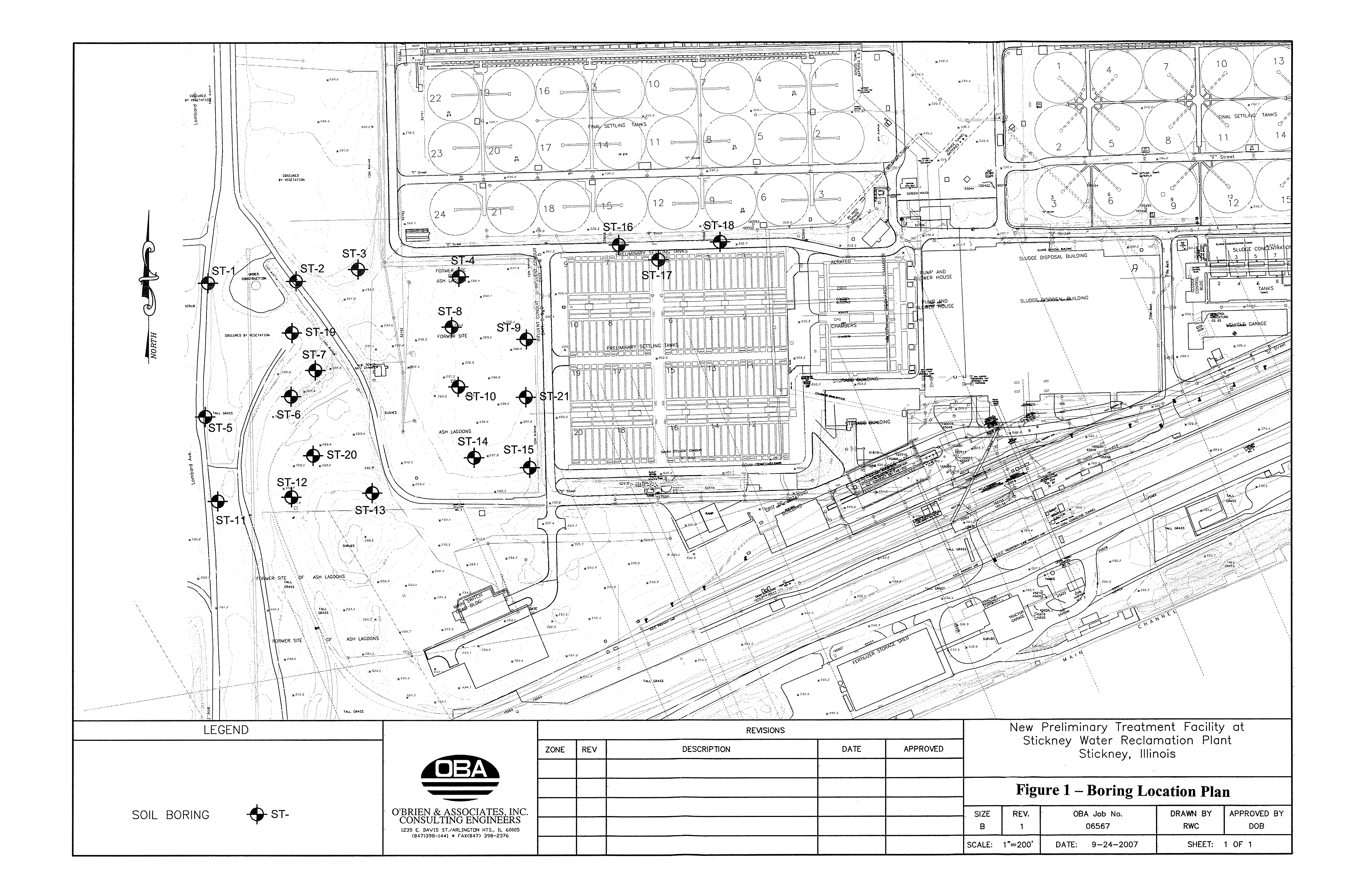
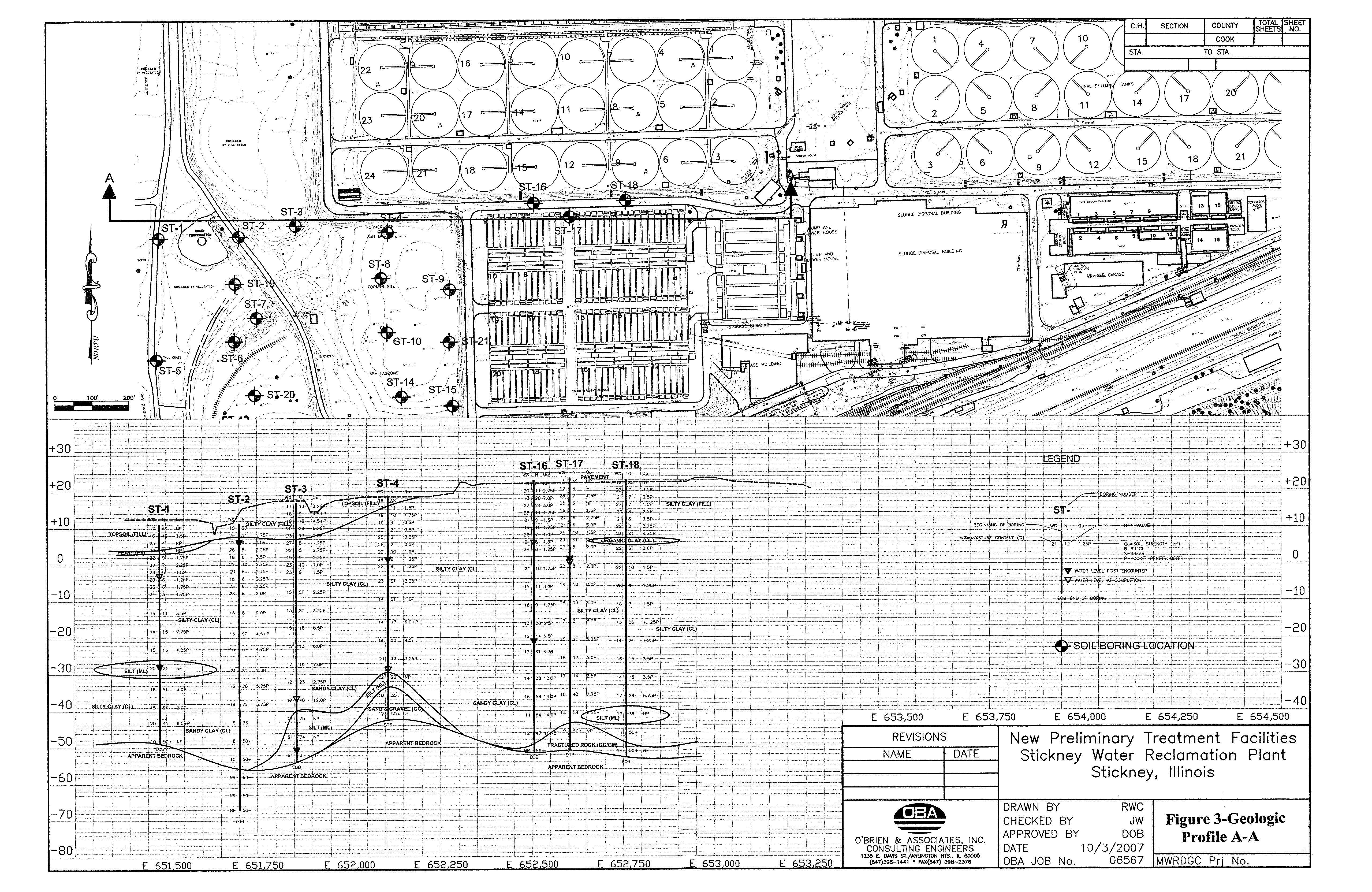
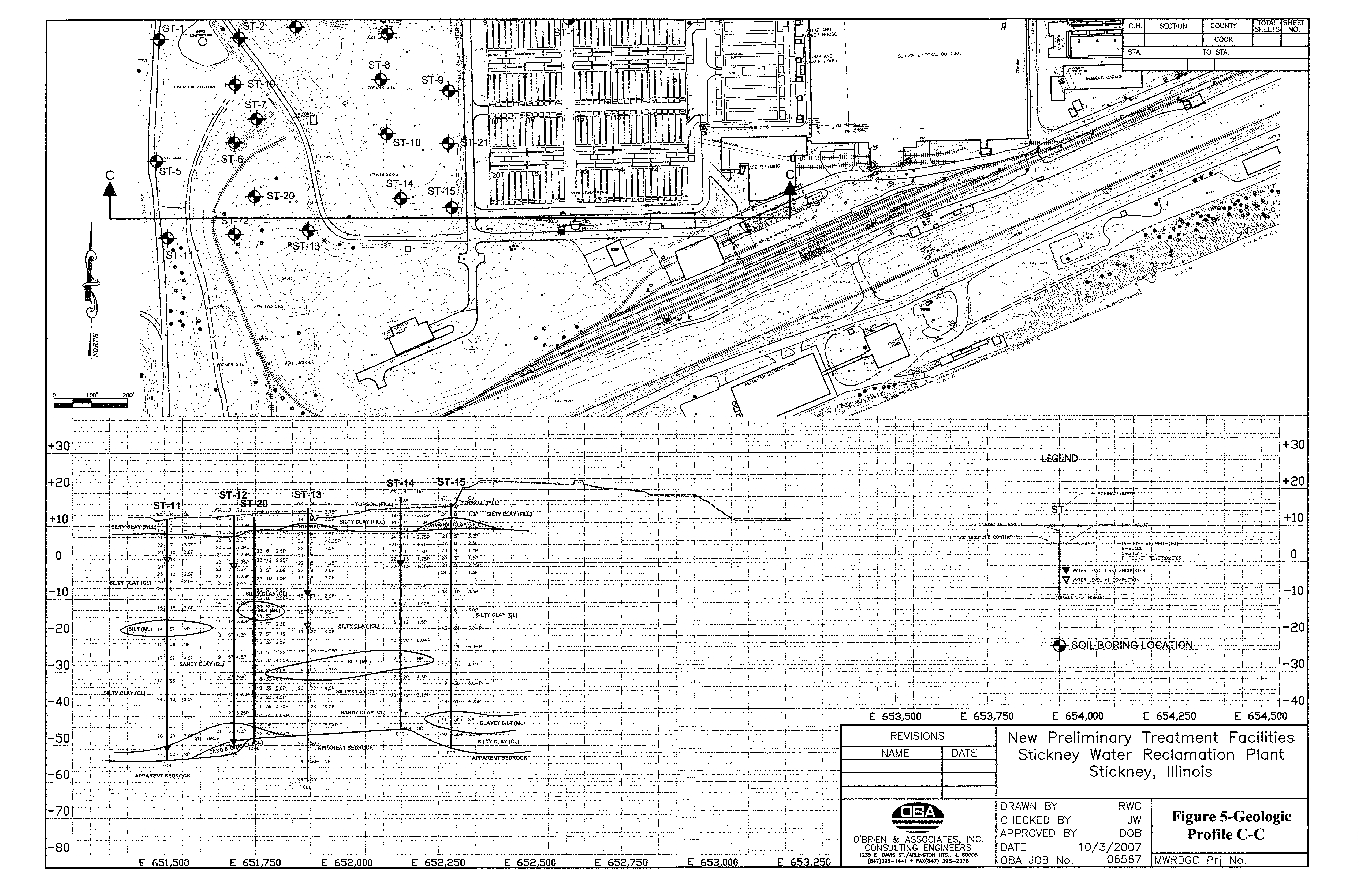
- 4.1.5 Geotechnical Information
- 5.0 SWRP STRUCTURAL AND ARCHITECTURAL
- 5.1.1 Codes and Specifications
- 5.1.2 Loads
- 5.1.3 Design Stresses
- 5.1.4 General Design
- 6.0 SWRP ELECTRICAL
- Table 6.2-1 – Existing and Proposed SWRP Electrical Loads
- Item Value
- 6.9.1 Medium Voltage Switchgear
- Table 6.9.1-1 – Medium Voltage Switchgear Criteria
- Table 6.9.1-2 – Circuit Breaker Ratings and Features Criteria
- Item Criteria
- Table 6.9.1-3 – Circuit Breaker Battery Criteria
- Item Criteria
- 6.9.2 Secondary Unit Substation
- Table 6.9.2-1 – Secondary Unit Substation
- Item Criteria
- Table 6.9.3-1 – Motor Control Center Criteria
- Item Criteria
- Item Criteria
- 8.0 SWRP MECHANICAL AND PLUMBING
- 8.2.1 Ventilation Rates
- Table 10.0-1 – SWRP UV Disinfection Facilities Preliminary OPCC and M&O Costs
- Capital Cost Estimates
- Total Present Worth $542,930,000
- Table 10.2-1 – M&O Labor Requirements
- Activity Labor Type Number Hours per Week
- per Worker
- Low Lift Pump Station
- Table 10.4-1 – OPCC Selected Line Item Description
- APPENDIX A
- HYDRAULIC TECHNICAL MEMORANDUM
- DISINFECTION?COST?STUDY
- HYDRAULIC?EVALUATION
- METROPOLITAN?WATER?RECLAMATION
- DISTRICT?OF?GREATER?CHICAGO
- STICKNEY?WATER?RECLAMATION?PLANT
- TECHNICAL?MEMORANDUM
- June?2,?2008
- 303?EAST?WACKER?DRIVE,?SUITE?600
- CHICAGO,?ILLINOIS?60601
- MWRDGC?Project?No.?07-026-2P
- CTE?Project?No.?60040695
- TABLE?OF?CONTENTS
- LIST?OF?TABLES
- LIST?OF?FIGURES
- LIST?OF?APPENDICES
- 1 INTRODUCTION
- 1.1?? Objective
- 2 PROPOSED?FACILITIES
- 2.1.1?Site?Constraints
- Conditions
- 3 HYDRAULIC?ANALYSIS?OF?THE?UV?DISINFECTION?FACILITIES
- 4 UV?DISINFECTION?FACILITIES
- Table?3?–?Design?Parameters?for?UV?Disinfection?Unit?at?NSWRP
- Parameter Design?Value
- 5 LOW?LIFT?PUMP?STATION
- Table?4?-?Low?Lift?Pump?Station?Basis?of?Design
- Pumps
- Table?5?-?Summary?of?Pump?Operation
- Flow,?MGD Pump?Drive?Type Pump?Flow,?gpm
- APPENDIX?A
- Site?Plan?from?the?SWRP?Master?Plan
- APPENDIX?B
- Selected?Pages?from?USACE?CUP?DDR
- APPENDIX?CLLPS?Proposed?Layout
- APPENDIX B
- NORTH SIDE WRP UV TECHNOLOGY
- TECHNICAL MEMORANDUM
- DISINFECTION?COST?STUDYULTRAVIOLET?DISINFECTION?TECHNOLOGY
- EVALUATION
- METROPOLITAN?WATER?RECLAMATION
- DISTRICT?OF?GREATER?CHICAGO
- NORTH?SIDE?WATER?RECLAMATION?PLANT
- TECHNICAL?MEMORANDUM
- OCTOBER?23,?2007
- TABLE?OF?CONTENTS
- LIST?OF?TABLES
- LIST?OF?FIGURES
- LIST?OF?APPENDICES
- Appendix Content
- INTRODUCTION
- Background
- Objective
- AVAILABLE?UV?DISINFECTION?TECHNOLOGIES
- Figure?1?–?Categories?of?Currently?Available?UV?Disinfection?Systems?(Hunter,?et
- al.,?2006b)
- Low?Pressure?–?Low?Intensity?(LP-LI)
- Open?ChannelHorizontal
- Lamps?parallel?to?flow
- Closed?Channel
- Horizontal
- Lamps
- perpendicular?to
- HorizontalLamps?parallel?to?flow
- Vertical
- Horizontal Vertical
- Table?1?–?Typical?UV?Technology?Categories?(Bazzazieh,?2005)
- UV?System Low?Pressure,
- Low?Intensity
- Low?Pressure,High?Intensity
- Medium?Pressure,High?Intensity
- Low?Pressure?–?High?Intensity?(LP-HI)
- Medium?Pressure?–?High?Intensity?(MP-HI)
- LITERATURE?REVIEW?OF?SELECTED?MP-HI?UV?TECHNOLOGY
- Typical?MP-HI?System?Configuration
- Influent?Characteristics
- Reactor?Configuration?and?Hydraulics
- Lamps?and?UV?Intensity?Control
- Lamp?Fouling?and?Cleaning
- Process?Control
- Safety
- REVIEW?OF?AVAILABLE?TECHNOLOGIES?FROM?MANUFACTURERS
- Trojan?Technologies?–?Trojan?UV4000™Plus
- Figure?2?–?UV4000+?System(Courtesy?of?Trojan?Technologies)
- Aquionics?–?InLine50,000+
- Figure?3?–?InLine50,000+?System
- (Courtesy?of?Aquionics)
- Calgon?Carbon?–?C
- 3500™
- Figure?4?–?TAK25?System
- (Courtesy?of?ITT/Wedeco)
- Severn?Trent?Services?(STS)/Quay?–?MicroDynamics™
- Figure?5?–?MicroDynamics?System
- (Courtesy?of?STS/Quay)
- Table?2.?Summary?of?Manufacturer-recommended?UV?Technologies?for?NSWRP
- Troanj
- Technologies
- Aquionics Calgon?Carbon? STS/Quay
- REFERENCE?INFORMATION?FROM?OTHER?OPERATING?FACILITIES
- Table?3.?Basis?of?Design?–?Clayton?WRC
- Telephone?Survey?of?Experience?at?Other?Facilities
- Facility Racine?WWTP R.L.Sutton?WRF Grand?Rapids
- Jacksonville?WWTP? Valley?Creek?WWTP
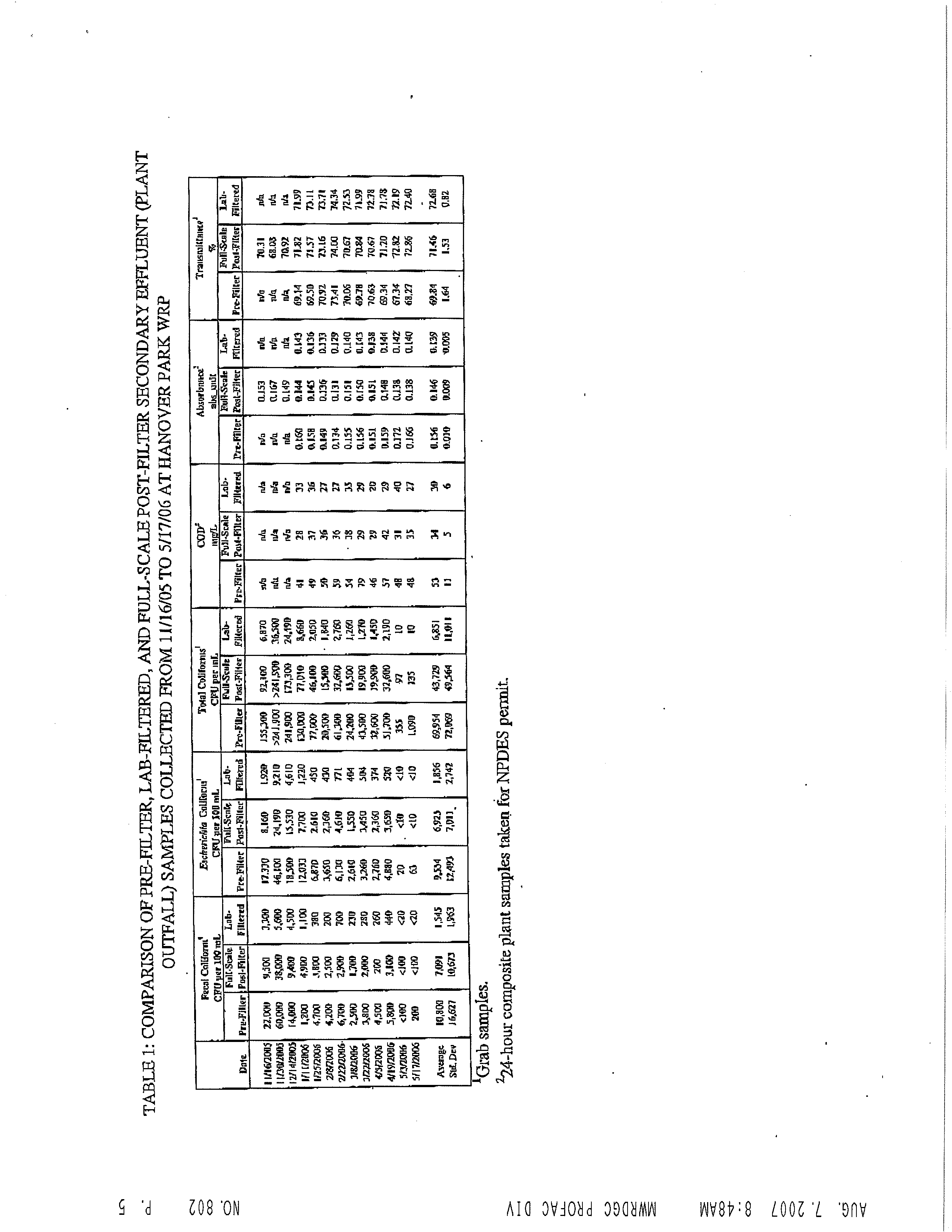
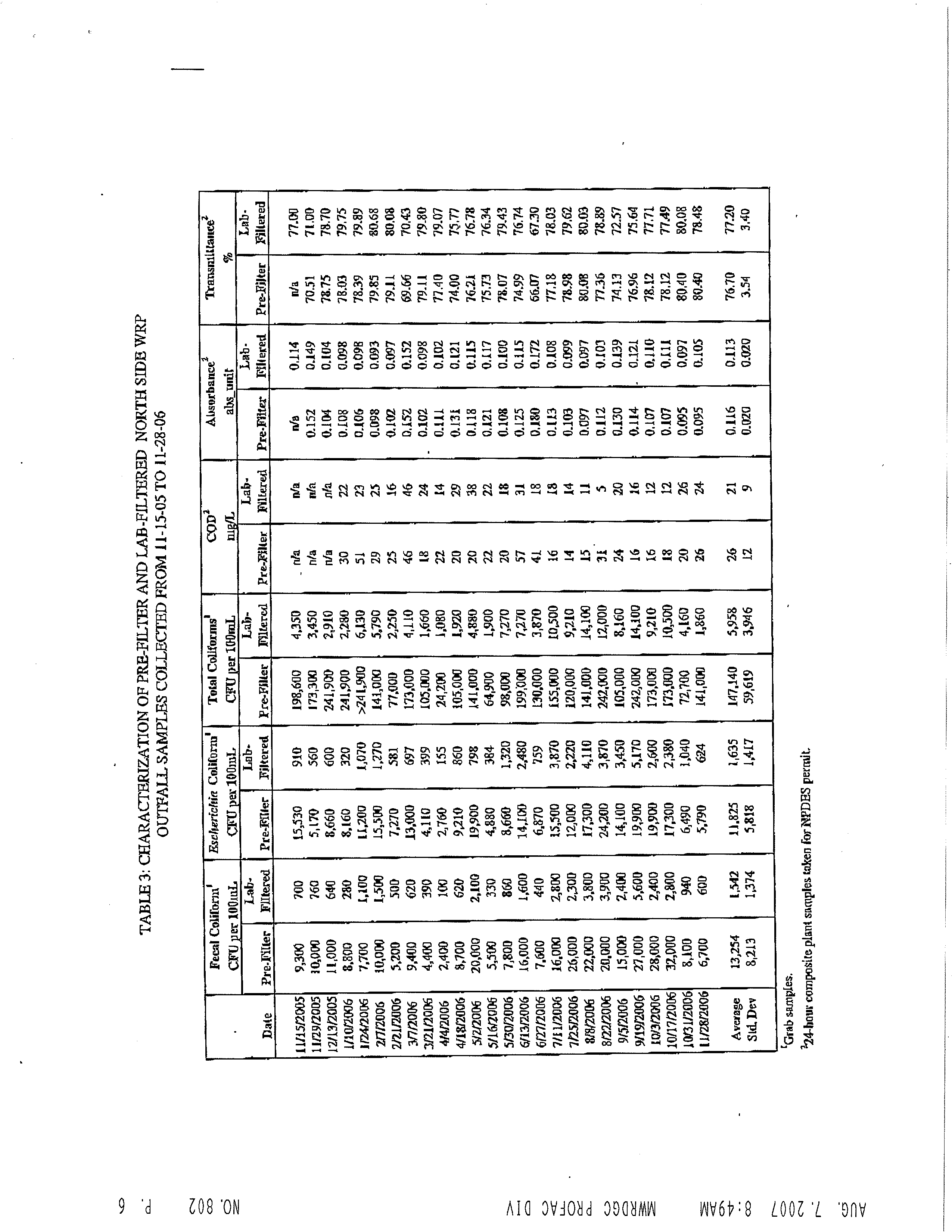
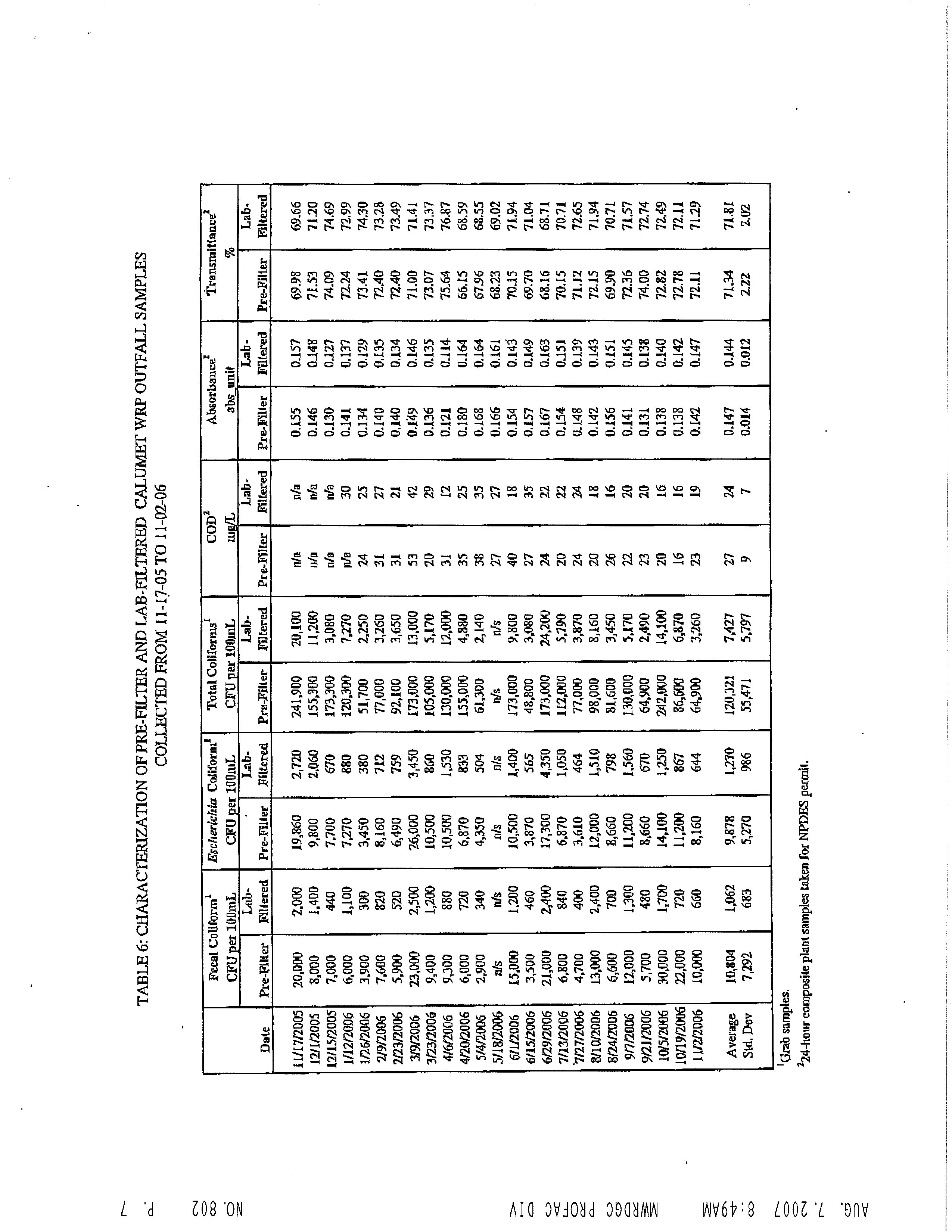
- Table?6.?Summary?of?2006/2007?Water?Quality?Testing
- Fecal
- 1E.ColiTotalColiformCODUV
- Site Transmittance
- NSWRP
- Need?for?Pilot?Testing
- BASIS?OF?DESIGN?OF?UV?SYSTEM?FOR?NORTH?SIDE?WRP
- Table?7.?Design?Parameters?for?UV?Disinfection?Unit?at?NSWRP
- Parameter Design?Value
- REFERENCES
- APPENDIX?A
- 2006?UV?TRIAL?WATER?QUALITY?DATA
- NSWRP,?CWRP,?AND?HPWRP
- APPENDIX C
- UV EQUIPMENT TECHNICAL INFORMATION
- www.trojanuv.com
- APPENDIX D
- PUMP TECHNICAL INFORMATION
- Pump Performance
- Pump Performance
- Pump Performance
- Pump Performance
- Pump Performance
- Pump Performance
- APPENDIX E
- DRAFT GEOTECHNICAL DESIGN REPORT
- FOR NEW PRELIMINARY TREATMENT FACILITIES AT STICKNEY
- AND CALUMET WRPS
- Draft Geotechnical Design Report for Stickney WRP Phase I & IA
- New Preliminary Treatment Facilities
- at Stickney and Calumet WRPs
- Contract No. 04-823-3P
- 1.0 GENERAL
- 2.0 PROJECT DESCRIPTION
- 3.0 PROJECT DATUM
- 4.0 SITE INVESTIGATION
- Boring
- GroundSurfaceElevation
- Depth ofBoring(ft)
- Depth toGroundwater
- GroundwaterElevation
- Top of
- BedrockElevation
- 5.0 SITE CONDITIONS
- 6.0 REGIONAL GEOLOGY
- 7.0 SUBSURFACE CONDITIONS
- 8.0 GROUNDWATER EVALUATION
- Groundwater Elevation
- Date of Reading
- Adjacent to ST-1Ground EL +11.6
- Obs. Well W-2Adjacent to ST-12Ground EL 13.8
- Obs. Well W-3Adjacent to ST-
- Ground EL 18.5
- 9.0 TESTING
- 10.0 ENVIRONMENTAL ASSESSMENT OF ASH LAGOONS
- 11.0 GEOTECHNICAL DESIGN PARAMETERS
- 12.0 PROPOSED FACILITY FOUNDATION INFORMATION
- 13.0 FOUNDATION TYPE OF EXISTING FACILITY STRUCTURES
- 14.0 PRELIMINARY GEOTECHNICAL RECOMMENDATIONS
- 15.0 CONSTRUCTION CONSIDERATIONS
- 16.0 PROPOSED PHASE II INVESTIGATIONS
- 17.0 LIMITATIONS
- 18.0 REFERENCES
- APPENDIX F
- COST ESTIMATE BREAKDOWN TABLES
- APPENDIX G
- ELECTRICAL EVALUATION TECHNICAL MEMORANDUM
- DISINFECTION COST STUDY
- ELECTRICAL EVALUATION
- METROPOLITAN WATER RECLAMATION
- DISTRICT OF GREATER CHICAGO
- STICKNEY WATER RECLAMATION PLANT
- TECHNICAL MEMORANDUM
- August 1, 2008
- 303 EAST WACKER DRIVE, SUITE 600
- CHICAGO, ILLINOIS 60601
- MWRDGC Project No. 07-026-2P
- CTE Project No. 60040695
- TABLE OF CONTENTS
- LIST OF TABLES
- APPENDICES
- 2.0 OBJECTIVE
- 4.0 ELECTRICAL BASIS OF DESIGN
- 4.1 Electric Service
- Table 1 Existing and Proposed SWRP Electrical Loads
- Item Value
- 4.2 System Grounding
- 4.3 Conduit
- 4.7 Lightning Protection
- 4.8 Specific Electrical Equipment
- Table 2 Medium Voltage Switchgear Criteria
- Item Criteria
- Criteria
- Table 3 Circuit Breaker Ratings and Features Criteria
- Item Criteria
- Table 4 Circuit Breaker Battery Criteria
- Item Criteria
- Table 6 Motor Control Center Criteria
- Item Criteria
|
BEFORE THE ILLINOIS POLLUTION CONTROL BOARD
IN THE MATTER OF:
WATER QUALITY STANDARDS AND
EFFLUENT LIMITATIONS FOR THE
CHICAGO AREA WATERWAY SYSTEM
AND THE LOWER DES PLAINES RIVER:
PROPOSED AMENDMENTS TO 35 Ill.
Adm. Code Parts 301, 302, 303 and 304
)
)
)
)
)
)
)
)
R08-9
(Rulemaking - Water)
NOTICE OF FILING
To:
ALL COUNSEL OF RECORD
(Service List Attached)
PLEASE TAKE NOTICE
that on the 20th day of October, 2008, I electronically filed
with the Office of the Clerk of the Illinois Pollution Control Board the following documents on
behalf of the Metropolitan Water Reclamation District of Greater Chicago:
1.
UV Disinfection Cost Study (Stickney Water Reclamation Plant) Volume I
2.
UV Disinfection Cost Study (Stickney Water Reclamation Plant) Volume II
3.
UV Disinfection Cost Study (North Side Water Reclamation Plant) Volume I
(also discussing Calumet Water Reclamation Plant)
4.
UV Disinfection Cost Study (North Side Water Reclamation Plant) Volume II
(also discussing Calumet Water Reclamation Plant)
5.
Hydraulic Technical Memorandum - Appendix A for North Side Water
Reclamation Plan UV Disinfection Cost Study
6.
UV Technology Technical Memorandum - Appendix B for North Side Water
Reclamation Plan UV Disinfection Cost Study
7.
UV Equipment Technical Information - Appendix C for North Side Water
Reclamation Plan UV Disinfection Cost Study
8.
Pump Technical Information - Appendix D for North Side Water Reclamation
Plan UV Disinfection Cost Study
Electronic Filing - Received, Clerk's Office, Octobr 20, 2008
[This filing submitted on recycled paper as defined in 35 Ill. Adm. Code 101.202]
2
9.
Historic Soil Boring Information - Appendix E for North Side Water Reclamation
Plan UV Disinfection Cost Study
10.
Cost Estimate Breakdown Tables - Appendix F for North Side Water Reclamation
Plan UV Disinfection Cost Study
11.
Disinfection Cost Study Hydraulic Evaluation - Technical Memorandum
(Stickney Water Reclamation Plant)
Dated: October 20, 2008
METROPOLITAN WATER RECLAMATION
DISTRICT OF GREATER CHICAGO
By:
/s/ David T. Ballard
One of Its Attorneys
Fredric P. Andes
David T. Ballard
BARNES & THORNBURG LLP
Suite 4400
One North Wacker Drive
Chicago, Illinois 60606
(312) 357-1313
Electronic Filing - Received, Clerk's Office, Octobr 20, 2008
[This filing submitted on recycled paper as defined in 35 Ill. Adm. Code 101.202]
3
PROOF OF SERVICE
The undersigned, a non-attorney, certifies, under penalties of perjury pursuant to 735
ILCS 5/1-109, that I caused a copy of the forgoing, Notice of Filing, to be served via First Class
Mail, postage prepaid, from One North Wacker Drive, Chicago, Illinois, on the 20th day of
October, 2008, upon the attorneys of record on the attached Service List.
/s/ Barbara E. Szynalik
Barbara E. Szynalik
Electronic Filing - Received, Clerk's Office, Octobr 20, 2008
[This filing submitted on recycled paper as defined in 35 Ill. Adm. Code 101.202]
4
SERVICE LIST
R08-9 (Rulemaking - Water)
Richard J. Kissel
Roy M. Harsch
Drinker, Biddle, Gardner, Carton
Suite 3700
191 N. Wacker Drive
Chicago, IL 60606-1698
Claire A. Manning
Brown, Hay & Stephens LLP
700 First Mercantile Bank Building
205 South Fifth St., P.O. Box 2459
Springfield, IL 62705-2459
Deborah J. Williams, Assistant Counsel
Stefanie N. Diers, Assistant Counsel
IEPA
Division of Legal Counsel
1021 North Grand Avenue East
P.O. Box 19276
Springfield, IL 62794-9276
Katherine D. Hodge
Monica T. Rios
Matthew C. Read
Hodge Dwyer Zeman
3150 Roland Avenue
P.O. Box 5776
Springfield, IL 62705-5776
Kevin G. Desharnais
Thomas W. Dimond
Thomas V. Skinner
Mayer, Brown LLP
71 South Wacker Drive
Chicago, IL 60606-4637
Charles W. Wesselhoft
James T. Harrington
McGuireWoods LLP
Suite 4100
77 West Wacker Drive
Chicago, IL 60601-1818
Robert VanGyseghem
City of Geneva
1800 South Street
Geneva, IL 60134-2203
Jerry Paulsen
Cindy Skrukrud
McHenry County Defenders
132 Cass Street
Woodstock, IL 60098
Matthew J. Dunn, Chief
Office of the Attorney General
Environmental Bureau North
Suite 1800
69 West Washington Street
Chicago, IL 60602
Kevin B. Hynes
O’Keefe Lyons & Hynes, LLC
Suite 4100
30 North LaSalle Street
Chicago, Illinois 60602
Bernard Sawyer
Thomas Granto
Metropolitan Water Reclamation District
6001 W. Pershing Road
Cicero, IL 60804
Lisa Frede
Chemical Industry Council of Illinois
Suite 239
2250 East Devon Avenue
Des Plaines, IL 60018-4509
James L. Daugherty, District Manager
Sharon Neal
Electronic Filing - Received, Clerk's Office, Octobr 20, 2008
[This filing submitted on recycled paper as defined in 35 Ill. Adm. Code 101.202]
5
Thorn Creek Basin Sanitary District
700 West End Avenue
Chicago Heights, IL 60411
Commonwealth Edison Company
125 South Clark Street
Chicago, IL 60603
Tracy Elzemeyer, General Counsel
American Water Company Central Region
727 Craig Road
St. Louis, MO 63141
Margaret P. Howard
Hedinger Law Office
2601 South Fifth Street
Springfield, IL 62703
Keith I. Harley
Elizabeth Schenkier
Chicago Legal Clinic, Inc.
4
th
Floor
205 West Monroe Street
Chicago, IL 60606
Frederick D. Keady, P.E., President
Vermilion Coal Company
1979 Johns Drive
Glenview, IL 60025
Roy G. Wilcox
Attorney at Law
16 West Madison
P.O. Box 12
Danville, IL 61834
Georgia Vlahos
Naval Training Center
2601A Paul Jones Street
Great Lakes, IL 60088-2845
W.C. Blanton
Blackwell Sanders LLP
Suite 1000
4801 Main Street
Kansas City, MO 64112
Dennis L. Duffield
Director of Public Works & Utilities
City of Joliet, Department of Public
Works & Utilities
921 E. Washington Street
Joliet, IL 60431
Traci Barkley
Prarie Rivers Networks
Suite 6
1902 Fox Drive
Champaign, IL 61820
Ann Alexander, Sr. Attorney
Natural Resources Defense Council
Suite 609
101 North Wacker Drive
Chicago, IL 60606
James Huff, Vice President
Huff & Huff, Inc.
Suite 3300
915 Harger Road
Oak Brook, IL 60523
Beth Steinhorn
2021 Timberbrook
Springfield, IL 62702
Electronic Filing - Received, Clerk's Office, Octobr 20, 2008
[This filing submitted on recycled paper as defined in 35 Ill. Adm. Code 101.202]
6
Cathy Hudzik
City of Chicago - Mayor's Office of
Intergovernmental Affairs
City Hall - Room 406
121 N. LaSalle Street
Chicago, IL 60602
Dr. Thomas J. Murphy
DePaul University
2325 N. Clifton Street
Chicago, IL 60614
Irwin Polls
Ecological Monitoring and Assessment
3206 Maple Leaf Drive
Glenview, IL 60025
Susan M. Franzetti
Franzetti Law Firm P.C.
Suite 3600
10 S. LaSalle Street
Chicago, IL 60603
Marc Miller, Senior Policy Advisor
Jamie S. Caston, Policy Advisor
Office of Lt. Governor Pat Quinn
Room 414 State House
Springfield, IL 62706
Vicky McKinley
Evanston Environment Board
223 Grey Avenue
Evanston, IL 60202
Albert Ettinger, Senior Staff Attorney
Jessica Dexter
Environmental Law & Policy Center
Suite 1300
35 E. Wacker Drive
Chicago, IL 60601
Kenneth W. Liss
Andrews Environmental Engineering
3300 Ginger Creek Drive
Springfield, IL 62711
Tom Muth
Fox Metro Water Reclamation District
682 State Route 31
Oswego, IL 60543
Bob Carter
Bloomington Normal Water
Reclamation District
P.O. Box 3307
Bloomington, IL 61702-3307
Jack Darin
Sierra Club
Illinois Chapter
Suite 1500
70 E. Lake Street
Chicago, IL 60601-7447
Kay Anderson
American Bottoms RWTF
One American Bottoms Road
Sauget, IL 62201
Electronic Filing - Received, Clerk's Office, Octobr 20, 2008
[This filing submitted on recycled paper as defined in 35 Ill. Adm. Code 101.202]
7
Marie Tipsord, Hearing Officer
John Therriault, Assistant Clerk
Illinois Pollution Control Board
100 W. Randolph Street
Suite 11-500
Chicago, IL 60601
Kristy A. N. Bulleit
Brent Fewell
Hunton & Williams LLC
1900 K Street, NW
Washington, DC 20006
Stacy Meyers-Glen
Openlands
Suite 1650
25 East Washington
Chicago, Illinois 60602
Jeffrey C. Fort
Ariel J. Tesher
Sonnenschein Nath & Rosenthal LLP
7800 Sears Tower
233 S. Wacker Drive
Chicago, IL 60606-6404
Susan Hedman
Andrew Armstrong
Environmental Counsel Environmental Bureau
Suite 1800
69 West Washington Street
Chicago, IL 60602
Ronald M. Hill
Margaret T. Conway
Metropolitan Water Reclamation District of
Greater Chicago
100 E. Erie Street, Room 301
Chicago, Illinois 60611
Alec M. Davis
General Counsel
Illinois Environmental Regulatory Group
215 East Adams Street
Springfield, IL 62701
503739
Electronic Filing - Received, Clerk's Office, Octobr 20, 2008
UV DISINFECTION COST STUDY
Cost Study Report
FOR
METROPOLITAN WATER RECLAMATION
DISTRICT OF GREATER CHICAGO
VOLUME 1 OF 2
STICKNEY WATER RECLAMATION PLANT
September 9, 2008
Prepared By
303 EAST WACKER DRIVE, SUITE 600
CHICAGO, ILLINOIS 60601
MWRDGC Project No. 07-026-2P
CTE Project No. 60026610
Electronic Filing - Received, Clerk's Office, Octobr 20, 2008
i
TABLE OF CONTENTS
Volume 1 – Report and Appendices
EXECUTIVE SUMMARY ............................................................................................................. 1
Introduction .............................................................................................................................1
Objectives ...............................................................................................................................1
Proposed Facilities ..................................................................................................................1
Hydraulics ...............................................................................................................................2
Disinfection Technology...........................................................................................................2
Site Layout ..............................................................................................................................2
Preliminary Cost Opinion .........................................................................................................3
1.0
INTRODUCTION ............................................................................................................ 5
1.1
Background ................................................................................................................5
1.2
Objective ....................................................................................................................5
1.3
General Design Standards..........................................................................................5
1.4
Organization of this Report .........................................................................................6
2.0
HYDRAULICS ................................................................................................................ 6
2.1
Hydraulic Analysis of the UV Disinfection Facilities .....................................................6
2.2.1
Objectives ..............................................................................................................6
2.2.2
Overview ................................................................................................................6
2.3
Assumptions...............................................................................................................7
2.4
Results .......................................................................................................................8
2.5
Conclusion .................................................................................................................8
3.0
SWRP DISINFECTION PROCESS ............................................................................... 10
3.1
Introduction .............................................................................................................. 10
3.2
UV Disinfection System ............................................................................................ 10
3.2.1
Background .......................................................................................................... 10
3.2.2
Basis of Design .................................................................................................... 11
3.2.3
Process Control .................................................................................................... 12
3.2.4
Safety................................................................................................................... 13
3.2.5
Proposed Design Criteria for UV Disinfection Equipment ...................................... 13
3.3
Low Lift Pump Station............................................................................................... 15
3.3.1
Basis of Design .................................................................................................... 15
3.3.2
Pump Type........................................................................................................... 15
3.3.3
Proposed Operational Description ........................................................................ 16
3.3.4
Proposed Layout .................................................................................................. 16
4.0
SWRP CIVIL................................................................................................................. 17
4.1
Basis of Design......................................................................................................... 18
4.1.1
Roadways and Other Site Improvements .............................................................. 18
4.1.2
Junction Chamber/Effluent Conduits ..................................................................... 18
4.1.3
Site Utilities .......................................................................................................... 19
4.1.5
Geotechnical Information...................................................................................... 19
5.0
SWRP STRUCTURAL AND ARCHITECTURAL............................................................ 20
5.1
Introduction .............................................................................................................. 20
5.1.1
Codes and Specifications ..................................................................................... 20
5.1.2
Loads ................................................................................................................... 21
5.1.3
Design Stresses ................................................................................................... 22
5.1.4
General Design .................................................................................................... 23
5.1.5
Foundation Design ............................................................................................... 23
5.2
SWRP UV Facility..................................................................................................... 23
5.3
Low Lift Pump Station............................................................................................... 24
6.0
SWRP ELECTRICAL .................................................................................................... 24
6.1
Codes/Standards ...................................................................................................... 24
6.2
Electric Service......................................................................................................... 25
Electronic Filing - Received, Clerk's Office, Octobr 20, 2008
ii
6.3
System Grounding.................................................................................................... 25
6.4
Conduit..................................................................................................................... 25
6.5
Wire ......................................................................................................................... 25
6.6
Motors (Except Low Lift Pump Motors)...................................................................... 26
6.7
Emergency Systems................................................................................................. 26
6.8
Lightning Protection .................................................................................................. 26
6.9
Specific Electrical Equipment .................................................................................... 26
6.9.1
Medium Voltage Switchgear ................................................................................. 26
6.9.2
Secondary Unit Substation ................................................................................... 28
6.9.3
Motor Control Centers .......................................................................................... 28
7.0
SWRP INSTRUMENTATION SYSTEM......................................................................... 29
7.1
Applicable Codes and Standards .............................................................................. 29
8.0
SWRP MECHANICAL AND PLUMBING ....................................................................... 30
8.1.
Mechanical Codes .................................................................................................... 30
8.2
Basis of Design......................................................................................................... 30
8.2.1
Ventilation Rates .................................................................................................. 30
8.2.2
Design Temperatures ........................................................................................... 30
8.2.3
Plumbing .............................................................................................................. 30
8.3
Proposed Mechanical and Plumbing System............................................................. 31
8.3.1
UV Disinfection Facility ......................................................................................... 31
8.3.2
Low Lift Pump Station........................................................................................... 31
9.0
SWRP AREAS REQUIRING FURTHER ANALYSIS...................................................... 32
10.0
SWRP PRELIMINARY COST OPINION........................................................................ 32
10.1
Basis of Opinion of Capital Cost................................................................................ 33
10.2
Basis of Operation and Maintenance Costs............................................................... 34
10.3
Basis of Net Present Value Calculation ..................................................................... 34
10.4
Discussion of Cost Estimate Line Items .................................................................... 35
LIST OF TABLES
Table ES-1 – SWRP UV Disinfection Facilities Preliminary OPCC and M&O Costs......................3
Table 2.4-1 – Summary of Proposed WSE including UV Disinfection Facilities.............................8
Figure 2.4-2 - Hydraulic Profile for Disinfection Cost Study ..........................................................9
Table 3.2-1 – Design Parameters for UV Disinfection Unit at SWRP .......................................... 13
Table 3.3-1 – Low Lift Pump Station Basis of Design ................................................................. 15
Table 3.3-2 – Examples of Pump Operation............................................................................... 16
Figure 3.3-1 - Proposed UV Disinfection Flow Diagram.............................................................. 17
Table 6.9.1-1 – Medium Voltage Switchgear Criteria.................................................................. 26
Table 6.9.1-2 – Circuit Breaker Ratings and Features Criteria.................................................... 27
Table 6.9.1-3 – Circuit Breaker Battery Criteria.......................................................................... 27
Table 6.9.2-1 – Secondary Unit Substation................................................................................ 28
Table 6.9.3-1 – Motor Control Center Criteria ............................................................................ 28
Table 10.0-1 – SWRP UV Disinfection Facilities Preliminary OPCC and M&O Costs.................. 33
Table 10.2-1 – M&O Labor Requirements.................................................................................. 34
Table 10.4-1 – OPCC Selected Line Item Description................................................................ 35
Electronic Filing - Received, Clerk's Office, Octobr 20, 2008
iii
LIST OF FIGURES
Figure ES 1- Proposed UV Facilities Flow Diagram .....................................................................3
Figure ES 2 - SWRP Proposed Site Plan.....................................................................................4
Figure 2.4-1 - Hydraulic Profile for Disinfection Cost Study ..........................................................9
Figure 3.3-1 - Proposed UV Disinfection Flow Diagram.............................................................. 17
LIST OF APPENDICES
Appendix A
Hydraulic Technical Memorandum
Appendix B
North Side WRP UV Technology Technical Memorandum
Appendix C
UV Equipment Technical Information
Appendix D
Pump Technical Information
Appendix E
Draft Geotechnical Design Report for New Preliminary Treatment Facilities at
Stickney and Calumet WRPs
Appendix F
Cost Estimate Breakdown Tables
Appendix G
Electrical Evaluation Technical Memorandum
Volume 2 – Conceptual Design Drawings
Electronic Filing - Received, Clerk's Office, Octobr 20, 2008
1
\\Uschg1fp207\p60040695\P60040695\500_Submittals\503_Cost
Study Report\503.1_Draft Report\Final_Cost_Study_Report_091008.doc
EXECUTIVE SUMMARY
Introduction
The Technical Memorandum 1WQ Disinfection Evaluation (TM1-WQ) was completed in August
2005 for the Metropolitan Water Reclamation District of Greater Chicago (MWRDGC or District)
as part a Water Quality (WQ) Strategy for affected Chicago Area Waterways. TM1-WQ reviewed
the alternative disinfection technologies available for use at the District’s North Side (NSWRP),
Calumet (CWRP) and Stickney Water Reclamation Plants (SWRP) and provided an initial
estimate of construction cost for the facilities. On the basis of that report, the District requested
further investigation into UV disinfection. The findings of the Preliminary Cost Opinion for
Ultraviolet (UV) Disinfection Facilities Study at the Stickney Water Reclamation Plant are
presented in this Report.
Objectives
This evaluation is based upon the TM1-WQ, the comments received from the USEPA as part of
the Use Attainability Analysis (UAA) evaluations, and new information obtained since the previous
work. The primary objectives of the evaluation presented in this report are:
x
To describe the conceptual facilities developed as part of this study including their basis of
design and the assumptions used for their development.
x
To develop a Level 3 Preliminary Opinion of Probable Construction Cost per the Association
for the Advancement of Cost Engineering recommended practices for the proposed facilities
at the SWRP, which represents an expectation that actual cost will deviate from the
estimated cost by -15% to 30%.
x
To develop annual maintenance and operations (M&O) costs for the conceptual facilities.
Proposed Facilities
This study reviewed the proposed facilities for the UV Disinfection Alternative in TM-1WQ
including the four primary components: Site work, a low lift pump station, tertiary filters and UV
disinfection. Through that review, it was determined that the low lift pump station and the tertiary
filters required re-evaluation.
At the time TM-1WQ was developed, very little information was available regarding the water
quality of the plant effluent as it related to ultraviolet light transmissivity, and the that data which
was available indicated low transmissivity levels. In TM-1WQ, tertiary filters were included in the
initial proposed facilities in order to improve disinfection effectiveness by removing components
that would inhibit the disinfection process. Since that time, additional water quality data was
collected for the NSWRP by the District during the North Side UV Disinfection Cost Study Report.
A review of that data indicated that the UV transmissivity is within the minimum range necessary
for UV disinfection without filtration. As a result, tertiary filters were not included in the North Side
Cost Study and are not included in the proposed disinfection facilities presented in this report.
However, the exclusion of tertiary filters from this report should not suggest that tertiary filters
may not be required in the future to meet stricter suspended solids or total phosphorous limits, or
that tertiary filters would not improve the effectiveness of a UV disinfection process. As
concluded in the SWRP Master Plan, space would be reserved on the site for future tertiary filter
faciilties.
As tertiary filters would not be required as part of the implementation of UV disinfection, the need
for a low lift pump station was questioned. Additional pumping would be required only if the head
loss added by the new UV Disinfection Facilities and associated flow conduits and flow splitting
structures exceeds the available head at the plant. To determine the required head through the
UV Disinfection facilities, a hydraulics evaluation was performed.
Electronic Filing - Received, Clerk's Office, Octobr 20, 2008
2
\\Uschg1fp207\p60040695\P60040695\500_Submittals\503_Cost
Study Report\503.1_Draft Report\Final_Cost_Study_Report_091008.doc
Hydraulics
Hydraulic modeling was not included as part of the Master Plan for Stickney WRP and so a
hydraulic model was developed for this report based on existing plant water levels as
documented in previous design projects as well as projected water levels in the Ship and Sanitary
Canal for a 100-year flood event based on the USACE’s CUP Report. This model was modified
to include the additional effluent conduits, gate structures, and UV channels/reactors required for
the new facilities. The model was used to determine the required head following implementation
of the new UV Disinfection Facilities.
The results of this evaluation showed that the projected head required through the proposed UV
facilities exceeds the head available at the plant by over 8.7-ft and confirms the need for a Low
Lift Pump Station (LLPS) in order to convey the peak flow of 1,440 MGD through the UV facilities
at the 100-year flood elevation.
Disinfection Technology
The Trojan UV4000™Plus system, which utilizes medium pressure, high intensity type UV lamps,
was used to develop the basis of design for the UV disinfection system at the SWRP. This type of
UV system was selected due to the lower number of lamps required compared to other systems
and based upon the recommendations of a team of disinfection experts that evaluated the
available disinfection technologies during the Master Plan effort.
During the NSWRP UV Disinfection Cost Study, the details of the implementation of this UV
technology were updated by consultation with the manufacturer and incorporated into the basis of
design. In addition, a phone survey of other facilities of similar size and source water quality was
conducted. This survey revealed several important conclusions including the following:
x
When using ferric salt addition for improved settleability of solids or phosphorus removal
in the treatment process upstream of UV disinfection, an increase in the fouling rate was
experienced.
x
The level of maintenance and operations efforts was highly variable and site specific,
even with plants using the same technology and source water.
x
The most effective method of power control for the UV system is highly site specific and
has a great impact on the disinfection effectiveness and the energy effectiveness of the
system.
Due to the size of the proposed SWRP UV Disinfection Facilities, which would be among the
largest continually-operating UV disinfection systems in the world, CTE recommends the District
undertake an extensive program which includes review of system specific independent validation
studies, collimated beam testing, UV transmittance testing and a reasonably sized pilot facility.
This program would determine, among other factors, the following information in-situ:
x
Appropriate control sequences and optimization for the UV disinfection equipment,
including appropriate sensing equipment to allow advanced power management.
x
In-situ disinfection performance including fouling rates or the lamps with and without ferric
salt addition.
x
Actual M&O requirements in terms of labor and consumables as well as space
requirements to complete required maintenance activities.
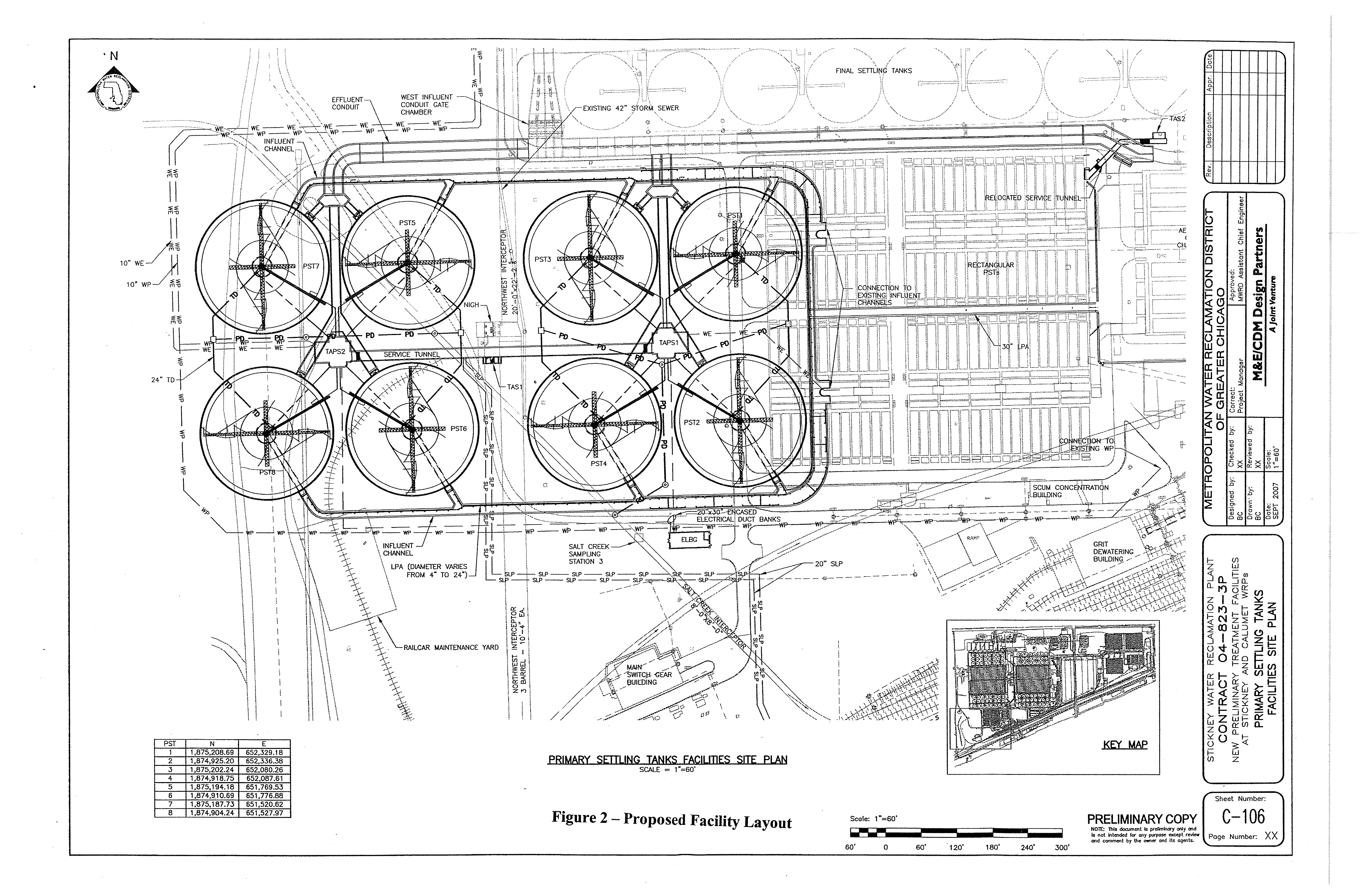
Site Layout
As part of the study, a proposed layout of the disinfection facilities at the SWRP was developed
including the Low Lift Pump Station, UV Disinfection Facilities, related gate structures/effluent
conduits and space reserved for future tertiary filters.
Figure ES-2
and Volume 2 of this report
show the proposed site layout while
Figure ES-1
shows the proposed flow diagram for the new
UV Disinfection Facilities.
Electronic Filing - Received, Clerk's Office, Octobr 20, 2008
3
\\Uschg1fp207\p60040695\P60040695\500_Submittals\503_Cost
Study Report\503.1_Draft Report\Final_Cost_Study_Report_091008.doc
Figure ES 1 - Proposed UV Facilities Flow Diagram
Due to the limited space available upstream of the existing outfall, flow would be directed
approximately 1,800-ft to the new facilities located to the southwest of the site. As a result of the
location of the new facilities, it is recommended that a new plant outfall to the Ship and Sanitary
Canal be constructed directly south of the new facilities (and west of the existing outfall) in lieu of
installing an extensive return conduit back to the existing outfall. It should be noted that the new
outfall would require permitting through the United States Army Corps of Engineers (USACE) and
others. The cost of this new outfall is included in the cost opinion.
Preliminary Cost Opinion
The preliminary opinion of probable construction cost (OPCC) for SWRP UV Disinfection
Fac ilities is shown
Tab
in
le ES-1
below. As shown, the projected construction cost for the SWRP
UV Disinfection facilities is $542.9 million. The details of the basis of design for the proposed
facilities and the methods of developing the OPCC are presented in the body of this report.
Table ES-1 – SWRP UV Disinfection Facilities Preliminary OPCC and M&O Costs
Capital Cost Estimates
A. General Sitework
$61,890,000
B. Low Lift Pump Station
$86,220,000
C. Disinfection System
$112,420,000
Total Capital Cost
$260,530,000
Maintenance & Operations Cost Estimates
A. General Sitework
$90,000/yr
B. Low Lift Pump Station
$2,540,000/yr
C. Disinfection System
$9,560,000/yr
Total Annual M&O Cost
$12,190,000/yr
Total Present Worth M&O Cost
$282,400,000
Total Present Worth
$542,930,000
All costs in 2007 dollars.
E x isting
Plant
LLPS
UV
Facilities
Future
Tertiary
Filters
New
Outfall
E x isting
Outfall
Q=1,440
MGD
(Winter Operation)
Junction
Chamber
Electronic Filing - Received, Clerk's Office, Octobr 20, 2008
N
NOT FOR CONSTRUCTION
Electronic Filing - Received, Clerk's Office, Octobr 20, 2008
5
\\Uschg1fp207\p60040695\P60040695\500_Submittals\503_Cost
Study Report\503.1_Draft Report\Final_Cost_Study_Report_091008.doc
1.0
INTRODUCTION
1.1
Background
This report has been developed to present the findings of the Preliminary Cost Opinion for
Ultraviolet (UV) Disinfection Facilities Study at the Metropolitan Water Reclamation District of
Greater Chicago’s (MWRDGC, or District) Stickney Water Reclamation Plant (SWRP) in
Stickney, Illinois. This report continues the work began in TM1-WQ, which was developed
previously as part of the comprehensive Infrastructure and Process Needs Feasibility Study
(Master Plan) for the SWRP and a Water Quality (WQ) Strategy for affected Chicago Area
Waterways.
The TM1-WQ documented the results of a CTE study of effluent disinfection alternatives for the
District’s North Side, Calumet and Stickney WRPs. In that study, a task force of national experts
(referred to as the Blue Ribbon Panel) reviewed available disinfection technologies and their
range of pathogen destruction efficiency, disinfection byproducts and impacts upon aquatic life
and human health. Their investigation also included an examination of the environmental and
human health impacts of the energy required for the operation of the facility and for the
processing and production of process chemicals. Based on economic and non-economic
evaluation of alternatives, ozone disinfection and UV disinfection were selected and preliminary
design and cost estimates were developed. Based on the results of that subsequent evaluation,
the District determined that UV disinfection is the most cost-effective alternative.
1.2
Objective
The District has requested further evaluation of the UV disinfection technology. This additional
evaluation is based on the TM-1WQ, the comments received from the United States
Environmental Protection Agency (USEPA) as part of the Illinois Environmental Protection
Agency’s (IEPA) Use Attainability Analysis (UAA) evaluations, and new information obtained
since the previous work. The primary objectives of the evaluation presented in this report are:
x
To describe the conceptual facilities developed as part of this study including their basis
of design and the assumptions used for their development
x
To develop a Level 3 (per the Association for the Advancement of Cost Engineering)
Preliminary Opinion of Probable Construction Cost for the proposed facilities at SWRP,
which represents a conceptual estimate with an expected deviation range from actual
cost of -15% to +30%.
x
To develop annual maintenance and operations (M&O) costs for the facilities
1.3
General Design Standards
Where applicable, the latest version of the codes and standards from the following
institutions/organizations would govern the design:
State of Illinois, Illinois Recommended Standards for Sewage Works, Title 35.C.II.370.
Great Lakes – Upper Mississippi River Board of State and Provincial Public Health and
Environmental Managers, Recommended Standards for Wastewater Facilities (Ten States
Standards).
National Fire Protection Association Standard 820 – Standard for Fire Protection in Wastewater
Treatment and Collection Facilities.
International Building Code, 2003.
Metropolitan Water Reclamation District of Greater Chicago Standard Specifications.
Electronic Filing - Received, Clerk's Office, Octobr 20, 2008
6
\\Uschg1fp207\p60040695\P60040695\500_Submittals\503_Cost
Study Report\503.1_Draft Report\Final_Cost_Study_Report_091008.doc
1.4
Organization of this Report
The Cost Study Report is divided into two volumes. Volume 1 is the text and backup materials
presenting the findings of the additional evaluation of the cost of implementation of UV
disinfection at the SWRP. Volume 2 is the conceptual level drawings presenting the preliminary
layouts and some details of the proposed facilities from which the preliminary opinion of
construction cost was developed.
The basis of this evaluation is the proposed facilities necessary for UV Disinfection Facilities and
related ancillary improvements at the SWRP. The sections of Volume 1 are organized as follows:
Section 2 – Discussion of the hydraulic analysis that was performed that forms the basis of
decisions regarding the need for a low lift pump station and the general layout of the facilities.
Sections 3 through 8 – Discussion of the basis of design for the proposed facilities by design
discipline and the assumptions necessary for development of the conceptual design presented in
Volume 2.
Section 9 – Discussion of areas that require further analysis during the preliminary design of the
proposed facilities due either to their critical nature regarding design decisions or their large
impact on potential construction or operating costs.
Section 10 - Summary of the Preliminary Opinion of Probable Construction Cost (OPCC) and
annual operating costs as well as discussion of the assumptions used to develop those costs.
2.0
HYDRAULICS
2.1
Hydraulic Analysis of the UV Disinfection Facilities
2.2.1 Objectives
Hydraulic analyses of the SWRP had not been performed as part of the SWRP Master Plan. For
this study, a preliminary hydraulic model was created to evaluate the existing plant hydraulics
which would be affected by the UV Disinfection Facilities. This model was then modified to
include the effluent conduits, gate structures, UV channels and reactors and Low Lift Pump
Station in order to provide a more comprehensive hydraulic evaluation of the UV disinfection
faciilties.
2.2.2 Overview
The hydraulic analysis was completed using a spreadsheet utilizing standard open channel and
closed conduit flow equations. The hydraulics evaluated were for the Year 2040 conditions,
including both infrastructure and permit-related improvements related to disinfection at a peak
flow of 1,440 MGD. Flow in excess of 1,440 MGD is assumed to be diverted to the TARP
system.
The flow path was modeled from the effluent aerator weir downstream of Battery B to the Sanitary
and Ship Canal outfall. Due to site constraints, the new UV disinfection facilities were located to
the southwest of the plant. Flow would be diverted via a new gate chamber downstream of the
Pump and Blower Building, located approximately 800 ft upstream of the existing plant outfall. At
this location, secondary effluent from all Aeration Batteries (A, B, C & D) could be diverted to the
new disinfection facilities. Additionally, a new plant outfall was assumed to be provided rather
than conveying the disinfected flow back to the original outfall.
Electronic Filing - Received, Clerk's Office, Octobr 20, 2008
7
\\Uschg1fp207\p60040695\P60040695\500_Submittals\503_Cost
Study Report\503.1_Draft Report\Final_Cost_Study_Report_091008.doc
The existing plant hydraulics were evaluated using a water surface elevation (WSE) in the
Sanitary and Ship Canal of +3.5 CCD. This was based upon the hydraulic profile from the
Contract 78-102-EP, West-Southwest Treatment Works, February, 1985
1
; however this is
considered the typical annual high water level in the canal and not the 100-yr flood elevation.
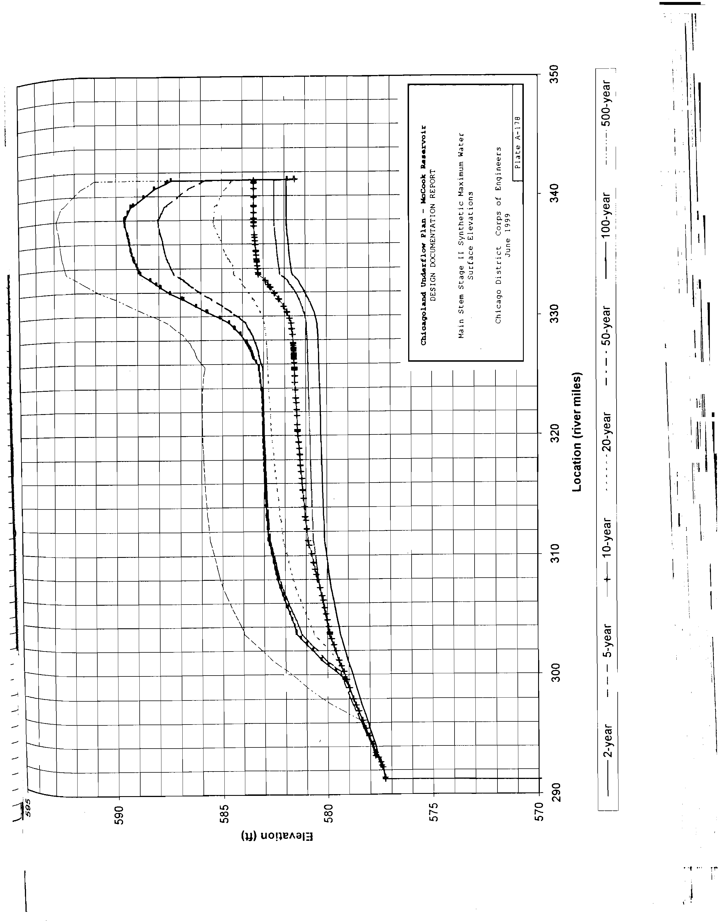
For the conceptual design of the new UV facilities the water surface elevation of +9.0 CCD will be
utilized in order to ensure the new facilities can operate during the 100-year flood. The 100-year
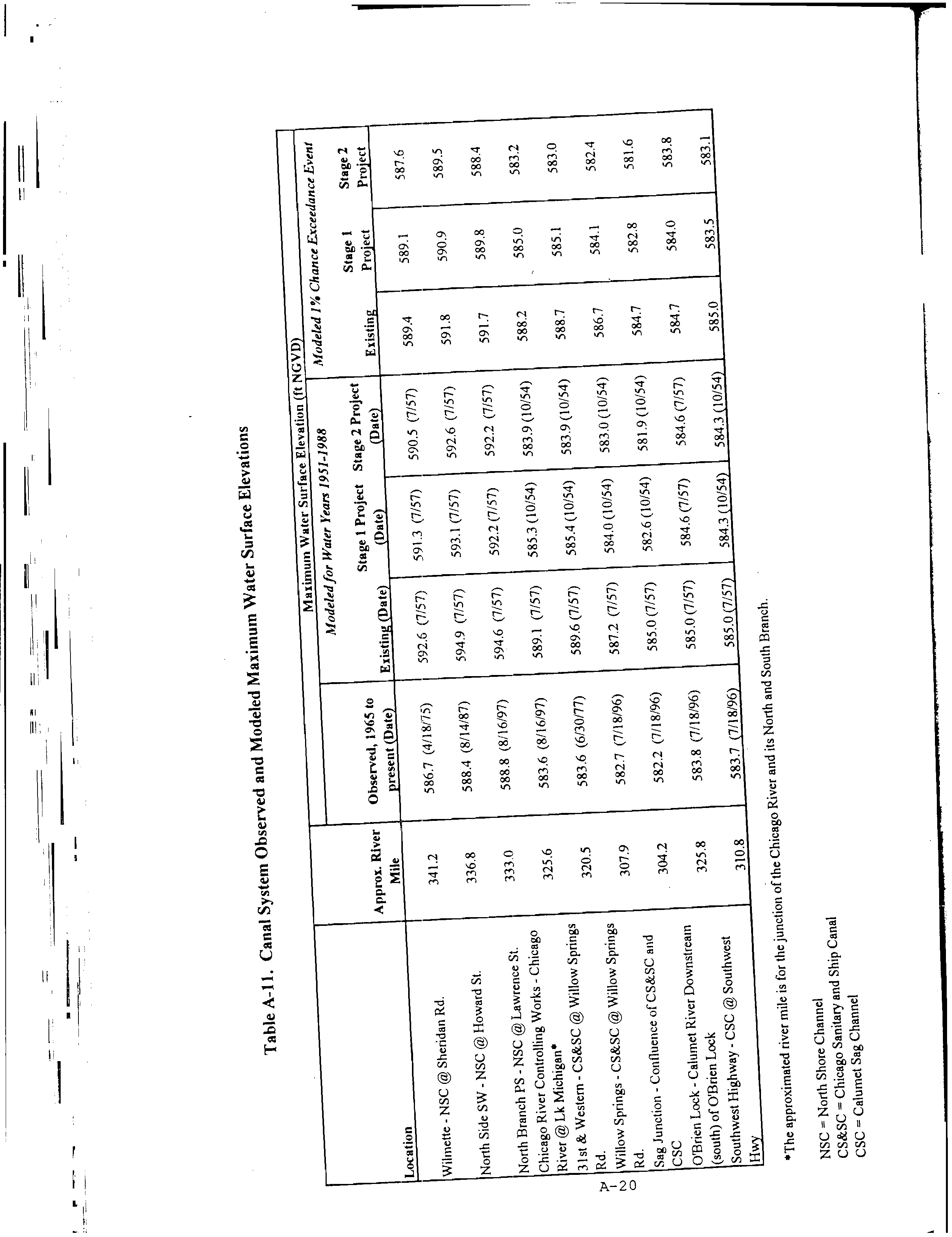
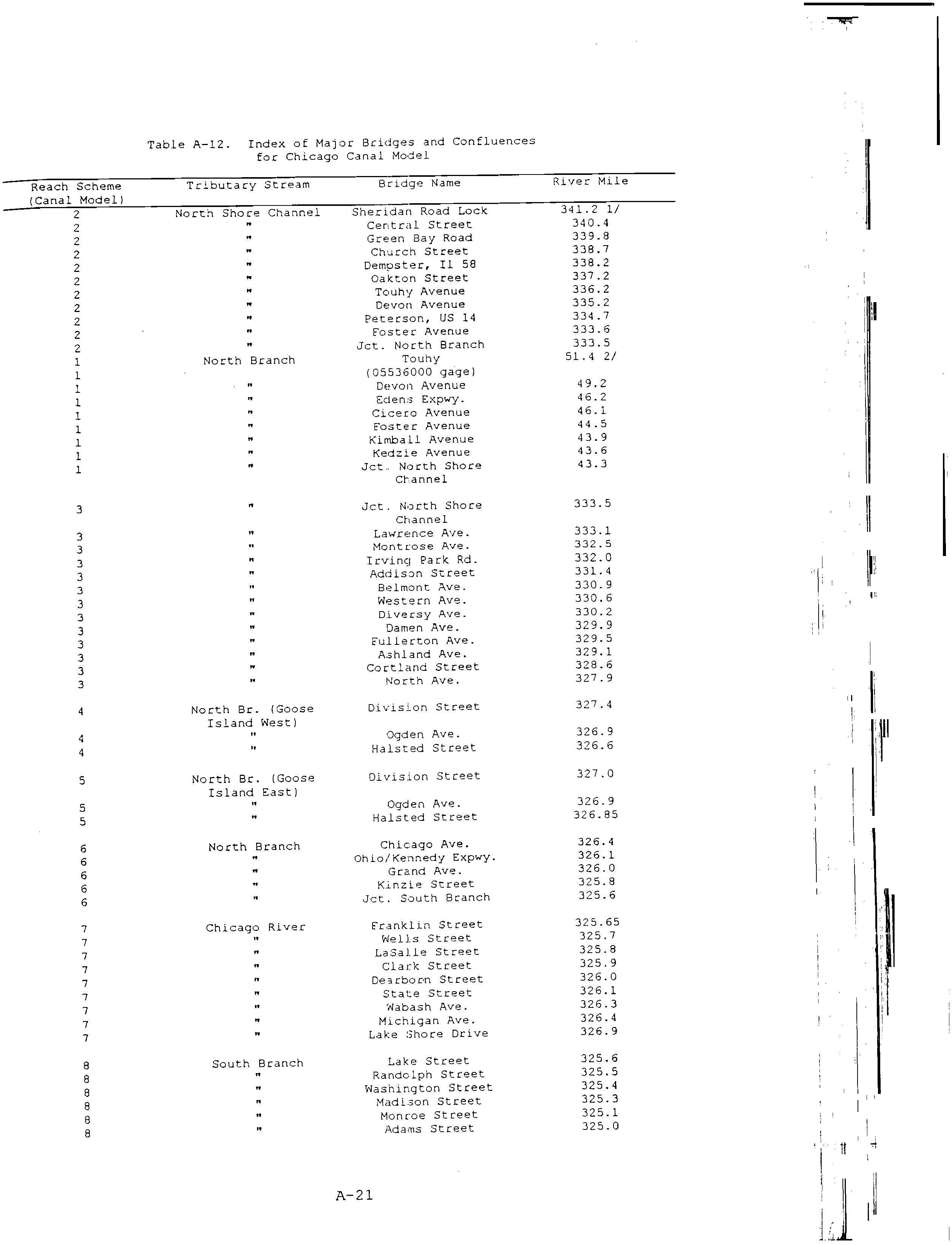
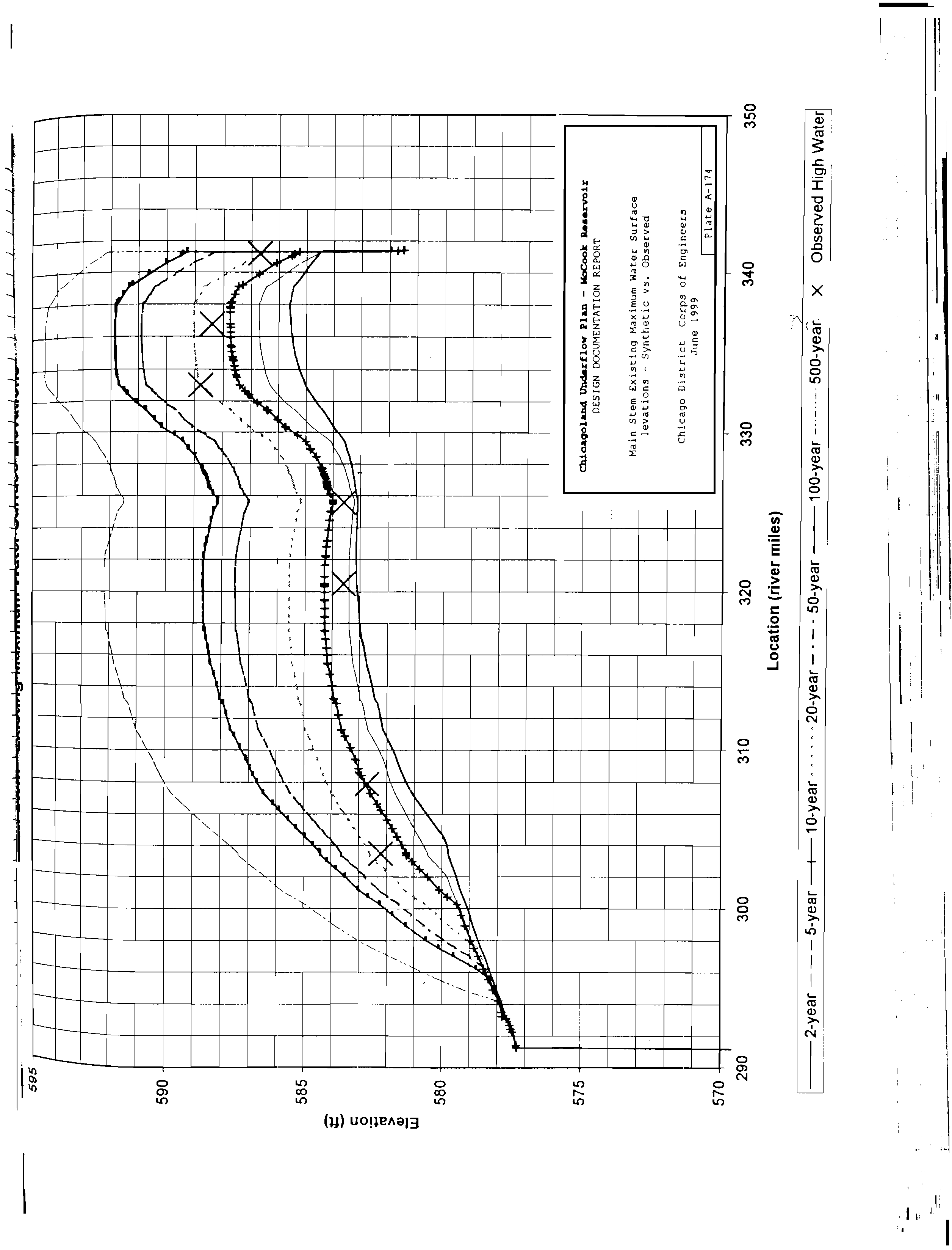
flood elevation for the Sanitary and Ship Canal has been calculated using the USACE’s Chicago
Underflow Plan (CUP) Design Report. The CUP report used observed high water levels to model
the predicted high water levels throughout the Chicago Area Waterways at each of the
construction phases. Appendix A provides select pages from this report.
2.3
Assumptions
Due to the preliminary nature of the selected site plan, assumptions were made in the
development of the hydraulic model. These assumptions are as follows:
1.
SWRP drawings obtained from MWRDGC are on the Chicago City Datum (CCD) or
the National Geodetic Vertical Datum (NGVD). All elevations were converted to CCD
using conversion CCD = NGVD – 579.48.
2.
The CCD has not changed since the plant was originally constructed in the 1920’s.
3.
UV Facilities should be operable at the 100 yr flood event. The estimated 100-yr flood
elevation is +9.00 CCD, as calculated in the Chicago Canal System Model, UNET.
Appendix A provides selected pages from the USACE’s Chicago Underflow Plan
(CUP) Design Report presenting these results. Pre-Stage 1 (Stage 1 of the McCook
Reservoir Construction) values are used since the USACE’s current estimate for
completion of Stage 1 construction in 2020 or later. It should be noted that higher
levels of +10.1 CCD have been predicted for storms greater than the 100-yr storm.
At water levels rise higher than +9.00 CCD (100-yr flood) then flow bypassing would
be necessary to avoid flooding the UV and other facilities.
4.
Post Aeration hydraulics and space planning are not included in this study.
5.
A new plant outfall will be provided to convey disinfected effluent to the Ship and
Sanitary Canal.
6.
Velocity in Disinfection Influent and Effluent Distribution Chambers is zero to allow
adequate flow distribution.
7.
Flow is divided equally between the Batteries A, B, C and D, with each receiving 360
MGD.
8.
Batteries A, B, C and D are all at the same elevation.
9.
The UV process requires approximately 6 ft of submergence, thus the disinfection
channel effluent weir is assumed to be 5.5 ft above invert to ensure a submerged
weir at low flow conditions.
10.
The following modeling equations were used:
a. Pressure Flow – Hazen Williams Equation
b. Open-Channel Flow – Manning’s Equation
c. Flow junctions – Pressure Momentum Analysis.
1
El +3.5 is listed as the maximum water level in the Sanitary and Ship Canal to which the plant would not
flood, based on a maximum design flow rate of 2,000 MGD. This profile appears to be the last official
hydraulic profile conducted for the SWRP.
Electronic Filing - Received, Clerk's Office, Octobr 20, 2008
8
\\Uschg1fp207\p60040695\P60040695\500_Submittals\503_Cost
Study Report\503.1_Draft Report\Final_Cost_Study_Report_091008.doc
11.
Hydraulic coefficients used in developing this model include:
a. Hazen Williams – 110 (concrete)
b. Manning’s
i.
Regular channel – 0.013
ii.
Aerated channel – 0.035
2.4
Results
Table 2.4-1
presents the final water surface elevations (WSE’s) through the plant, including the
Low Lift Pump Station (LLPS) and UV Disinfection Building. The hydraulic profiles show the
estimated WSE’s at the maximum flow of 1,440 MGD. Flow that exceeds 1,440 MGD is diverted
into the TARP system.
Table 2.4-1 – Summary of Proposed WSE including UV Disinfection Facilities
Location
WSE
WSE in Effluent Aerator
10.37
WSE just d/s of Pump Discharge Chamber
5.50
WSE at New Gate Chamber
4.06
WSE in LLPS Influent Conduit
-0.75
WSE in LLPS Wet Well just u/s of curtain wall
-3.25
WSE just D/S of Low Lift PS
13.70
WSE just U/S of Influent gate
13.00
WSE just U/S UV Reactor
12.65
WSE just U/S of Weir Gate
11.89
WSE just D/S of Weir gate
11.42
WSE @ D/S Disinfection Effluent Chamber
9.73
WSE in Sanitary and Ship Canal, Approximate 100 yr flood elevation
9.00
Notes:
All WSE in CCD.
WSE – Water Surface Elevation
D/S – Downstream
U/S – Upstream
Figure 2.4-1
contains the hydraulic profile of the flow path from the new outfall in the Sanitary
and Ship Canal through the new UV disinfection facilities and the available freeboard at the
locations where water surface elevations (WSE’s) were calculated at the peak day flow starting at
the 100-year flood elevation.
2.5
Conclusion
Based on the preliminary hydraulic analysis performed as part of this study, the estimated total
head required to convey flow through the new UV Disinfection facilities and associated structures
is 8.7-ft. The available head downstream of the Pump and Blower Building is 1.95 ft. In order to
maintain flow at the 100-yr flood, a new Low Lift Pump Station is required to lift flow 16.95-ft to
convey flow via gravity through the new UV facilities to the new outfall in the Sanitary and Ship
Canal.
Electronic Filing - Received, Clerk's Office, Octobr 20, 2008
N
Electronic Filing - Received, Clerk's Office, Octobr 20, 2008
10
\\Uschg1fp207\p60040695\P60040695\500_Submittals\503_Cost
Study Report\503.1_Draft Report\Final_Cost_Study_Report_091008.doc
3.0
SWRP DISINFECTION PROCESS
3.1
Introduction
The District has preliminarily selected the medium-pressure high-intensity (MP-HI) UV disinfection
technology for disinfection of final effluent at the SWRP. This section presents the results of
further evaluation of the MP-HI UV disinfection technology per the District’s requirement. In the
following discussion, the basis of design of the MP-HI UV system is presented and a preliminary
basis of design of the UV system to be used at the SWRP is provided. The low-lift pump station’s
basis of design, operation and layout are provided later in this section.
3.2
UV Disinfection System
3.2.1 Background
The Technical Memorandum on the UV Disinfection Technology performed as part of the North
Side Disinfection Cost Study, included in Appendix B, incorporates the following:
x
Information from literature including technical proceedings from the Water Environment
Federation (WEF), Water Environment Research Foundation (WERF), proceedings from
the latest Disinfection conference series undertaken by WEF, American Water Works
Association (AWWA), and International Water Association (IWA). This information
provided the latest updates in the UV disinfection technology.
x
Updated recommendations on the UV system from four manufacturers – Trojan
Technologies, Aquionics, Calgon Carbon, and Severn Trent Services (STS)/Quay.
x
Reference information on experience of UV disinfection at five selected facilities – Racine
WWTP (Racine, WI), R.L. Sutton WRF (Cobb County, GA), Grand Rapids WWTP (Grand
Rapids, MI), Jacksonville WWTP (Buckman, FL), and Valley Creek WWTP (Valley Creek,
AL). A summary of the information collected through the phone survey is provided in
Appendix B, and important inferences from the phone survey are as follows.
1. Fouling due to iron in the effluent has been a problem at the Racine, Sutton, and
Grand Rapids facilities.
Fouling results in lower then expected disinfection
performance, higher operating costs, and higher M&O efforts. The iron in the effluent
at all three plants was primarily from the chemical phosphorus removal using Ferric
Chloride. At Grand Rapids WWTP, the chemical addition is upstream of the
secondary treatment process; staining of sleeves was found only when the chemical
addition was in the secondary clarifiers. At the Sutton WRF, fouling of lamps due to
iron is observed although chemical addition is upstream of secondary process and
sand filters are used upstream of the UV disinfection system. At the Racine WWTP,
fouling may be due to ferric chloride addition and/or due to the additional iron brought
by the ferric sludge from another water treatment plant, although operational controls
are used to prevent both sources from occurring simultaneously.
2. Calcium fouling due to hardness in the source water is not a significant problem
because of the automatic mechanical/chemical cleaning system that dissolves and
wipes away any scales. The lack of calcium hardness was observed in all five plants
including the Racine and Grand Rapids utilities which have Lake Michigan source
water and is attributed to the automatic cleaning system performance.
3. The frequency of cleaning and changing of the cleaning solution is specific to the
utility and would have to be determined only by experience.
4. Labor requirements varied amongst facilities, with some facilities requiring more labor
to handle the fouling caused by iron salt addition.
Electronic Filing - Received, Clerk's Office, Octobr 20, 2008
11
\\Uschg1fp207\p60040695\P60040695\500_Submittals\503_Cost
Study Report\503.1_Draft Report\Final_Cost_Study_Report_091008.doc
5. As long as other processes in the plant are performing as desired, all five facilities
were satisfied with the UV disinfection system because it met their disinfection goals.
In conclusion, the phone survey had revealed that fouling of the quartz sleeves is a concern for
this application, particularly if iron salts are added for phosphorous removal in the future. In
addition, the phone survey results suggest that the manufacturer’s recommended labor
assumptions for routine maintenance including cleaning and inspection of the lamps is too low for
this application. As transmissivity is directly related to lamp fouling, additional lamps and/or more
frequent cleaning may be required in future if iron salts are to be utilized upstream of this
technology.
Using this information and the updated information available from manufacturers, a preliminary
basis of design of the MP-HI UV disinfection system has been developed for disinfection of the
final effluent at the SWRP.
3.2.2
Basis of Design
The MP-HI system involves sending the secondary or tertiary effluent through channels
containing banks of MP-HI UV lamps. Refer to the process drawings included in Volume 2 of this
report. The Trojan UV4000™Plus system is used here to develop the basis of design for the UV
disinfection system. The system consists of a power supply, an electrical system, a reactor, MP-
HI lamps, a mechanical and chemical cleaning system, and a control system. The MP-HI UV
lamps are enclosed in individual quartz sleeves for protection against dirt and breakage. Reactor
chambers (open channels) hold the lamps in a horizontal configuration. The effluent weirs and
level sensors are used to keep the lamps submerged under the effluent water.
This
submergence ensures that the lamps do not overheat, thereby preventing lamp life reduction or
burnout.
The UV system is assumed to operate from March to November each year. During the winter
months, the equipment would sit idle as the flow is bypassed around the LLPS and UV
Disinfection Building. However, due to the size of the facility including twelve reactors and over
4000 lamps, maintenance activities would be conducted every working day from March to
November and periodically during the winter months. It is reasonable to expect that the area
would continue to experience normal weather patterns for the Chicago area including extreme
weather during all four seasons. In order to protect the safety of the M&O staff, ensure
operational and maintenance-related productivity, and protect the UV equipment from adverse
weather common to the Chicago area including high winds, rain, lightning, snow, and extreme
temperatures, the UV system would be enclosed in a building.
3.2.2.1 Influent Characteristics
The water quality characteristics that affect UV transmittance include iron, hardness, suspended
solids, humic materials and organic dyes. These effluent constituents have a tendency to absorb
UV light and thus impact the disinfection process. The UV transmittance generally needs to be
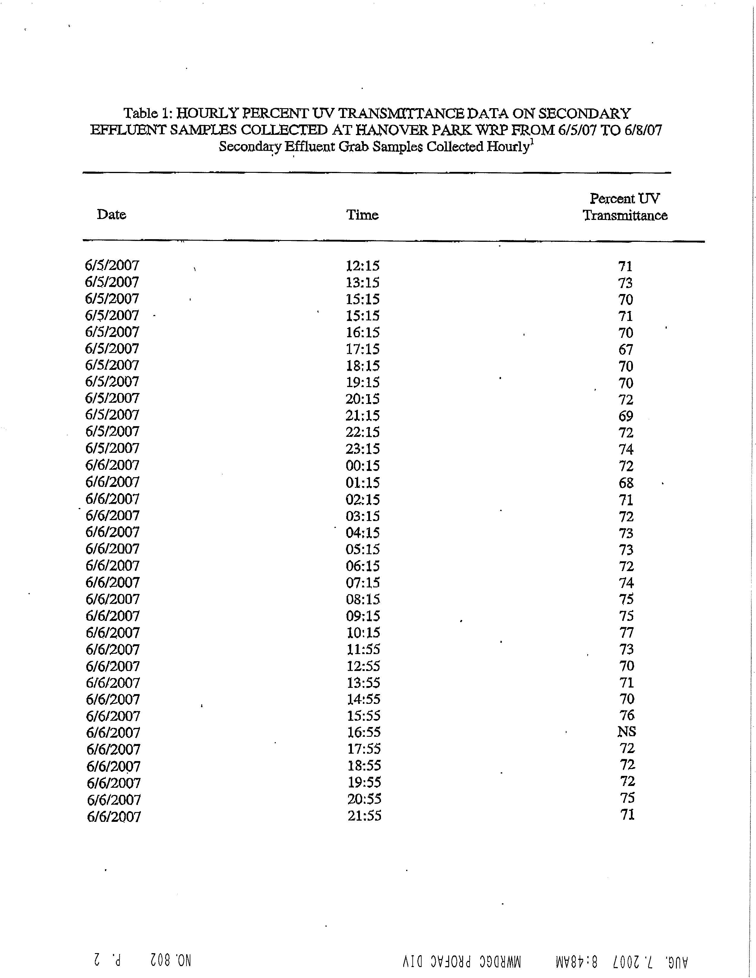
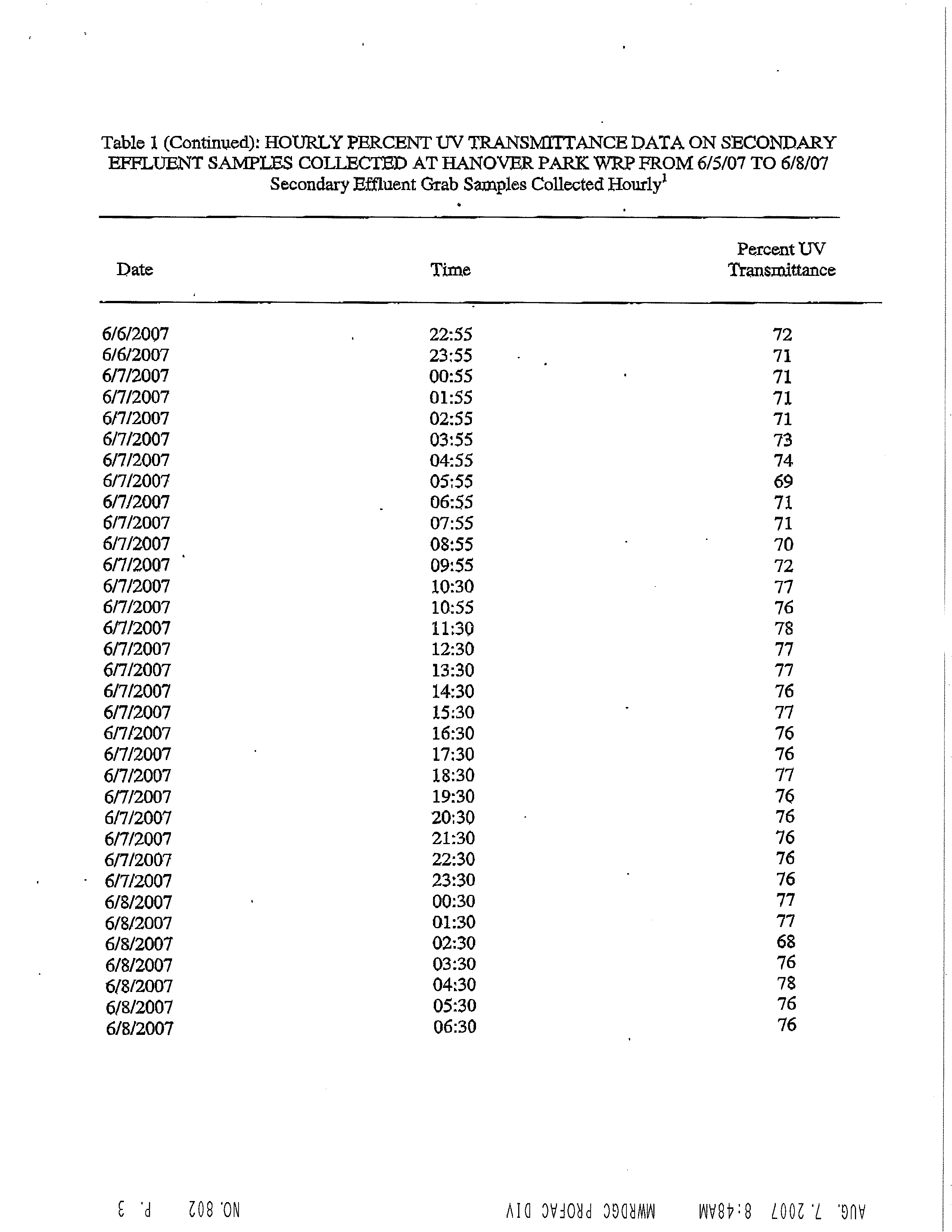
above 65% for effective disinfection. The water quality testing done at the North Side WRP and
Calumet WRP as part of the UV disinfection technology trials conducted by the District during
2006-2007 showed an average transmittance above this minimum value. Although testing was
not done at Stickney WRP the characteristics are likely to be very similar. Refer to Appendix B
for more information regarding the influent characteristic testing. The total suspended solids limit
is projected to be 15 mg/L for the purposes of sizing the UV system.
3.2.2.2 Reactor Configuration and Hydraulics
An open channel is used as a reactor. Each channel has one reactor with two banks each. Each
bank includes stainless steel UV modules with the MP-HI lamps mounted on them and arranged
in a linear configuration to increase intensity along the linear axis by avoiding UV emission losses
due to self absorption, reflection or refraction that can occur if a UV lamp were twisted into loops
or spirals. The lamps are positioned horizontally and parallel to the flow.
Electronic Filing - Received, Clerk's Office, Octobr 20, 2008
12
\\Uschg1fp207\p60040695\P60040695\500_Submittals\503_Cost
Study Report\503.1_Draft Report\Final_Cost_Study_Report_091008.doc
The optimum hydraulic scenario for this system involves turbulent flow with mixing while
minimizing head loss. Reactor design, including inlet and outlet flow distribution is done so that
the unit operates close to a plug flow. Inlet conditions are designed to distribute the flow and
equalize velocities. Sufficient length is provided in the channel upstream of the reactor to allow
equalization of the flow. A motorized weir gate is provided downstream of each reactor to control
the water level at a constant level with little fluctuation within the UV disinfection reactor.
3.2.2.3 Lamps and UV Intensity Control
The MP-HI lamps produce polychromatic radiation, which is concentrated at select peaks
throughout the germicidal wavelength region. The IEPA requires a minimum UV dose of 40 mW-
s/cm
2
which was considered during the design of the UV system. It may be possible to document
a lower required dose to the regulating body (IEPA) during design development, but lacking such
data, this study does not deviate from the required minimum dose.
Each lamp is enclosed in a quartz sleeve because quartz effectively protects the lamps while
minimizing any UV transmission losses. Electronic ballast for each lamp is used to control the
power to the lamp. If the UV dose is to be reduced, the variable output electronic ballast
regulates the power to the lamp from 100% to 30%. Entire banks can also be turned off if there is
no flow. This allows dose-pacing based on the secondary or tertiary effluent flow and quality,
which helps save power and lamp life and hence reduce costs.
3.2.2.4 Lamp Fouling and Cleaning
The MP-HI lamps operate at a temperature range of 600 to 900 degree C. These warm
temperatures promote fouling on the surface of the quartz sleeves when the lamps are placed
directly within the wastewater stream. Iron is the most abundant metal in these scales along with
other mineral salts and oil, grease, suspended solids deposits, and biofilms. If no tertiary
treatment is provided, physical debris may contribute to fouling as well.
Since lamp fouling significantly reduces the effectiveness of UV disinfection by blocking the UV
rays, calculation of the UV dose incorporates a term called the “fouling factor”, which allows the
designer to estimate the effects of fouling on performance of the disinfection process. To combat
fouling, a chemical and mechanical cleaning system is proposed for the MP-HI UV disinfection
system. The latest technology uses a system of mechanical wipers and sleeves containing
cleaning chemicals surrounding the lamp. The cleaning solution contains some acidic solution
that prevents fouling. This cleaning system can be programmed to clean at a set frequency
without the need for disrupting the disinfection process. The cleaning solution needs to be
replaced periodically depending on the type of solution used and characteristics of the effluent
water quality. Similar facilities using Lake Michigan as source water have found that changing
the cleaning solution on a monthly basis is required for adequate performance.
Due to the mechanical and chemical features of the Trojan automatic cleaning system, the IEPA
accepts the default value of 100% for the fouling factor in the UV
dis
software package (dosage
modeling software) for sizing the equipment. Based on the phone survey results that indicated a
higher potential for fouling in the event of Lake Michigan source water with ferric salt addition, the
District has elected to incorporate a safety factor of 10% by using a fouling factor of 90%.
3.2.3 Process Control
An automated process control must be provided to facilitate online pacing of the UV dose to
prevent overdosing that wastes electricity and to avoid under-dosing that would not meet the
disinfection regulatory requirements and goals. The process control should also allow the dose-
pacing to be interfaced with the plant’s overall supervisory control and data acquisition (SCADA)
system. The flow, lamp output, and water conditions are measured in pacing of the dose, and an
algorithm is developed based on long-term measurements to predict necessary system
adjustments, maintenance, and component replacements.
Electronic Filing - Received, Clerk's Office, Octobr 20, 2008
13
\\Uschg1fp207\p60040695\P60040695\500_Submittals\503_Cost
Study Report\503.1_Draft Report\Final_Cost_Study_Report_091008.doc
Programmable logic control (PLC) technology must be used for dose pacing in the MP-HI UV
disinfection system. The PLC interacts with the ballasts, sensors, and online monitoring
technology for each disinfection unit. The PLC then interacts with the plant’s overall control
system to allow remote monitoring and adjustment of the system. The PLC should be supplied
by the manufacturer of the unit.
3.2.4 Safety
The high voltage power supplies for the MP-HI UV disinfection system may pose an issue as the
lamps are submerged in the water most of the time and compliance with electrical safety codes is
required. In addition, UV light poses a risk to personnel and can cause damage to skin or eyes
upon exposure. Submerging a lamp in water, even if it is just a few inches below the surface,
greatly reduces the intensity. During operation the system should be covered by hatches and
should be designed to ensure constant water levels to minimize the risk of UV exposure.
3.2.5 Proposed Design Criteria for UV Disinfection Equipment
Based on a review of the information provided by the UV equipment manufacturers and the
experience of five other facilities (Appendix B), it is observed that Trojan Technologies provides a
widely-used low-maintenance solution for final effluent disinfection. The design of the MP-HI UV
disinfection system for the Stickney WRP is based on the Trojan UV4000™Plus equipment
provided by Trojan Technologies. The basis of design is given in
Table 3.2-1
.
Table 3.2-1 – Design Parameters for UV Disinfection Unit at SWRP
Parameter
Design Value
Capacity and Water Quality
Design flow, MGD
1,440
Average flow, MGD
1,250
Maximum TSS
a
, mg/L
15
Pre-Disinfection Effluent Fecal Coliform Count
b
, cfu/100 mL,
maximum (Assumed)
25,000
Post-Disinfection Effluent Fecal Coliform Count Target
c
, cfu/100 mL
400
Effluent Hardness
d
, mg/L as CaCO
3
270
Dosage
UV transmittance, minimum, %
65
UV intensity
e
, W/lamp
4,000
Lamp Life, hours
5,000
Fouling factor, %
90
Lamp aging factor, %
89
UV dose, mW-s/cm
2
40
Physical Characteristics
Channel dimensions, WxD
106” x 172”
Number of channels
12 (11 plus 1 standby)
Number of reactors per channel
1
Number of banks per reactor
2
Number of modules per bank
7
Number of lamps per module
24
Total number of lamps
4,032
Total power requirement, kW
11,827
Average power requirement, kW
9,225
Hydraulics
Headloss, UV reactor only
9”
Velocity in each channel, V, ft/s
1.87
Liqui
a
b
d
AMonth
l
nn
ev
u
e
al
l
l
cont
y
avpereragmit
ro
e
l
li
in
mit
channel
12 mg/L
c
d
FuturMean e
valrequuire
ement (monthly geom
e
100et%
ric
intavenseragity
e)at
100
Mot
hours
ori
o
zed
f lam
W
p us
eir
e
Gate
Electronic Filing - Received, Clerk's Office, Octobr 20, 2008
14
\\Uschg1fp207\p60040695\P60040695\500_Submittals\503_Cost
Study Report\503.1_Draft Report\Final_Cost_Study_Report_091008.doc
The above design criteria are assumed based on available information and the current state of
ultraviolet disinfection technology. A more extensive technology evaluation should be conducted
prior to final design of the facility. Due to the extraordinary scale of this facility, CTE recommends
the District undertake the following design process for selection and design of the UV disinfection
equipment if final design is initiated:
1. Request and evaluate independent, full-scale validation data (also known as
biodosimetry data) from manufacturers of candidate disinfection systems for similarly
sized units or the largest size for which the manufacturer has data available. This
evaluation would provide an initial level-of-confidence that the candidate systems can
achieve the target disinfection levels. Data should be from systems using the same bulb,
ballast, and control technology as proposed for the full-scale system. Candidate systems
should include both medium pressure, high intensity as well as appropriate low pressure,
high intensity systems,
2. Conduct a collimated beam testing program. This program would use site specific
effluent and bacteria to determine the sensitivity of the site specific bacteria and
pathogens to UV disinfection. The data would be used to size the UV lamps and
reactors.
3. Increase frequency of UV transmittance testing at each plant to at least once per day for
a period of one year or more to collect data on seasonal variability, daily variability,
diurnal variability, and to capture the frequency of events that might reduce transmissivity
such as wet weather and infrequent industrial discharges.
4. Conduct a more detailed life cycle cost analysis of the candidate disinfection systems
based on the data collected during steps 1 through 3 above.
5. Construct a pilot testing facility (approximately 20 MGD, subject to change) designed to
match lamp spacing, velocity profile and other design parameters of the proposed full
scale units. The pilot testing facility would be used to determine:
a. Appropriate control sequences and optimization for the UV disinfection equipment,
including appropriate sensing equipment to allow advanced power management.
b. In-situ disinfection performance including fouling rates of the lamps with and without
ferric salt addition.
c. Design life of lamps and other UV system parts.
d. Actual M&O requirements in terms of labor and consumables as well as space
requirements to complete required maintenance activities.
e. Performance of alternate equipment manufacturers, if alternates are available at the
time of piloting.
f. Accuracy of life cycle cost analysis prior to final design of the full-scale system.
6. Conduct post-construction full-scale validation testing (biodosimetry testing) to confirm
performance and determine operating parameters.
Using a program as described above, it may be possible to demonstrate the effective UV
dosages to the regulators and optimize the equipment sizing criteria. For this study, reduction in
the Illinois requirements for UV system sizing is not assumed based on the lack of data similar to
that described above.
Electronic Filing - Received, Clerk's Office, Octobr 20, 2008
15
\\Uschg1fp207\p60040695\P60040695\500_Submittals\503_Cost
Study Report\503.1_Draft Report\Final_Cost_Study_Report_091008.doc
Budgetary costs for a 20 MGD pilot facility were included in the costs for implementation of the
UV Disinfection Facilities at North Side Water Reclamation Plant, and as such are not included in
this study.
3.3
Low Lift Pump Station
Based on the analysis of hydraulics of the proposed improvements described in Section 2 above,
it is estimated that the low lift pumps would be required to raise the water approximately 23.5 feet
(including static and friction losses) to the UV disinfection system influent, including estimated
head to allow flow through the UV system. The static head equates to the difference in the
estimated water surface elevation between the wet well and the discharge conduit plus an
additional 2-ft of head added as a conservative factor to accommodate additional losses that may
be identified during final design.
3.3.1
Basis of Design
Table 3.3-1
provides a summary of the basis of design for the Low Lift Pump Station.
Table 3.3-1 – Low Lift Pump Station Basis of Design
Peak Flow, MGD
1,440
Average Flow, MGD
1,250
Pumps
Type
A x ial Flow
Number
8 total (N+1+1)
Pumping Rates, gpm/pump
166,670
Static Head, ft
16.95
Dynamic Head, (inc. station losses), ft.
4.5
Total Dynamic Head, ft
(1)
23.5
Motor, hp
(2)
1,500
Submergence, minimum, ft
18.5
Peak Power Demand, kW
5,282
Average Power Demand, kW
4,455
Wet Well
Length, ft.
86
Width, ft.
114
(1) The static head equates to the difference in the estimated water surface elevation between the wet well and
the discharge conduit plus and additional 2-ft of head added as a conservative factor to accommodate
additional losses that may be identified during final design.
(2) A 1,350 hp motor could be provided, however this is a non-standard size and only standard motor sizes
were assumed for this conceptual study.
3.3.2 Pump Type
Initially, the Low Lift Pump Station would lift 1,440 MGD a total of 16.95 feet with a Total Dynamic
Head (TDH) of 23.5 feet. If tertiary filtration is constructed in the future, the TDH would most
likely increase but the flow would remain the same. Screw pumps will not easily accommodate
this change in head without significant structural modifications to the pump station. However
axial pumps can be modified for future head conditions. Structural modifications to the pump
station to accommodate these changes, if required, should be minimal. Therefore, axial flow,
propeller type pumps are recommended.
Vertical axial flow pump have been assumed here, but other configurations (including inclined or
horizontal) could be considered in the future. In addition, because the total dynamic head
required for the short and long term conditions is approaching the limit of axial flow pumps of this
size, mixed flow pumps (e.g. vertical turbine pumps) may also be considered though the general
Electronic Filing - Received, Clerk's Office, Octobr 20, 2008
16
\\Uschg1fp207\p60040695\P60040695\500_Submittals\503_Cost
Study Report\503.1_Draft Report\Final_Cost_Study_Report_091008.doc
space requirements and layouts would be similar to those assumed for this study. Final selection
of pump type would be completed during preliminary design.
3.3.3 Proposed Operational Description
The pump station would have a total of eight pumps, with six duty pumps, one standby and one
out of service (N+1+1). Five pumps would be driven by constant speed motors, three would be
variable speed driven. In order to provide operational flexibility, the pump station would be
divided into two wet wells, each containing four pumps. Normal wet well levels would be
approximately -3.25 feet Chicago City Datum (CCD). Design average flow (1,250 MGD) could be
handled by four constant speed and two variable speed pumps, leaving two pumps on standby.
Peak flow (1,440 MGD) could be handled by six pumps, leaving two on standby. Minimum flow
(365 MGD) would be handled by two variable speed pumps. Typically, at least one variable
speed pump would operate at all times, to handle fluctuations in flow.
Table 3.3-2
illustrates an
example of pump operation at minimum, design average flow, and peak flow:
Table 3.3-2 – Examples of Pump Operation
Flow, MGD
Pump Drive
Type
Pump
Flow, gpm
TDH, ft Pump Eff.
Power Demand,
kW
Variable speed
130,358
21.7
365 (5-year
84%
637
m in i mu m)
1
Variable speed
130,358
21.7
84%
637
Constant speed
166,667
23.5
88%
880
Constant speed
166,667
23.5
88%
880
Constant speed
166,667
23.5
88%
880
Constant speed
166,667
23.5
88%
880
Variable speed
100,694
20.6
84%
467
1,250 (Design
Average)
Variable speed
100,694
20.6
84%
467
Constant speed
166,667
23.5
88%
880
Constant speed
166,667
23.5
88%
880
Constant speed
166,667
23.5
88%
880
Constant speed
166,667
23.5
88%
880
Constant speed
166,667
23.5
88%
880
1,440 (Peak)
Variable speed
166,667
23.5
88%
880
1
5-year minimum based on SWRP historical data.
In order to eliminate vortices, pumps require a minimum submergence as a function of pump
suction bell diameter. For this flow condition, a 120-inch suction bell is required, which requires a
minimum submergence of 16-feet. Submergence requirements should be verified by the pump
manufacturer during final design.
Level sensors in the wet well would relay a signal to turn pumps on and off. The level control
would be automatic under normal conditions, with manual override possible. Other control inputs
that need to be monitored include discharge pipe pressure, flap gate position, and motor alarms.
3.3.4 Proposed Layout
Figure 3.3-1
below, shows the proposed flow diagram for the new UV disinfection facilities.
During the disinfection period the flow would be diverted through the new facilities just upstream
of the existing outfall.
Electronic Filing - Received, Clerk's Office, Octobr 20, 2008
17
\\Uschg1fp207\p60040695\P60040695\500_Submittals\503_Cost
Study Report\503.1_Draft Report\Final_Cost_Study_Report_091008.doc
Figure 3.3-1 - Proposed UV Disinfection Flow Diagram
Refer to Sheet C-101 for a proposed site layout of the LLPS and UV Disinfection Building. The
space available for the construction of the new UV disinfection facilities is constrained by the lack
of space adjacent to the existing outfall. The LLPS would be located in the available space in the
southwest area of the site. A new gate structure would direct the flow by gravity approximately
1,800-ft from a junction south of the Pump Discharge Chamber to the new LLPS. Due to the
existing Northwest Interceptor, this new conduit will require an inverted siphon to pass
underneath the interceptor, as shown in .
Referencing Sheet P-301, flow would enter the pump station at the south end of the wet well,
where it would be directed perpendicularly to a wet well via six (6) 120-inch square slide gates.
Pumps are located at the north end of the pump station. An ideal pump intake approach per
Hydraulic Institute standards was not possible due to the prohibitively long approach length
required.
To accommodate the non-ideal pump intake approach, design features, which have been shown
to be effective in other installations, were incorporated in this design in order to meet HI
standards. For example, perforated plates, curtain walls and floor and back wall splitters have
been incorporated into the conceptual design. (See Volume 2 for a plan and section of the
proposed layout). Sizing and details of these types of features are normally determined by
physical scale modeling during detailed design. Furthermore, based on the total flow and flow
per pump, the Hydraulic Institute recommends physical scale modeling.
4.0
SWRP CIVIL
Due to constraints of the site related to the proposed location of the disinfection facilities, several
significant civil improvements would be required. Those improvements include the following:
1. Construction of new roadways to access the new facilities and future tertiary filters
2. Construction of a new gate structure and effluent conduits connecting the LLPS, UV
Disinfection Building as well as a new plant outfall.
3. Construction of associated utilities including stormwater collection, city water, plant water,
plant drain, electrical duct bank, and steam/condensate return.
E x isting
Plant
LLPS
UV
Facilities
Future
Tertiary
Filters
New
Outfall
E x isting
Outfall
Q=1,440
MGD
(Winter Operation)
Junction
Chamber
Electronic Filing - Received, Clerk's Office, Octobr 20, 2008
18
\\Uschg1fp207\p60040695\P60040695\500_Submittals\503_Cost
Study Report\503.1_Draft Report\Final_Cost_Study_Report_091008.doc
4.1
Basis of Design
Refer to the Drawings C-101, C102 and C103 in Volume 2 of this report for a layout of the
proposed facilities on the site. The basis of design of each of the civil related improvements is
presented below.
4.1.1 Roadways and Other Site Improvements
Proposed roadways associated with the UV Disinfection Facilities are intended to provide access
to the structures and site for normal operations as well as allow access to heavy construction
vehicles and delivery vehicles. The roadway would be constructed in accordance with District
guidelines. It would be designed for AASHTO H-20 loading with an assumed reinforced Portland
cement concrete thickness of 12-inches. Curb and gutter (standard 12-inch wide gutter with 6-
inch curb) would be provided to facilitate maintenance and stormwater collection.
4.1.2
Junction Chamber/Effluent Conduits
Final effluent conduits connecting the various facilities associated with the UV Disinfection
Facilities would be constructed along with the primary facilities. All conduits are rectangular and
are sized as follows:
x
17.5-ft x 15.75-ft for the influent to the LLPS,
x
16-ft x 20-ft for the influent conduit to the UV facilities
x
20-ft x 20-ft for the final effluent conduit.
The difference in conduit sizing reflects different hydraulic head loss requirements between
facilities. All effluent conduits would be cast-in-place concrete construction designed for closed
conduit flow. Due to the comparatively low weight of the conduits and water contained therein
compared to the soil excavated, no deep foundations are anticipated at this time. Where
possible, common wall construction with adjacent structures is assumed.
It should be noted that the LLPS Discharge Conduit would initially be designed for open channel
flow. However, in the future, this conduit would be under pressure when the LLPS pumps are
replaced to allow pumping to the tertiary filtration facility when it is constructed. As such, this
conduit would be designed for pressure of approximately 15-feet of head above the top slab.
Junction Chamber #1
Referencing Sheet S-101, Junction Chamber #1 connects the new LLPS influent conduit to the
existing plant outfall conduit. This structure would be designed to convey flow through the
disinfection facilities when required or bypass the facilities to the existing plant outfall when not
required. Motorized, fabricated stainless steel sluice gates on the upstream ends of the new
LLPS and existing outfall conduits would be provided. No aboveground structures would be
associated with the junction chamber, though its top would be 6-inches above grade. Guard rails
and/or concrete bollards would prevent traffic over the junction chamber to protect the motor
actuator.
During the disinfection period (March to November), the gate on the upstream of the existing
outfall conduit would be normally closed to force flow from the existing site through the open gate
on the LLPS influent conduit into the LLPS wet well. During the winter period (November to
April), the gate operation would be reversed to allow bypass of existing site flow around the
disinfection facilities. An access hatch would be provided to allow access to the structure.
Construction of Junction Chamber #1 would be cast-in-place concrete. The foundations for the
chamber will be cast in place on undisturbed soil with at least 3 ksf allowable bearing capacity.
The base of the structure would form the connection to the existing plant outfall conduit.
Electronic Filing - Received, Clerk's Office, Octobr 20, 2008
19
\\Uschg1fp207\p60040695\P60040695\500_Submittals\503_Cost
Study Report\503.1_Draft Report\Final_Cost_Study_Report_091008.doc
Underpinning of the existing and new conduits would be completed to prevent unexpected strain
on the structures. The gate structure base would be constructed around the existing conduit.
The final connection would be made “in the wet” by removing the top of the existing concrete and
inserting a pre-constructed bulkhead along one side of the conduit. A water tight seal around the
bulkhead is not likely to be possible and dewatering pumping is assumed necessary. It is
assumed that plant flow would be controlled to maintain a narrow range of flows during this
construction by diverting flows in excess of dry weather flow to TARP temporarily. The final
connection would be made by sawcutting the opening and repairing the exposed surfaces before
removal of the bulkhead.
Following the final completion of the connection, a second and third full pipe diameter bulkhead
would be constructed upstream and downstream of the proposed gate in the existing plant outfall
conduit to allow its installation. Plant flow would be diverted through the UV Disinfection Facilities
during this work. Underwater construction techniques would be required to make the insertion
and sealing of the bulkheads. Following installation of the gate, the bulkheads would be removed
and the gate structure would be completed to grade.
Costs for the gate structures and special connections have been included in the opinion of
probable construction cost included in Appendix F.
4.1.3
Site Utilities
Site utilities would be demolished, rerouted, and constructed to support the new facilities. The
following utilities would be demolished or rerouted as shown on Sheet C-102:
1. Abandoned Site Utility – Demolished
2. Abandoned Railroad and Rail Yard – Demolished
3. Temporarily reroute active railroad tracks for construction of effluent conduit and outfall
The following site utilities would be added to support various functions for the new LLPS and UV
Building:
1. City Potable Water – New potable water extended to the LLPS and UV Disinfection
Building along the south side of the Preliminary Settling Tanks from the existing service
adjacent to the south east corner of Preliminary Settling Tanks.
2. Non-Potable Water – Routed from the existing piping south of the Pump and Blower
House to the LLPS and UV Building for wash down use.
3. Plant Drain – New sanitary plant drain installed from the LLPS and UV Building to a new
connection at the existing Salt Creek Interceptor.
4. Stormwater Collection – New storm drains collect stormwater runoff from the new
buildings and roadway and routed to aforementioned new plant drain.
5. Steam and Condensate – Constructed from existing services east of the Sludge Disposal
Building to the LLPS and UV Disinfection Buildings.
4.1.5 Geotechnical Information
The project team has reviewed the Draft Geotechnical Design Report completed as part of the
New Preliminary Treatment Facilities for Stickney and Calumet WRPs. This report reviewed
boring logs and provided a preliminary opinion on suitable foundation type for the proposed
preliminary treatment facilities which were located just north of the proposed UV disinfection
facilities and LLPS. A copy of the report is provided in Appendix E.
Electronic Filing - Received, Clerk's Office, Octobr 20, 2008
20
\\Uschg1fp207\p60040695\P60040695\500_Submittals\503_Cost
Study Report\503.1_Draft Report\Final_Cost_Study_Report_091008.doc
The proposed site is within the former Ash Lagoons and the report indicates that in general, fill
and topsoil are encountered near the ground surface. At Boring ST-13 in the area of the
proposed LLPS, a buried 2-ft layer of top soil was encountered at a depth of 4-ft which was
underlain by 14-ft layer of soft to stiff wet clay. Native soils encountered beneath the fill materials
and organic materials generally consisted of stiff to very hard silty clay soils. Lenses of silt and
clayey silt are encountered before reaching apparent bedrock at depths of 55-60 ft.
The proposed structures would be located 15 to 40-ft below the existing grade. The base of the
structures would be located in the stiff silty clay soils. As a conceptual design, a mat foundation
with rock anchors to resist the groundwater uplift force for the LLPS and the UV Building is
provided. Based on the analysis performed for the Draft Geotechnical Design Report, it is
anticipated that settlement would be approximately 1-inch.
A detailed subsurface investigation is recommended to characterize the stiff, silty clay layer and
underlying soil layers in the vicinity of the proposed structures. Both strength and consolidation
properties of these soils should be determined by field and laboratory testing. These data would
be necessary for the final selection and design of the foundation system.
5.0
SWRP STRUCTURAL AND ARCHITECTURAL
5.1
Introduction
The objective of this Section is to document the design criteria for the structural, architectural
components of this project, including recommendations, allowable stresses, and loadings that
would be used in designing the new project structures and modifying existing structures. Refer to
the structural and architectural drawings in Volume 2 of this report.
5.1.1 Codes and Specifications
The following codes would be used in addition to the general design standards listed in Section
1.2:
x
The International Building Code 2003 (IBC) – Village of Skokie
x
The International Fire Code 2003 (IFC)
x
NPFA 101, Life Safety Code, 1997 Edition
x
OSHA, United States Department of Labor, Occupational Safety and Health
Administration, Latest Edition
x
Building Code Requirements for Structural Concrete, (ACI 318-02) and Commentary,
(ACI 318R-02).
x
Code Requirements for Environmental Engineering Concrete Structures, ACI 350-01)
and Commentary (ACI 350R-01).
x
Seismic Design of Liquid Containing Concrete Structures, (ACI 350.3-01), and
Commentary, (ACI 350.3R-01).
x
ACI “Manual of Concrete Practice”, 2005, American Concrete Institute, Detroit, MI.
x
ACI Committee 315, “Details and Detailing of Concrete Reinforcement, ACI 315-99.
x
Specification for Structural Steel Buildings – Allowable Stress Design and Plastic Design,
Ninth Edition, June 1, 1989
x
Manual of Steel Construction Allowable Stress Design, Ninth Edition, 1989
x
Building Code Requirements for Masonry Structures and Commentary, ACI 530-02,
ASCE 5-02/TMS 402-02 and Specification for Masonry Structures and Commentary, ACI
530.1-02/ASCE 6-02/TMS602-02.
x
American Society of Civil Engineers, Minimum Design Loads for Buildings and Other
Structures, ASCE 7-02.
Electronic Filing - Received, Clerk's Office, Octobr 20, 2008
21
\\Uschg1fp207\p60040695\P60040695\500_Submittals\503_Cost
Study Report\503.1_Draft Report\Final_Cost_Study_Report_091008.doc
x
American Association of State Highway and Transportation Officials, AASHTO, Standard
Specifications for Highway Bridges, Seventeenth Edition, 2002
x
Soil Boring Logs in Contract 78-020-CP For Secondary Treatment Facilities at the North
Side Sewage Treatment Works.
x
The Illinois Accessibility Code 2004.
x
The Metropolitan Water Reclamation District of Greater Chicago (MWRDGC) “Standard
Specifications”.
x
The MWRDGC Design and Construction Manual, “Engineering Standards”.
x
United States Naval Facilities Command (NAVFAC), September 1986, “Design Manual
7.02, Foundations and Earth Structures”.
x
CFR 29 Parts 1900-1910.999 and Part 1926, OSHA
x
American Society for Testing Materials (ASTM) Standards.
x
American Welding Society, ANSI/AWS D1.1-98, “Structural Welding Code – Steel”
5.1.2 Loads
The following design loads would be used for the proposed structures:
Tanks, Channels and Structures below Grade:
x
Hydrostatic liquid pressure-operating water level/flood water level – 62.4 psf.
x
Lateral earth pressure for active, at-rest and passive conditions – Per Geotechnical
Report (lateral load due to surcharge loading of H-20 truck would be added).
x
Surcharge Load – 3 feet of soil.
x
Frost depth – Minimum 3’-6” below finished grade.
x
Design high ground water table elevations. All new structures would be checked for
buoyancy for the case of high ground water table at finished grade and dead load of the
structure only and is described in Part 6.1.4 below.
Roof Slab at or below Grade:
x
DL:
Weight of concrete slabs
x
SDL: Backfill and other superimposed dead loads including underhung ancillary
equipment and piping
x
LL:
The equivalent of 3 feet of soil or H-20 truck loading whichever governs
Buildings and Miscellaneous Structures:
x
Loadings for design of the building would be obtained from appropriate codes; however,
certain minimum loads would be used as shown in Part 6.1.2.3 below.
Minimum Uniform Live Loads:
x
Checkered Plate:
150 psf
x
Grating:
100 psf
x
Stairs and catwalks:
100 psf
x
Electrical control rooms:
250 psf - Estimate support area and equipment weights
and assume loads applied anywhere in area
x
Heavy Equipment rooms:
300 psf
x
Dismantling and storage
x
Storage areas:
150 psf - Determine reasonable stacking height and type
of stored material
x
Shop floors:
150 psf
x
Garage floors:
150 psi
Electronic Filing - Received, Clerk's Office, Octobr 20, 2008
22
\\Uschg1fp207\p60040695\P60040695\500_Submittals\503_Cost
Study Report\503.1_Draft Report\Final_Cost_Study_Report_091008.doc
x
Truck wheel loads per AASHTO and as appropriate
x
All other:
150 psf
x
Fastest mile wind speed (mph):
75 mph
x
Snow (minimum):
30 psf - Snow drift loads would be checked
where applicable in addition to all top supported and under hung ancillary equipment and
piping
x
Underhung piping and equipment where indicated, in addition to the required:
50 psf minimum roof live load
x
Equipment live load plus 50 psf on adjacent areas, or minimum uniform live load,
whichever is greater
Seismic Requirements – Cook County:
Buildings and Non-Liquid Containing Structures (IBC):
x
Seismic use group:
Group II
x
Seismic design category:
B
x
Seismic Importance Factor:
1.25
x
Spectral response acceleration for short period (SDS):
0.192
x
Spectral response acceleration for 1 second period (SD1):
0.10
o
Soil profile name:
Stiff soil profile
o
Site class:
D
Liquid Containing Structures (ACI 350.3-01):
x
Seismic zone factor:
0
5.1.3 Design Stresses
The following stresses would be used for design of the structures:
Concrete and Reinforcing Steel:
Liquid Containing Structures:
x
Use ACI 350-01, Code Requirements for Environmental Engineering Structures
(ACI 350-01) and Commentary (ACI 350R-01) and Seismic Design of Liquid
Containing Concrete Structures (ACI 350.3-01) and Commentary (ACI 350.3R-
01).
x
Concrete compressive strength at 28 days :
fc’ = 5,000 psi
x
Reinforcing steel (A 615, Gr. 60) flexural stress: fy = 60,000 psi
Building and Non-Liquid Containing Structures:
x
Use Strength Design Method of Building Code Requirements for Structural
Concrete (ACI 318-02) and Commentary (ACI 318R-02).
x
Concrete compressive strength at 28 days:
fc’ = 5,000 psi
x
Reinforcing steel (A 615, Gr. 60) flexural stress: fy = 60,000 psi
Structural Steel
x
Conform to the AISC Specification for Structural Steel Buildings – Allowable Stress
Design and Plastic Design, Ninth Edition, 1989, and the Manual of Steel Construction,
Allowable Stress Design utilizing the following materials.
Electronic Filing - Received, Clerk's Office, Octobr 20, 2008
23
\\Uschg1fp207\p60040695\P60040695\500_Submittals\503_Cost
Study Report\503.1_Draft Report\Final_Cost_Study_Report_091008.doc
x
ASTM A 992 for W shapes, unless otherwise specified
x
ASTM A 36 for angles plates and bars
x
ASTM A 325 high strength bolts
x
ASTM A 307 or A 36 bar stock for anchor bolts
5.1.4 General Design
The following reinforced concrete structures would contain continuous PVC waterstops at all
vertical and horizontal construction and expansion joints in walls and slabs:
1. All fluid containing structures.
2. All basements and below ground structures with one surface in contact with soil or water
and the opposite surface dry and exposed.
Fluid applied waterproofing would be applied to the exterior surfaces of all walls with one surface
in contact with soil and the opposite surface dry and exposed.
All structures below grade, including, but not limited to, basements, tanks, and other buried
structures, would be designed to resist buoyancy for a groundwater table at finished grade. Only
the dead weight of the concrete structure below ground and soil on the foundation footings
around the outside of buildings, tanks, and other buried structures would be relied on to resist
buoyancy. Pressure relief valves and/or perimeter drains and sump pits with pumps would not be
used to resist buoyancy.
All access hatches and handrails would be stainless steel.
5.1.5
Foundation Design
The foundation design for the various structures was based on existing available borings and
interpretations of these borings by an independent Geotechnical Engineer for use in estimating
foundation costs for this preliminary phase of work. Based on this information, it was determined
that a mat foundation can be used to support the UV Building and the LLPS, and for the purposes
of this study, it would be assumed that 114 kip allowable capacity rock anchors would be required
for the buoyancy support of the UV Building and the LLPS.
Prior to final design, a detailed subsurface investigation should be undertaken to characterize the
soils, including soil borings, interpretation of the borings and for the final selection of the type of
foundation that would be required.
5.2
SWRP UV Facility
The new UV Facility would be a one story reinforced concrete building with twelve (12) channels
for the twelve (12) UV Reactors, an electrical room, a storage room, a control room and an
effluent sampling room. The exterior wall construction would be a non-load bearing composite
cavity wall composed of concrete masonry units, airspace, insulation and an exterior face brick.
The exterior masonry materials and detailing would be similar to existing onsite masonry
structures.
The roof structure would be constructed using one-way, cast-in-place reinforced concrete slabs
spanning cast-in-place reinforced concrete beams. The beams would be supported by cast-in-
place reinforced concrete columns. The roofing would be composed of fully adhered cold applied
roofing membrane over tapered rigid insulation. The roof drainage would be directed to scupper
boxes at the perimeter of the building. The scupper boxes would connect to downspouts leading
drainage to grade. Aluminum skylights would be provided over each reactor to permit natural light
into work areas. An aluminum framed window would be provided in the control room for visual
access to the UV reactor room.
Electronic Filing - Received, Clerk's Office, Octobr 20, 2008
24
\\Uschg1fp207\p60040695\P60040695\500_Submittals\503_Cost
Study Report\503.1_Draft Report\Final_Cost_Study_Report_091008.doc
Personnel doors would be stainless steel frames and doors. The double doors in the electrical
room would have a removable transom to provide access for large equipment. The overhead
doors would be an insulated aluminum coiling door. Specialty floor hatches would be provided to
accommodate the UV equipment maintenance. The interior floor finish in the building would be
hardened concrete outside of the control room and effluent sampling room. The control room and
effluent sampling room would have suspended acoustic ceilings and resilient tile flooring. Interior
partitions and concrete structure would be painted.
The entire substructures, including channels and foundation grade beam/walls would be
constructed of cast-in-place reinforced concrete supported on undisturbed soil of minimum 3 ksf
allowable bearing capacity, with rock anchors to resist buoyancy. Gratings in the UV Reactor
Room would be stainless steel with stainless steel perimeter angles and supports.
5.3
Low Lift Pump Station
The new LLPS would be a 40’+ steel supported split level building with a pump room and an
electrical room. The exterior wall construction would be a non-load bearing composite cavity wall
composed of concrete masonry units, airspace, insulation and an exterior face brick. The exterior
masonry materials and detailing would be similar to existing onsite masonry structures.
The roof structure would be constructed using standard galvanized roof decking to span the steel
support beams. The beams would be supported by steel columns. The roofing would be
composed of fully adhered cold applied roofing membrane over tapered rigid insulation. The roof
drainage would be directed to scupper boxes at the perimeter of the building. The scupper boxes
would connect to downspouts leading drainage to grade. Removable, double hip-type, aluminum,
structural skylights would be provided over each pump to permit natural light into work areas and
removal of the pumps by crane in the future.
Personnel doors would be stainless steel frames and doors. The double doors in the electrical
room would have a removable transom to provide access for large equipment. The overhead
door would be an insulated aluminum coiling door. The interior floor finish in the building would be
hardened concrete. Interior walls and concrete structure would be painted.
The entire substructures, including channels and foundation grade beam/walls, would be
constructed of cast-in-place reinforced concrete supported on undisturbed soil with a minimum
allowable bearing capacity of minimum 5 ksf bearing capacity with rock anchors to resist
buoyancy.
6.0
SWRP ELECTRICAL
6.1
Codes/Standards
The following codes and standards are required for this project.
x
NFPA-70 National Electrical Code, 2008 or latest version.
x
ANSI/NFPA 780 - Lightning Protection Code.
x
NFPA-820 Fire Protection in Wastewater Treatment and Collection Facilities, 2003.
x
Institute of Electrical and Electronics Engineers (IEEE).
x
MWRDGC GS, February 1997, or latest version.
x
MWRDGC GSE, March 1994, or latest version.
x
Underwriters Laboratories (UL).
x
National Electrical Manufacturer’s Association (NEMA).
x
Insulated Power Cable Engineers (IPCEA).
x
Illuminating Engineering Society (IES).
Electronic Filing - Received, Clerk's Office, Octobr 20, 2008
25
\\Uschg1fp207\p60040695\P60040695\500_Submittals\503_Cost
Study Report\503.1_Draft Report\Final_Cost_Study_Report_091008.doc
6.2
Electric Service
The Stickney Water Reclamation Plant (SWRP) receives electric service from three main ComEd
transformers (T71, T72 & T73) located in ComEd Substation D799. Each transformer is rated 138
kV primary voltage, 13.8 kV secondary voltage and 30 MVA capacity giving the plant a total
transformer capacity of 90 MVA.
As reported by the plant Enterprise Energy Management System, the average aggregate peak
kW load for the Year 2006 was 33 MW. The anticipated connected load that will be added to the
plant for the UV disinfection and intermediate pump station is estimated to be 24 MVA. As
summarized in Table 1, it appears that the existing transformer capacity is sufficient for the
proposed facilities.
Table 6.2-1 – Existing and Proposed SWRP Electrical Loads
Item
Value
Existing SWRP Transformer Capacity
30 MVA
Total Capacity (Three Transformers)
90 MVA
Average Aggregate Peak kW Load (2006)
33 MW
Existing Available Capacity
57 MW
Estimated UV Disinfection and LLPS Load
24 MVA
Estimated Remaining SWRP Capacity
33 MW
Referencing Sheets E-201 and E-302, the main 13.8 kV switchgear for the plant is located at the
ComEd Substation. A redundant electric service to the UV Disinfection Facility and the Low Lift
Pump Station would be provided. Spare breakers on Bus B and Bus C in the main switchgear
would be utilized to feed the new UV Disinfection Facility. Medium voltage cable in underground
ductbank would be provided from the existing plant main switchgear to supply the UV Disinfection
Facility. A copy of the Electrical Evaluation Technical Memorandum is found in Appendix G.
6.3
System Grounding
Electrical systems shall be solidly grounded. Grounding shall be in accordance with the National
Electrical Code for equipment grounding and bonding conductors for grounding raceway and
equipment.
6.4
Conduit
Exposed conduit shall be PVC coated Rigid Galvanized Steel Conduit. Conduits in non-finished
areas shall be installed either exposed on the surface of the structure or concealed in concrete
floor slabs or below grade. Conduits below grade outside of the building shall be reinforced
fiberglass and shall be encased in reinforced concrete. Ductbanks shall have spare conduits for
future use.
Conduits shall conform to MWRDGC General Specifications: Electrical (GSE) Table 1 (Page
GSE-8).
Spacing of supports for exposed conduit shall conform to MWRDGC GSE Table 3 (Page GSE-
10).
6.5
Wire
600 volt insulated copper conductors in conduit shall be provided for all power, control, alarm,
instrumentation, signal, lighting and grounding installations, unless otherwise indicated. The
insulation shall meet ANSI/NFPA 70. The wire and cable shall conform to the MWRDGC GSE
Table 4 (Page GSE-10).
Electronic Filing - Received, Clerk's Office, Octobr 20, 2008
26
\\Uschg1fp207\p60040695\P60040695\500_Submittals\503_Cost
Study Report\503.1_Draft Report\Final_Cost_Study_Report_091008.doc
Medium voltage cable shall be ethylene propylene rubber (EPR) insulated cable, U.L. listed and
labeled MV-105, 133% insulation level, single conductor copper, Class B strand.
6.6
Motors (Except Low Lift Pump Motors)
Motors 1/2 horsepower and larger shall operate on 480 volt, 3-phase, AC power supplies, and
motors smaller than 1/2 horsepower shall operate on 120 volts, single phase, AC power supplies.
6.7
Emergency Systems
Emergency lighting units would have unit batteries to provided final reserve source of current
supply.
Emergency lighting and exit signage would be provided as per code requirements to illuminate
the path of ingress/egress in emergency situations.
6.8
Lightning Protection
New structures shall be protected by a lightning protection system. The system shall be a
conductor system protecting the entire building and consisting of stainless steel spline ball
terminals on the building roof parapets; grounding electrodes; and copper interconnecting
conductors.
The system shall be designed in accordance with ANSI/NFPA 780 - Lightning Protection Code
and shall have a UL Master Label. The lightning protection system components shall conform to
ANSI/UL 96 - Lightning Protection Components.
6.9
Specific Electrical Equipment
The basis of specific design equipment is described below.
6.9.1 Medium Voltage Switchgear
Table 6.9.1-1
describes medium voltage switchgear.
Table 6.9.1-2
describes the criteria to be
used for circuit breakers.
Table 6.9.1-3
describes the criteria to be used for station batteries.
Table 6.9.1-1 – Medium Voltage Switchgear Criteria
Item
Cr iteria
Type
Medium Voltage Metal-clad Draw-out
Switchgear
Standards
ƒ
NEMA SG.5
ƒ
ANSI C37.20.2
Rated Voltage:
‘MVSG-1’ (UV BLDG.)
‘MVSG-2‘(LLPS BLDG.)
13,200 Volts
13,200 Volts
Number of phases
3
Bus Material
Tin plated copper
Rated BIL
95,000 Volts, to be coordinated with surge
arrester rating
Minimum Main Bus Rated Ampacity:
‘MVSG-1’ (UV BLDG.)
“MVSG-2’ (LLPS BLDG.)
3,000 Amperes
2,000 Amperes
Minimum interrupting capacity
500 MVA
Arc Flash Protection
Arc resistant style switchgear with reinforced
doors and venting. The need for arc
extinguishing or arc terminating equipment
will be evaluated during detailed design.
Electronic Filing - Received, Clerk's Office, Octobr 20, 2008
27
\\Uschg1fp207\p60040695\P60040695\500_Submittals\503_Cost
Study Report\503.1_Draft Report\Final_Cost_Study_Report_091008.doc
Item
Cr iteria
Mounting
Equipment shall be mounted on 4-inch
structural steel embedded in the floor
Manufacturer
ƒ
Eaton Cutler Hammer.
ƒ
ABB - ASEA Brown Boveri.
ƒ
Siemens Energy and Automation.
ƒ
Approved equal.
Metering Type
Solid State Multifunction
Metering Location
Main circuit breaker and other critical feeder
circuit breakers
Relaying Type
Solid state multifunction
Relaying Manufacturer
Schweitzer Engineering Laboratories, SEL
Areva NP Co.
Approved equal
Enclosure Rating
NEMA 1
Table 6.9.1-2 – Circuit Breaker Ratings and Features Criteria
Item
Criteria
ƒ
Draw-out carriage type with racking
mechanism.
Type
ƒ
Circuit breakers shall be vacuum type.
Operator Voltage
Electric, 125 Vdc
Controls
Manually operated electric controls with
piston grip switches and indicator lights.
Location would be coordinated with Arc
Flash analysis.
Minimum circuit breaker frame current
rating.
1,200 Amperes
Manufacturer
Same as Switchgear manufacturer
Table 6.9.1-3 – Circuit Breaker Battery Criteria
Item
Criteria
ƒ
Lead-acid
ƒ
Circuit breaker batteries shall be wet cell type.
Type
ƒ
Charger shall be included.
System Voltage
125 Volts DC
Discharge Rate
8 Hours
End of Discharge Voltage
1.75 Volts
Cell charging voltage
2.3 Volts/Cell
Electrolyte full charge density
1215 kg/m3
Operating cell temperature
25 degrees Celsius
Nominal cell voltage
2.0 Volts/Cell
ƒ
Exide.Battery Corporation
ƒ
EnerSys Inc.
ƒ
Chloride
Manufacturer
ƒ
Approved equal
Electronic Filing - Received, Clerk's Office, Octobr 20, 2008
28
\\Uschg1fp207\p60040695\P60040695\500_Submittals\503_Cost
Study Report\503.1_Draft Report\Final_Cost_Study_Report_091008.doc
6.9.2 Secondary Unit Substation
Table 6.9.2-1
summarizes the design criteria for secondary unit substation.
Table 6.9.2-1 – Secondary Unit Substation
Item
Criteria
Type
Radial Secondary Unit Substation with
close coupled air terminal compartment
and close coupled Secondary Low
Voltage Switchgear
Standards
NEMA 210
IEEE 100
Transformer Type
Dry type
Transformer insulation system
Vacuum pressure impregnation with
polyester resin (VPI)
Primary equipment
Air terminal compartment
Primary Voltage
13,200 Volts
Primary Number of phases
3
Primary wiring configuration
Delta connection, 3-wire
Secondary Connection type
Bolt-on type bushing
Secondary Voltage
480/277 Volts
Secondary Number of phases
3
Secondary wiring configuration
4-wire, grounded
Efficiency
Peak efficiency point of transformers to
be at 50% of efficiency rating.
Capacity
500-3,000 kVA or as required
Primary BIL
95,000 Volts, to be coordinated with
surge protection rating
Secondary BIL
10,000 Volts, to be coordinated with
surge protection rating
Winding Material
Copper
Nominal Impedance
5.75 percent
Temperature Rise
80 Degrees C
Minimum K factor
K4
A c c essibility
Front and rear
Enclosure Rating
NEMA 1
Manufacturers
ƒ
Eaton Cutler-Hammer.
ƒ
ABB - ASEA Brown Boveri
ƒ
Square D
ƒ
Approved equal
6.9.3 Motor Control Centers
The design criteria for motor control centers are summarized in
Table 6.9.3-1
.
Table 6.9.3-1 – Motor Control Center Criteria
Item
Criteria
Rated Voltage
480 Volts
Number of phases
3
Main bus minimum current rating
600 Amperes
Bus Material
Tin-plated Copper
Electronic Filing - Received, Clerk's Office, Octobr 20, 2008
29
\\Uschg1fp207\p60040695\P60040695\500_Submittals\503_Cost
Study Report\503.1_Draft Report\Final_Cost_Study_Report_091008.doc
Item
Criteria
Minimum short circuit rating
65,000 Amperes
A c c essibility
Front only
Wiring class
NEMA Class II-S, Type B.
Overload Protection type
Solid State Type.
Breakers
Ground Fault
Metering type
Digital Solid State multifunction meters.
Enclosure type
NEMA 1
ƒ
Eaton Cutler-Hammer (Freedom Flashguard)
ƒ
Allen Bradley.
ƒ
Square D Corp.
ƒ
Siemens Energy and Automation.
Manufacturer
ƒ
Approved equal
7.0
SWRP INSTRUMENTATION SYSTEM
The control of the process equipment shall be integrated into the existing DCS System which is
provided by ABB.
The monitoring and control of the Low Lift Pump Station and the UV Disinfection Facility would be
provided via the plant DCS System. Manual local control of the equipment would be provided.
See Section 4.0 for a description of the control philosophy for the LLPS pumps and the UV
Disinfection System.
7.1
Applicable Codes and Standards
Where applicable, the latest version of the codes and standards from the following
institutions/organizations would govern the design:
x
National Electrical Code (NFPA 70) – with Village of Skokie local amendments.
x
National Fire Protection Association (NFPA) standards:
x
NFPA 820 Fire Protection in Wastewater Treatment and Collection Facilities
x
Underwriter's Laboratories (UL)
x
Illuminating Engineering Society of North America (IESNA)
x
Institute of Electrical and Electronic Engineers (IEEE)
x
National Electrical Manufacturers Association (NEMA)
x
National Electrical Contractors Association (NECA)
x
MWRDGC Standard Details and Specifications
x
Variable Frequency Drives Reference Standards
x
American National Standards Institute (ANSI)
x
ANSI/IEEE 519 – IEEE Guide for Harmonic Control and Reactive Compensation of Static
Power Converters.
x
ANSI/IEEE 597 – IEEE Practices and Requirements for General Purpose Thyristor DC
Drives.
x
National Electrical Manufacturers Association (NEMA)
x
NEMA ICS 3.1 - Safety Standards for Construction and Guide for Selection, Installation
and Operation of Adjustable-Speed Drive Systems.
x
NEMA ICS 7 - Industrial Control and Systems: Adjustable Speed Drives.
Electronic Filing - Received, Clerk's Office, Octobr 20, 2008
30
\\Uschg1fp207\p60040695\P60040695\500_Submittals\503_Cost
Study Report\503.1_Draft Report\Final_Cost_Study_Report_091008.doc
8.0
SWRP MECHANICAL AND PLUMBING
8.1.
Mechanical Codes
Where applicable, the latest version of the codes and standards from the following
institutions/organizations would govern the design:
x
The International Mechanical Code 2003
x
The International Plumbing Code 2003
x
National Fire Protection Codes (NFPA), Section 820, 2007
x
American National Standards Institute (ANSI)
x
American Society For Testing Materials (ASTM)
x
American Society of Heating, Refrigerating and Air-Conditioning Engineers (ASHRAE)
x
SMACNA – HVAC Duct Construction Standards
x
International Building Code 2003
8.2
Basis of Design
The UV Disinfection Building and the LLPS would follow the International Building Codes for fire
protection pending future direction by the District.
8.2.1 Ventilation Rates
The ventilation rates are selected based upon the need to conform to the recognized national
standards applying to wastewater treatment plants. Specifically, NFPA 820, “Standard for Fire
Protection in Waste Water Treatment and Collection Facilities” and the “International Fire Code”
are used for the design.
8.2.2 Design Temperatures
Design temperatures are based upon local climatic data found in the latest edition of ASHRAE
Handbook of Fundamentals
8.2.2.1 Heating
The design space temperature for all process areas would be 55ºF with an outdoor air
temperature of -10ºF. The design space temperature for occupied areas would be 70ºF.
8.2.2.2 Air Conditioning
The design space temperature and humidity conditions for areas requiring air conditioning would
be 78ºF DB, 50% RH with an outdoor air condition of 91ºF DB, 75ºF WB. Summer ventilation
only spaces would have a maximum design space temperature rise of 15ºF.
8.2.3
Plumbing
The plumbing systems for the UV Disinfection Building and LLPS would be designed to the
“International Plumbing Code”, 2003.
8.2.3.1 Potable Water
Potable water would be supplied to the wash sink in the UV Disinfection Building from plant
potable water distribution system.
8.2.3.2 Effluent Water (Plant Service Water)
Effluent water would be available from the plant effluent water distribution system. Effluent water
would be provided for equipment wash down in the UV Disinfection Building and the LLPS.
Electronic Filing - Received, Clerk's Office, Octobr 20, 2008
31
\\Uschg1fp207\p60040695\P60040695\500_Submittals\503_Cost
Study Report\503.1_Draft Report\Final_Cost_Study_Report_091008.doc
8.2.3.3 Sanitary Drainage
General floor drainage would be provided in all rooms as required by codes. Drainage from the
wash sink and the effluent water sampling sink would be routed to the plant sanitary drain. Floor
traps and sink traps would be vented.
8.2.3.4 Fire Protection
The fire protection system would consist of portable fire extinguishers and fire hydrants, in
accordance with the requirements of NFPA 820 and local code requirements.
8.3
Proposed Mechanical and Plumbing System
The following section details the proposed equipment and operation.
8.3.1
UV Disinfection Facility
Air-conditioning with electric heating would be provided for the operator control room, storage
room and effluent sampling room. Heating for the electrical room would be provided by electric
unit heaters. Ventilation heating for the UV disinfection room will be provided by a steam heating
and ventilation unit. Envelope heating for the UV disinfection room will consist of steam unit and
space heaters.
Summer ventilation for the electrical room and would be designed for a maximum space
temperature increase of +10ºF over ambient. Temperature control would consist of cycling
exhaust fans that are interlocked with filtered makeup air handlers.
UV disinfection room ventilation will consist of 2 air changes for general, year-round ventilation.
Summer ventilation for the UV disinfection room will consist of 6 air changes. Exhaust fans for
general ventilation and summer ventilation will be interlocked with associated intake louver
dampers.
A steam pressure reducing station will be located in the UV disinfection room to reduce HPS
(high pressure steam) to LPS (low pressure steam) for space heating in the UV disinfection room.
This pressure reducing station will also provide LPS for space heating in the low lift pump station.
A condensate pump will be located in the UV disinfection room to pump low pressure condensate
back to the boiler house.
Effluent hydrants and hose reels would be provided for wash down of the UV system at the north
and west doors. Potable water would be provided to the wash sink at the west door. An inline
instant water heater would be provided for domestic hot water.
8.3.2
Low Lift Pump Station
Heating for the electrical room would be provided by electric unit heaters. Heating for the pump
room would be provided by steam unit heaters. LPS for the pump room will be provided by steam
pressure reducing station located in the UV disinfection facility. A condensate pump will be
located in the pump room to pump low pressure condensate back to the boiler house.
Summer ventilation rates for the electrical room would be designed for a maximum space
temperature of +10ºF over ambient. Temperature control would consist of cycling exhaust fan
that are interlocked with filtered makeup air handlers. Exhaust fans for the electrical room would
be designed for a 2/3 capacity.
Summer ventilation rates for the pump room would be designed for a maximum space
temperature increase of +15ºF over ambient. Temperature control would consist of cycling
exhaust fans that are interlocked with outside air intake dampers.
Electronic Filing - Received, Clerk's Office, Octobr 20, 2008
32
\\Uschg1fp207\p60040695\P60040695\500_Submittals\503_Cost
Study Report\503.1_Draft Report\Final_Cost_Study_Report_091008.doc
9.0
SWRP AREAS REQUIRING FURTHER ANALYSIS
The following areas require further analysis as part of a preliminary design effort prior to final
design of the proposed facilities.
1. A detailed subsurface investigation is recommended to characterize the soft silty clay
layer and underlying soil layers. Both strength and consolidation properties of these soils
should be determined by field and laboratory testing. This data would be necessary for
the final selection and design of the foundation system by a qualified geotechnical
engineer.
2. A more detailed evaluation of potential pump types and arrangements for the LLPS.
Historically, horizontal arrangements, similar to the existing Wilmette Lock pumps, have
been used in flood control projects that might be applicable here.
3. A more detailed evaluation of the locations of the UV Disinfection Building and the LLPS
is recommended. This would allow the optimization of the available space for any future
faciilties.
4. A more detailed evaluation of large-scale M&O requirements for the selected UV
technology is recommended to ensure the appropriate equipment spacing, operations
rooms, and storage space is provided in the new facilities. Existing large-scale facilities
are either based on older technology or are operated intermittently as wet weather
facilities. A pilot facility is recommended to provide this information.
5. Physical scale modeling during preliminary design of the LLPS is strongly recommended
per Hydraulic Institute Standards for a pump station of this size and given the deviation
from the ideal inlet configuration.
6. Perform CFD modeling on UV Distribution Channel to ensure proper flow balancing to all
active reactors
10.0
SWRP PRELIMINARY COST OPINION
A preliminary opinion of probable construction (OPCC) of the North Side WRP UV Disinfection
Facilities is estimated at approximately $542.9 million including engineering and administrative
costs as shown in Table 10.0-1, which also presents annual operating costs and a 20-year net
present worth value for the project. Annual operating costs are based on the facilities operating
from March to November each year. Appendix F provides detailed line item summary tables for
capital and M&O estimates. The Level 3 estimated construction cost is based on June 2007
dollars represented by an Engineering News Record (ENR) Construction Cost Index (CCI) of
7983.
Electronic Filing - Received, Clerk's Office, Octobr 20, 2008
33
\\Uschg1fp207\p60040695\P60040695\500_Submittals\503_Cost
Study Report\503.1_Draft Report\Final_Cost_Study_Report_091008.doc
Table 10.0-1 – SWRP UV Disinfection Facilities Preliminary OPCC and M&O Costs
Capital Cost Estimates
A. General Sitework
$61,890,000
B. Low Lift Pump Station
$86,220,000
C. Disinfection System
$112,420,000
Total Capital Cost
$260,530,000
Maintenance & Operations Cost Estimates
A. General Sitework
$90,000/yr
B. Low Lift Pump Station
$2,540,000/yr
C. Disinfection System
$9,560,000/yr
Total Annual M&O Cost
$12,190,000/yr
Total Present Worth M&O Cost
$282,400,000
Total Present Worth
$542,930,000
All costs in 2007 dollars.
Per District guidelines, this opinion is categorized as a Level 3 as defined by the Association for
the Advancement of Cost Engineering Recommended Practice No. 18R-97 and represents an
expectation that actual cost will deviate from the estimated cost by -15% to 30% assuming no
substantial change in scope or extraordinary events and not including escalation from the date of
this report to the start of construction.
10.1
Basis of Opinion of Capital Cost
The assumptions made used to develop the capital costs for the proposed facilities are
summarized below and/or described in the previous sections:
x
Design Flow: Maximum design flow was used (SWRP = 1,440 MGD).
x
Proposed Effective Disinfection Limit (Fecal Coliform, cfu/100 ml): 400 monthly geo-
mean for Stickney.
x
UV Disinfection:
o
UV Transmission: 65% minimum per IEPA standard
o
UV Dosage: 40 mJ/cm
2
per UV
dis
sizing software
x
Each plant would disinfect effluent from March 1 through November 15. During the
remaining months, the disinfection facilities, including LLPS, would be bypassed.
x
Cost opinions were divided into the following categories:
o
Site Work
o
Low Lift Pump Station
o
UV Disinfection Building
Costs for major equipment were obtained from the following vendors:
Technology/Process
Vendor
UV Reactors
Trojan Technologies, Inc.
Axial Flow Pumps
Morrison Pump
Flap Gates
Rodney Hunt
Slide Gates (various sizes)
Rodney Hunt
x
UV channels were enclosed in a UV building.
x
Redundancy
o
UV – multiple channels were used to meet the effluent limit at peak flow with one
channel out of service.
o
Pumps were provided with N+1+1 redundancy per the District’s standard
guidelines.
Electronic Filing - Received, Clerk's Office, Octobr 20, 2008
34
\\Uschg1fp207\p60040695\P60040695\500_Submittals\503_Cost
Study Report\503.1_Draft Report\Final_Cost_Study_Report_091008.doc
10.2
Basis of Operation and Maintenance Costs
The assumptions used to develop the maintenance and operating costs are presented below:
x
A power cost of $0.0684/kW-hr was used as a composite rate based on the District’s
2007 power supply contract.
x
Labor rates were developed based on the results of the phone survey of similar facilities,
discussions with the manufacturer, and recommendations by the District.
x
UV Disinfection Building and the LLPS would operate from March 1 to November 30 each
year.
x
Annual UV lamp replacement and disposal costs were based on the following
replacement schedule:
o
Lamps replaced each year (100% per year)
o
Ballasts replaced every five years (20% per year)
o
Quartz sleeves replaced every 10 years (10% per year)
o
Wipers replaced every 3 years (33% per year)
o
Lamp disposal costs are included in the costs of the new lamps
x
Miscellaneous parts and supplies assumed to be 5% of equipment costs including
pumps, valves, piping, HVAC equipment, electrical equipment, etc. UV equipment not
included.
x
Labor rates were developed based on the data received from the District.
x
The labor requirements presented in
Table 10.2-1
were assumed for the three
components of the facilities.
Table 10.2-1 – M&O Labor Requirements
Activity
Labor Type
Number
Hours per Week
per Worker
Site Work
Routine Maintenance (Gates,
Roads, Conduit, Utilities,
Landscaping)
Laborer
1
10
Low Lift Pump Station
Routine Maintenance (Pumps,
Laborer
2
20
Valves, Electrical Equipment)
E lec tr ician
1
10
Operations
Operator
2
40
UV Disinfection Building
Routine Maintenance
E lec tr ician
1
2
Lamp Replacement
E lec tr ician
2
20
Lamp Inspection/Cleaning
E lec tr ician
4
40
Operations
Operator
2
40
10.3
Basis of Net Present Value Calculation
In order to develop a net present worth valve for comparison to other alternatives with differing
M&O costs, a present worth factor of 23.17 was used for all present worth calculations, based on
a nominal 4.875% interest rate for 20 years with a 3.0% inflation factor.
The interest rate is the 2007 nominal discount rate published by authority of the Water Resources
Development Act of 1974. The use of this discount rate mirrors the United States Army Corps of
Engineers policy related to calculation of life cycle costs for comparative analysis. The current
annual rate can be obtained from the US Department of Agriculture, Natural Resources
Conservation Service (http://www.economics.nrcs. usda.gov/cost/priceindexes/rates.html).
Electronic Filing - Received, Clerk's Office, Octobr 20, 2008
35
\\Uschg1fp207\p60040695\P60040695\500_Submittals\503_Cost
Study Report\503.1_Draft Report\Final_Cost_Study_Report_091008.doc
The inflation rate was developed by comparison of three common inflation indicators. Those
indicators are:
1.
Gross Domestic Product Deflator
2.
Consumer Price Index (CPI)
3.
Producer’s Price Index (PPI)
As of the end of August 2007 (most recent available data), the three indicators have a 10-year
rolling average inflation of 2.6%, 2.9%, and 2.6% respectively. Data for the GDP Deflator is
available from the US Department of Commerce, Bureau of Economic Analysis, Table 1.1.9
(http://www.bea.gov/national/nipaweb/SelectTable.asp
). Data for the CPI and PPI is available
from the US Department of Labor, Bureau of Labor Statistics (
http://www.bls.gov/home.htm
).
Therefore, a value of 3.0% was selected to provide a reasonable, yet conservative, estimate of
inflation.
10.4
Discussion of Cost Estimate Line Items
The preliminary opinion of probable construction cost was developed based on the drawings
developed as part of this study (see Volume 2), CTE’s knowledge of local construction market,
CTE’s experience with similar projects, specific budgetary quotes from equipment suppliers, and
industry standard practices. The quantities for each item included in the cost estimate were
measured from the drawings or estimated based on CTE’s understanding of probable means and
methods of construction.
In general, unit costs for each line are considered assembly costs including labor and materials
for that item plus ancillary items normally associated with that item unless included elsewhere.
For example, concrete costs are given including formwork, rebar, and concrete, but not including
excavation and backfilling, which are included as separate line items. While an explanation of all
line items included in the estimate is not provided, specific line items that warrant additional
information are described below in
Table 10.4-1
.
Table 10.4-1 – OPCC Selected Line Item Description
Line Item
Description/Additional Information
General Requirements
General requirements include project specific insurance (such as
payment and performance bonds) and other project specific overhead
costs (i.e. field personnel labor, field trailers, field office supplies,
general quality control testing, shop drawing preparation, O&M
manual preparation, and permit fees). It is assumed to be 15% of the
total project direct costs.
Bulkheading and Removal
at Gate Structure #1
This line item is a lump sum estimate of the cost to make the
connection to the existing final effluent conduit at Gate Structure #1
including demolition, dewatering, bulkheading, restoration, and
backfilling.
Utility Items (Site Work)
Assembly costs for utility line items include trenching, shoring,
materials, installation, backfilling and placement of topsoil per linear
foot of the utility .
Conduits (Site Work)
Assembly costs for conduit line items include excavation, shoring,
formwork, rebar, concrete, backfilling and placement of topsoil per
linear foot of the conduit.
Concrete (Base Slabs,
Walls, and Elevated Slabs)
Assembly costs for concrete installation including rebar, formwork,
and concrete. Does not include excavation or backfill.
Interior walls (masonry)
Assembly costs for construction of masonry interior wall including
block, mortar, installation and ancillary costs. Does not include
coatings.
Exterior walls (masonry)
Assembly costs for construction of masonry exterior wall including
block, insulation, brick, mortar, installation and ancillary costs. Does
not nci udl e coangti s.
Electronic Filing - Received, Clerk's Office, Octobr 20, 2008
36
\\Uschg1fp207\p60040695\P60040695\500_Submittals\503_Cost
Study Report\503.1_Draft Report\Final_Cost_Study_Report_091008.doc
Line Item
Description/Additional Information
Pumps
Budgetary equipment costs from suppliers plus 25% for installation.
Includes delivery, startup, and training services.
UV Reactors
Budgetary equipment costs from supplier plus 15% for installation.
Includes delivery and installation certification services. Startup and
M&O training included separately.
Escalation
Escalation is assumed to be 5% per year. Construction period is
assumed to be 48 months. Therefore, escalation to the mid-point of
construction is 10.0%.
Contractor’s Markup on
Subcontractors
Contractor’s markup on subcontractors is assumed to be 5%. This
markup is applied to all direct project costs except the general
conditions line item.
Contractor’s Overhead and
Profit
Contractor’s overhead of 5% includes general contractor overhead
including front office costs and project manager’s time. Profit is
assumed to be 10%.
Contngi ency
Consistent with AACE guidelines for Level 3 estimates, and District
policy, a contingency factor of 30% has been added to the OPCC to
cover unknown costs associated with the project. Contingency does
not include escalation from the point of time of estimate to beginning
of construction, extraordinary events, or changes to the scope of the
project.
Electronic Filing - Received, Clerk's Office, Octobr 20, 2008
APPENDIX A
HYDRAULIC TECHNICAL MEMORANDUM
Electronic Filing - Received, Clerk's Office, Octobr 20, 2008
DISINFECTION?COST?STUDY
HYDRAULIC?EVALUATION
FOR
METROPOLITAN?WATER?RECLAMATION
DISTRICT?OF?GREATER?CHICAGO
STICKNEY?WATER?RECLAMATION?PLANT
TECHNICAL?MEMORANDUM
June?2,?2008
Prepared?By
303?EAST?WACKER?DRIVE,?SUITE?600
CHICAGO,?ILLINOIS?60601
MWRDGC?Project?No.?07-026-2P
CTE?Project?No.?60040695
Electronic Filing - Received, Clerk's Office, Octobr 20, 2008
i
TABLE?OF?CONTENTS
1
INTRODUCTION ................................................................................................. 1
1.1
Objective..........................................................................................................1
2
PROPOSED?FACILITIES .................................................................................... 2
2.1
Key?Considerations?for?Design?Development ...................................................2
2.1.1?Site?Constraints ...............................................................................................2
2.1.2?Hydraulic?Constraints/Need?for?Additional?Pumping ........................................5
3
HYDRAULIC?ANALYSIS?OF?THE?UV?DISINFECTION?FACILITIES .................... 6
3.1
Objectives........................................................................................................6
3.2
Overview..........................................................................................................6
3.3
Assumptions ....................................................................................................6
3.4
Results.............................................................................................................7
4
UV?DISINFECTION?FACILITIES........................................................................ 10
4.1
Background ...................................................................................................10
4.2
Basis?of?Design..............................................................................................11
4.2.1
Proposed?Design?Criteria?for?UV?Disinfection?Equipment ...........................11
4.2.2
Proposed?Layout........................................................................................12
4.2.3
Proposed?Basis?of?Design?Criteria..............................................................12
5
LOW?LIFT?PUMP?STATION ..............................................................................14
5.1
Pump?Type ....................................................................................................14
5.2
Basis?of?Design..............................................................................................14
5.3
Proposed?Operational?Description .................................................................15
5.4
Proposed?Layout............................................................................................15
6
SUMMARY ........................................................................................................ 16
LIST?OF?TABLES
Table?1?-?Theoretical?Water?Surface?Elevation?Assuming?All?Gravity?Flow,?Existing
Conditions .......................................................................................................................5
Table?2?-?Summary?of?Proposed?WSE?including?UV?Disinfection?Facilities ......................8
Table?3?–?Design?Parameters?for?UV?Disinfection?Unit?at?NSWRP ................................12
Table?4?-?Low?Lift?Pump?Station?Basis?of?Design ...........................................................14
Table?5?-?Summary?of?Pump?Operation .........................................................................15
LIST?OF?FIGURES
Figure?1?–?Proposed?Site?Plan?........................................................................................4
Figure?2?–?Hydraulic?Profile?through?UV?Disinfection?Facilities.........................................9
Electronic Filing - Received, Clerk's Office, Octobr 20, 2008
ii
LIST?OF?APPENDICES
Appendix?A?
Site?Plan?from?SWRP?Master?Plan
Appendix?B?
Selected?Pages?from?Chicago?Underflow?Plan?Detailed?Design?Report
(USACE,?1999)
Appendix?C?
Proposed?Layout?of?Low?Lift?Pump?Station
Electronic Filing - Received, Clerk's Office, Octobr 20, 2008
1
1
INTRODUCTION
This? technical? memorandum? has? been? developed? as? part?of? the? Preliminary? Cost? Opinion
for? Ultraviolet? (UV)? Disinfection? Facilities? Study? at? the? Metropolitan? Water? Reclamation
District? of? Greater? Chicago’s? (MWRDGC,?or? District)? Stickney?Water? Reclamation?Plant
(SWRP)? in? Illinois.? This? memorandum? continues? the? work? that? began? in? TM1-WQ? which
was? developed? previously? as? part? of? a? Water? Quality? (WQ)? Strategy? for? affected? Chicago
Area?Waterways.
The? TM1-WQ? documented? the? results? of? a? Consoer? Townsend? Envirodyne? Engineers
(CTE)? study? of? effluent? disinfection? alternatives? for? the? District’s? North? Side,? Calumet? and
Stickney?WRPs.? Based? on? economic? and? non-economic? evaluation? of? alternatives,? ozone
disinfection? and? UV? disinfection? were? selected? and? study-level? basis? of? design? and? cost
estimates?were? developed.?Both?alternatives?were? developed? including? three? components:
a? low? lift? pump? station,? a? tertiary?filter? facility,? and? a? UV? or? ozone? disinfection? facility.? ? The
need? for? tertiary? filtration? to? support? disinfection? was? based? on? limited? sampling? that
showed?transmittance?values?less?than?the?IEPA?minimum?of?65%?and?energy?savings?with
a? less?turbid?flow?stream.? ? Because?of? the? limited?available?information,?the? estimates?that
were? developed? were? broken? into? two? alternatives? for? each? disinfection? technology:? one
with?tertiary?filters?and?one?without?tertiary?filters.??In?both?cases,?a?low?lift?pump?station?was
included? based? on? conceptual? level? evaluations?of? the? available?hydraulic? driving? head? for
the?existing?and?proposed?conditions.
Subsequent? to? the? TM1-WQ? evaluation,? additional? transmittance? data? was? obtained? and
the? District? requested? that? the? costs? be? further? developed? without? including? tertiary
filtration.? ? This? additional? evaluation? is? also? based? on? the? comments? received? from? the
United? Stated? Environmental? Protection? Agency? (USEPA)? as? part? of? the? Use? Attainability
Analysis?(UAA)?evaluations,?and?new?information?obtained?since?the?previous?work.
1.1?? Objective
The?primary?objectives?of?the?evaluation?presented?in?this?technical?memorandum?are:
•
?
To?update?the?hydraulic?evaluation?conducted?during?the?preparation?of?TM-1WQ
•
?
To?develop?the? hydraulic?basis?of?design?for?further? evaluation? and?development?of
the?conceptual?design?of?UV?disinfection?facilities
•
?
To? determine? the? need? for? a? low? lift?pump? station? with? the?addition? UV? disinfection
facilities?both?prior?to?and?after?the?potential?addition?of?tertiary?filters
For? the?purposes?of? the? Disinfection? Cost?Study,?sound?engineering? judgment?will? be?used
to? make? assumptions? regarding? the? most? likely? arrangement? of? the? proposed? facilities
based?on?the?current?status?of?the?future?planned?improvements?to?the?SWRP.
In?the?following?discussion,?the?results?of?this?evaluation?are?given.?The?sections?that?follow
summarize?the?determination?of?the?process?flow?through?the?UV?Disinfection?Facilities,?the
hydraulic?profile? through? the? proposed? UV? Disinfection? System,?and?the? details? of?the? Low
Lift?Pump?Station.
Electronic Filing - Received, Clerk's Office, Octobr 20, 2008
2
2
PROPOSED?FACILITIES
The?proposed?facilities?considered?in?this?study?revolve?around?adding?disinfection?process
facilities?to?the?existing?process?train?and?all?associated?improvements?required?due?to?that
addition.??As?such,?the?improvements?would?include?a?disinfection?facility/building?based?on
ultraviolet?disinfection? technology,?additional?effluent?flow? conduits?and? a?new?plant?outfall,
gate? structures? to? redirect? flow? to? the? new? facilities,? and? a? low? lift? pump? station.? ? Tertiary
filters? would? not? be? included,? although? the? proposed? disinfection? facilities? would? be
designed? to? allow? the? future? addition? of? tertiary? filters.? ? The? decision? to? proceed? with? UV
technology? for? disinfection? was? made? by? the? District? based? on? several? factors? including
track-record? of? the? technology,? the? need? to? avoid? release? of? additional? chemicals? to? the
environment? such? as? chlorination? byproducts,? security? concerns? related? to? chlorine? use
and? storage? and? the? cost? comparison? between? the? short-listed? disinfection? technology
alternatives? (ultraviolet? treatment? and? ozonation)? performed? as? part? of? TM-1WQ.? ? UV
technology? was? shown? to? be? less? costly? than? ozonation? with? substantially? less? concern
regarding?byproducts?and?security?compared?to?chlorination/dechlorination.
2.1?
Key?Considerations?for?Design?Development
In? order? to?further? develop? the? design?for? the? UV?Disinfection? Facilities,?CTE? has?reviewed
the? basis? for? the? decisions? that? were? incorporated? into? TM-1WQ? in? order? to? confirm? the
validity? of? those? decisions.? ? This? review? has? identified? several? issues? that? must? be
addressed?during?the?conceptual?design?of?the?facilities.
2.1.1?Site?Constraints
Proposed?Treatment?Train
Disinfection? facilities? are? usually? located? at? the? farthest? possible? downstream? point? in? the
process? treatment? train? for? the? reason? that? the? more? treatment? the? effluent? receives? to
remove? both? dissolved? and? suspended? contaminants,? the? more? effective? the? disinfection
process.
One? major? change? from? TM-1WQ? is? the? relaxation? of? the? assumed? need? for? tertiary
filtration? as? part? of? the? disinfection? facilities.? ? TM-1W Q? presented? scenarios? with? and
without? filtration? based? on? the? lack? of? information? to? demonstrate? that? filtration? was? not
required?for?effective?disinfection.??For?the?purposes?of?this?study,?it?is?assumed?that?tertiary
filtration? would? not? be? required? in? the? near? term.? ? However,? if? tertiary? filtration? is
implemented?in?the?future,?it?would?be?beneficial?for?filtration?to?occur?prior?to?disinfection?to
leverage?the?benefits?of?lower?suspended?solids?and?BOD?concentrations?that?would?make
disinfection?both?more?efficient?and?potentially?allow?the?UV?facilities?to?be?downsized.
Space
Appendix? A? shows? the?proposed?future? site? plan?from? the?SWRP? Master? Plan? as?included
in? TM1-W Q.? ? The? TM1-WQ? allocated? space? in? the? southwest? area? of? the? existing? site? for
disinfection? and? tertiary? filtration? due? to? the? amount? of? available? open? space? and? the
relative? proximity? to? the? Ship? and? Sanitary? Canal? (SSC).? However,? this? would? require? an
extensive? effluent? conduit? to? convey? flow? from? near? the? Pump? and? Blower? Building? nearly
1,500? LF? to? this? location? and? a? new?effluent? outfall? into? the? SSC.? Also,? the? majority?of? the
space? needs? in? this? location? are? allocated? to? future? tertiary? filtration.? The? filter? space
allocated? is? based? on? denitrification? media?filtration? at? 1.5? gpm/sf.?Although? other? filtration
technologies? are? available? with? smaller? space? requirements,? it? is? prudent? at? this? time? to
assume?denitrification?filtration?for?planning?purposes.
Electronic Filing - Received, Clerk's Office, Octobr 20, 2008
3
In? consideration? of? these? points,? the? location? provided? in? TM-1WQ? is? recommended? as? it
provides?sufficient? open? space?for? the?new?facilities?as?well? as?provides?flexibility?for?future
implementation?of?tertiary?filters?is?so?required.?The?arrangement?of?the?new?facilities?in?the
south-west?area?of?the?plant?has?been?altered?from?TM-1WQ?to?provide?for?better?usage?of
the?site,?as?shown?in
Figure?1
.
Electronic Filing - Received, Clerk's Office, Octobr 20, 2008
N
Electronic Filing - Received, Clerk's Office, Octobr 20, 2008
5
2.1.2?Hydraulic?Constraints/Need?for?Additional?Pumping
The?final?key? consideration?for?development?of?the? potential?disinfection?facilities? at? SWRP
is? the?hydraulic?constraints? that? may? limit? the?ability?to? convey?flow?through? the?facilities?by
gravity.? ? CTE? has? completed? hydraulic? evaluations? to? estimate? the? headloss? through? the
UV? Disinfection? Facilities? including? the? required? conduits? to? evaluate? the? ability? to? flow
through?the?proposed?facilities?by?gravity.
The?flow?through? the?SWRP? is? currently? via?gravity?from? Aeration?Batteries?A,? B,? C?and? D,
underneath?the?Pump?and?Blower?Building?to?the?plant?outfall?discharging?into?the?Ship?and
Sanitary? Canal? (SSC).? The? existing? hydraulic? condition? was? analyzed? from? the? existing
effluent?aerator?downstream?of?Battery?B,?as?this?represents?a?hydraulic?break?point,?to?the
outfall? in? order? to? determine? the? head? available? for? the? disinfection? facilities.? CTE
conducted?this?hydraulic?evaluation?based?on?three?assumptions:
1.? A? water? surface? elevation? (WSE)? of? 3.5?ft? CCD? in? the? SSC? based? on? the? hydraulic
profile? from? the? Contract?78-102-EP,? West-Southwest? Treatment? Works,? February,
1985
1
?was?used?as?the?historical?hydraulic?basis?of?design?for?the?existing?facilities.
This?does?not?meet?the?100-year?flood?requirements.
2.? Secondary? effluent? to? the? new? disinfection? facilities? would? be? diverted? through? a
new? junction? chamber? located? just? downstream? of? the? Pump? and? Blower? Building,
at? a? point? approximately? 800-ft? upstream? of? the? outfall.? At? this? location,? secondary
effluent? from? all? Aeration? Batteries? (A,? B,? C? &? D)? could? be? diverted? to? the? new
facilities.
3.? Peak?flow?of?1,440?MGD?was?used?to?size?the?hydraulic?conduits.
The? difference? between? the? water? surface? elevation? at? the? Pump? and? Blower? house? and
the? historical? water? surface? elevation? in? the? SSC? is? the? head? available? to? convey? flow
through? the? new? disinfection? facilities? by? gravi
Tab
ty.
le? 1
? presents? the? results? of? that
evaluation.
Table?1?-?Theoretical?Water?Surface?Elevation?Assuming?All?Gravity?Flow,?Existing
Conditions
Location
WSE
WSE?just?downstream?of?Pump?and?Blower?House
5.45
WSE?in?SSC,?taken?from?1985?Hydraulic?Profiles?max?water?elevation
3.50
Available?head,?ft.
1.95
Note:??All?WSE?in?Chicago?City?Datum?(CCD).
Per? Table? 1,? only? 1.95? ft? of? head? is? available? to? convey? flow? through? the? proposed
disinfection? facilities? by? gravity? under? previous? hydraulic? analysis? conditions.? ? Without
tertiary?filters,?the? headloss?through? the? UV?disinfection?facilities,?including? associated?flow
splitting? and? control? systems,? is? estimated? to? be? 7.64 feet.? Thus? the? available? head? is
insufficient?to?direct?flow?through?the?potential?disinfection?facility?by?gravity?alone.
1
El?3.5?ft?CCD?is?listed?as?the?water?level?in?the?Sanitary?and?Ship?Canal?for?which?the?hydraulics
were?evaluated,?based?on?a?maximum?design?flow?rate?of?2,000?MGD.?This?profile?appears?to?be?the
last?official?hydraulic?profile?conducted?for?the?SWRP.
Electronic Filing - Received, Clerk's Office, Octobr 20, 2008
6
As? a? result,? additional? pumping? would? be? required? after? the? implementation? of? the? UV
disinfection?facilities?to?meet?the?required?peak?flow?rate?of?1,440?MGD.
Considering? that? this? is? a? conceptual? level? evaluation,?additional? headloss? is? possible? and
likely? to? be? identified? during? final? design? as? the? details? of? flow? splitting? arrangements? and
other?site?constraints?create?less?than?ideal?flow?conditions.
3
HYDRAULIC?ANALYSIS?OF?THE?UV?DISINFECTION?FACILITIES
3.1?
Objectives
Hydraulic?analyses?of?the? SWRP? had? not?been? performed? as? part?of? the? Master?Plan,?thus
the? objective? is? to? identify? any? possible? hydraulic? bottlenecks? in? the? proposed? disinfection
facilities?for?the?recommended? site? plan? indicating? where? detailed? analysis?will? be? required
during? the? design? phase.? ? For? this? study? a? preliminary? model? was? created? to?evaluate? the
hydraulics? following? the? addition? of? the? UV? Disinfection? Facilities? inclusive? of? the? required
addition? effluent? conduits,? gate? structures,? UV? channels? and? reactors? and? the? Low? Lift
Pump?Station?(LLPS).
3.2?
Overview
The? hydraulic? analysis? was? completed? using? a? spreadsheet? utilizing? standard? open
channel? and? closed? conduit? flow? equations? to? represent? the? SWRP? from? the? effluent
conduit? at? the? Pump?and?Blower? house? through?a?new?junction? chamber? to? the? new?LLPS,
through? the? new? UV? facility?and? discharged? to? the? outfall.? ? The? hydraulics? evaluated? were
for? the? year? 2040? conditions,? utilizing? a? peak? flow? of? 1,440? MGD,? which? includes? both
infrastructure? and? permit-related? improvementsThe?
.
hydraulic? analysis? considered? the
existing? plant? hydraulics? starting? from? the? hydraulic? break? created? by? the? effluent? aerator,
downstream?of?Battery?B.
Although? a? WSE? Elevation? in? the? SSC? of? 3.5? ft? CCD? was? utilized? to? determine? if? effluent
pumping? is? required? based? on? the? historical? hydraulic? basis? of? design,? the? 100-year? flood
elevation?for?the?Sanitary?and?Ship?Canal?has?been?calculated?using?the?USACE’s?Chicago
Underflow?Plan?(CUP)?Design?Report.??The?CUP?report?used?observed?high?water?levels?to
model?the? predicted?high? water? levels? throughout?the? Chicago? Area?Waterways?at?each? of
the? construction? phases.? ? The? observed? high? water? level? at? the? SWRP? outfall? is
approximately? 4.1? ft? CCD? (since? 1965)? and? the? peak? modeled? level? for? the? 1957? event
(estimated?at?greater?than?the? 100-year?flood)? is?10.1?ft?CCD.? ? Appendix? B? provides? select
pages?from?this?report.
From?the?CUP?report,?a?water?surface?elevation?of?9.0?ft?CCD?was?estimated?at?the?SWRP
outfall? for? the? 100-year? flood.? For? the? conceptual? design? of? the? new? UV? facilities? in? this
study,? the? water? surface? elevation? of? 9.0?ft? CCD? will? be? utilized? as? a? worst? case? hydraulic
constraint?in?order?to?ensure?the?new?facilities?can?operate?during?the?100-year?flood.
3.3?
Assumptions
Due? to? the? preliminary? nature? of? the? selected? site? plan,? assumptions? were? made? in? the
development?of?the?hydraulic?model.??These?assumptions?are?as?follows:
1.
Peak? flow? of? 1,440? MGD.? ? Flows? above? 1,440? MGD? are? diverted? to? the? TARP
system.
Electronic Filing - Received, Clerk's Office, Octobr 20, 2008
7
2.
SWRP? drawings? obtained? from? MWRDGC? are? on? the? Chicago? City? Datum
(CCD)? or? the? National? Geodetic? Vertical? Datum? (NGVD).? ? All? elevations? were
converted?to?CCD?using?conversion?CCD?=?NGVD?–?579.48.
3.
The? CCD? has? not? changed? since? the? plant? was? originally? constructed? in? the
1920’s.
4.
The? estimated? 100-yr? flood? elevation? is? +9.00? CCD,? as? calculated? in? the
Chicago? Canal? System? Model,? UNET.? ? Appendix? B? provides? selected? pages
from? the? USACE’s? Chicago? Underflow? Plan? (CUP)? Design? Report? presenting
these? results.? ? Pre-Stage? 1? (Stage? 1? of? the? McCook? Reservoir? Construction)
values?are? used? since?the? USACE’s?current?estimate?for?completion? of?Stage?1
construction?in?2020?or?later.
5.
Post?Aeration?is?not?included?in?this?study.??Additional?headloss?and?costs?would
be?associated?with?the?inclusion?of?post-aeration.
6.
Velocity? in? Disinfection? Influent? and? Effluent? Distribution? Chambers? is? zero? to
allow?adequate?flow?distribution.
7.
Batteries?A,?B,?C?and?D?are?all?at?the?same?elevation?and?flow?is?equally?divided
between?the?Batteries?A,?B,?C?and?D,?with?each?receiving?360?MGD.
8.
The? UV? process? requires? approximately? 6? ft? of? submergence,? thus? the
disinfection?channel?effluent?weir?is?assumed?to?be?5.5?ft?above?invert?to?ensure
a?submerged?weir?at?low?flow?conditions.
9.
The?following?modeling?equations?were?used:
a.? Pressure?Flow?–?Hazen?Williams?Equation
b.? Open-Channel?Flow?–?Manning’s?Equation
c.? Flow?junctions?–?Pressure?Momentum?Analysis
10.?
Hydraulic?coefficients?used?in?developing?this?model?include:
a.? Hazen?W illiams?–?110?(concrete)
b.? Manning’s
i.?
Regular?channel?–?0.013
ii.?
Aerated?channel?–?0.035
3.4?
Results
The?results?of?the?hydraulic?analysis?are?presented?in
Table?2
.??Table?2?presents?the
estimated?water?surface?elevations?through?the?plant?from?the?existing?Effluent?Aerator
through?the?new?LLPS?and?UV?Disinfection?Building?and?to?the?new?outfall.
The?flow?path?starts?with?a?new?effluent?conduit?that?would?direct?secondary?effluent?by
gravity?approximately?1,500?ft?west?from?the?new?junction?chamber?near?the?Pump?and
Blower?Building?to?the?new?LLPS.??Flow?would?then?be?lifted?15.8?ft?to?the?new?UV?influent
conduit.?Flow?would?travel?by?gravity?through?the?UV?facilities,?which?would?be?split?into?two
banks?of?six?UV?reactors,?into?an?effluent?conduit?and?to?a?new?outfall?discharging?into?the
SSC.
Electronic Filing - Received, Clerk's Office, Octobr 20, 2008
8
Table?2?-?Summary?of?Proposed?WSE?including?UV?Disinfection?Facilities
Location
WSE
Effluent?Aerator?Discharge?Weir?Elevation
10.96
WSE?in?Effluent?Aerator
10.32
WSE?just?downstream?of?Pump?and?Blower?House
5.45
WSE?at?New?Junction?Chamber
4.00
WSE?in?LLPS?Influent?Conduit
1.22
WSE?in?LLPS?Wet?Well?just?u/s?of?curtain?wall
-1.25
WSE?just?downstream?of?Low?Lift?PS
14.59
WSE?just?upstream?of?Influent?gate
14.01
WSE?just?upstream?of?Effluent?Weir?gate
11.89
WSE?at?downstream?of?Disinfection?Effluent?Chamber
9.73
WSE?in?Sanitary?and?Ship?Canal,?Approximate?100?yr?flood?elevation
9.00
The?estimated?water?service?elevation?at?the?existing?effluent?aerator?remains?below?the
existing?aerator?weir?elevation,?thus?maintaining?the?existing?hydraulic?bre
Figure?2
ak.
contains?the?hydraulic?profile?of?the?flow?path?through?the?proposed?UV?disinfection
facilities?and?the?available?freeboard?at?the?locations?where?water?surface?elevations
(WSE’s)?were?calculated?at?the?maximum?day?flow.
Electronic Filing - Received, Clerk's Office, Octobr 20, 2008
Electronic Filing - Received, Clerk's Office, Octobr 20, 2008
10
4
UV?DISINFECTION?FACILITIES
The?District?has?preliminarily?selected?the?medium-pressure?high-intensity?(MP-HI)?UV
disinfection?technology?for?potential?disinfection?of?final?effluent?at?its?water?reclamation
plants.??This?section?presents?the?preliminary?basis?of?design?of?the?UV?system?to?be?used
at?the?SWRP.
4.1?
Background
A?Technical?Memorandum?on?the?UV?Disinfection?Technology?was?completed?for?the?North
Side?WRP?UV?Disinfection?Cost?Study.?The?memorandum?incorporated?the?following
information?which?is?relevant?to?the?Stickney?WRP:
•
?
Information? from? literature? including? technical? proceedings? from? the? Water
Environment? Federation? (WEF),? Water? Environment? Research? Foundation
(WERF),?proceedings?from? the? latest?Disinfection?conference?series?undertaken? by
WEF,? American? Water? Works? Association? (AWWA),? and? International? Water
Association? (IWA).? ? This? information? provided? the? latest? updates? in? the? UV
disinfection?technology.
•
?
Updated? recommendations? on? the? UV? system? from? four? manufacturers? –? Trojan
Technologies,?Aquionics,?Calgon?Carbon,?and?Severn?Trent?Services?(STS)/Quay.
•
?
Reference? information? on? experience? of? UV? disinfection? at?five? selected? facilities? –
Racine?WWTP? (Racine,?W I),? R.L.? Sutton? WRF? (Cobb? County,? GA),? Grand? Rapids
WWTP? (Grand? Rapids,?MI),?Jacksonville?WWTP? (Buckman,?FL),?and?Valley?Creek
WWTP? (Valley? Creek,? AL).? ? A? summary? of? important? inferences? from? the? phone
survey?are?as?follows.
1.? Fouling? due? to? iron? in? the? effluent? has? been? a? problem? at? the? Racine,? Sutton,
and?Grand?Rapids?facilities.??Fouling?results?in?lower?then?expected?disinfection
performance,? higher? operating? costs,? and? higher? M&O? efforts.? ? The? iron? in? the
effluent?at?all? three?plants?was?primarily?from? the?chemical?phosphorus?removal
using? Ferric? Chloride.? ? At? Grand? Rapids? WWTP,? the? chemical? addition? is
upstream? of? the? secondary? treatment? process;? staining? of? sleeves? was? found
only? when? the? chemical? addition? was? in? the? secondary? clarifiers.? ? At?the? Sutton
WRF,? fouling? of? lamps? due? to? iron? is? observed? although? chemical? addition? is
upstream? of? secondary? process? and? sand? filters? are? used? upstream? of? the? UV
disinfection?system.??At?the?Racine?WWTP,?fouling?may?be?due?to?ferric?chloride
addition? and/or? due? to? the? additional? iron? brought? by? the? ferric? sludge? from
another? water? treatment? plant,? although? operational? controls? are? used? to
prevent?both?sources?from?occurring?simultaneously.
2.? Calcium?fouling?due?to?hardness?in?the?source?water?is?not?a?significant?problem
because? of? the? automatic? mechanical/chemical? cleaning? system? that? dissolves
and? wipes?away?any?scales.? ? The? lack?of? calcium?hardness? was? observed? in?all
five? plants? including? the? Racine? and? Grand? Rapids? utilities? which? have? Lake
Michigan? source? water? and? is? attributed? to? the? automatic? cleaning? system
performance.
3.? The? frequency? of? cleaning? and? changing? of? the? cleaning? solution? is? specific? to
the? utility? and? would? have? to? be? determined? only? by? experience;? however? it? is
likely?to?be?more?than?the?typical?case?stated?in?the?literature.
Electronic Filing - Received, Clerk's Office, Octobr 20, 2008
11
4.? Labor?requirements?varied?amongst?facilities,?with?some?facilities?requiring?more
labor?to?handle?the?fouling?caused?by?iron?salt?addition.
5.? As? long? as? other? processes? in? the? plant? are? performing? as? desired,? all? five
facilities? were? satisfied? with? the? UV? disinfection? system? because? it? met? their
disinfection?goals.
In?conclusion,?the?phone?survey?had?revealed?that?fouling?of?the?quartz?sleeves?is?a
concern?for?this?application,?particularly?if?iron?salts?are?added?for?phosphorous?removal?in
the?future.??In?addition,?the?phone?survey?results?suggest?that?the?manufacturer’s
recommended?labor?assumptions?for?routine?maintenance?including?cleaning?and
inspection?of?the?lamps?is?too?low?for?this?application.??As?transmissivity?is?directly?related
to?lamp?fouling,?additional?lamps?and/or?more?frequent?cleaning?may?be?required?in?the
future?if?iron?salts?are?to?be?utilized?in?processes?upstream?of?this?technology.
Using?this?information?and?the?updated?information?available?from?manufacturers,?a
preliminary?basis?of?design?of?the?MP-HI?UV?disinfection?system?has?been?developed?for
disinfection?of?the?final?effluent?at?the?SWRP.
4.2?
Basis?of?Design
The?MP-HI?system?involves?sending?the?secondary?or?tertiary?effluent?through?channels
containing?banks?of?MP-HI?UV?lamps.???The?Trojan?UV4000™ Plus?system?is?used?here?to
develop?the?basis?of?design?for?the?UV?disinfection?system.??The?system?consists?of?a
power?supply,?an?electrical?system,?a?reactor,?MP-HI?lamps,?a?mechanical?and?chemical
cleaning?system,?and?a?control?system.??The?MP-HI?UV?lamps?are?enclosed?in?individual
quartz?sleeves?for?protection?against?dirt?and?breakage.??Reactor?chambers?(open
channels)?hold?the?lamps?in?a?horizontal?configuration.??The?effluent?weirs?and?level
sensors?are?used?to?keep?the?lamps?submerged?under?the?effluent?water.??This
submergence?ensures?that?the?lamps?do?not?overheat,?thereby?preventing?lamp?life
reduction?or?burnout.
The?UV?system?is?assumed?to?operate?from?March?to?November?each?year.??During?the
winter?months,?the?equipment?would?sit?idle?as?the?flow?is?bypassed?around?the?LLPS?and
UV?Disinfection?Building.??However,?due?to?the?size?of?the?facility?including?twelve?reactors
and?over?4000?lamps,?maintenance?activities?would?be?conducted?every?working?day?from
March?to?November?and?periodically?during?the?winter?months.??It?is?reasonable?to?expect
that?the?area?would?continue?to?experience?normal?weather?patterns?for?the?Chicago?area
including?extreme?weather?during?all?four?seasons.??In?order?to?protect?the?safety?of?the
M&O?staff,?ensure?operational?and?maintenance-related?productivity,?and?protect?the?UV
equipment?from?adverse?weather?common?to?the?Chicago?area?including?high?winds,?rain,
lightning,?snow,?and?extreme?temperatures,?the?UV?system?would?be?enclosed?in?a
building.
4.2.1? Proposed?Design?Criteria?for?UV?Disinfection?Equipment
Based?on?a?review?of?the?information?provided?by?the?UV?equipment?manufacturers?and
the?experience?of?five?other?facilities,?it?is?observed?that?Trojan?Technologies?provides?a
widely-used?low-maintenance?solution?for?final?effluent?disinfection.??The?design?of?the?MP-
HI?UV?disinfection?system?for?the?SWRP?is?based?on?the?Trojan?UV4000™ Plus?equipment
provided?by?Trojan?Technologies.
Electronic Filing - Received, Clerk's Office, Octobr 20, 2008
12
4.2.2? Proposed?Layout
Flow?would?enter?the?UV?disinfection?facilities?at?the?north?end?of?the?influent?chamber,
where?it?would?be?directed?east?and?west?through?72-inch?gates?through?two?(2)?banks?of
six?(6)?UV?channels?arranged?on?either?side?of?the?influent?chamber.??The?effluent?channels
combine?the?flow?to?the?south?of?the?UV?building?and?direct?it?to?a?new?outfall.??This?layout
provides?for?a?compact?site?footprint?and?the?enables?the?building?size?to?be?minimized.
The?conceptual?layout?provides?for?a?new?effluent?outfall?to?the?SSC,?rather?than?directing
the?disinfected?effluent?back?to?the?existing?outfall.??However,?it?is?likely?that?the
construction?of?a?new?outfall?would?require?permitting?and?an?environmental?impact
assessment?which?may?eliminate?this?option?and?necessitate?the?existing?outfall?being
used?during?final?design.
4.2.3? Proposed?Basis?of?Design?Criteria
The?basis?of?design?is?given?i
Tab
n
le?3
.
Table?3?–?Design?Parameters?for?UV?Disinfection?Unit?at?NSWRP
Parameter
Design?Value
Capacity?and?Water?Quality
Design?flow,?mgd
1,440
Average?flow,?mgd
1,250
Maximum?TSS
a
,?mg/L
15
Pre-Disinfection?Effluent?E.Coli?Count
b
,?cfu/100?mL,?maximum
(Assumed)
200,000
Post-Disinfection?Effluent?E.Coli?Count?Target
c
,?cfu/100?mL
400
Effluent?Hardness
d
,?mg/L?as?CaCO
3
270
Dosage
UV?transmittance,?minimum,?%
65
UV?intensity
e
,?W/lamp
4,000
Lamp?Life,?hours
5,000
Fouling?factor,?%
90
Lamp?aging?factor,?%
89
UV?dose,?mW-s/cm
2
40
Physical?Characteristics
Channel?dimensions,?WxD
106”
?x?172”
Number?of?channels
12?(11?plus?1?standby)
Number?of?reactors?per?channel
1
Number?of?banks?per?reactor
2
Number?of?modules?per?bank
7
Number?of?lamps?per?module
24
Total?number?of?lamps
4,032
Total?power?requirement,?kW
11,827
Average?power?requirement,?kW
9,225
Hydraulics
Headloss,?UV?reactor?only
9”
Velocity?in?each?channel,?V,?ft/s
1.87
Li
bca
?A?Futur?M
qui
nnonthu
d?l
al?e?rly?p
e
aveq
v
erer
e
uir
l
ag
?
mit
cont
eme?lienm
ro
it?t?(12?
l
m
?in?channel
onmthlg/Ly?geometric?average)
ed
?
100Mean?%?ivntalensue ity?at?100?
Mot
hours
orized
?of?lam
?W
p?
e
us
ir?G
e
ate
The?above?design?criteria?are?assumed?based?on?available?information?and?the?current
state?of?ultraviolet?disinfection?technology.??A?more?extensive?technology?evaluation
Electronic Filing - Received, Clerk's Office, Octobr 20, 2008
13
should?be?conducted?prior?to?final?design?of?the?facility.??Due?to?the?extraordinary?scale?of
this?facility,?CTE?recommends?the?District?undertake?the?following?design?process?for
selection?and?design?of?the?UV?disinfection?equipment?if?final?design?is?initiated:
1.? Request? and? evaluate? independent,? full-scale? validation? data? (also? known? as
biodosimetry? data)? from? manufacturers? of? candidate? disinfection? systems? for
similarly? sized? units? or? the? largest? size? for? which? the? manufacturer? has? data
available.? ? This? evaluation? would? provide? an? initial? level-of-confidence? that? the
candidate? systems? can? achieve? the? target? disinfection? levels.? ? Data? should? be
from? systems? using? the? same? bulb,? ballast,? and? control? technology? as? proposed
for?the?full-scale?system.
2.? Conduct? a? collimated? beam? testing? program.? ? This? program? would? use? site
specific? effluent? and? bacteria? to? determine? the? sensitivity? of? the? site? specific
bacteria? and? pathogens? to? UV? disinfection.? ? The?data? would? be? used? to? size? the
UV?lamps?and?reactors.
3.? Increase?frequency?of?UV?transmittance?testing?at?each?plant?to?at?least?once?per
day?for?a? period? of? one? year? or? more? to?collect?data?on? seasonal?variability,?daily
variability,? diurnal? variability,? and? to? capture? the? frequency? of? events? that? might
reduce?transmissivity?such?as?wet?weather?and?infrequent?industrial?discharges.
4.? Conduct? a? more? detailed? life? cycle? cost? analysis? of? the? candidate? disinfection
systems?based?on?the?data?collected?during?steps?1?through?3?above.
5.? Construct? a? pilot? testing? facility? designed? to? match? lamp? spacing,? velocity? profile
and? other? design? parameters? of? the? proposed? full? scale? units.? ? The? pilot? testing
facility?would?be?used?to?determine:
a.? Appropriate? control? sequences? and? optimization? for? the? UV? disinfection
equipment,? including? appropriate? sensing? equipment? to? allow? advanced
power?management.
b.? In-situ? disinfection? performance? including? fouling? rates? of? the? lamps? with? and
without?ferric?salt?addition.
c.? Design?life?of?lamps?and?other?UV?system?parts.
d.? Actual? M&O? requirements? in? terms? of? labor? and? consumables? as? well? as
space?requirements?to?complete?required?maintenance?activities.
e.? Performance?of?alternate?equipment?manufacturers,?if?alternates?are?available
at?the?time?of?piloting.
f.? Accuracy? of? life? cycle? cost? analysis? prior? to? final? design? of? the? full-scale
system.
6.? Conduct? post-construction? full-scale? validation? testing? (biodosimetry? testing)? to
confirm?performance?and?determine?operating?parameters.
Electronic Filing - Received, Clerk's Office, Octobr 20, 2008
14
Using?a?program?as?described?above,?it?may?be?possible?to?demonstrate?the?effective?UV
dosages?to?the?regulators?and?optimize?the?equipment?sizing?criteria.??For?this?study,
reduction?in?the?Illinois?requirements?for?UV?system?sizing?is?not?assumed?based?on?the
lack?of?data?similar?to?that?described?above.
5
LOW?LIFT?PUMP?STATION
This? section? will? present? the? proposed? arrangement? and? key? characteristics? of? the
proposed?Low?Lift?Pump?Station.
5.1?
Pump?Type
Several? pump? types? were? considered? for? this? application.? ? Pump? types? considered
included?screw?pumps,?vertical?turbine?pumps,?centrifugal?pumps,?and?axial?flow?pumps.
Screw? pumps? and? axial? flow? pumps? appear? to? have? the? best? operating? performance?for
this?condition.
It? is? estimated? that? the? low? lift? pumps? would? lift? 1,440? MGD? of? secondary? effluent
approximately?22.3?feet?(TDH)?to?the?UV?disinfection?system?influent,?including?estimated
head? to? allow?flow? through? the? UV? system.? ? The?static?head? equates?to?the?difference? in
the? estimated? water? surface? elevation? between? the? wet? well? and? the? discharge? conduit
plus?an?additional?2-ft?of?head?added?as?a?conservative?factor?to?accommodate?additional
losses?that?may?be?identified?during?final?design.
If?tertiary?filtration?is?constructed?in?the?future,?the?TDH?would?most?likely?increase?but?the
flow?would? remain?the? same.? ? Screw?pumps?will? not?easily? accommodate?this?change? in
head,? without? significant? structural? modifications? to? the? pump? station.? ? However,? axial
pumps? can? be? modified?for?future? head? conditions.? ? Structural?modifications? to? the?pump
station? to? accommodate?these? changes,? if? required,? should?be? minimal.? Therefore,?axial
flow,?propeller?type?pumps?are?recommended.
Vertical? axial? flow? pumps? have? been? assumed? here,? but? other? configurations? (including
inclined?or?horizontal)?could?be?considered?in?the?future.
5.2?
Basis?of?Design
Table?4
provides?a?summary?of?the?basis?of?design?for?the?Low?Lift?Pump?Station.
Table?4?-?Low?Lift?Pump?Station?Basis?of?Design
Flow,?MGD
1,440
Pumps
Type
A x ial?Flow
Number
8?total?(N+1+1)
Pumping?Rates,?gpm/pump
166,670
Static?Head,?ft
15.8
Dynamic?Head?(inc.?station?losses),?ft.
4.5
Total?Dynamic?Head,?ft.
(1)
22.3
Motor,?hp
(2)
1,500
Suction?Head,?ft
18.5
Wet?Well
Length,?ft.
86
Width,?ft.
114
Electronic Filing - Received, Clerk's Office, Octobr 20, 2008
15
(1)???The?static?head?equates?to?the?difference?in?the?estimated?water?surface?elevation?between?the?wet?well
and???the?discharge?conduit?plus?an?additional?2-ft?of?head?added?as?a?conservative?factor?to?accommodate
additional?losses?that?may?be?identified?during?final?design.
(2)????A?1,350?hp?motor?could?be?provided,?however?this?is?a?non-standard?motor?size?and?only?standard?motor
sizes?were?assumed?f or?this?c onc eptual?study.
5.3?
Proposed?Operational?Description
The?pump? station? would? have?a? total?of? eight?pumps,? with? six?duty?pumps,?one? standby
and?one?out?of?service?(N+1+1).??Five?pumps?would?be?driven?by?constant?speed?motors,
three? would? be? variable? speed? driven.? ? In? order? to? provide? operational? flexibility,? the
pump? station? would? be? divided? into? two? wet? wells,? each? containing? four? pumps.? ? Design
average? flow? (1,250? MGD)? would? be? handled? by? four? constant? speed? and? two? variable
speed? pumps? operating? at? reduced? speed,? leaving? two? pumps? on? standby.? ? Peak? flow
(1,440? MGD)? would? be? handled? by? six? pumps? operating? at? full? speed,? leaving? two? on
standby.
The?pumps?would?operate? 24?hours?a?day,?seven? days?per? week.?Typically,?at? least?one
variable? speed? pump? would?operate?at?all? times,? to? handle?fluctuations? in?
T
flow
a
.
b l e ?5
illustrates?an?example?of?pump?operation?at?design?average?flow?and?peak?flow:
Table?5?-?Summary?of?Pump?Operation
Flow,?MGD
Pump?Drive?Type
Pump?Flow,?gpm
700
Constant?speed
166,667
Constant?speed
166,667
Variable?speed
152,777
1250?(Design?Average)?
Constant?speed
166,667
Constant?speed
166,667
Constant?speed
166,667
Constant?speed
166,667
Variable?speed
100,694
Variable?speed
100,694
1440?(Peak)
Constant?speed
166,667
Constant?speed
166,667
Constant?speed
166,667
Constant?speed
166,667
Constant?speed
166,667
Variable?speed
166,667
In? order? to? eliminate? vortices,? pumps? require? a? minimum? submergence? as? a? function? of
pump? suction? bell? diameter.? ? For? this?flow? condition,? a? 120-inch? suction? bell? is? required,
which?requires?a? minimum? submergence? of?16?feet.?? Submergence? requirements?should
be?verified?by?the?pump?manufacturer?during?final?design.
Level? sensors? in? the? wet? well? would? relay? signals? to? turn? pumps? on? and? off.? The? level
control? would? be? automatic? under? normal? conditions,? with? manual? override? possible.
Other?control?inputs?that?need?to?be?monitored?include?discharge?pipe?pressure,?flap?gate
position,?and?motor?alarms.
5.4?
Proposed?Layout
Flow? would? enter? the? pump? station? at? the? south? end? of? the? wet? well,? where? it? would? be
directed? perpendicularly? to? the? north? through? eight? 96-inch? slide? gates.? ? Pumps? are
Electronic Filing - Received, Clerk's Office, Octobr 20, 2008
16
located? at? the? north? end? of? the? pump? station.? ? Site? constraints? and? pump? station? size
appear? to? make?this?flow? pattern? necessary.? ? Due? to? the? excessively? large? area? needed
to?meet?Hydraulic?Institute?(HI)?Standards,?there?is?insufficient?area?available?to?meet?the
suggested?dimensions?directly.
A? rectangular? wet? well? is? shown? in? the? plan? and? section.? ? Design? features,? which? have
been? shown? to? be? effective? in? other? installations,? were? incorporated? in? this? design? in
order?to?meet?HI?standards.??For?example,?perforated?plates,?curtain?walls,?and?floor?and
back?wall?splitters?have?been?incorporated?into?the?conceptual?design.??(See?Appendix?C
for? a? plan? and? section? of? the? proposed? layout).? ? Sizing? and? details? of? these? types? of
features?are?normally?determined?by?physical?scale?modeling?during?detailed?design.
6
SUMMARY
A? review? of? TM-1WQ? confirms? that? the? disinfection? facilities? would? consist? of? UV
technology?without?requiring?tertiary?filters,?although?filtration?could?potentially?reduce?the
size? of? the? UV? facility? via? reductions? in? TSS? and? BOD.? Additionally,? the? disinfection
facilities? are? recommended? to? be? located? in? the? southwest? corner? of? the? existing? site,
adjacent?to?the?space?reserved?for?the?future?tertiary?filters.??In?order?to?direct?flow?to?the
proposed? location,? a? new? junction? chamber? would? be? constructed? just? upstream? of? the
existing? outfall? to? divert? flow? to? the? new? disinfection? facility.? ? It? would? also? permit
bypassing? of? the? disinfection? facility? during? winter? months? when? disinfection? is? not
required.
A? hydraulic? basis? of? design? was? developed? for? a? peak? plant? flow? of? 1,440? MGD.? This
preliminary? evaluation? indicated? that? additional? pumping? would? be? required? to? lift
secondary? effluent? up? approximately? 16-ft? in? order? to? flow? through? the? proposed? UV
system.? ? Axial? flow? pumps? are? recommended? for? the? LLPS? due? to? the? low? head
conditions? and? the? need? to? modify? the? discharge? head? when? tertiary?filters? are? added? in
the?future.
Hydraulics? were? estimated? starting? from? the? existing? effluent? aerator,? through? the? LLPS
and?UV?facilities,?and?ending?at?a?new?outfall?to?the?SSC.
The?proposed?conceptual?layout?of?the?new?UV?facilities?consists?of?the?following:
a.
Junction? chamber? with? isolation? gates? within? the? existing? plant? effluent
conduit?and?an?conduit?to?the?LLPS,
b.
LLPS:
i.? Building?housing?a?wet?well?and?eight?(8)?axial?flow?pumps.
ii.? Influent?and?effluent?conduits?with?isolation?gates.
iii.? Support?facilities?such?as?an?operator?and?storage?rooms.
c.
UV?Facility
i.? Building?housing?twelve?(12)?UV?reactor?channels.
ii.? Influent? and? effluent? channels? with? isolation? and? level? control
gates.
iii.? Support?facilities?such?as? an?operator? room,? storage? room? and
an?electrical?room?housing?the?switchgear?and?transformers?for
both?the?LLPS?and?the?UV?facilities.
Electronic Filing - Received, Clerk's Office, Octobr 20, 2008
17
d.
A?new?effluent?outfall?to?the?Ship?and?Sanitary?Canal.
The?location?and?arrangement?of?these?facilities?was?determined?to?accommodate?future
facilities?as? well?as?have?functionality?up? to? the? 100-year?flood? elevation.? ? A? new?effluent
outfall? is? proposed,? however? permitting? requirements? may? require? this? options? to? be
reevaluated?during?final?design
In?conclusion,?this?review?has?confirmed?the?primary?assumptions?of?the?TM-1WQ?in
regards?to?the?need?for?a?low?lift?pump?station,?location?of?the?facilities?and?arrangement
of?the?facilities?to?accommodate?future?facilities.
Electronic Filing - Received, Clerk's Office, Octobr 20, 2008
APPENDIX?A
Site?Plan?from?the?SWRP?Master?Plan
Electronic Filing - Received, Clerk's Office, Octobr 20, 2008
Electronic Filing - Received, Clerk's Office, Octobr 20, 2008
APPENDIX?B
Selected?Pages?from?USACE?CUP?DDR
Electronic Filing - Received, Clerk's Office, Octobr 20, 2008
Electronic Filing - Received, Clerk's Office, Octobr 20, 2008
Electronic Filing - Received, Clerk's Office, Octobr 20, 2008
Electronic Filing - Received, Clerk's Office, Octobr 20, 2008
Electronic Filing - Received, Clerk's Office, Octobr 20, 2008
Electronic Filing - Received, Clerk's Office, Octobr 20, 2008
Electronic Filing - Received, Clerk's Office, Octobr 20, 2008
APPENDIX?C
LLPS?Proposed?Layout
Electronic Filing - Received, Clerk's Office, Octobr 20, 2008
N
A
P-303
A
P-303
Electronic Filing - Received, Clerk's Office, Octobr 20, 2008
N
A
P-303
A
P-303
Electronic Filing - Received, Clerk's Office, Octobr 20, 2008
O:\P60040695\Constructs\07-026-2P\PROCESS\P-303.dwg,?P-303,?5/28/2008?3:29:50?PM,?kostamol
N
Electronic Filing - Received, Clerk's Office, Octobr 20, 2008
APPENDIX B
NORTH SIDE WRP UV TECHNOLOGY
TECHNICAL MEMORANDUM
Electronic Filing - Received, Clerk's Office, Octobr 20, 2008
DISINFECTION?COST?STUDY
ULTRAVIOLET?DISINFECTION?TECHNOLOGY
EVALUATION
FOR
METROPOLITAN?WATER?RECLAMATION
DISTRICT?OF?GREATER?CHICAGO
NORTH?SIDE?WATER?RECLAMATION?PLANT
TECHNICAL?MEMORANDUM
OCTOBER?23,?2007
Prepared?By
303?EAST?WACKER?DRIVE,?SUITE?600
CHICAGO,?ILLINOIS?60601
MWRDGC?Project?No.?07-026-2P
CTE?Project?No.?60026610
Electronic Filing - Received, Clerk's Office, Octobr 20, 2008
i
TABLE?OF?CONTENTS
INTRODUCTION........................................................................................................................ 1
Background .................................................................................................................... 1
Objective ........................................................................................................................ 1
AVAILABLE?UV?DISINFECTION?TECHNOLOGIES ................................................................... 2
Low?Pressure?–?Low?Intensity?(LP-LI) ............................................................................. 2
Low?Pressure?–?High?Intensity?(LP-HI) ............................................................................ 3
Medium?Pressure?–?High?Intensity?(MP-HI) ..................................................................... 3
LITERATURE?REVIEW?OF?SELECTED?MP-HI?UV?TECHNOLOGY.......................................... 4
Typical?MP-HI?System?Configuration .............................................................................. 4
Influent?Characteristics ................................................................................................... 4
Reactor?Configuration?and?Hydraulics............................................................................. 5
Lamps?and?UV?Intensity?Control ..................................................................................... 5
Lamp?Fouling?and?Cleaning ............................................................................................ 5
Process?Control .............................................................................................................. 6
Safety ............................................................................................................................. 6
REVIEW?OF?TECHNOLOGIES?FROM?MANUFACTURERS...................................................... 7
Trojan?Technologies?–?Trojan?UV4000™ Plus ................................................................. 7
Aquionics?–?InLine50,000+.............................................................................................. 7
Calgon?Carbon?–?C
3
500™ .............................................................................................. 8
Severn?Trent?Services?(STS)/Quay?–?MicroDynamics™ ................................................. 8
REFERENCE?INFORMATION?FROM?OTHER?OPERATING?FACILITIES ............................... 10
Case?Study:??Clayton?Water?Reclamation?Center?(WRC),?Atlanta,?GA.......................... 10
Telephone?Survey?of?Experience?at?Other?Facilities...................................................... 11
DISTRICT?UV?EQUIPMENT?TRIALS?PROJECT?AND?SUPPORTING?WATER?QUALITY
INFORMATION ........................................................................................................................ 14
Need?for?Pilot?Testing ................................................................................................... 14
BASIS?OF?DESIGN?OF?UV?SYSTEM?FOR?NORTH?SIDE?WRP .............................................. 16
REFERENCES......................................................................................................................... 17
Electronic Filing - Received, Clerk's Office, Octobr 20, 2008
ii
LIST?OF?TABLES
1
Typical?UV?Technology?Categories?(Bazzazieh,?2005).................................................... 3
2
Summary?of?Manufacturer-recommended?UV?Technologies?for?NSWRP........................ 9
3
Basis?of?Design?–?Clayton?WRC ................................................................................... 10
4
Operational?Data?–?Clayton?WRC?(April?to?September,?2001) ....................................... 10
5
Summary? of? Telephone? Interviews? of? Utilities? Using? MP-HI? UV? Disinfection
Systems........................................................................................................................ 13
6
Summary?of?2006/2007?Water?Quality?Testing.............................................................. 14
7
Design?Parameters?for?UV?Disinfection?Unit?at?NSWRP................................................ 16
LIST?OF?FIGURES
1
Categories?of?Currently?Available?UV?Disinfection?Systems?(Hunter,?et?al.,?2006b)......... 2
2
UV4000+?System?(Courtesy?of?Trojan?Technologies) ..................................................... 7
3
InLine50,000+?System?(Courtesy?of?Aquionics) .............................................................. 8
4
TAK25?System?(Courtesy?of?ITT/Wedeco) ...................................................................... 8
5
MicroDynamics?System?(Courtesy?of?STS/Quay)............................................................ 9
LIST?OF?APPENDICES
Appendix
Content
A
2006?UV?TRIAL?WATER?QUALITY?DATA?NSWRP,?CWRP,?AND
HPWRP
Electronic Filing - Received, Clerk's Office, Octobr 20, 2008
1
INTRODUCTION
Background
This? technical? memorandum? has? been? developed? as? part? of? the? Preliminary? Cost
Opinion? for? Ultraviolet? (UV)? Disinfection? Facilities? Study? at? the? Metropolitan? Water
Reclamation? District? of? Greater? Chicago’s? (MWRDGC,? or? District)? North? Side? Water
Reclamation? Plant? (NSWRP)? in? Skokie,? Illinois.? This? memorandum? continues? the? work
began? in? TM1-WQ,? which? was? developed? previously? as? part? of? the? comprehensive
Infrastructure? and? Process? Needs? Feasibility? Study? (Feasibility? Study)? for? the? NSWRP
and?a?Water?Quality?(WQ)?Strategy?for?affected?Chicago?Area?Waterways.
The?TM1-WQ?documented?the?results?of?a?CTE?study?of?effluent?disinfection?alternatives
for?the? District’s? North? Side,? Calumet?and? Stickney?WRPs.? In? that? study,? a? task?force? of
national? experts? (referred? to? as? the? Blue? Ribbon? Panel)? reviewed? different? disinfection
technologies? and? their? range? of? pathogen? destruction? efficiency,? disinfection? byproducts
and? impacts? upon? aquatic? life? and? human? health.? ? Their? investigation? also? included? an
examination? of? the? environmental? and? human? health? impacts? of? the? energy? required? for
the?operation?of? the?facility?and?for? the?processing? and? production? of?process? chemicals.
Based?on?economic?and?non-economic?evaluation?of?alternatives,?ozone?disinfection?and
UV? disinfection? were? selected? and? preliminary? basis? of? design? and? cost? estimates? were
developed.? The? UV? disinfection? system? using? medium? pressure? high? intensity? lamps
provided?by?Trojan?Technologies,?Inc.?was?used?as?a?basis?of?design?and?cost?estimates
for?the?UV?system.
Objective
Per?the?District’s?request,?further?evaluation?of?the?UV?disinfection?technology?is?required.
This? additional? evaluation? is? based? on? the? TM-1WQ,? the? comments? received? from? the
EPA? as? part? of? the? UAA? evaluations,? and? new? information? obtained? since? the? previous
work.?The?primary?objectives?of? the? evaluation? presented? in?this?technical?memorandum
are:
•
?
To? describe? the? current? UV? technologies? being? used? to? disinfect? wastewater
treatment?plant? effluent?and? to?find? if? changes? have? occurred? in? the? selected? UV
technology
•
?
To? get? updated? recommendations? and? costs? from? different? vendors? for? the
selected?technology
•
?
To?incorporate?information?available?from?literature
•
?
To?provide?references?of?experience?in?UV?disinfection?at?other?facilities
In? the? following? discussion,? the? results? of? this? evaluation? are? given.? The? sections? that
follow? summarize? the? currently? available? UV? technologies? for? disinfection? and? the
experience? of? using? such? systems? in? WWTPs,? and? provide? an? updated? basis? of? design
for?the?selected?UV?disinfection?system?at?the?NSWRP.
Electronic Filing - Received, Clerk's Office, Octobr 20, 2008
2
AVAILABLE?UV?DISINFECTION?TECHNOLOGIES
In? the? past? 20? years,? UV? disinfection? has? gained? popularity? as? it? is? becoming? more
feasible? to? implement? due? its? advantages? over? alternate? disinfection? methods? (i.e.
chlorination/dechlorination,? ozonation,? etc)? as? noted? in? TM-1WQ.? The? UV? disinfection
systems? have? also? become? more? sophisticated,? reliable,? and? cost-effective.? The
currently? available?technologies?of?UV?disinfection? used? are? shown? in? Figure?1? (common
configurations?for?municipal?wastewater?applications?are?shown?bold).
Figure?1?–?Categories?of?Currently?Available?UV?Disinfection?Systems?(Hunter,?et
al.,?2006b)
To? maximize? the? efficiency? of? the? system,? the? light? source? must? emit? at? the? wavelength
range? where? DNA? and? RNA? molecules? in? the? microorganisms? exhibit? a? maximum
absorbance? of? UV? light? (254? nM).? Hence,? the? most? important?element? of? UV? systems? is
the? light? source? or? lamp.? Based? on? the? source? of? UV,? these? disinfection? systems? are
categorized? into? three? categories.? The? important? characteristics? of? these? categories? are
given? in? Table? 1.? Here,? “Pressure”? refers? to? the? pressure? of? gasses? inside? the? lamp.
“Intensity”?refers?to?the?energy?output.
Low?Pressure?–?Low?Intensity?(LP-LI)
Available? for? more? than? 20? years,? low-pressure? lamps? are? arranged? in? horizontal? or
vertical? configurations? submerged? in? relatively? shallow? flow? channels.? Enclosed? and
Teflon-tube?systems?are?also?available.?Lamp?control?is?limited?to?"on"?and?"off."?These
Current?UV?Disinfection?Systems
Low?Pressure?Lamps
Medium?Pressure?Lamps
Pulsed?Power
Xenon?
Excimer
Open?Channel
Horizontal
Lamps?parallel?to?flow
Closed?Channel
Horizontal
Lamps
perpendicular?to
flow
Closed
Chamber
Low?Intensity
Conventional
High?Intensity
Open
Channel
Closed
Chamber
Teflon
Tubes
Horizontal
Lamps?parallel?to?flow
Vertical
U-shaped
Quadritubes
Fatl
Lamps
Highout
Ballast
Horizontal Vertical
Electronic Filing - Received, Clerk's Office, Octobr 20, 2008
3
lamps?are?the?most?energy?efficient?lamps?used?for?UV?disinfection?because?85%?of?their
Table?1?–?Typical?UV?Technology?Categories?(Bazzazieh,?2005)
UV?System
Low?Pressure,
Low?Intensity
Low?Pressure,
High?Intensity
Medium?Pressure,
High?Intensity
Lamp?mercury
pressure,?torr
10
-3
?to?10
-2
10
-3
?to?10
-2
10
2
?to?10
3
Lamp?operating
temperature,
degrees?C
40
90?to?250
600-900
Typical?power?use
per?lamp,?watts
70?to?85
170?to?1,600
2,000?to?5,000
Cleaning
Manual
Automatic?wipers?? Automatic?wipers
total? emissions? are? near? the? peak? for? germicidal? effectiveness? (NYSERDA,? 2004).? The
estimated? lifetime? of? the? lamp? is? approximately?13,000? hours.?They?are? typically?used? at
facilities?where?the?design?flow?is?less?than?5?MGD?(Hunter,?et?al.,?2006b).?Because?more
lamps? are? needed? as? flow? increases,? the? related? maintenance? costs? at? large? facilities
may?be?higher?than?those?for?other?UV?systems.
Low?Pressure?–?High?Intensity?(LP-HI)
Introduced?within?the?last?several?years,?early?installations?of?low-pressure,?high-intensity
lamp? systems? were? deliberately? overdesigned,? involving? multiple? banks? of? lamps? and
cumbersome? hydraulic? diversion? controls? designed? to? turn? lamp? banks? on? and? off? as
operating? conditions? dictated.? When? these? systems? were? on,? all? lamps? in? the? bank? or
channel? operated? at?full? intensity.? Newer? improvements?allow?the? lamp's? wattage? output
to? be? varied? to? optimize? dose? delivery.? These? systems? also? include? an? automatic
cleaning? system.? These? lamps? have? an? average? lifetime? of? about? 8,000? hours,? with
gradually?falling? lamp? intensities? (NYSERDA,?2004).?These? systems?use? about?one-third
the? lamps? of? low-pressure? systems? but? also? about? three? times? more? than? medium-
pressure?systems?(Hunter,?et?al.,?2006b).
Medium?Pressure?–?High?Intensity?(MP-HI)
Medium-pressure? lamps? became? available? in? open-channel? and? closed-pipe
configurations? during? the? last? decade.? They? use? more? power? and? generate? higher? head
losses?than?the?low-pressure?systems?(Bazzazieh,?2005).??An?automatic?cleaning?system
that? periodically? removes? the? solids? that? coat? the? quartz? sleeves? is? also? required.? ? The
lamps? have? an? average? lifetime? of? about? 8,000? hours? with? intensity? gradually? declining
over? time? (NYSERDA,? 2004).? Because? they? have? higher? UV? output,? medium-pressure
systems? use? about? one-tenth? the? number? of? lamps? that?a? low-pressure? system? requires
(Hunter,? et? al.,? 2006b).? Medium? pressure? UV? lamps? are? mostly? recommended? for? larger
wastewater? treatment? plants? where? the? provisions? for? head? requirements? could? be
incorporated? in? the? design,? and? where? a? smaller? footprint? and? lower? maintenance? is
needed.
Thus,? the? technologies? are? distinguished? by? the? germicidal? intensity? given? off? by? each
lamp? type,?which? correlates?to? the? number? of? lamps?required?and? the? overall? UV? system
size?in?order?to?provide?a?specified?dose?of?energy?to?the?target?media?(pathogens?within
Electronic Filing - Received, Clerk's Office, Octobr 20, 2008
4
the?plant?effluent).??The?lamp?type?selected?is?determined?on?a?site-specific?basis.?For?the
NSWRP,? the? District? has? selected? the? MP-HI? system? of? UV? disinfection? based? on? their
interest? in? minimizing? the? total? number? of? lamps? required? and? the? recommendations? of
the? Blue? Ribbon? Panel? during? the? NSWRP? Master? Plan.? ? Further? investigation? of? this
technology?is?discussed?in?the?following?sections.
LITERATURE?REVIEW?OF?SELECTED?MP-HI?UV?TECHNOLOGY
Information? on? the? latest? developments? and? experience? in? using? the? MP-HI? UV
disinfection? system? was? researched? in? literature? including? technical? proceedings? from
Water? Environment? Federation? (WEF),? Water? Environment? Research? Foundation
(WERF),?proceedings?from?the?latest?Disinfection?conference?series?undertaken?by?WEF,
American? Water? Works? Association? (AWWA),? and? International? Water? Association
(IW A).? In? the? following? discussion,? a? description? of? the? latest? MP-HI? technology? is
provided.? This? section? also? summarizes? the? experiences? of? some? of? the? wastewater
treatment?facilities?that?have?successfully?implemented?UV?disinfection.
Typical?MP-HI?System?Configuration
The?MP-HI?system?involves?sending?the?secondary?or?tertiary?effluent?through?a?confined
space? containing? banks? of? MP-HI? UV? lamps.? A? typical? MP-HI? UV? system? currently
consists?of? a? power? supply,? an? electrical? system,?a? reactor,? MP-HI? lamps,? a? mechanical
and/or? chemical? cleaning? system,? and? a? control? system.? The? MP-HI? UV? lamps? are
enclosed? in? individual? quartz? sleeves? for? protection? against? dirt? and? breakage.? Reactor
chambers? (open? or? enclosed? channels)? hold? the? lamps? in? either? a? horizontal? or? vertical
configuration.? In? an? open? channel? system,? effluent? weirs? or? automatic? level? control
devices? are? used? to? keep? the? lamps? submerged? under? the? effluent? water? to?ensure? that
the? lamps? to? not? overheat,? which? can? reduce? lamp? life? or? result? in? lamp? burnout.? The
whole? UV? system? is? also? sometimes?enclosed? in? a? building? to? protect? it? from? the? natural
elements.
The? MP-HI? UV? systems? can? be? divided? into? several? key? components? for? design? and
troubleshooting? purposes? including? the? quality? of? the? influent? to? the? UV? system,
hydraulics? and? headloss,? the? level? of? disinfection? that? must? be? attained? for? compliance
with? the? regulatory? requirements,? the? reactor? configuration,? the? quartz? sleeves,? frames,
the? cleaning? mechanisms,?the? lamps,? ballasts? or?transformers,? wiring,? and? the?electrical
control?system.?Brief?descriptions?of?the?important?process,?mechanical,?and?some?of?the
electrical?components?are?discussed?in?this?section.
Influent?Characteristics
The? water? quality? characteristics? that? affect? UV? transmittance? include? iron,? hardness,
suspended? solids,?humic? materials?and? organic? dyes? (NYSERDA,?2004).? Dissolved? iron
can?absorb?UV?light?and?precipitate?on?the?UV?system?quartz?tubes.?Hardness?affects?the
solubility?of? metals?that?absorb? UV? light?and?can?precipitate? carbonates?on? quartz?tubes.
Organic? humic? acids? and? dyes? also? absorb? UV? light.? Depending? on? the? disinfection
system? used,? the? UV? transmittance? needs? to? be? above? a? certain? level.? ? The? generally
accepted?minimum?transmittance?is?65%.??However,?some?commercially?available?MP-HI
systems?claim?to?disinfect?wastewater?with?UV?transmittance?as?low?as?15-percent.
Electronic Filing - Received, Clerk's Office, Octobr 20, 2008
5
Reactor?Configuration?and?Hydraulics
An? open? channel?or? closed? conduit? is? used? as?a? reactor.? One? or? more? than? one? reactor
may? be? necessary? to? disinfect? the? total? amount? of? effluent.? UV? disinfection? systems
employ? a? variety? of? physical? configurations? but? the? most? common? ones? have? lamps
arranged?in?linear?configuration?to?increase?intensity?along?the?linear?axis?by?avoiding?UV
emission? losses? due? to? self? absorption,? reflection? or? refraction? that? can? occur? if? a? UV
lamp?were?twisted?into?loops?or?spirals.
The? hydraulic? characteristics? of? a? reactor? can? strongly? influence? disinfection
effectiveness.?The?optimum?hydraulic?scenario?for?UV?disinfection?involves?turbulent?flow
with? mixing? while? minimizing? head? loss.? To? maximize? effectiveness,? UV? reactors? are
preferred? to? operate? at? a? Reynolds? Number? of? greater? than? 5,000? (NYSERDA,? 2004).
Reactor?design,?including?inlet?and?outlet?flow?distribution,?determines?how?close?the?unit
operates?to?a? plug?flow.?Inlet? conditions?are?designed? to?distribute? the? flow?and? equalize
velocities.? UV? system? outlets? are? designed? to? control? the? water? level? at? a? constant? level
with?little?fluctuation?within?the?UV?disinfection?reactor.
Lamps?and?UV?Intensity?Control
The? MP-HI? lamps? contain? mercury? vapor? and? argon? gas? that? produce? polychromatic
radiation,? which? is? concentrated? at? select? peaks? throughout? the? germicidal? wavelength
region.?Most?commercially?available? MP-HI? lamps?look? similar? to?a?fluorescent?tube? light
bulb,? but? they? are? made? of? quartz? glass? because? quartz? has? the? ability? to? transmit? UV
light.
The? intensity? of? the? lamp? is? unstable?for? the? first? 100? hours? of? operation? and? decreases
more? rapidly? during? that? period.? Hence? the? 100%? intensity? of? the? lamp? is? usually
measured? after? this? 100-hour? time? period.? These? lamps? have? a? germicidal? output? of
about? 16? W/cm,? which? is? about? 80? times? higher? than? LP-LI? lamps? (NYSERDA,? 2004).
Electronic? ballasts? for? each? lamp? are? used? to? control? the? power? to? the? lamp.? If? the? UV
dose? is? to? be? reduced,? variable? output? electronic? ballast? can? regulate? the? power? to? the
lamp? from? 100%? to? 30%.? Entire? banks? can? also? be? turned? off? if? there? is? no? flow.? This
allows? dose-pacing? based? on? the? secondary? or? tertiary? effluent? flow? and? quality,? which
helps?save?power?and?lamp?life.
Lamp?Fouling?and?Cleaning
The? MP-HI? lamps? operate? at? a? temperature? range? of? 600? to? 900? degree? C.? The? warm
temperatures? produced? by? UV? lamps? promote? the? precipitation? of? an? inorganic,
amorphous?film? (scale)? on? the? surface?of? the?quartz?sleeves?when? the? lamps?are? placed
directly? within? the? wastewater? stream.? Iron? is? the? most? abundant? metal? in? these? scales
along? with? other? mineral? salts? and? oil,? grease,? suspended? solids? deposits,? and? biofilms
(NYSERDA,?2004).?If?no?tertiary?treatment?is?provided,?physical?debris?may?contribute?to
fouling?as?well.
Lamp? fouling? significantly? reduces? the? effectiveness? of? UV? disinfection? by? blocking? the
UV? rays.? The? MP-HI? UV? disinfection? systems? must? be? cleaned? on? a? regular? basis.
Researchers? have? found? that? the? lamp? fouling? increases? linearly? with? the? time? elapsed
after? last? cleaning,? but? the? dependency? of? the? cleaning? frequency? on? the? quality? of
Electronic Filing - Received, Clerk's Office, Octobr 20, 2008
6
effluent? is? not? well? predicted? (NYSERDA,? 2004).? So,? pilot? testing? is? usually? done? to
determine?cleaning?frequency.?Most?of?the?commercially?available?MP-HI?UV?disinfection
systems?require? mechanical?as?well?as?chemical?cleaning.?The?latest?technology?uses?a
system?of?mechanical?wipers?and?sleeves?containing?cleaning?chemicals?surrounding?the
lamp.? The? cleaning? solution? usually? contains? some? acidic? solution? that? prevents? fouling
(Darby? et? al.,? 1995).? This? cleaning? system? can? be? programmed? to? clean? at? a? set
frequency? without?the? need?for? disrupting? the?disinfection? process.?The? cleaning? solution
needs? to? be? replaced? periodically? depending? on? the? type? of? solution? used? and
characteristics?of?the?site?specific?effluent?water?quality.
Process?Control
The? need? to? pace? the? dose? in? the? MP-HI? UV? disinfection? system? is? important? because
too? much? dosing? wastes? electricity? and? too? little? dosing? would? not? meet? the? disinfection
regulatory? requirements? and? goals.? Several? process? control? options? are? available? to
control? the? dosing.? Although? manual? control? of? the? dosing? is? possible,? an? automated
process? control? facilitates? online? pacing? of? the? dose? and? also? allows? it? to? be? interfaced
with? the? plant’s? overall? supervisory? control? and? data? acquisition? (SCADA)? system.? The
flow,? lamp? output,? and? water? conditions? are? measured? in? pacing? of? the? dose,? and? an
algorithm? is? developed? based? on? long-term? measurements? to? predict? necessary? system
adjustments,?maintenance,?and?component?replacements.
Programmable? logic? control? (PLC)? technology? is? the? latest? available? process? control
technology? for? dose? pacing? in? the? MP-HI? UV? disinfection? system? (Hunter? et? al,? 2006b).
The?PLC?interacts? with?the? ballasts,?sensors,?and? online? monitoring? technology?for? each
disinfection? unit.? The? PLC? then? interacts? with? the? plant’s? overall? control? system? to? allow
remote? monitoring? and? adjustment? of? the? system.? The? PLC? is? usually? supplied? by? the
manufacturer?of?the?unit.
Safety
The?UV?disinfection?systems?are?one?of?the?safest?technologies?available?for?disinfection.
The? high? voltage? power? supplies?for? the? MP-HI? UV? disinfection? system? may? pose? some
issue? as? the? lamps? are? submerged? in? the? water? most? of? the? time,? but? compliance? with
normal? electrical? safety? codes? should? mitigate? the? hazardous? conditions.? Submerging? a
lamp? in? water,? even? if? it? is? just? a? few? inches? below? the? surface,? will? greatly? reduce? the
intensity?(NYSERDA,?2004).?Thus,?the?MP-HI?UV?reactors?should?be?designed?to?ensure
constant?water?levels?to?minimize?the?risk?of?UV?exposure.
Sudden? or? prolonged? exposure? to? ultraviolet? (UV)? light? can? result? in? eye? injury,? skin
burns,? premature? skin? aging,? or? skin? cancer.? Individuals? who? work? with? UV? disinfection
systems? –? or? in? any? area? where? UV? light? is? used? -? are? at? risk? of? UV? exposure? if? the
appropriate?protective? equipment? is? not? used.? The? UV? radiation? should? be? confined? to? a
restricted?area,?and?an?interlocked?access?system?should?be?in?place?so?that?the?UV?light
is? shut? off? when? the? protective? enclosure? is? opened? (Prentiss,? 2004).? A? UV? safety
program? for? operators? is? usually? undertaken? to? make? them? aware? of? the? effects? of? UV
exposure.
Electronic Filing - Received, Clerk's Office, Octobr 20, 2008
7
REVIEW?OF?AVAILABLE?TECHNOLOGIES?FROM?MANUFACTURERS
As? discussed? previously,? the? Blue? Ribbon? Panel? recommended? medium? pressure,? high
intensity?technology?based?on?the?size?of?the?proposed?facilities?and?the?District’s?interest
in? minimizing? the? total? number? of? bulbs.? ? Two? commercially? available? medium? pressure,
high? intensity? systems? are? available? for? the? municipal? wastewater? market.? ? For
comparison,? low? pressure,? high? intensity? system? manufacturers? were? also? contacted.? ? A
review? of? the? information? available? from? the? UV? technology? manufacturers? has? been
summarized?in?Table?2?and?discussed?below.
Trojan?Technologies?–?Trojan?UV4000™Plus
Trojan? Technologies? recommends? their? Trojan? UV4000™ Plus? model? for? disinfection? of
the? effluent? at? the? North? Side? WRP.? The? system? is? especially? designed? for? large? scale
applications?of?10? MGD? or? more,?and?uses?MP-HI? lamps?horizontal?and? parallel?with?the
flow? incorporating? an? automatic? chemical/mechanical? cleaning? system.? Trojan? claims
that?this?system?is?capable?of?treating?wastewater?effluents?with?UV?transmittance?as?low
as? 15-percent? when? appropriately? sized.? It? has? a? PLC-based? system? to? monitor? and
control?all?UV?functions,?and?has?automated?dose?delivery?based?on?lamp?age,?and?other
water? parameters? such? as? flow? rate,? UV? transmittance,? and? turbidity.? The? system? has
high?efficiency?ballasts?that?can?vary?output?from?30%?to?100%?per?bank?to?match?the?UV
dose? with? effluent? quality? and? flow? rate.? Trojan? claims? to? have? over? 375? installations? of
this?system?worldwide.
Figure?2?–?UV4000+?System
(Courtesy?of?Trojan?Technologies)
Aquionics?–?InLine50,000+
Aquionics? has? recommended? their? InLine50,000+? system? for? disinfection? of? the? effluent
at?the?North?Side?W RP.?The?system?uses?horizontal?high?output?medium?pressure?lamps
aligned?perpendicular?to?the?flow?in?a?closed?conduit?reactor,?which?enables?treatment?of
high?flows? without?bypass.?The? manufacturer? claims?the?compact?design?achieves?a? low
pressure?drop?even?for?gravity?fed?flows,?although?reported?headloss?is?approximately?5-
6?times?that?of?an?open?channel?system.?It?comes?with?advanced?“fail-safe”?UV?monitors
with?all?functions?controlled?by?microprocessors.
Electronic Filing - Received, Clerk's Office, Octobr 20, 2008
8
Figure?3?–?InLine50,000+?System
(Courtesy?of?Aquionics)
Calgon?Carbon?–?C
3
500™
The?C
3
500™ ? wastewater? disinfection? system? recommended?by?Calgon? Carbon?employs
low? pressure,? high? intensity? UV? lamp? technology? with? electronic? ballasts? to? effectively
disinfect? wastewater? plant? effluent.? The? modular? design? can? be? quickly? installed? in? an
open? channel?parallel? to? the? flow? of? wastewater.? The?
3
SerCies™ ? is? designed? for? simple
operation?and?trouble-free? maintenance.? It?has?a?control?system? that?allows?dose?or?flow
pacing.? The? system? has? only? automatic? mechanical? cleaning? and? does? not? utilize? any
automatic? chemical? cleaning.? Other? manufacturers? that? supply? this? type? of? system
include?ITT/Wedeco,?and?Infilco-Degremont/Ozonia.
Figure?4?–?TAK25?System
(Courtesy?of?ITT/Wedeco)
Severn?Trent?Services?(STS)/Quay?–?MicroDynamics™
STS/Quay? has? recommended? their? MicroDynamics™ ? system? for? disinfection? of? the? final
effluent?at?the?North?Side?WRP.?Their?microwave?ballast?technology?uses?microwaves?to
energize? low-pressure,? high-output? bulbs? for? wastewater? disinfection.? The? bulbs? light
instantly? and? lamps? can? be? switched? on? and? off? to? match? the? flow.? According? to? the
manufacturer,? the? main?advantage? of?the? system? is? better? control?of?power? to? the? lamps,
which? significantly? increases? the? lamp? life.? The? system? is? based? on? a? relatively? new
Electronic Filing - Received, Clerk's Office, Octobr 20, 2008
9
concept? and? no? information? is? available? on? its? application? and? experience? at? large
wastewater?treatment?facilities.
Figure?5?–?MicroDynamics?System
(Courtesy?of?STS/Quay)
Table?2.?Summary?of?Manufacturer-recommended?UV?Technologies?for?NSWRP
Troanj
Technologies
Aquionics
Calgon?Carbon?
STS/Quay
Recommended
model
UV4000™Plus
InLine50000+
C
3
500™
MicroDynamics™
Lamp?type
MP-HI
MP-HI
LP-Ham
?I algam
LP-HI?energized
by?microwaves
Channel?dimensions
LxWxD
40’6”
?x?8’10”?x
14’4”
N/A
38’6”
?x?7’2.25”?x
6’4”
N/A
Channels
5?(4?+?1?for
redundancy)
18
15
N/A
Reactors/channel
1
1
1
N/A
Banks/reactor
2
1
2
N/A
Modules/bank
7
1
15?racks/bank
N/A
Lamps/module
24
32
8?lamps/rack
N/A
Total?lamps
1680
576
3600
N/A
Lamp?life,?hours
5,000
8,000
12,000
27,000
Lamp?configuration?
Horizontal,
parallel?to?flow
Horizontal,
perpendicular
to?flow
Horizontal,
parallel?to?flow
N/A
Headloss?through
Reactor
9”
56”
N/A
N/A
Cleaning?system
Automatic
mechanical?and
chemical
Automatic
mechanical
and?chemical
Automatic
mechanical,?non-
chemical
N/A
Price
(excluding?taxes)
$?7,986,000
$?5,221,000?
$?7,455,000
N/A
N/A ? –? N ot?available
Electronic Filing - Received, Clerk's Office, Octobr 20, 2008
10
REFERENCE?INFORMATION?FROM?OTHER?OPERATING?FACILITIES
Case?Study:??Clayton?Water?Reclamation?Center?(WRC),?Atlanta,?GA
Source:?Goodman?and?Mills,?2002
The? Clayton? WRC? is? a? biological? nutrient? removal? plant? serving? portions? of? Fulton,
DeKalb,? and? Gwinnett? counties? and? much? of? the? City? of? Atlanta,? Georgia.? The? plant
discharges? into? the? Chattahoochee? River.? It? has?a? maximum? monthly?flow? of? 122? MGD,
with?a?permit?limit?of?30?mg/L?of?monthly?average?TSS?in?the?final?effluent.?The?maximum
allowable? Fecal? Coliform? in? the? final? effluent? is? 200? counts/100? mL? monthly? maximum
average?and?400?counts/100?mL?weekly?maximum?average.
The?plant?uses?an?open?channel,?gravity-flow?MP-HI?UV?disinfection?system?consisting?of
medium-pressure?vapor?UV?lamps,?oriented?horizontally?and?parallel?to?flow,?arranged?in
modules,?and?installed?inside?enclosed?reactors?in?open?channels.?The?basis?of?design?of
the? UV? system? is? given? in? Table? 3.? At? this? facility,? flow? from? the? filters? initially? enters? the
influent? channel? of? the? disinfection? structure,? then? flows? over? a? weir? into? a? common
influent? channel,? and? finally? flows? through? four? individual? channels.? Each? of? these
channels? is? equipped? with?a? UV? lamp? system.? In? order? for? the? UV? lamp? system? to? work
properly,?a? specified? level?of?liquid? must? be? maintained? in? the? channel?to? ensure? that?the
lamps? are? always? submerged? when? in? operation.? To? maintain? the? desired? liquid? level? in
each? channel,? downstream? weirs? are? used? prior? to? the? flow?entering? the? clearwell.? Plant
reuse?pumps?are?located?downstream?of?the?UV?system.
Table?3.?Basis?of?Design?–?Clayton?WRC
Number?of?channels
4?operational/1?future
Number?of?banks/channel
2
Number?of?modules/bank
9
Number?of?lamps/module
10
Total?number?of?lamps
720
UV?dose,?mJ/cm
2
24
Before?the?design,?installation?and?operation?of?the?UV?system,?a?collimated-beam?dose-
response? testing? was? done? to?estimate? the? sensitivity? of? the? in-fecsial?tucoliform? to? UV.
Once?the?dose?was?determined?using?the?pilot?tests,?the?system?was?installed?and?came
into?operation.?The?initial?operational?data?is?given?in?Table?4.
Table?4.?Operational?Data?–?Clayton?WRC?(April?to?September,?2001)
Normal?Daily?Dose?Range
24?to?49?mW-sec/cm
2
Overall?Dose?Range
18?to?100?mW -sec/cm
2
Normal?Daily?Transmittance?Range
74%?to?78%
Overall?Transmittance?Range
65%?to?83%
Days?of?Coliform?Data
182
Days?Count?was?Below?400?per?100?mL
174
Days?Where?Fecal?Count?was?Below?200?per?100?mL
170
Days?Where?Fecal?Count?was?Below?23?per?100?mL
141
Electronic Filing - Received, Clerk's Office, Octobr 20, 2008
11
During? the? initial? phase,? the? facility? operated? on? a? UV? dose? exceeding? the? one
established? during? the? dose-response? testing.? In? the? first? couple? of? months? of? operation
after? the? startup? of? the? UV? system,? the? Clayton? operational? staff? fed? a? small? dose? of
sodium? hypochlorite? downstream? of? the? UV? system,? until? they?became? comfortable? with
the? system? and? its? reliability.? During? initial? operation,? it? was? found? that? the? normal
transmittance?range?was?74%?to?78%,?which?exceeded?the?conservative?average?design
value? of? 68%? established? using? unfiltered? samples.? The? UV? system? was? found? to? meet
the?Georgia?state?standards?for?reuse?77%?of?the?time,?and?monthly?averages?95%?of?the
time.
Telephone?Survey?of?Experience?at?Other?Facilities
A? telephone? survey? was? done? by? calling? relevant? personnel? at? facilities? that? have? been
using? UV? technology? to? disinfect? their? secondary? or? tertiary? effluent.? Priority? was? given
based?on?the?following?criteria?for?selection?of?the?facility?for?the?telephone?survey.
•
?
Facility? should? preferably? be? in? the? Midwest? or? other? areas? that? treat? hard? water
and?may?be?prone?to?calcium?fouling
•
?
Facility?should?have?a?high?treatment?capacity,?possibly?greater?than?100?MGD
•
?
Facility?should?be?using?a?MP-HI?UV?disinfection?system
Five? facilities? were? contacted? and? the? personnel? responsible? for? the? operation? and
maintenance? of? the? UV? equipment? were? interviewed.? A? summary? of? the? results? of? this
telephone? survey? is? given? in? Table? 5.? The? facilities? contacted? were? Racine? WWTP? in
Racine? (WI),? R.L.? Sutton? WRF? in? Cobb? County? (GA),? Grand? Rapids? WWTP? in? Grand
Rapids? (MI),? Jacksonville? WWTP? in? Buckman? (FL),? and? Valley? Creek? WWTP? in? Valley
Creek?(AL).?All?these?facilities?have?peak?influent?flows?close?to?or?above?100?MGD.
Following? observations? are? made? based? on? the? telephone? interview? of? facilities? using? a
MP-HI?UV?system?for?disinfection?of?their?secondary?or?tertiary?effluent.
•
?
Four?out?of?the?five?facilities?use?a?system?provided?by?Trojan?Technologies,?Inc.
•
?
The? Jacksonville? WWTP? has? low? UV? transmittance,? sometimes? as? low? as? 8%
during? high? industrial? discharge? to? the? plant.? They? have? had? a? few? permit
violations,? but? otherwise? their? disinfection? system? helps? them? meet? the? permit
limits.
•
?
Calcium? fouling? due? to? hardness? in? the? source? water? is? not? a? significant? problem
because? of? the? automatic? mechanical/chemical? cleaning? system? that? dissolves
and? wipes? away? any? scales.? This? was? observed? in? all? five? plants? including? the
Racine?and?Grand?Rapids?utilities?which?have?Lake?Michigan?source?water.
•
?
Fouling?due?to?iron?in?the?effluent?has?been?a?problem?at?the?Racine,?Sutton,?and
Grand? Rapids? facilities.? The? iron? in? the? effluent? at? all? three? plants? was? primarily
from? the? chemical? phosphorus? removal? using? Ferric? Chloride.? At? Grand? Rapids
WWTP,? the? chemical? addition? is? upstream? of? the? secondary? treatment? process;
staining? of? sleeves? was? found? only? when? the? chemical? addition? was? in? the
secondary?clarifiers.?At?the? Sutton?WRF,?fouling?of?lamps? due? to? iron? is?observed
although?chemical?addition?is?upstream?of?secondary?process?and?sand?filters?are
used?upstream?of?the?UV?disinfection?system.?At?the?Racine?WWTP,?fouling?may
be? due? to?ferric? chloride?addition? and/or? due? to?the? additional?iron? brought?by?the
ferric? sludge? from? another? water? treatment? plant,? although? operational? controls
are?used?to?prevent?both?sources?from?occurring?simultaneously.
Electronic Filing - Received, Clerk's Office, Octobr 20, 2008
12
•
?
The? Trojan? ActiClean? gel? was? found? to? be? ineffective? at? the? Racine? and? Grand
Rapids? plants? experiencing? fouling? due? to? iron.? These? utilities? and? Sutton? WRF
used?alternate?chemicals?to?clean?the?lamp?sleeves.
•
?
The?frequency?of?cleaning?and?changing?of?the?cleaning?solution?is?specific?to?the
utility?and?would?have?to?be?determined?only?by?experience.
•
?
The?facilities?typically?replace?lamps?after? the? lamps’
? rated? service?life?of? 5000? to
6000? hours,? but? many? times? the? operators? used? the? lamps? until? they? failed
(shorter?lamp?life)?or?burn?out?(lamp?life?up?to?9000?hours).
•
?
Labor? requirements? varied? amongst? facilities,? with? some? facilities? requiring? more
manhours?to?handle? the? fouling.? The? Jacksonville? WWTP? required? more? labor? to
mitigate?the?algal?growth?caused?by?high?temperatures.
•
?
Storage? requirements? were? not? significant? at? all? the? facilities.? Only? a? few? gallons
of? the? cleaning? solution? were? stored? at?a? time.?Lamps? were? also? not? stored? on? a
large?scale.
•
?
None? of? the? facilities? had? done? an? on-site? pilot? testing.? Only? collimated? beam
testing? (by? the? manufacturer,? at? Grand? Rapids? and? Jacksonville? WWTPs)? was
done? to? analyze? the? UV? dose-response.? At? Valley? Creek? WWTP,? one? of? the
smaller? facilities? had? a? functioning? UV? system? by? Trojan? Technologies,? and? that
prompted?them?to?install?the?system?at?their?larger?plant?without?any?pilot?testing.
As?long?as?other? processes?in?the? plant? are?performing?as? desired,?all?five?facilities?were
satisfied?with?the?UV?disinfection?system?because?it?met?their?disinfection?goals.
Electronic Filing - Received, Clerk's Office, Octobr 20, 2008
13
Table?5.?Summary?of?Telephone?Interviews?of?Utilities?Using?MP-HI?UV?Disinfection?Systems
Facility
Racine?WWTP
R.L.Sutton?WRF
Grand?Rapids
WWTP
Jacksonville?WWTP? Valley?Creek?WWTP
Location
Racine,?WI
Cobb?County,?GA
Grand?Rapids,?MI
Buckman,?FL
Valley?Creek,?AL
UV?disinfection
system
Trojan?UV4000+
Aquionics
Trojan?UV4000+
Trojan?UV4000?with
custom?modifications
Trojan?UV4000+
Startup?date
2005
Dec?2005
Feb?2005
2001
Jul?5,?2005
Disinfection?goals?met
Yes
Yes
Yes
Yes
Yes
Plant?maximum?flow
108?mgd
120?mgd?design
90?mgd
105?mgd
240?mgd
UV?transmittance,?%
60%-85%
N/A
60?to?65%
48%?to?55%
80%?to?85%
Coliforms,?current
(monthly?permit)
N/A?(400)?E.?Coli
count/100?mL
1?(200)?F.?Coli
count/100?mL
80?to?140?(200)?F.?Coli
count/100?mL
200?(800)?F.?Coli
count/100?mL
15?(1000)?F.?Coli
count/100?mL
Target?UV?dose
~29?mJ/cm
2
50?mJ/cm
2
30?to?40?mJ/cm
2
N/A
32?mJ/cm
2
Tertiary?filtration
No
Yes,?sand?filters.
No
No
Yes,?sand?filters
Chemical?Phosphorus
r emoval?-?F er ric
Chloride?addition
Yes,?additional?ferric
sludge?from?water
treatment?plant.
Yes,?addition?before
secondary?treatment.
Yes,?addition?before
secondary?treatment.
No
No
Fouling?–?iron
(staining?of?sleeves)
Yes
Yes,?seevl
es?repalced
1.5?to?2?yr
When?chemicals?added
to?secondary?clarifiers
N/A
N/A
Water?hardness
Lake?Michigan?source
Not?significant
Lake?Michigan?source
Well?water
Rvier?water
Fouling?–?hardness
Yes,?but?insignificant
Negligible
Yes
Yes
Negligible
Cleaning?Chemical
Used
Lmi e-Away
Phosphoric?acid
Lmi e-Away?plus?10%
phosphoric?acid
Trojan?ActiClean?gel
Trojan?ActiClean?gel
Additional?cleaning
other?than?automatic
cleaning?and?its
frequency
Manual?once/?week?only
if?necessary.
Change?cleaning
solution?per?6-8?weeks
Once?after?shutting
down?a?channel?and
once?before?startup.
Check?for?foulngi ?every
2?weeks?and?replace?the
ceal nnig?solutoin?once?a
month.
Check?and?replace
ceal nnig?solutoin?every
2?months.
Manual,?if?necessary
Storage?of?cleaning
solution
7-8?cases?with?1-gal
container/case
Buy?5-gal?acd?i crystals
Make?phosphoric?acid?in
a?storage?tank.
1-gal?container?at?North
sdie?and?1?galoln?at
South?side.
2?to?3?cases?with?4
gal/case.
4?cases,?16
bottles/case.
Lamp?replacement
frequency
~?6000?hrs,?or?after
burnoff?at?~9000?hrs.
~?5000?to?6000?hrs.
About?1?lamp/week.
~?5000?to?6000?hrs,?or
after?failure.
~?5000?hrs,?or?after
faurli e.
~?6200?hrs,?or?after
failure?or?burnoff.
Lamp?storage
N/A
Very?few.
Very?few?(Trojan?ships
new?lamps?on?time)
~100?lamps?at?a?time.
Few?new?aml ps.
Partialyl?used?aml ps
stored?for?reuse.
Pilot?testing?on?site
None
None
None
None
None
Other?testing
Comillated?beam
N/A
Comillated?beam?by
Trojan
Comillated?beam?by
Trojan
None
Labor?requirement
8?hrs/?week
7-8?hrs/?week
8?hrs/week
18?to?20?hrs/week
12?hrs/bank?to?replace
ceal nnig?gel?twice/yr.
25?hrs/bank?to?replace
bulbs.
N/A?–?Not?Available
Electronic Filing - Received, Clerk's Office, Octobr 20, 2008
14
DISTRICT? UV? EQUIPMENT? TRIALS? PROJECT? AND? SUPPORTING? WATER
QUALITY?INFORMATION
Currently,?the?District?is?planning?an?ultraviolet?disinfection?technology?disinfection?trial?at
the? Hanover? Park? WRP.? ? The? trial? is? intended? to? provide? real? world? operating? and
performance? data? on? several? available? UV? systems.? ? The? trials? will? allow? District? staff? to
become? familiar? with? design,? implementation,? operation,? and? monitoring? of? a? UV
disinfection?system?through?a?small?scale?application.
Due? to? the? site?and? time? limitations,? the? UV? technologies? to?be? tested? are? limited? to? low
pressure,? high? intensity? technology? to? match? the? low? flows? available? for? testing.
Currently,? the? District? has? invited? Trojan? Technologies,? ITT/Wedeco,? Severn? Trent
Services/Quay,?and? Infilco-Degremont/Ozonia?to? set?up? small-scale?pilot?installations?for
startup?and?operation?during?the?winter?of?2007-2008.
In?preparation?for?this?testing?and?to?support?the?District’s?ongoing?investigations?into?the
potential? need? for? UV? disinfection? implementation,? additional? water? quality? data? testing
related? specifically?to? UV? disinfection?has?been?completed? at?Hanover? Park?WRP,?North
Side? WRP,? and? Calumet? WRP? in? 2006-2007.? ? Water? quality? data? was? collected? once
every? two? weeks? on? plant? effluent? grab? samples? for? Fecal? Coliform? counts,? Escherichia
Coliform? counts,? Total? Coliform? counts,? COD,? and? UV? transmittance.? ? This? data? was
tested? pre-filtered,? post-laboratory? filtered,? and? post-full? scale? filtered? (Hanover? Park
WRP? samples? only).? ? In? addition,? the? District? collected? hourly? grab? sample? UV
transmittance? data?at? Hanover? Park?for? two? days?in?June? of? 2007.? ? Appendix? A? includes
the?complete?data?collected?to?date.
Table? 6? below? presents? a? summary? of? the? unfiltered? data? at? the? NSWRP? and? CWRP
sites.
Table?6.?Summary?of?2006/2007?Water?Quality?Testing
Fecal
1
E.Coli
Total
Coliform
COD
UV
Site
Transmittance
CFU/100?ml? CFU/100?ml? CFU/100?ml?
mg/L
%
NSWRP
Average
13,254
11,825
147,140
26
76.7
Std?Dev
8,213
5,818
59,619
12
3.54
CWRP
Average
10,804
9,878
120,321
27
71.3
Std?Dev
7,292
5,270
55,471
1
?Prior?to?2006,?WRP?outfall?sampling?indicated?maximum?fecal?coliform?counts?of?200,000.
9
2.22
While? additional? data? is? suggested? to? increase? the? level? of? confidence? in? the? maximum
day? data? (98%? confidence? level),? this? information? does? provide? a? good? indication? of? the
UV? transmittance? data?and?normal?range?of?the?bacteria? levels.?? This?information? can? be
used?to?develop?appropriate?assumptions?for?the?UV?disinfection?sizing?criteria.
Need?for?Pilot?Testing
Although? many?manufacturers?suggest?that?collimated? beam? testing? of? water? samples? is
sufficient? for? design,? full-scale? pilot? testing? is? useful?for? demonstrating?the? effectiveness
and? performance? of? the? UV? systems? as? well? as? establishing? critical? design? parameters.
Electronic Filing - Received, Clerk's Office, Octobr 20, 2008
15
In? this? case,? the? proposed? UV? disinfection? systems? will? be? among? the? largest? ever
constructed? in? North? America? and? none? of? the? UV? systems? have? been? applied? at? this
scale? in? their? current? configuration.? ? In? particular,? the? following? three? issues? could? be
addressed?during?full-scale?piloting:
1.? In-situ? determination? of? fouling? factors? and? lamp? aging? factors? based? on? actual
site? specific? conditions.? ? This? data? is? critical? to? optimize? the? lamp? dose
calculations?and?system?sizing.
2.? In-situ? determination? of? fouling? potential? with? and? without? iron? salt? addition.? ? The
phone? survey?has?indicated?that?Lake? Michigan?source?water? combined? with?iron
salt?addition?creates?more?rapid?fouling?than?other?applications.
3.? Actual? development? of? maintenance? and? operating? frequencies? required? for? the
specific? system? to? be? implemented? including? preventative? maintenance,? bulb
replacement,? sensor? maintenance,? operating? modes,? power? optimization,? etc.
This?data? may? influence? system? sizing? if?individual?lamps?are?not? replaced? if? they
burn?out?early.
Additional?site-specific? data?such?as?UV? transmittance,?optimum? UV? dose? requirements,
and? effluent?quality?information? could?be? obtained? from? a? carefully?designed? pilot?testing
program.??This?data?might?permit?the?District?to?collect?a?body?of?data?by?which?to?present
the?case?for?a?lower?UV?dose?to?more?closely?match?the?required?log?removal?of?bacteria.
Electronic Filing - Received, Clerk's Office, Octobr 20, 2008
16
BASIS?OF?DESIGN?OF?UV?SYSTEM?FOR?NORTH?SIDE?WRP
Per?the?District’s?recommendation,?the?MP-HI?UV? disinfection?system?has?been?selected
for? disinfection? of? the? final? effluent? at? the? North? Side? WRP.? Based? on? a? review? of? the
information? provided? by? the? UV? equipment? manufacturers? and? the? experience? of? five
other? facilities,? it? is? observed? that? Trojan? Technologies? provides? a? widely-used? low-
maintenance? solution? for? final? effluent? disinfection.? The? design? of? the? MP-HI? UV
disinfection? system? for? the? North? Side? WRP? is? based? on? the? Trojan? UV4000™ Plus
equipment?provided?by?Trojan?Technologies.?The?basis?of?design?is?given?in?Table?7.
Table?7.?Design?Parameters?for?UV?Disinfection?Unit?at?NSWRP
Parameter
Design?Value
Design?flow,?mgd
450
Average?flow,?mgd
333
Maximum?TSS
a
,?mg/L
15
Pre-Disinfection?Effluent?E.Coli?Count)
?b
,
cfu/100?mL,?maximum?(Assumed)
200,000
Post-Disinfection?Effluent?E.Coli?Count
Target
c
,?cfu/100?mL
1030
Effluent?hardness
?d
,?mg/L?as?CaCO
3
270
UV?transmittance,?minimum,?%
65
UV?dosing
UV?intensity
e
,?W/lamp
4,000
Fouling?Factor,?%
90
Lamp?Aging?Factor,?%
89
Lamp?Age,?hours
5,000
UV?dose
f
,?mW-s/cm
2
40
Hydraulics
Channel?dimensions,?WxD
106”?x?172”
Number?of?channels
5?(4?plus?1?standby)
Number?of?reactors?per?channel
1
Number?of?banks?per?reactor
2
Number?of?modules?per?bank
7
Number?of?lamps?per?module
24
Total?number?of?lamps
1680
Liquid?level?control?in?channel
Motorized?Weir?Gate
Headloss,?UV?reactor?only
9”
Velocity?in?each?channel,?V,?ft/s
1.74
Total?power?requirement,?kW
5376
Average?power?requirement,?kW
2903
a
?Monthly?TSS?permit?limit,?12?mg/L
b
?Annual?average
c
?Future?requirement?(monthly?geometric?average)
de
?M100%ean?val?intensiue
ty?at?100?hours?of?lamp?use
f
?IEPA?requirement
The? lamp? aging? and? fouling? factors? are? based? on? recommendations? of? manufacturers.
Trojan? Technologies? generally? recommends? a? fouling? factor? of? 95%,? which? was
Electronic Filing - Received, Clerk's Office, Octobr 20, 2008
17
determined? using? Bioassay? validation? required? by? the? State? of? California.?? USEPA’s
UVdis?program?(UV?Dosing?Modeling?Software)?recommends?a?fouling?factor?of?100%?for
a? system? that? incorporates? automatic? mechanical? and? chemical? cleaning,? such? as
Trojan’s?UV4000™ Plus.?? The? IEPA?accepts? the? results?of?the? UVdis? program?to?size? the
system? to? meet? the? IEPA’s? 40? mJ/cm2? dose? requirement.? ? Other? UV? disinfection
systems’
? fouling? factors? range? from? approximately? 80? to?85%,? though? these? systems?do
not?incorporate?chemical?cleaning?systems?into?their?design.
These?values?were?taken?into?consideration?when?choosing?a?fouling?factor?for?NSWRP’s
design.??A?value?of?90%?was?settled?upon?to?incorporate?both?Trojan’s?recommendations
and?good?engineering?judgement.
REFERENCES
Bazzazieh,? N.,? Retrofitting? existing? wastewater? treatment? plants? to? replace? gas
chlorination? with? U.V.? disinfection? –? design? considerations,? WEF? 2005? Conference
Series?-?Disinfection?2005,?Feb?6-9,?2005.
Darby? J.,? Heath,? M.,? Jacangelo,? J.,? Loge,? F.,? Swaim,? P.,? and? Tchobanoglous,? G.,
Comparison? of? UV? irradiation? to? chlorination:? Guidance? for? achieving? optimal? UV
performance,?WERF,?Project?91-WWD-1,?1995.
Gary? Hunter? and? Jorj? Long,? Ultraviolet? blues?–? what?do? you? do? when? the? lights?go? out?,
WE&T,?Nov?2006a.
Gary? Hunter,? Paul? Wood,? and? Ed? Kobylinski,? Light? management? –? choosing? the? best
controls?for?a?UV?disinfection?system,?WE&T,?Feb?2006b.
Goodman,? G.V.,? and? Mills,? J.A.,? Compare? ultraviolet? disinfection? system? design? at? two
Georgia?facilities,?Water?Environ?Technol,??Vol?14?no1,?January,?2002.
NYSERDA,? Evaluation? of? ultraviolet? (UV)? radiation? disinfection? technologies? for
wastewater?treatment?plant?effluent?–?Final?report,?New?York?State?Energy?Research?and
Development?Authority?(NYSERDA),?Albany,?NY,?Report?04-07,?April,?2004.
Prentiss,? D.,? Preventing? ultraviolet? radiation? hazards,? Water? Environ? Technol? 16? no4
April,?2004.
Electronic Filing - Received, Clerk's Office, Octobr 20, 2008
APPENDIX?A
2006?UV?TRIAL?WATER?QUALITY?DATA
NSWRP,?CWRP,?AND?HPWRP
Electronic Filing - Received, Clerk's Office, Octobr 20, 2008
Electronic Filing - Received, Clerk's Office, Octobr 20, 2008
Electronic Filing - Received, Clerk's Office, Octobr 20, 2008
Electronic Filing - Received, Clerk's Office, Octobr 20, 2008
Electronic Filing - Received, Clerk's Office, Octobr 20, 2008
Electronic Filing - Received, Clerk's Office, Octobr 20, 2008
Electronic Filing - Received, Clerk's Office, Octobr 20, 2008
APPENDIX C
UV EQUIPMENT TECHNICAL INFORMATION
Electronic Filing - Received, Clerk's Office, Octobr 20, 2008
TROJAN UV
WATER CONFIDENCE
UV4000TM PLUS PROPOSAL
March 27, 2008
PETERSON & MATZ, INC.
2250 Point Boulevard
Suite 300
Elgin, IL 60123
USA
Attention:
Chuck Hansen
Reference:
MWRDGC Stickney, IL
Quote No:
EAG1533C
In response to your request we are pleased to provide the following Trojan System UV4000TMPIu5 proposal
for the MWRDGC Stickney project. Since Trojan introduced the open channel approach to disinfection in 1982,
many municipalities have selected ultraviolet as the preferred method for pathogen destruction at their facilities.
The Trojan System UV4000TMPIu5 utilizes medium pressure lamp design, which requires a significantly lower
number of lamps as well as reduced total space for installation. All of Trojan’s UV systems are modular in
design, with each design system customized in response to the effluent criteria. The lamps are oriented in a
horizontal configuration parallel to the flow and incorporate a fully automated mechanical/chemical cleaning
system that eliminates the need for manual sleeve cleaning. In addition, the Trojan System UV4000TMPIu5
utilizes a variable output power supply so that power draw is optimized based on continuous effluent monitoring.
Please review carefully our design criteria for peak flow rate, total suspended solids, disinfection limit, and UV
transmittance to ensure that the criteria used match actual project parameters. When detailed project design
commences, please contact our office for a review of all design parameters, including dimensions and
equipment requirements. In addition, Trojan is able to provide analytical services to quantify effluent quality and
confirm design criteria.
Trojan’s price for the attached design is $21,900,000 (in US$). This quoted price includes the equipment as
described, freight to site and start-up by qualified personnel. This quote excludes any taxes that may be
applicable. The above information is to be used for budget estimates only and is valid for 90 days from this
date.
Please do not hesitate to call me if you have any questions or would like additional information. Thank you for
the opportunity to quote the Trojan System IJV4000TMPIuS on this project.
With best regards,
Trojan Technologies
Stephen Payler
Municipal Applications
End.
3020 Gore Road, London, Ontario canada N5V 417 • Tel: (519) 457-3400 • Fax: (519) 457-3030 • www.trojanuv.com
Electronic Filing - Received, Clerk's Office, Octobr 20, 2008
MWRDGC Stickney, IL
UV4000TMPIu5 Proposal
EAGI533C
DESIGN CRITERIA
Page 2
312612008
Current Peak Design Flow:
Future Peak Design Flow:
UV Transmission:
Total Suspended Solids:
Max Average Particle Size:
Disinfection Limit:
Design Dose:
DESIGN SUMMARY
1440 US_MGD
1440 US_MGD
65%, minimum
15 mgIl (Maximum; grab samples)
30 microns
400 fecal coliform per 100 ml, based on a 1 day Maximum of consecutive
daily grab samples
40,000 pWs/cm2 EPA Dose
Based on the above design criteria, the Trojan
Number of Channels:
Number of Reactors per Channel:
Number of Banks per Reactor:
Number of Modules per Bank:
Total Number of UV Lamps:
Number of Power Distribution Centers:
Number of System Control Centers:
Type of Level Controller:
Automatic Mechanical/Chemical Cleaning:
UV Module Lifting Device:
System UV4000TMPIu5 proposed consists of:
12
I
2
7
4032
24
I
Fixed Weir Plate
Included
Included
EFFLUENT CHANNEL DIMENSIONS
L =
Minimum length required for flow equalization:
40.5 ft
W =
Channel width based on number of UV modules: 106 in
D =
Maximum depth required for UV Module access: 172 in
Dimensions are given for reference only. Consult Trojan Technologies for overall system detailed dimensions.
ELECTRICAL REQUIREMENTS
1.
The UV System Control Center requires an electrical service of one (1) 120 Volt, 1 phase, 2 wire (plus
ground), 16.7 Amps.
2.
Each Power Distribution Center requires an electrical service of one (1) 277/480 Volt, 3 phase, 4 wire
(plus ground), 568.89 WA.
3.
Each UV Reactor has one (1) Hydraulic Systems Center and requires an electrical services of one (1) 120
Volt, 2 phase, 1 wire (plus ground), 50 Amps.
NOTES
1.
2.
UV Disinfection Equipment specification is available upon request.
If there are site-specific hydraulic constraints that must be applied, please consult the manufacturer’s
representative to ensure compatibility with the proposed system.
3.
Standard spare parts and safety equipment are included with this proposal.
4.
Electrical disconnects required as per local state code are not included in this proposal.
5.
Trojan Technologies warrants all components of the system (excluding UV lamps) against faulty
workmanship and materials for a period of 12 months from date of start-up or 18 months after shipment,
which ever occurs first.
6.
Payment Terms: 10% after approved submittal, 80% upon delivery of equipment to site, 10% after
equipment acceptance.
Copyright @ 2003 by Trojan Technologies, London, Ontario, Canada. All fights reserved. No part of this quotation may be reproduced,
stored in a retrieval system, or transmitted in any form or by any means without written permission of Trojan Technologies.
Electronic Filing - Received, Clerk's Office, Octobr 20, 2008
MWRDGC Stickney, IL
UV4000TMPIu5 Proposal
Page 3
EAGI 533C
312612008
OPERATING COSTS FOR TROJAN SYSTEM UV4000TMPIus
Design Criteria
Average Flow:
1250 US_MGD
Yearly Usage:
6240 hours
UV Transmission:
65%
Power Requirements
Total Power Draw:
11827.2 kW
Average Power Draw:
9225.2 kW
Annual Operating Hours:
6240 hours
Cost per kW Hour:
$0.05
Annual Power Cost
$2,878,262.4
Replacement Lamp Costs
Number of lamps replaced per year:
2676
Price per lamp:
$215
Annual Lamp Replacement Cost
$575,340
Total Annual Operation and Maintenance Costs are: $3,453,602.2
NOTES
1. O&M costs are based on system flow-pacing using a 4-20 mA signal from a flow meter (supplied by others).
2.
08CM costs are based on the system operating at the average flow conditions.
Copyright @ 2003 by Trojan Technologies. London, Ontario, Canada. All rights teseived. No part of this quotation may be reproduced,
stored in a retrieval system, or transmitted in any form or by any means without written permission of Trojan Technologies.
Electronic Filing - Received, Clerk's Office, Octobr 20, 2008
Electronic Filing - Received, Clerk's Office, Octobr 20, 2008
World Leader in UV Disinfection Systems
Electronic Filing - Received, Clerk's Office, Octobr 20, 2008
More than 2,400 Trojan Technologies
ultraviolet (UV) light wastewater
disinfection systems operate in
municipalities around the world.
Commercially pioneered by Trojan in
1982, UV disinfection offers a chemical-
free, cost-effective, and environmentally
safe alternative to chlorine-based systems
for treating effluents, reclaimed water,
combined sewer overflows and
storm water.
Technological advances in the
Trojan System UV4000™
System UV4000™ builds on the features
and advantages of earlier generation
Trojan UV systems. Installed in an open
channel, System UV4000™ UV lamps are
mounted horizontally and parallel to the
flow. This design optimizes hydraulics,
inducing turbulence and dispersion, and
ensures that wastewater is properly
exposed to the UV output for the required
duration. Gravity flow carries wastewater
through the system, eliminating the need
for pressurized vessels, piping, and pumps.
Multiple banks of UV lamps can be
placed in series in each UV channel.
Typical installations use two banks in
series for most standard applications and
multiple banks in series for wastewater
reclamation projects.
Medium-pressure,
high-intensity UV lamps
The incorporation of medium-pressure,
high-intensity UV lamps reduces the
number of lamps required by 90
per cent, lessening space requirements
and decreasing installation and
maintenance costs.
The UV lamp array is positioned
within the UV reactor providing a
controlled water layer geometry at all
flows. The unique design of the UV
reactor eliminates the potential for short-
circuiting of flow that could result in
performance failure. High-intensity
lamps also extend the applicability of
UV disinfection to poorer quality effluents.
Trojan System UV4000
TM
The first choice for cost-effective UV wastewater disinfection – featuring Trojan’s unique
compact design and automated chemical and mechanical self-cleaning technology
Fouled quartz sleeves come clean.
The unique self-cleaning process of
System UV4000
TM
reduces maintenance costs.
Electronic Filing - Received, Clerk's Office, Octobr 20, 2008
Variable lamp output improves
disinfection control
The output of System UV4000™ high-
intensity lamps can be varied as effluent
quality and flow rates change. Matching
lamp output to actual wastewater
conditions conserves energy, prolongs
lamp life, reduces operating costs,
and ensures that an adequate dose
is delivered regardless of the effluent
quality and flow rate.
This process is fully automated
using Trojan’s On-line UV Transmission
Monitor, which tracks changes in effluent
quality. In conjunction with a flow
signal, the effluent quality data is used
to automatically adjust lamp output
to maintain disinfection standards.
Lamp life is extended and operating
costs are reduced.
Two significant advances distinguish the System UV4000™
from conventional UV wastewater disinfection systems:
medium-pressure, variable output high-intensity lamps and
fully automated chemical and mechanical
self-cleaning technology.
The Trojan Difference
•
Fully automated chemical and
mechanical self-cleaning technology
cuts labor costs
•
High-intensity lamps reduce total
lamp requirements by 90 per cent;
reduces operational costs
•
Variable output ballasts allow UV
output to be tailored to meet
wastewater and flow conditions
•
Open-channel, gravity flow
configuration eliminates need
for pressurized vessels, piping,
and pumps
•
Environmentally safe – no chlorine
required; and no disinfection
by-products created
•
Dedicated regional field service
staff ready to meet your needs
•
In-house call center technicians
available through 1-800 line
•
Significant annual commitment
to Research and Development for
innovations such as: on-line
chemical and mechanical cleaning;
lamp and ballast testing laboratory;
microbiology services; and reactor
design and optimization
Electronic Filing - Received, Clerk's Office, Octobr 20, 2008
Automated chemical and
mechanical self-cleaning
technology
Effluents will eventually coat the
quartz sleeves that house the UV
lamps, reducing their effectiveness
and increasing their energy
consumption. To offer an alternative
to costly and time-consuming manual
cleaning, Trojan’s scientists and
engineers developed an automatic,
self-cleaning system. With the
System UV4000™
, the modules –
while remaining in operation –
are thoroughly cleaned by a
combined chemical and mechanical
self-cleaning system. Chemical
cleaning has become the industry
standard way to remove scaled
deposits that accumulate on the
quartz sleeve over time. In fact,
the US EPA Design Manual on
Municipal Wastewater Disinfection,
when discussing design considerations
for effective maintenance, explains
that “periodic chemical and/or
detergent cleaning will be required
to maintain the outer quartz.”
(EPA/625/1-86/02, p. 237)
Trojan’s sealed cleaning mechanism
uses a small amount of solution to
remove deposits on the quartz sleeves
more effectively than mechanical
cleaning alone can do. Cleaning
cycles are activated by a timer
and are programmed to clean
modules sequentially within
each operating bank.
The fully automated cleaning
cycle is programmed for each
installation and is set to operate as
frequently as once an hour, depending
on the rate of fouling. Plants that
previously could not use conventional
UV reactors because poor effluent
quality led to rapid lamp fouling
(e.g., primary effluent, CSOs) can
now take full advantage of the
economic, environmental, and
safe benefits of ultraviolet light
with System UV4000™
.
Ease of Maintenance
The self-cleaning technology of
System UV4000™ allows the UV
lamp modules to remain submerged
in the channel until the lamps need
replacing. When lamps need to be
replaced, modules are lifted out of
the channel by the Module Removal
Mechanism (MRM). Using a reversible
electric winch, the MRM raises lamp
modules from the channel to a
convenient working height. One
person can replace single or multiple
lamps in minutes.
General layout requirements
As with every Trojan UV System,
the sizing of System UV4000™ in a
particular application will depend on
the effluent quality and flow rates,
level of disinfection required, and the
degree of equipment redundancy
needed (for wastewater reclamation
applications). Please contact Trojan’s
local representative for more
information regarding the System
UV4000™ or any of Trojan’s
products or services.
Trojan System UV4000
TM
Channel Layout
A
Level control weir
B
Access hatch
C
Module removal mechanism (MRM)
D
UV module shown in raised position
E
Reaction chamber insert after
installation. Void areas of the insert
are filled with concrete
F
UV module maximum swing
AB
CD
B
E
F
Electronic Filing - Received, Clerk's Office, Octobr 20, 2008
Ultraviolet light disinfects wastewater by
altering the genetic (DNA) material in
cells so that bacteria, viruses, and other
microorganisms can no longer reproduce.
The UV light is produced by germicidal
lamps submerged in an open channel.
As wastewater flows past the UV lamps,
microorganisms are exposed to a lethal
dose of UV energy. The UV dose is a
product of UV light intensity and
exposure time.
How does UV disinfection work?
PROTECTING THE ENVIRONMENT
WITH UV DISINFECTION
Until recently, chlorine has been
the disinfection treatment of
choice. Today, however, an
increasing number of
governments have restricted
the amount of chlorine residual
that may be discharged into the
environment. These restrictions
have led to the adding of
dechlorinating agents such
as sulfur dioxide or sodium
bisulfate. But this practice does
not adequately protect the marine
environment because chlorine
combines with organic
compounds in the wastewater
to form known carcinogens that
are not neutralized during the
dechlorination process. UV
disinfects without the formation
of by-products, making UV a safe
and cost-effective alternative to
chemical-based disinfection.
Electronic Filing - Received, Clerk's Office, Octobr 20, 2008
For more than 20 years, Trojan
Technologies has led the global
improvement of water quality by
continually refining its ultraviolet
(UV) disinfection systems. Trojan
innovations have set industry
standards for treating both
wastewater and drinking water.
With the largest number of UV
installations worldwide and an
industry-leading research and
development team, Trojan offers
municipal water utility operators
and engineers unmatched technical
insight and experience.
Trojan constantly reengineers
its systems to incorporate state-of-
the-art technology and offer
customers new and improved
features, benefits, and
conveniences.
Quality products,
quality people
Trojan’s systems are ISO 9001
certified, an internationally
recognized designation that reflects
the high quality of Trojan’s design,
development, production,
installation, and service.
Behind the company’s products
are the most experienced and
knowledgeable professionals in the
industry. Comprising internationally
recognized experts in microbiology,
chemistry, physics, and engineering,
Trojan’s research and development
team creates many of today’s most
successful UV technology
innovations.
Trust ... integrity ...
teamwork ... respect for employees
and customers ... and a strong
sense of purpose – these are the
underpinnings of Trojan’s
corporate culture.
By creating a positive work
environment that both challenges
and rewards employees, Trojan is
able to meet its commitments of
providing lasting solutions to
environmental problems.
Support from the industry
leader keeps your system up
and running
Trojan’s global presence mirrors a
strong commitment to its customers
and to its future. With offices
in Canada, the US, Europe and
the UK, Trojan is able to serve
customers no matter where they
are located. An extensive network
of professional manufacturer’s
representatives expands the
company’s reach into South
America, Europe, the Middle East,
and the Pacific Rim, giving Trojan
comprehensive global coverage.
Trojan is recognized for its
exceptional customer service.
The company’s highly trained
technicians are strategically located
at Trojan support centers around
the world. This extensive support
network allows Trojan to respond
quickly to customer calls –
no matter what the time zone or
location. And the company’s state-
of-the-art technical support center
permits technicians to dial up and
diagnose problems on-line, quickly
and effectively.
Head Office (Canada)
3020 Gore Road
London, Ontario
Canada N5V 4T7
Telephone: (519) 457-3400
Fax: (519) 457-3030
United Kingdom
Sunwater Limited, 5 De Salis Court
Hampton Lovett, Droitwich
WR9 0QE England
Telephone: 011-44-1-905-771117
Fax: 011-44-1-905-772270
Europe
Laan van Vredestein 160
2552 DZ The Hague
Netherlands
Telephone: 31-70-391-3020
Fax: 31-70-391-3330
United States
2050 Peabody Road
Suite 200, Vacaville, CA
USA 95867
Telephone: (707) 469-2680
Fax: (707) 469-2688
World Leader in UV Disinfection Systems
Trojan Technologies: a pioneer
and global innovator
www.trojanuv.com
Products in this brochure may be covered by one or more of the following patents:
Can. 1,163,086Can. 2,117,040Can. 2,239,925Can. 1,327,877
U.S. 4,482,809
U.S. 5,418,370
U.S. 5,590,390
U.S. 4,872,980
U.S. 5,006,244
Other patents pending.
Printed in Canada.
Copyright ©2000 Trojan Technologies Inc., London, Ontario, Canada.
No part of this publication may be reproduced, stored in a retrieval system, or transmitted in any
form or by any means without the written permission of Trojan Technologies Inc.
06/00 / 3825 / a
Trojan Technologies is a publicly traded company on the
Toronto Stock Exchange under the symbol TUV.
Electronic Filing - Received, Clerk's Office, Octobr 20, 2008
WASTEWATER DISINFECTION
Electronic Filing - Received, Clerk's Office, Octobr 20, 2008
1
Trojan Technologies Inc. is an
ISO 9001: 2000 registered company
that has set the standard for proven UV
technology and ongoing innovation for
more than 25 years. With unmatched
scientific and technical expertise, and a
global network of water treatment
specialists, representatives and technicians,
Trojan is trusted more than any other firm
as the best choice for municipal UV
solutions. Trojan has the largest UV
installation base – over 4,000 municipal
installations worldwide. InNorthAmerica
alone, almost one in five wastewater
treatment plants rely on our proven,
chemical-free disinfection solutions.
The TrojanUV4000Plus™ is one of the
reasons why. This robust, high capacity
system introduced the benefits of high
intensity, medium-pressure lamp
technology to wastewater treatment. It also
redefined sleeve cleaning technology with
Trojan’s patented, dual-action, chemical/
mechanical ActiClean™ system. With over
375 installations – including some of the
largest wastewater treatment plants in the
world – the TrojanUV4000Plus™ is
allowing engineers and operators to
incorporate chemical-free, UVdisinfection
for large flows of 10 MGD (1,578 m
3
/hr)
and greater in a minimal amount of space
– with a fraction of the number of lamps
required by low-pressure systems. The
extremely compact system can be used for
low UV transmittance applications
previously unattainable with ultraviolet
technology. It also offers the flexibility to
treat a wide range of wastewater; from
primary, secondary and blended effluents
to combined and sanitary sewer overflows
to water for reuse applications.
Proven UV Solutions for Low Quality Effluent & Large Flows
Selected for some of the world's largest & most challenging treatment applications
Electronic Filing - Received, Clerk's Office, Octobr 20, 2008
Submerged Effluent Reactor
Providing high volume treatment effectively and reliably
2
System Control Center (SCC)
Electronic Ballast
UV Modules
Water Level Control
3
Power Distribution Center (PDC)
UV Intensity Sensor
Module Removal Mechanism (MRM)
ActiClean™ Cleaning System
Continuously monitors and controls
all UV functions and dose pacing.
It incorporates a PLC and menu-
driven, touch-screen interface for
at-a-glance confirmation of system
parameters, performance, and simple
control of all system functions. The
dose pacing program conserves
power and extends lamp life by
varying lamp intensity and controlling
bank on/off status according to flow
and water quality parameters. The
SCC features discrete outputs
and/or serial communication links
to the plant SCADA system for full
remote monitoring.
All effluent in the channel flows by gravity
through the fully submerged, open-ended
reactor, where the effluent is exposed to high
intensity UV light. The innovative, submerged
design and contoured reactor interior ensures
stringent control of the water layer around the
lamps for consistent disinfection regardless
of flow rate. Modules with UV lamps pivot into
the reactor opening at both ends.
The MRM lifts modules out of the channel to
an optimal working height for maintenance. The
device uses a reversible electric winch housed
in a weather-proof, stainless steel case. The
integrated safety hook allows multiple hook-up
points for holding modules at different positions
for maximum service convenience.
The PDC provides power to each bank of
modules and monitors data from the module
(including UV intensity signals), cleaning system
control and status, hydraulic systems, and
effluent level signals. PDCs are housed in TYPE
4X rated, stainless steel enclosures mounted
directly on the system above the channel.
High-efficiency, variable-output (30% - 100%
power) electronic ballasts regulate the power
to the UV lamps. The variable-output design
permits the plant to dose pace based on
flow rate and water quality. Ballasts (one per
lamp) are inside the modules, and housed in
weather-resistant, TYPE 6P rated enclosures.
An integrated cooling system is contained
within the ballast enclosure, eliminating the
requirement for air conditioning and allows for
the entire system to be installed outdoors.
UV lamps are mounted on stainless steel
modules that are submerged in the effluent
channel. The lamps are enclosed in quartz
sleeves, positioned horizontally and parallel to
the water flow. Modules consist of multiple lamps
and are mounted in parallel to form a bank.
Ballasts are mounted inside the modules, and all
ballast and lamp wiring runs inside the stainless
steel module frame to protect it from exposure to
UV light and effluent.
Water level in the UV channel can be controlled
using either a motorized weir gate or a fixed
weir located downstream of the reactor. Trojan’s
engineering staff will assist to design and select
the most appropriate device based on hydraulic
and site-specific considerations.
Each bank of UV modules incorporates a UV
intensity sensor that continually monitors UV
lamp output.
A chemical/mechanical cleaning system prevents
fouling of the UV lamp sleeves. Hydraulically driven
wiper collars filled with ActiClean™ gel surround
the quartz sleeves. The gel is comprised of a non-
corrosive, operator-friendly cleaning chemical that
contacts the sleeves between the collar's two
rubber wiper seals. Cleaning can be programmed
to occur at preset intervals, and takes place online
while the lamps are submerged and operating.
Electronic Filing - Received, Clerk's Office, Octobr 20, 2008
4
Key Benefits
TrojanUV4000Plus™
Increased operator, community and environmental safety.
Uses
environmentally-friendly ultraviolet light – the safest alternative for wastewater disinfection. No
disinfection by-products are created, and no chlorine compounds must be transported, stored
or handled.
Ideal for challenging wastewater applications.
Treats a wide range of
wastewater flows, including effluents with UV transmittance as low as 15%, combined &
sanitary sewer overflows, and water for reuse applications.
Proven, regulatory-endorsed disinfection
based on actual dose delivery testing
(bioassay validation), and over 375 installations worldwide. Verified field performance data
eliminates the sizing assumptions of theoretical dose calculations.
Reduced installation costs.
Easily retrofitted into existing chlorine contact chambers,
leaving the majority of the chamber available for storage, by-pass or emergency back-up
– eliminating the expense and footprint associated with the construction of new structures.
Operator-friendly maintenance.
Features significantly fewer lamps, modules that are
electrically separate, and an integrated power winch to remove modules from the channel to a
convenient working height.
Dual-action sleeve cleaning system improves performance and reduces
labor costs.
Unsurpassed chemical/mechanical cleaning system maintains maximum
sleeve transmittance, and works online while disinfecting.
Optimized for efficient operation.
Uses a fraction of the number of lamps required
by conventional low-pressure systems, and features high efficiency, variable-output electronic
ballasts and dose pacing to minimize power consumption.
Guaranteed performance and comprehensive warranty.
Trojan systems
include a Lifetime Disinfection Performance Guarantee. Ask for details.
Electronic Filing - Received, Clerk's Office, Octobr 20, 2008
Benefits:
•
Use of high intensity lamps and
chemical/mechanical sleeve
cleaning overcomes operational
limitations of low-pressure systems
for low quality wastewater and
large scale applications
• Capable
of
treating wastewater
effluents with UV transmittance
levels as low as 15% –
eliminating the drawbacks and
dangers of chemical disinfection
• Compact
system
designed for
treatment of large wastewater
flows of 10 MGD and greater
• Requires
only 2.5 lamps per
1 MGD of secondary effluent
• Configurable
in
multiple channels,
with single or multiple banks per
channel, for optimal sizing based
on upstream treatment processes
& effluent quality
Designed for Challenging & Large Scale Applications
System provides effective treatment of very low UVT effluent and large flows
The TrojanUV4000Plus™ has been optimized for disinfection of low quality wastewater using high intensity lamps, and vortex mixers (left) to increase
flow turbulence around the lamps. Trojan’s UV technology allowed the City of Honolulu, Hawaii to disinfect primary effluent at their Sand Island
treatment facility (right), and thereby save hundreds of millions of dollars that would have been required to build secondary treatment facilities.
5
System Specifications
TrojanUV4000Plus™ Treatment Capabilities
Disinfection Application
Capability
Primary Wastewater Effluent
Yes
Blended Wastewater Effluent
Yes
Secondary Wastewater Effluent
Yes
Fixed Film Processes
Yes
Tertiary Wastewater Effluent
Yes
Water Reuse Applications
Yes
Combined Sewer Overflows (CSO)
Yes
Sanitary Sewer Overflows (SSO)
Yes
Storm Sewer Overflows
Yes
Electronic Filing - Received, Clerk's Office, Octobr 20, 2008
Benefits:
•
High intensity, medium-pressure
lamps produce significantly more
UV energy than low-pressure lamps
•
Reduced
number of lamps – the
TrojanUV4000Plus™ uses a
fraction of the lamps required
by conventional low-pressure
UV systems
•
Medium-pressure
lamps are
polychromatic, and produce a
broad range of wavelengths – the
majority of which are effective
against microorganisms
(see below)
•
Fewer
lamps allow the system to
be located in compact spaces,
reducing installation costs
• Minimize
number of related
components (sleeves, seals,
wipers, ballasts, etc.), reducing
O&M costs
High Intensity UV Lamps
Medium-pressure lamp technology reduces number of lamps significantly
6
The intensity and breadth of UV wavelengths delivered by medium-pressure lamps are significantly greater than low-pressure lamps. A larger portion of
the ultraviolet light that medium-pressure lamps emit is absorbed by the DNA of microorganisms, which results in effective disinfection with fewer lamps.
220
240
260
280
UV Output
Effective
Wavelengths
220
Wavelength (nm)
240
260
280
Microorganism
DNA Absorption
Curve
Microorganism
DNA Absorption
Curve
UV Output
Wavelength (nm)
Effective
Wavelength
Monochromatic UV Output
Polychromatic UV Output
Low Pressure Lamp
Medium Pressure Lamp
Comparison of Low-Pressure and Medium-Pressure Lamp Technologies
Trojan pioneered the use of high intensity, medium-pressure ultraviolet lamps for wastewater
disinfection. The technology minimizes the system footprint, and offers the capability of
treating high flow rates, and low quality effluents with UVT levels as low as 15%.
Electronic Filing - Received, Clerk's Office, Octobr 20, 2008
Benefits:
•
PLC-based system monitors and
controls all UV functions via an
operator-friendly, touch-screen
display on the System Control
Center (SCC)
•
Menu-driven
interface simplifies
access to all system functions,
set points, and alarm reporting
for fast accurate diagnostics of
process or maintenance issues
•
Automated
dose delivery is
based on lamp age, and other
water parameters from optional
sensors, including flow rate, UV
transmittance, turbidity, etc.
•
Discrete
outputs and/or serial
communication links to the
plant SCADA system enable full
remote monitoring
User-Friendly Controls & Operation
Intuitive, touch-screen controller allows at-a-glance system monitoring and control
7
The PLC-based controller combines sophisticated system operation and reporting with an
operator-friendly, touch-screen display.
Dose Pacing Reduces O&M Costs
System accurately matches UV output to disinfection requirements
Benefits:
• High efficiency ballasts vary
output from 30 – 100% per
bank in order to match UV dose
with effluent quality and flow rate
•
UV
lamps are “dimmed” to
optimize UV dose, and banks can
be turned off during periods of
no or low flow
•
Multiple
sensor inputs allow
maximum efficiency so
disinfection requirements are
fully met using the minimum
amount of power
•
Dose
pacing increases the
operating life of UV lamps,
thereby reducing the frequency,
expense and labor required for
lamp replacement
The dose pacing system of the TrojanUV4000Plus™ uses a PLC-based controller that monitors
lamp age and water quality (e.g. flow rate, UVT, turbidity) and adjusts lamp output to ensure full
disinfection is achieved using minimal power.
Ballast
PDC
Ballast
Bank 1
Off/On – 30 to 100% Output
Bank 2
Off/On – 30 to 100% Output
PLC
Sensors
(Water Quality,
Flow Rate, etc.)
Electronic Filing - Received, Clerk's Office, Octobr 20, 2008
Benefits:
•
Unsurpassed chemical/
mechanical cleaning system
ensures optimal sleeve
transmittance so maximum UV
energy is delivered to the effluent
•
Cleans
automatically at preset
intervals without disrupting
disinfection, thereby reducing
downtime and O&M costs of
manual cleaning
Benefits:
• High intensity, medium-pressure
lamps and unparalleled sleeve
cleaning allow maximum
disinfection in minimal space –
over 100 MGD (15,780 m
3
/hr) in
a single effluent channel
• Requires
only 1/8th to 1/15th
the amount of space of
chlorine disinfection, reducing
construction and capital
costs substantially
•
System
is designed for simplified
retrofit into existing chlorine
contact tank infrastructure,
minimizing construction costs
– and leaving the majority of
the contact tank available for
storage, by-pass or emergency
back-up
•
Electronic
ballasts are inside the
modules, eliminating the need
for large ballast panels mounted
beside the UV channel
•
All
system components can be
installed outdoors
Design Flexibility Reduces Installation Costs
Compact system minimizes footprint and allows easy retrofit into existing facilities
8
In this retrofit installation, each reactor was installed in one pass of the existing chlorine contact
basin with only minor modifications to the channels. This allows the majority of the basin to be used
for storage, by-pass or emergency back-up.
Unsurpassed Chemical/Mechanical Sleeve Cleaning
ActiClean™ dual-action cleaning system eliminates fouling and reduces maintenance costs
ActiClean™
Gel Reservoir
Teflon Bearings
Rubber Wiper Seal
The eight TrojanUV4000Plus™ reactors used to disinfect 600 MGD (94,680 m
3
/hr) at this large
wastewater treatment facility require a footprint measuring only 80’ x 120’ (24 x 36 m) – a fraction of
the space needed for chlorine disinfection.
ActiClean™ Collars –
Cross-Sectional View
Electronic Filing - Received, Clerk's Office, Octobr 20, 2008
Printed in Canada. Copyright 2006. Trojan Technologies Inc., London, Ontario, Canada.
No part of this publication may be reproduced, stored in a retrieval system, or transmitted in any form or by any means
without the written permission of Trojan Technologies Inc.
MWW-004 (1006) TROW-1035
Products in this brochure may be covered by one or more of the following patents:
U.S. 5,418,370; RE 36,896; 6,342,188; 6,635,613; 6,663,318; 6,719,491; 6,984,834; 7,018,975
Can. 2,117,040; 2,239,925; 2,286,309
Other patents pending.
Operator Comments About the TrojanUV4000Plus™
“It does the job and it’s simple to operate.”
“It’s user-friendly and low maintenance.”
“We’re getting a better kill than we expected. We’ve always dealt with chlorine and sulphur dioxide, but this does
every bit as well. It doesn’t seem to need as much maintenance – there’s no dangerous chemicals, and it’s cleaner.”
System Specifications
System Characteristics
TrojanUV4000Plus™
Typical Applications
10 MGD and greater; primary, secondary, blended, and tertiary wastewater, CSO, SSO, and water reuse applications
Lamp Type
Medium-pressure, polychromatic UV output
Ballast Type
Electronic; variable-output (30 – 100%)
Input Power Per Lamp
3,200 Watts
Lamp Configuration
Horizontal, parallel to flow
Lamps Per Module
6 to 24
Modules Per Bank
2 to 7
Level Control Device Options
Fixed weir or motorized weir gate
Enclosure Ratings
Module Ballast Enclosure
TYPE 6P (IP67)
All Other Enclosures
TYPE 4, 4X or 3R (IP56, IP65 or IP14)
Ballast Cooling Method
Closed loop system; no air conditioning or forced air required
Structural Materials
Wetted parts: 316 SST; Non-wetted parts: 304 SST
Maximum Ambient Temperature
122˚ F (50˚C)
Sleeve Cleaning System
ActiClean™ Cleaning System
Dual-action; chemical/mechanical; programmable for automated cleaning at defined intervals; manual override
ActiClean™ Cleaning Gel
Non-corrosive, operator-friendly
System Control Center
Controller
Various PLC options; Ask your Trojan Representative for details
UV Intensity Monitoring
1 sensor per bank
Inputs Required / Optional
4-20 mA flow signal / 4-20 mA UVT signal
Typical Outputs Provided
Bank status, common alarms and SCADA communication
Maximum Distance from UV Channel
500 ft. (152 m)
Electrical Requirements
Power Distribution Centers
50/60 Hz, 277/480V, 3 phase, 4 wire + ground or 50/60 Hz, 230/400V, 3 phase, 4 wire + ground
Hydraulic System Center
50/60 Hz, 120V, single phase, 2 wire + ground or 50/60 Hz, 230V, single phase, 2 wire + ground
System Control Center
50/60 Hz, 120V, single phase, 2 wire + ground or 50/60 Hz, 230V, single phase, 2 wire + ground
Find out how your wastewater treatment plant can benefit from the TrojanUV4000Plus™ – call us today.
Trojan UV Technologies UK Limited (UK): +44 1905 77 11 17
Trojan Technologies Inc (The Netherlands): +31 70 391 3020
Trojan Technologies Inc (France): +33 1 6081 0516
Trojan Technologies Espana (Spain): +34 91 564 5757
Trojan Technologies Deutschland GmbH (Germany): +49 6024 634 75 80
Hach/Trojan Technologies Inc. (China): 86-10-65150290
Head Office (Canada)
3020 Gore Road
London, Ontario
Canada N5V 4T7
Telephone: (519) 457-3400
Fax: (519) 457-3030
www.trojanuv.com
Electronic Filing - Received, Clerk's Office, Octobr 20, 2008
APPENDIX D
PUMP TECHNICAL INFORMATION
Electronic Filing - Received, Clerk's Office, Octobr 20, 2008
Electronic Filing - Received, Clerk's Office, Octobr 20, 2008
10
15
20
25
30
35
40
155,000
165,000
175,000
185,000
195,000
40
50
60
70
80
90
100
Pump Performance
Axial Flow Impeller, Single Stage, High-Efficiency
Project No.:
28112-C1
Project Name:
CTE – MWRDGC Stickney Reclaim Pumps
Date:
25-July-2008
© 2008 All rights reserved. Morrison Pump Company, Inc.
The curve provided is proprietary and for general reference
use only. Please consult factory for specific pump operating
characteristics and certified
performance curves.
Pump Bowl Model No.:
MP-71-04-MH
Impeller Diameter:
70.25 in
Shaft Speed:
255 RPM
Capacity [GPM]
--
Total Dynamic Head [Ft.]
--
Bowl Efficiency [%]
Phase 1 : Design Point = 167,000 @ 23.5 Ft. TDH
Electronic Filing - Received, Clerk's Office, Octobr 20, 2008
10
15
20
25
30
35
40
155,000
165,000
175,000
185,000
195,000
600
800
1000
1200
1400
1600
1800
Pump Performance
Axial Flow Impeller, Single Stage, High-Efficiency
Project No.:
28112-C1
Project Name:
CTE – MWRDGC Stickney Reclaim Pumps
Date:
25-July-2008
© 2008 All rights reserved. Morrison Pump Company, Inc.
The curve provided is proprietary and for general reference
use only. Please consult factory for specific pump operating
characteristics and certified
performance curves.
Pump Bowl Model No.:
MP-71-04-MH
Impeller Diameter:
70.25 in
Shaft Speed:
255 RPM
Capacity [GPM]
--
Total Dynamic Head [Ft.]
--
Power [HP]
Phase 1 : Design Point = 167,000 @ 23.5 Ft. TDH
Electronic Filing - Received, Clerk's Office, Octobr 20, 2008
10
15
20
25
30
35
40
155,000
165,000
175,000
185,000
195,000
10
15
20
25
30
35
40
Pump Performance
Axial Flow Impeller, Single Stage, High-Efficiency
Project No.:
28112-C1
Project Name:
CTE – MWRDGC Stickney Reclaim Pumps
Date:
25-July-2008
© 2008 All rights reserved. Morrison Pump Company, Inc.
The curve provided is proprietary and for general reference
use only. Please consult factory for specific pump operating
characteristics and certified
performance curves.
Pump Bowl Model No.:
MP-71-04-MH
Impeller Diameter:
70.25 in
Shaft Speed:
255 RPM
Capacity [GPM]
--
Total Dynamic Head [Ft.]
--
NPSHR [Ft.]
Phase 1 : Design Point = 167,000 @ 23.5 Ft. TDH
Electronic Filing - Received, Clerk's Office, Octobr 20, 2008
10
15
20
25
30
35
40
155,000
165,000
175,000
185,000
195,000
40
50
60
70
80
90
100
Pump Performance
Mixed Flow Impeller, Single Stage, High-Efficiency
Project No.:
28112-C2
Project Name:
CTE – MWRDGC Stickney Reclaim Pumps
Date:
25-July-2008
© 2008 All rights reserved. Morrison Pump Company, Inc.
The curve provided is proprietary and for general reference
use only. Please consult factory for specific pump operating
characteristics and certified
performance curves.
Pump Bowl Model No.:
MP-71-MB
Impeller Diameter:
70.5 in
Shaft Speed:
255 RPM
Capacity [GPM]
--
Total Dynamic Head [Ft.]
--
Bowl Efficiency [%]
Phase 2 : Design Point = 167,000 @ 32.0 Ft. TDH
Electronic Filing - Received, Clerk's Office, Octobr 20, 2008
10
15
20
25
30
35
40
155,000
165,000
175,000
185,000
195,000
600
800
1000
1200
1400
1600
1800
Pump Performance
Mixed Flow Impeller, Single Stage, High-Efficiency
Project No.:
28112-C2
Project Name:
CTE – MWRDGC Stickney Reclaim Pumps
Date:
25-July-2008
© 2008 All rights reserved. Morrison Pump Company, Inc.
The curve provided is proprietary and for general reference
use only. Please consult factory for specific pump operating
characteristics and certified
performance curves.
Pump Bowl Model No.:
MP-71-MB
Impeller Diameter:
70.5 in
Shaft Speed:
255 RPM
Capacity [GPM]
--
Total Dynamic Head [Ft.]
--
Power [HP]
Phase 2 : Design Point = 167,000 @ 32.0 Ft. TDH
Electronic Filing - Received, Clerk's Office, Octobr 20, 2008
10
15
20
25
30
35
40
155,000
165,000
175,000
185,000
195,000
10
15
20
25
30
35
40
Pump Performance
Mixed Flow Impeller, Single Stage, High-Efficiency
Project No.:
28112-C2
Project Name:
CTE – MWRDGC Stickney Reclaim Pumps
Date:
25-July-2008
© 2008 All rights reserved. Morrison Pump Company, Inc.
The curve provided is proprietary and for general reference
use only. Please consult factory for specific pump operating
characteristics and certified
performance curves.
Pump Bowl Model No.:
MP-71-MB
Impeller Diameter:
70.5 in
Shaft Speed:
255 RPM
Capacity [GPM]
--
Total Dynamic Head [Ft.]
--
NPSHR [Ft.]
Phase 2 : Design Point = 167,000 @ 32.0 Ft. TDH
Electronic Filing - Received, Clerk's Office, Octobr 20, 2008
APPENDIX E
DRAFT GEOTECHNICAL DESIGN REPORT
FOR NEW PRELIMINARY TREATMENT FACILITIES AT STICKNEY
AND CALUMET WRPS
Electronic Filing - Received, Clerk's Office, Octobr 20, 2008
Draft Geotechnical Design Report
for Stickney WRP Phase I & IA
for
New Preliminary Treatment Facilities
Back to top
at Stickney and Calumet WRPs
Back to top
Contract No. 04-823-3P
Metropolitan Water Reclamation District of Greater Chicago
October 2007
Electronic Filing - Received, Clerk's Office, Octobr 20, 2008
1
1.0 GENERAL
This eprot rporvides peliminr y argeeochntical digesn ecormmeniodatns for he tdigesn and
construction of the new Preliminary Treatment Facilities at the Stickney Water Reclamation
Plant WR( P) in Chicago, llinI ois. Subufasrce inigvtesioatns we erplanned o tbe implemeed ntin
two phases. Phase I subsurface investigation was performed by O’Brien & Associates in 2006
during the preliminary design. Phase II subsurface investigation will be performed during the
final design. In follow up to Phase I, a supplemental subsurface investigation was performed in
2007 as Phase IA. The purpose of Phase IA investigation was to better define the
consolidation parameters of subsurface silty clay soils such that settlement of the proposed
facility structures can be estimated with confidence.
The Phase II subsurface investigation is intended to identify the subsurface conditions
underlying the finalized locations of the proposed facility structures. It is intended that this
report will be updated at t he conclusion of the Phase II investigation to provide a complete
document summarizing the subsurface investigations at the site and final geotechnical
recommendations.
A geotechnical data report was prepared by O’Brien & Associates for the Phase I and Phase
IA investigations. Test boring locations are shown in the att ached Figure 1. The proposed
facilities layout is shown in Figure 2. For boring logs and associated field and laborato ry test
results refer to the Geotechnical Data Report , O’Brien & Associates, Octo ber 2007.
2.0 PROJECT DESCRIPTION
The new Peliminr y arTmeeatrnt Facilities at he tSictkney WRP will conisst of he taddition of
eight 225 ft diameter primary settling tanks (PSTs) with associated sludge and scum pumping
facilitie, sa veicrse untnel, a new eleicrctal building, and miscellaneous modificioatns of exisintg
facilitie. sThe new peliminr y armeeatrtnt facilities will be eud corctntswt esof he texisintg
Preliminary Sett ling Tanks area. The eastern portion of the proposed site was previously used
as ash lagoo ns and decommissioned several years ago. The western portion of the existing
Peliminr y arlinStetg Tanks will be demolished o tmake orom for he tnew facilitie. sThe layout
of the new facilities is shown in Figure 2.
The existing roadway network will be extended to provide vehicle and crane access to the
proposed facilities and for operational needs.
3.0 PROJECT DATUM
The ground surface elevations and other elevations referred to t hroughout t he report are based
upon Chicago City Datum (CCD).
Electronic Filing - Received, Clerk's Office, Octobr 20, 2008
2
4.0 SITE INVESTIGATION
Twenty one test borings were drilled within the proposed project site as part o f Phase I and
Phase IA investigations. All of the test borings were sampled continuously from the ground
surface to t he apparent depth of the groundwater table or 20 feet (whichever was less) for
geotechnical and environmental evaluations. Below the depth of continuous sampling, the
borings were sampled at 5-ft intervals during Phase 1 and at 2.5-ft intervals during Phase 1A to
the depth of boring. The test borings were drilled to the following depths:
Boring
No.
Ground
Surface
Elevation
Depth of
Boring
(ft)
Depth to
Groundwater
(ft)
Groundwater
Elevation
Top of
Bedrock
Elevation
ST-1
11.1
60
15 (see note 2)
-3.9
-48.9
ST-2
11.2
78.5
6 (see note 1)
5.2
-56.3
ST-3
17.0
71
33 (see note 3)
-16.0
-54.0
ST-4
18.5
61
12 (see note 3)
6.5
-42.5
ST-5
11.2
60
4 (see note 1)
7.2
-48.8
ST-6
13.1
67.5
14 (see note 3)
-0.9
-54.4
ST-7
13.1
70
43.5 (see note 1)
-30.4
-51.9
ST-8
18.9
75
20 (see note 1)
-1.1
-41.1
ST-9
19.4
59
14 ((see note 1)
5.4
-39.6
ST-10
18.4
61.5
6 (see note 3)
12.4
-43.1
ST-11
11.9
66
12 (see note 2)
-0.1
-48.1
ST-12
13.2
64
15 (see note 2)
-1.8
N.E.
ST-13
14.9
75
24 (see note 1)
-9.1
-48.1
ST-14
18.0
63.5
19 (see note 1)
-1.0
-45.5
ST-15
16.3
67.0
N.E.
N.E.
-50.7
ST-16
23.0
74
43.5 (see note 3)
-20.5
-51.0
ST-17
23.6
73
23 (see note 1)
0.6
-43.9
ST-18
23.2
76
18 (see note 1)
5.2
-53.8
ST-19
11.57
63.5
N.E.
N.E.
-50.9
ST-20
12.47
62
N.E.
N.E.
-48.0
ST-21
18.64
62.5
N.E.
N.E.
-43.1
Note 1. Observed groundwater level while drilling
Note 2. Observed groundwater after boring
Note 3. Observed groundwater level 24 hours or more after boring
x
N.E. indicates ‘Not Encountered’.
All borings were backfilled with cement grout to the ground surface upon completion.
Observation wells W-1, W-2, and W-3 were installed at the offset locations to test borings ST-
1, ST-12 and ST-4, respectively.
Figures 3, 4, and 5 show the geologic profiles within the proposed Preliminary Treatment
Facilitie.s
Electronic Filing - Received, Clerk's Office, Octobr 20, 2008
3
During Phase I investigation the soil samples collected above the apparent groundwater table
we ereencrsed in he tfield for volaile
t ogranic compounds V(OC) suinsg a phooio-tnizioatn
detecto r (PID). PID readings varied between 0 and 84 ppm and are included in the Phase I
and IA Geotechnical Data Report (October 2007).
In addition to the present Phase I and Phase IA investigations, ot her investigations were
performed previously nort h and east o f the proposed site. The following list includes the
pevrious inigvtesioatn:s
1. 1946 Drawings: West- Southwest Sewer Treatment Work – Aeration Tanks, Final
Sett ling and Operation Gallery. Sheet P-3 shows the boring and test pit logs (only
subsurface soil layers are identified).
2. 1965 Drawings: West-Southwest Sewer Treatment Work – Division AE (excavation
and piling plan). Sheets P-6, P-7, and P-8 show the location and profiles of test pits
and boinrgs o(nly usbufasrce osil layes re aridifieent d.)
3. 1968 Soil Testing Services, Inc. report on Subsurface Investigation for the proposed
West Influent Conduit.
5.0 SITE CONDITIONS
The proposed facilities will be constructed at t he southwest area of the Stickney WRP site.
The eastern portion of the proposed site was previously used as ash lagoo ns. The 1946
drawings of Aeration Tanks, Final Sett ling and Operation Gallery show the existing grade at
EL +10 to +12. The 1967 drawings of Alteration of Existing Preliminary Tanks show
construction of Ash Lagoo ns at the eastern portion of the proposed site. The Ash Lagoo ns
were subsequently decommissioned and the area is currently covered with soil to EL +18. It is
not known how much of the ash has been removed prior t o decommissioning the lagoo ns and
filling with soil. Further discussion on the environmental evaluation of the Ash Lagoo ns is
provided in Section 10.0 of this report.
The western portion of the proposed site is generally at EL +1
.
1 +
There is an existing interceptor, the Salt Creek Interceptor, that runs diagonally across the
proposed site and is buried below existing grade. There is also an existing intercepto r, the
Northwest Interceptor , that runs north-south across the site .
The final grade surrounding the proposed facilities will approximately be at EL +20.5.
6.0 REGIONAL GEOLOGY
The surficial geology indicates that the project is located on the flat glacial lacustrine deposits
associated with Lake Chicago (present day Lake Michigan). Niagrian Age limesto ne forms the
bedrock in this area. The bedrock is overlain by approximately 50 ft o f overburden soils at the
site.
Electronic Filing - Received, Clerk's Office, Octobr 20, 2008
4
At t he beginning of the Pleisto cene Age, this region had a moderate layer of residual soil
overlying the bedrock and the topographic relief was greater than at present. A series of
continental ice sheets planed down the limestone bedrock surface and deposited a layer of soil
and rock fragments on to p of the bedrock. Several of the ice sheets advanced beyond the edge
of Lake Chicago and built up higher idrges or minert al moainres compoed spedrominly
ant of
glacial ill.
t The glacial ill
t may be viaarble in ue exrttand is pimar ily
r a oerhgeteneous mixuert
of sand and gravel bound in a dense clay and silt matrix. Typically boulders are encountered in
he tglacial ill.t
As the last glaciers (Wisconsinan Stage) receded, the melt waters formed Lake Chicago; drift
materials were deposited in the lake and formed what is referred to as glacial lake bed
edsimes ntor glaciolainrcutse osils. The glaciolainrcutse maiaertls e arpedrominly
ant layes rof
bedded ilt
sand iltsy clay coainnting hin
tbeds of moe rplaic
tsclay with local lenes sof ansd
along beaches.
Several stages of Lake Chicago existed during the glacial period. During the low water level
periods, desiccation occurred resulting in zones of higher strength soils. Variations of shear
enh rgttsand compibsesrility of he tosils at he titse can be iaptarlly ibrted autto thist
desiccation.
7.0 SUBSURFACE CONDITIONS
Specific osil conditions encoed uerntin he tboinrgs e arindiced aton he tosil boinrg logs
included in the Phase I and IA Geot echnical Data Report , Octo ber 2007, by O’Brien &
Associates. As indicated on the logs, variable fill materials and organic clays were encountered
to a depth range of 7 ft to 14 ft in the borings performed within the former Ash Lagoon. In the
borings performed in the paved areas east o f the lagoo n, fill materials and organic clays were
encountered to a depth range of 14 ft to 18 ft. In the borings performed in the area west of the
lagoo n, to psoil and/or variable fill materials were generally encountered to a depth range of 3.5
ft to 6 ft; however, deeper fill was encountered at boring ST-3 to a depth of 10 ft and at boring
ST-1, 7 ft o f fill material was underlain by a one-foo t layer of fibrous peat. At boring ST-6, 4
ft o f low strength and high moisture organic clay was encountered at a depth of 21 ft t o 25 ft.
At boring ST-13, a buried 2 ft layer of top soil was encountered at a depth of 4 ft which was
underlain by 14-ft layer of soft t o stiff wet clay.
Native soils encountered beneath the fill materials and organic materials generally consisted of
stiff to very hard silty clay soils. These soils underwent a color change from brown and gray to
gray within a depth range of 8 ft t o 16 ft below ground surface in the borings performed west
of the former Ash Lagoons, within a depth range of 12 ft to 18 ft in the borings performed
within the lagoon area and at an approximate depth of 22 ft in the borings performed east of
the lagoo ns. In most of the borings, the gray silty clay was observed to have discontinuous
sand or silt seams and slightly higher granular contents at deeper elevations and was observed
to become hard to very hard within elevations ranging from EL-10 to EL -22.
Electronic Filing - Received, Clerk's Office, Octobr 20, 2008
5
The gray silty clay soils were underlain by fractured rock encountered within a depth range of
59 ft t o 76 ft which corresponds to elevations ranging from EL -48.9 to EL -60.1. At boring
ST-8, rock cores recovered from EL-41.1 to EL -56.1 were not ed to consist o f cobbles and
boulders or highly fractured rock. At boring ST-7, the rock core recovered from EL -51.9 to
EL -56.9 was not ed to consist o f light gray, highly fractured Silurian Dolomite with horizontal
to wavy bedding and a Rock Quality Designation (RQD) of 16.7%.
8.0 GROUNDWATER EVALUATION
Observation wells W-1, W-2, and W-3 were installed at the offset locations from test borings
ST-1, ST-12 and ST-4, respectively, during the Phase I investigation to obtain groundwater
readings over an extended period of time of one to t wo years to establish long-term
groundwater fluctuations. The bot to m of well screens ranged from EL -7.8 to EL +0.5.
Groundwater readings from W-1, W-2, and W-3 are shown in the following table.
Groundwater Elevation
Date of Reading
Obs. Well W-1
Adjacent to ST-1
Ground EL +11.6
Obs. Well W-2
Adjacent to ST-12
Ground EL 13.8
Obs. Well W-3
Adjacent to ST-
4
Ground EL 18.5
5/18/06
-3.39
6/2/06
-1.06
6/16/06
+6.54
4/9/07
+4.68
+12.09
+11.16
9/21/07
+4.58
+11.89
+10.96
The District will be taking groundwater readings at the observation wells on a periodic basis. It
should be not ed that groundwater level fluctuates with precipitation, season, construction
activities and other facto rs. As a result, water levels during construction may vary from those
observed during the subsurface investigation.
There are two components with respect to the groundwater within the overburden soils above
the bedrock. The first is the piezometric head or the hydrostatic level measured by a
piezometer or an observation well; and the second is the ability of the overburden soils to
release/produce water during an excavation, which relates to the soil permeability.
Hydic
atotrsLevel: The hydic
atotrslevel is nomarlly meuead srby inallintsg a piezomeer tor an
observation well within the depth of interest.
Soil Permeability: The overburden soils above the bedrock, in general, consist o f silt and clay
and therefore are considered to have low permeability. Soils with low permeability are not
likely to produce much water during the temporary excavation and construction period (i.e.,
Electronic Filing - Received, Clerk's Office, Octobr 20, 2008
6
one to t wo years). However, the overburden soils will return to their hydrostatic equilibrium
during the design life of the facility structures, which is 50 years or more. This hydrostatic
equilibiurm will e uathrate stfill osils placed under and oarund he tfacility ueu. rrcttsThe
surrounding fill soils and groundwater below and around the facility structure forms a “bath
tub” effect, resulting in hydrostatic uplift and floatation of structures and hydrostatic pressure
on the exterior below grade walls.
In summary, temporary excavation during construction period may not produce much water
that would require a major dewatering effort . However, during the service life of the structure
the hydrostatic level will be at a level consistent with the existing overall site groundwater
level. Seasonal fluctuations in the groundwater should be expected depending upon variations
in precipitation, evaporation, and surface run-off. Man-made items influencing/balancing the
groundwater level within the proposed site include water seepage through bedding stone
around large diameter pipes, seepage and percolation of surface water, and possible leakages
from nearby tanks and conduits.
In deciding the design groundwater table, considerations must be given to the influence of
inevitable seepage and percolation of surface water and possible leakage from underground
conduit. sThe pevrailing cohivese osils will d aretrdownwd arpcoerlaiotn of his
tinfiltioatrn
and the effect o f trapped water on the below ground structure walls will be similar to the static
water table. Considering the available data and topography of the nearby area to the west and
south of the site, a preliminary design groundwater at EL +12.0 is recommended for t he
proposed facilities.
9.0 TESTING
The results of Phase I and IA laboratory testing are provided in the Geotechnical Data Report
(O’Brien & Associates, October 2007).
The laoby oartrintestg of osil and orck isericchactatrs conissed tof gainrizs-e analysis A(STM
D422), moisture content (ASTM D2216), Atterberg limits (ASTM D4318), unconfined
compressive strength of soil (ASTM D2166) and consolidation testing (ASTM D2435). Based
upon the grain-size analysis and Att erberg Limits, the subsurface soils were mostly classified as
CL cla(y with low plaictsity) in accodrance with he tUnified Soil Claificssioatn U(SC) yssem.t
Soil samples were tested in accordance with the corrosion testing series AASTHO T-288 to T-
291. The testing results indicate that the chloride concentration ranges from 16 to 170 parts
per million p(pm). The Ameicran Coe neittcre ntusItA(C) Idoes not publish ecormmeniodatns
for usbmeiosrn in coe; nethcrowehv, e ertecormmended limit for chloidre in mixing wer atis
100 ppm. The sulfate concentration ranges from 815 to 1309 ppm. This is in the range
classified by ACI 201,
Guide to Durable Concrete
, as the high end of “Moderate” sulfate
exposure. ACI 201 requires the use of ASTM C 150 Type II cement limited to a water-
cement ratio of 0.42 and a minimum design strength of 4500 pounds per square inch (psi). If
the requirements of the Metcalf & Eddy Cast-in-Place Concrete specification are met, the
effect of chloride and sulfate concentrations on the facilities concrete should be negligible. The
Electronic Filing - Received, Clerk's Office, Octobr 20, 2008
7
pH of samples ranges from 6.9 to 7.5. This range of pH is not a concern for acid attack on
concrete.
10.0 ENVIRONMENTAL ASSESSMENT OF ASH LAGOONS
MWRDGC has informed M&E/CDM Design Partners that it believes that the ash that was
disposed in the former ash lagoo ns at the site of the proposed primary settling tanks was the
end product o f the Zimpro System process. The Zimpro System process was apparently a heat
treatment process wherein biosolids were treated using heat and air with final operating
temperatures of 350 to 600 degrees F. The residual “ash” was subsequently dewatered in
these drainage beds or ash lagoons.
A regulatory analysis has not been conducted. Generally, the wastewater treatment process,
the biosolids, and stabilized sludge are considered to be regulated under the Clean Water Act
and are exempted from the body of regulations which manages solid and hazardous waste.
Illinois Title 35, Subtitle C, Chapter II, Part 391 Design Criteria for Sludge Application on
Land pmiter s he tapplicioatn of abiliztsed lusdge o the meteatrtnt plant gorunds by psecifically
permitt ed generators. It is not clear whether the related non-ash material, such as affected soil,
could be handled imilas ly.
r We have not inigvtesed atwhher ethe tfacility is pmitered to tland-
apply stabilized sludge although they are permitt ed elsewhere (Fulto n County, IL). If the ash
or affected soil is removed from the NPDES-permitted process (currently known as
Remediation General Permit or RGP), such as excavated and transported from the current
location, it may be interpreted that the material is a solid waste and is subject t o att endant
waste regulations.
Ash was not reported on the boring logs drilled in the area of the ash lagoons and it is assumed
that ash was removed prior t o closure. Based on the identification of “fill” and “organic clay”
the thickness of the fill materials ranged from seven feet in ST-15 to 14.5 feet in ST-4. The
lateral extent of the former ash lagoons and fill was not determined.
Testing Summary:
Chemical testing of the soil in the area of the former ash lagoons indicates
that it contains certain regulated chemicals, classes of chemicals, and elements. The volatile
organic chemical, methylene chloride, was detected in soil sample ST-14 S-9 at a concentration
of 0.0235 mg/Kg. This concentration in soil is below the State cleanup guideline
concentrations that have been established for direct exposure for industrial, commercial, and
residential use.
This concentration is, however, above the State cleanup guidelines for
concentrations in soil that are considered protective of Class I groundwater but below that
which is considered protective of Class II groundwater.
Acetone, 2-butanone, carbon
disulfide, and toluene were detected at concentrations below State guidelines for cleanup in
ST-9 (acetone and 2-butanone), ST-4 (carbon disulfide), ST-10 (carbon disulfide), and ST-14
(carbon disulfide). Semi-volatile organic chemicals and PCBs for which the samples were
tested were not detected. Diesel-range organic and gasoline-range organic chemicals were
detected in several samples but there are no state standards for these.
Electronic Filing - Received, Clerk's Office, Octobr 20, 2008
8
Cadmium was detected at a concentration of 0.0244 mg/L and 0.0099 mg/L in soil sample ST-
4 S5 and St-14 S5, respectively. Lead was detected at concentrations of 0.0383 mg/L, 0.0192
mg/L, and 0.0103 mg/L in soil samples ST-4 S3, ST-4 S5, and ST-14 S5, respectively. These
concentrations in soil are below the State cleanup guideline concentrations that have been
ablisteshed for direct expoue srfor iniadrutsl, commeciarl, and idesriaentl ue.s
These metals
were however, detected at concentrations greater than the State guidelines for cleanup that
are considered protective of Class I groundwater but were below that which is considered
protective of Class II groundwater.
The material sampled is reported to exhibit low moisture content and is assumed not to be a
liquid. The material is not aqueous. There is no indication that the material is or would be
expected to be reactive. There is no indication that the material is ignitable. TCLP analysis of
the samples tested indicates the leached concentrations of detected analytes are below disposal
standards. The material does not appear to be a characteristic hazardous waste. Depending on
the regulatory status and the need to remove the ash and surrounding soil, the material may be
required to be managed as a special waste and transported and disposed of according to state
requirements.
Discussion:
Based on MWRDGC’s assessment o f the genesis of the ash, a regulatory analysis
could be conducted to determine: a) the regulatory status of the ash, b) the regulatory status of
related soil, and c) if MWRDCG has a permit t o apply stabilized sludge directly on the facility.
During subsequent sampling and analysis, specific testing could be conducted to confirm that
the impacted material is not a characteristic waste so t hat a determination for disposal can be
made. Based on the regulatory analysis, subsequent testing could be conducted to determine
the classification (Class I or Class II) of groundwater beneath the facility.
It was not ed that measurements made by a phot oionization detecto r (PID) of soil collected
during the geotechnical testing indicates elevated ionizable organic vapor. Although this field
eencrsing is not pseciepsec-ifics , it is a uefusl indicoar that tionizable ogranic chemicals ear
likely present in the soil or groundwater. It may be valuable to not e that methane is not
abele
dctetuinsg his
tinurmets . ntThe PD
Iinurmetss ntwhich e arcommonly employed pesornd
to elevated moisture by registering a lower value, often a negative value. Future work could
include efforts to confirm whether the relevant soil or groundwater contains organic chemicals
that may have implications regarding handling and management of these materials.
11.0 GEOTECHNICAL DESIGN PARAMETERS
Based on the review of geot echnical laborato ry test results of the test borings and soil
dipcersiotns from he tboinrg logh, se tfollowing peliminr y aravagere osil pamears ertweer
established:
Fill around structures:
Total unit weight = 130 pounds per cubic foot (pcf)
Electronic Filing - Received, Clerk's Office, Octobr 20, 2008
9
Silty Clay between EL +3.0 and EL -12.0:
Total unit weight = 130 pcf
Compression Coefficient, Cc = 0.21
Recompression Coefficient, Cr = 0.02
nitIial Void Rioat, e
0
= 0.55
Silty Clay below EL -12.0 to top of bedrock:
Total unit weight = 130 pcf
Compression Coefficient, Cc = 0.11
Recompression Coefficient, Cr = 0.01
nitIial Void Rioat, e
0
= 0.55
Maximum Past Pressure: Based on the consolidation tests performed during Phase I and IA,
the entire Silty Clay layer is over-consolidated with an average over-consolidation ratio o f 2.7.
In 90% of the consolidation test results it was found that the maximum past pressure is larger
than the vertical effective overburden pressure plus the additional pressures from the proposed
facility construction. Therefore, the settlement calculations were made based on the
ecormpiosesrn ioatrs of he tiltsy clay osils.
12.0 PROPOSED FACILITY FOUNDATION INFORMATION
The main compons entof he tPeliminr y arTmeeatrnt Facilities include he tfollowing:
1. Pimar y rlinStetg Tank: sThe pimar y rlinStetg Tanks P(ST) sconisst of eig,ht
approximately 225 ft diameter concrete tanks. The tanks will have a conical bot to m
with vertical side walls. The bot to m of foundation at the outside edge of each tank is
approximately EL +4.75 sloping down to EL -16.2 at t he center hopper area. Not e
that for t he purpose of estimating the bot to m elevation of foundations, a 2-ft t hick
concrete foundation mat was assumed and the elevations were rounded to 0.5 ft.
2. Influent and Effluent Conduits and Junction Chambers: The Influent and Effluent
Conduit’s bot to m of foundation elevations are at approximately EL +6.0 and EL -11.5
respectively. The Junction Chambers’ bot to m of foundation is at EL-11.5.
3. Service Tunnel: The bottom of foundation elevation of the Service Tunnel is
approximately at EL +3.5.
4. Tunnel Access Pump Stations 1 and 2: The bot to m of foundation elevation is
approximately at EL -1.0.
5. Other miscellaneous structures (such as the new Guard House) and water main
improvements.
Electronic Filing - Received, Clerk's Office, Octobr 20, 2008
10
13.0 FOUNDATION TYPE OF EXISTING FACILITY STRUCTURES
The foundation types of the existing facility structure adjacent t o t he proposed facilities are as
follows :
1. The 1946 drawings of the Stickney Plants show that the Final Settling Tanks 1 through
24 (Battery C) immediately nort h of the proposed site are soil supported (i.e., no pile
foundation) (refer to Figure 6). The Final Sett ling Tanks are 126 ft in diameter (I.D.).
The bot to m of foundation at the outside edge of each tank is approximately EL 1.0
sloping down to approximately EL -4.0 at the center hopper area. Groundwater
pressure relief valves are shown at the bot to m of the tanks on the design drawings for
these facilities. The presence of pressure relief valves suggest that the anticipated
design groundwater must have perceived to be high and therefore the pressure relief
valves were used to mitigate tank floatation.
2. The 1965 drawings of Stickney Plant expansion show that the Preliminary Settling
Tanks number 7 to 10 and 17 to 20 at the east of the proposed site are pile supported.
The 1965 drawings and specifications indicate that 25 ft pressure treated timber piles
with 20-to n capacity were used. Piles were driven 15 ft in to the clay layer to achieve
20-to n capacity. Prevailing top of piles are approximately at EL 9.5, therefore, the top
of bearing stratum was anticipated at approximate EL -0.5.
3. The 1968 Soil Report by Soil Testing Services, Inc. for t he West Influent Conduit,
Battery D, which is located immediately east and nort h of the proposed site,
recommended 3000 psf net allowable bearing pressure at EL -0.5 (i.e., the bot to m of
conduit). The conduit is 10 to 28 ft wide and 12 ft high. Top of conduit is at EL 16.88.
Subsequent 1969 design drawings of the conduit, Sheets C-107 & 108, show that the
north-south leg of conduit adjacent to the Preliminary Settling Tanks is supported on
24” diameter concrete caissons with a bottom bell diameter of approximately 5 ft. The
remaining port ion of the conduit is shown to be soil supported. The caissons are
indicated to be embedded a minimum of 10 ft in to the glacial till. No other
information is available to substantiate the purpose of the caissons.
4. The 1969 Drawings of Battery D show that all Battery D Final Sett ling Tanks (1
though 24) are supported on concrete caissons (Tanks are approximately 1500 ft) north
of the proposed site). The caisson shafts are 18” in diameter and embedded a minimum
of 10 ft in to the glacial till. Based on the design drawings, the top of glacial till in the
area of the final settling tanks varied from EL -1.0 to EL -19.0. The tanks are 126 in
diameter. The bot to m of foundation at the outside edge of each tank is at EL +0.5 and
the bot to m of center hopper is at EL -12.8. Drawing sheet C-88 indicated that the
caissons were designed for 10,000 pounds per square foot of bearing capacity
suggesting that each caisson can carry a compressive load of 63 to ns. Reinforcing steel
rebars in most caissons extend to t he bot to m of bell suggesting that caissons may have
Electronic Filing - Received, Clerk's Office, Octobr 20, 2008
11
been designed for t ensile load (resisting uplift) as well as compressive load. A to tal of
4,848 caissons were used to support t he Battery D Final Sett ling Tanks. Battery D
Aeration Tanks south of the Battery D Final Sett ling Tanks are not pile supported.
Two feet t hick underdrain is shown under the entire foundation foo tprint with steel
sheet pile cutoff walls around the perimeter of aeration tanks.
Figure 6 shows the location of the above mentioned existing facility structures with respect to
the proposed site of the PSTs.
14.0 PRELIMINARY GEOTECHNICAL RECOMMENDATIONS
1. Based on the proposed PSTs estimated foundation pressure of 2000 pounds per square
foo t and placement o f excess fill to raise the grade around the proposed PSTs to EL +20.5,
the tot al settlement o f the PSTs is estimated to be less than 1.0 in. at the center of tank and
0.5 in. or less at the edge of tank. The settlement associated with fill placement around the
PSTs is estimated to be 1.0 in. Therefore the tot al tank settlement is estimated at less than
1.5 in. and the differential settlement between the center and the edge of the tank is
estimated to be in the order of 0.5 in. which is within the allowable settlement range of
concrete mat foundation. A published computer program entitled SAF-1 (Productivity
Too ls for Geot echnical Engineers, Vol. I by John T Christian and Alfredo Urzua, Magellan
Press, 1996) was used to calculate the one dimensional consolidation settlement.
The above calculated settlement is based on the consolidation characteristics of underlying
natural soils below the proposed facility structures. The consolidation parameters were
established based on twenty consolidation tests and other physical and mechanical
properties testing of the underlying silty clay soils. It should be not ed that there are pockets
or lenses of soft o rganic clay within the site which extends to an EL -12 (encountered in
boinrg ST6. -)The ogranic clay pocs ketwill ibcornte uto ta igsnificant local letetsment in
addition to the overall consolidation settlement. Therefore during the Phase II subsurface
investigations, the thickness, extent, and consolidation characteristics of the organic clay
pockets, if encountered, should be established to the extent possible and practical.
The tot al settlements of Influent and Effluent Conduits, Junction Chambers, Service Tunnel
and Tunnel Access Pump Stations are estimated to be less than 1.0 inch. This settlement is
due to placement o f fill to raise the grade to EL +20.5. The differential settlement is
estimated to be 0.5 in. or less within 100 ft length of the conduits. These settlements are
within allowable anrge for coe netcrmat founiodatn.s
Foundation recommendations for miscellaneous structures (such as new Guard House) and
wer atmain imporvemes ntwill be porvided duinrg he tfinal digesn once usbufasrce
investigations are performed for t hese items during Phase II.
2. The proposed Influent and Effluent Conduits and Service Tunnel must cross over the
existing Northwest and Salt Creek Interceptors. In order to protect these interceptors
from additional loads exerted by the proposed conduits and by the fill placed to raise the
Electronic Filing - Received, Clerk's Office, Octobr 20, 2008
12
grade elevation around the proposed PSTs, a concrete relieving platform should be
constructed over the interceptors and the load from the proposed conduits transferred to
he tosils below he tincoes perrttvia pile founiodatn. The piles hsould be nodn-isplacement
in order to avoid damage to t he existing intercepto rs. Accordingly, 14-inch diameter bored
piles (drilled Shafts) with an allowable axial compression capacity of 50 to ns are
ecormmended. The piles hsould divere heir
tcapacities from he tosil/bedorck below het
invert o f the existing intercepto rs. The invert elevation of Salt Creek intercepto r is
approximately at EL -26.0 and the invert elevation of Northwest intercepto r is at El -13
and deep. erPile digesn and ic
attsand dynamic pile load intestg eqruiremes ntwill be
established during the final design.
3. A design groundwater level of EL +12 is recommended for hydrostatic uplift calculations.
As discussed in a previous section of this report, the design groundwater accounts for long
term (i.e., design life) fluctuations of groundwater level. It is also recommended that
groundwater readings continue to be taken by the District through the end of the final
design phase to provide data on the fluctuations of groundwater levels to the construction
contractor. Pressure relief valves integrated with the proposed structures may be
considered to counterbalance the buoyancy.
4. For lateral earth pressure calculations on the below grade foundation walls of the proposed
facility structures, equivalent fluid unit weights of 85 pcf and 110 pcf are recommended
above and below the design groundwater table, respectively, to EL +3.0. This
recommendation is based on re-use of suitable on-site excavated silty clay materials.
Lal erath tearues spesrrmay be lower if imped otrganrular maiaertls e arued sfor backfill.
Foundation walls below EL 3.0 should be designed for an equivalent fluid unit weight of
130 pcf. The equivalent unit weights of 110 and 130 pcf include hydrostatic pressure.
These equivalent fluid unit weights are based on the at-rest condition due to wall restraint
against rotation.
A uniform vertical surcharge load of 300 psf at grade is recommended for the foundation
wall design. The resulting uniform lateral pressure is 200 psf along the top 20 ft o f wall
height for all structures. Wheel load for t rucks and cranes should also be considered as
point loads in the design of below grade walls in accordance with Figure 7. Furthermore,
lower level foundation walls should be designed for an additional uniform lateral pressure
equal to 0.65 times the vertical pressure of upper levels foundation mat.
5. Seismic Design Requirements: For the design of above ground structures, seismic site
coefficient should be 1.0 in accordance with the BOCA National Building Code.
Applicable requirements of the Chicago Building Code should be considered in the seismic
design.
6. Liquefaction potential was evaluated for the soils below the foundation. The foundation
soils are sufficiently dense and contain over 50% fines. Based upon the density and fine
content, t he foundation soils are not susceptible to liquefaction.
Electronic Filing - Received, Clerk's Office, Octobr 20, 2008
13
7. Foundation preparation consisting of 6-inch layer of screened gravel over 6-inch layer of
sand is recommended. See attached Detail 2-9.1.2 (Figure 8). Alternatively 4-in. thick
layer of concrete mud mat may be placed over the compacted foundation subgrade.
15.0 CONSTRUCTION CONSIDERATIONS
1.
Backfill around structures: The excavated on-site materials free from organic silt or
organic clay, peat, ash or sludge, vegetation, wood or roo ts, biodegradable matter,
construction debris or refuse may be used around structures as approved by the
geeochntical engin. eerf Iadditional maiaertls e areqruired, usitable osils hsould be
imported.
2.
Unocorllentudn/documeed ntfill maiaertl hsall be emor ved within he tirente ea arof het
porpoed sfacility. After emor val of fill maiaertl, he tusbgadre osils hsall be porof-orlled
and then backfilled with structural fill (IDOT CA-6) to the foundation subgrade. The
structural fill material shall be placed in 8-in. loo se lifts and compacted to 95% of
maximum dry density in accordance with ASTM D1557. A qualified geotechnical
engineer under uspveisrion of an llinI ois Regised ertPorfeiossnal Engineer hsould
inspect the prepared subgrade and also supervise the placement o f structural fill. The
excavated on-site materials do not appear to be suitable as structural fill under
foundations.
3.
The construction contracto r shall be held responsible for t he excavation work in
accordance with the applicable federal and state laws and regulations, including OSHA.
If any temporary excavation support system is utilized by the construction contractor,
the design of such systems shall be performed by the contracto r’s Professional Engineer
egrised ertin llinI ois.
4.
The bot to m of excavation for t he proposed facilities should be checked by the
temporary excavation support system designer for adequate factor of safety against
basal heave.
5.
The construction contracto r shall be held responsible for t he dewatering system design
and operations. The design of the dewatering system shall be performed by the
construction contractor’s Professional Engineer registered in Illinois and in accordance
with Dewatering Specification. Dewatering discharge should be in accordance with
EPA permits in accordance with 40 CFR Part 122 and 61 CFR 19284, May 1, 1996.
The excavation and foundation construction shall be performed in the dry.
6.
Attached geotechnical details (Figures 7 and 8) should be included in the design
dawrings for he tporpoed sfacilitie.s
7.
The following geotechnical specifications will be required.
Electronic Filing - Received, Clerk's Office, Octobr 20, 2008
14
02140 Dewatering
02160 Temporary Excavation Support System
02210 Eh tarExcioavatn, sBackfill, Fill and Gadring
02300 Bored Piles
These specifications should be prepared and included in the construction contract documents
during the final design.
16.0 PROPOSED PHASE II INVESTIGATIONS
The Phase II geotechnical investigations are recommended to collect supplemental subsurface
information and fill any data gaps for geot echnical and environmental evaluations. The Phase
I Iinigvtesioatns hsould include inallintsg vibinatrg wire piezomes ero ttablistesh het
piezometric head within the clay layer and also include additional consolidation tests to confirm
he tconoslidioatn isericchactatrs of iltsy clay osils. The following items hsould also be
considered in the Phase II investigation.
x
Elevation, thickness and consolidation characteristics of organic clay and soft clay.
x
Conduct subsurface investigations inside the existing Preliminary Tanks if permitted by
Disicrtt and if aibccsesle. As pt arof demolitionimb
, t er piles and fill maiaertls hsall be
removed to reach firm subgrade.
x
Better characterization of extent of fill materials in the former Ash Lagoon area.
17.0 LIMITATIONS
This Geotechnical Design Report contains an evaluation of the specific factual data and which
form the basis of the design recommendations for the preliminary design of the new
Peliminr y arTmeeatrnt Facilities at he tCalumet Waer tReclamaiotn Plant WR( P) in Chicago,
Illinois. No representation is made or implied that interpretation of the subsurface conditions
between boreholes is accurate. This report should be read in conjunction with the
Geotechnical Data Report to assist in understanding the considerations used to establish the
design.
18.0 REFERENCES
O’Brien & Associates, Inc., October 2007, “Phase I and IA Geotechnical Data Report”
prepared for Metcalf and Eddy at the Proposed Stickney WRP Preliminary Treatment
Facilitie, sChicago, llinI ois
John T. Christian and Alfredo Urzua, Productivity Too ls for Geot echnical Engineers, Vol. I,
Magellan Press, 1996
Electronic Filing - Received, Clerk's Office, Octobr 20, 2008
Electronic Filing - Received, Clerk's Office, Octobr 20, 2008
Electronic Filing - Received, Clerk's Office, Octobr 20, 2008
Electronic Filing - Received, Clerk's Office, Octobr 20, 2008
Electronic Filing - Received, Clerk's Office, Octobr 20, 2008
Electronic Filing - Received, Clerk's Office, Octobr 20, 2008
Electronic Filing - Received, Clerk's Office, Octobr 20, 2008
Electronic Filing - Received, Clerk's Office, Octobr 20, 2008
Electronic Filing - Received, Clerk's Office, Octobr 20, 2008
APPENDIX F
COST ESTIMATE BREAKDOWN TABLES
Electronic Filing - Received, Clerk's Office, Octobr 20, 2008
A. GENERAL SITEWORK
MATERIAL & LABOR
INSTALLED COST
DIVISION
ITEM DESCRIPTION
UNITS
NO.
UNIT COST
TOTAL
1
GENERAL REQUIREMENTS (Field personnel, Field Offices, Testing & Misc. Project Overheads)
$3,833,142
2
SITEWORK
General Equipment Mobilization/Demob (not including pile driving equipment)
LS
1
$10,000.00
$10,000
Road work (Concrete Pavement)
SY
2,222
$232.81
$517,309
Temporary Fencing
LF
2,000
$49.69
$99,382
Fence Gates (20')
EA
2
$3,574
$7,147
Rail Demolition
LF
1,832
$12.54
$22,979
Clearing and Grubbing
SF
225,000
$0.50
$112,500
Strip topsoil and stockpile
SY
25,500
$1.43
$36,451
Final Grading
SY
25,500
$1.00
$25,500
Bulkheading and Removal at Gate Structure #1
LS
1
$120,000.00
$120,000
Erosion Control/Final Seeding
SF
225,000
$0.40
$89,926
Silt Fence
LF
6,700
$3.00
$20,100
Survey, Construction Staking
Days
120
$1,095.52
$131,462
Temporary Power Feed
EA
2
$5,000.00
$10,000
Temporary Connections
EA
10
$500.00
$5,000
Temporary Heating
SF
28,300
$11.86
$335,564
Temporary Lighting
SF
28,300
$14.40
$407,518
Power Use for Temporary Facilites
csf/Mo
131
$3.14
$4,936
Water Bill
Mo
36
$70.30
$2,531
Temp Access Road
SY
2,222
$10.83
$24,056
CPM Scheduling
Proj
260,530,000
0.04%
$104,212
Cleaning
Proj
260,530,000
0.30%
$781,590
Commissioning
Proj
260,530,000
0.50%
$1,302,650
Special Equipment Startup
Days
125
$725.82
$90,727
PIPES
Non-potable Water (6" dia)
LF
1,200
$55.70
$66,840
WNP Hydrants
EA
4
$1,874.69
$7,499
Drain Line to CS (8" dia)
LF
1,200
$61.86
$74,232
Process Water Line (3" dia)
LF
1,200
$49.26
$59,112
Potable Water Service Line (1" dia)
LF
1,200
$28.05
$33,660
3" STL Casing Pipe with 1" PVC Sampling Line
LF
100
$47.62
$4,762
City Water (6" dia)
LF
1,200
$55.70
$66,840
Potable Fire Hydrants
EA
4
$1,874.69
$7,499
EFFLUENT CONDUITS
Conduit, 17'-6"'x15'-9", JC1 to LLPS
LF
2,005
$5,100.00
$10,225,500
Conduit, 16'x20', LLPS to UV Bldg
LF
605
$5,100.00
$3,085,500
Conduit, 20'x20', UV Bldg to Outfall
LF
885
$5,100.00
$4,513,500
MANHOLES
Manholes
EA
20
$2,542.54
$50,851
Inlet/Catch Basin
EA
24
$1,318.14
$31,635
GATE STRUCTURES
Junction Chamber #1
LS
1
$900,000.00
$900,000
OUTFALL
Excavation
CY
6,265
$24.07
$150,775
General Backfill
CY
2,481
$7.09
$17,587
Engineered Backfill
CY
152
$25.13
$3,820
Disposal of Spoil
CY
3,784
$19.65
$74,352
Dewatering
Days
90
$3,467.97
$312,117
Concrete
Base Slabs (includes labor)
CY
271
$500.00
$135,500
Walls (includes labor)
CY
561
$920.00
$516,120
Elevated Slabs (includes labor)
CY
183
$1,000.00
$183,300
Permanent Steel Sheeting (Shoreline)
SF
1,960
$35.03
$68,659
Cofferdam
SF
5,400
$48.59
$262,386
Rail Demolition
LF
90
$12.54
$1,129
Temporary Rail
LF
600
$175.15
$105,090
Temp Rail Removal
LF
600
$12.54
$7,526
Rail Replacement
LF
90
$175.15
$15,764
16
ELECTRICAL DUCT BANK
6 cells, 5" conduit from sub-station to UV Building
LF
400
$200.00
$80,000
6 cells, 5" conduit from sub-station to Low-Lift Pump Station
LF
500
$200.00
$100,000
500 kcmil (15 kV)
LF
2,025
$20.00
$40,500
4/0 AWG (600 V)
LF
1,125
$7.00
$7,875
Electrical Manholes
EA
4
$12,500.00
$50,000
Site Lighting Poles
EA
10
$3,280.70
$32,807
SUBTOTAL
$29,387,419
GC Markup on Subs @ 5% (except for General Conditions)
$1,277,714
Subtotal
$30,665,133
Escalation to Midpoint of Construction @ 10%
$3,066,513
Subtotal
$33,731,646
Contractor OH&P @ 15%
$4,599,770
Subtotal
$35,264,903
Planning Level Contingency @ 30%
$10,579,471
Subtotal
$45,844,374
Misc. Capital Costs
Legal and Fiscal Fees @ 15%
$6,876,656
Engineering Fees including CM @ 20%
$9,168,875
Subtotal
$16,045,531
GENERAL SITEWORK PROJECT TOTAL
$61,890,000
SWRP CAPITAL COST ESTIMATION FOR ULTRAVIOLET DISINFECTION SYSTEM AND LOW LIFT PUMP STATION
\\Uschg1fp207\p60040695\P60040695\400_Technical\421_Quantities_Cost_Estimate\Revised SWRP UV - Capital and O&M - 082808.xls\SWRP CAPITAL
1 of 4
Electronic Filing - Received, Clerk's Office, Octobr 20, 2008
SWRP CAPITAL COST ESTIMATION FOR ULTRAVIOLET DISINFECTION SYSTEM AND LOW LIFT PUMP STATION
B. LOW LIFT PUMP STATION
MATERIAL
INSTALLED COST
DIVISION
ITEM DESCRIPTION
UNITS
NO.
UNIT COST
TOTAL
1
GENERAL REQUIREMENTS (Field personnel, Field Offices, Testing & Misc. Project Overheads)
$5,045,389
2
SITEWORK
Excavation
CY
24,000
$24.07
$577,591
Engineered Backfill
CY
3,300
$25.13
$82,937
Disposal of Spoil
CY
24,000
$19.65
$471,577
Drilling Mobilization
LS
1
$13,942.98
$13,943
Rock Anchors (45')
EA
285
$2,800.00
$798,000
Rock Anchor Load Test
EA
3
$18,805.44
$56,416
Temporary Sheeting/Shoring
SF
18,000
$29.39
$528,943
Dewatering
LS
1
$250,000
$250,000
PIPES
Process Water Line (3" dia)
LF
174
$49.26
$8,571
3
CONCRETE
Base Slabs (includes labor)
CY
1,382
$500.00
$691,000
Walls (includes labor)
CY
2,004
$920.00
$1,843,680
Elevated Slabs (includes labor)
CY
822
$1,000.00
$822,000
4
MASONRY
Exterior Walls
SF
18,850
$45.00
$848,250
5
METALS
Handrails and Railings
LF
211
$100.00
$21,100
Structural Steel
TONS
98
$5,000
$490,250
SS Ladder (Roof Access)
LF
45
$745.80
$33,561
Metal Stairs
EA
3
$8,000.00
$24,000
Metal Decking (Roof) (includes insulation)
SF
7,298
$3.10
$22,596
6
WOOD & PLASTICS
$0
7
THERMAL & MOISTURE PROTECTION
Roofing System
SF
7,298
$7.00
$51,086
Roof Drainage System
SF
7,298
$5.00
$36,490
8
DOORS & WINDOWS
Doors (SS) single
EA
3
$6,500
$19,500
Doors (SS) double
EA
1
$6,500
$6,500
Windows
SF
1,344
$25
$33,600
Skylights
SF
968
$45
$43,560
Overhead Door
EA
1
$15,000
$15,000
Submerged Manways
EA
6
$7,500
$45,000
Hatches (SS)
EA
2
$10,170
$20,340
9
FINISHES
High Performance Coating (Walls)
SF
27,056
$2.00
$54,112
Floor Coating
SF
7,300
$2.25
$16,425
10
11
EQUIPMENT
Pumps (includes motors)
EA
8
$2,437,500
$19,500,000
Perforated Plate Baffles
EA
8
$73,000
$584,000
13
SPECIAL CONSTRUCTION (incl. INSTRUMENTATION)
Lightning Protection Systems
LS
1
$10,000
$10,000
Distributed Control System (DCS) Modifications
LS
1
$40,000
$40,000
Input/Output (I/O) Point List
EA
146
$1,500
$219,000
14
CONVEYING SYSTEMS
Bridge Crane/Hoist
LS
1
$85,466
$85,466
15
MECHANICAL
Plant Water
LS
1
$20,000
$20,000
City Water
LS
1
$20,000
$20,000
Slide Gates
EA
6
$117,000
$702,000
Slide Gates (Bonnet)
EA
6
$234,000
$1,404,000
Plug Valves (8")
EA
2
$1,300
$2,600
Motorized Louvres, Med
EA
8
$2,000
$16,000
Exhaust Fans, Wall
EA
8
$2,800
$22,400
Unit Heaters, Suspended
EA
8
$2,000
$16,000
Building Plumbing
LS
1
$50,000
$50,000
Butterfly Valves (84") manual
EA
8
$75,600
$604,800
Flap Gate (84" )
EA
8
$30,000
$240,000
16
ELECTRICAL
Building Systems
Basic Material
SF
7,300
$4.62
$33,738
Devices
SF
7,300
$0.35
$2,557
Equipment Connections
SF
7,300
$2.67
$19,468
Service & Distribution
SF
7,300
$2.11
$15,426
Lighting
SF
7,300
$5.65
$41,245
Intercom System
SF
7,300
$0.47
$3,465
Fire Alarm & Detection
SF
7,300
$0.51
$3,712
Low Voltage Switchgear
Transformer, 13kV to 5kV
EA
4
$128,300
$513,200
Main Breaker, 3000A w/ Metering
EA
2
$77,114
$154,228
Tie Breaker, 3000A
EA
1
$74,614
$74,614
Feeder Breaker, 1600A
EA
10
$36,348
$363,480
Space for Future Breaker
EA
2
$5,500
$11,000
MCC RVSS
EA
5
$22,500
$112,500
Variable Frequency Drive, 1500 horsepower
EA
3
$275,000
$825,000
SUBTOTAL
$38,681,316
GC Markup on Subs @ 5% (except for General Conditions)
$1,681,796
Subtotal
$40,363,112
Escalation to Midpoint of Construction @ 10%
$4,036,311
Subtotal
$42,717,627
Contractor OH&P @ 15%
$6,407,644
Subtotal
$49,125,271
Planning Level Contingency @ 30%
$14,737,581
Subtotal
$63,862,852
Misc. Capital Costs
Legal and Fiscal Fees @ 15%
$9,579,428
Engineering Fees including CM @ 20%
$12,772,570
Subtotal
$22,351,998
LOW LIFT PUMP STATION PROJECT TOTAL
$86,220,000
\\Uschg1fp207\p60040695\P60040695\400_Technical\421_Quantities_Cost_Estimate\Revised SWRP UV - Capital and O&M - 082808.xls\SWRP CAPITAL
2 of 4
Electronic Filing - Received, Clerk's Office, Octobr 20, 2008
SWRP CAPITAL COST ESTIMATION FOR ULTRAVIOLET DISINFECTION SYSTEM AND LOW LIFT PUMP STATION
C. UV DISINFECTION BUILDING
MATERIAL
INSTALLED COST
DIVISION
ITEM DESCRIPTION
UNITS
NO.
UNIT COST
TOTAL
1
GENERAL REQUIREMENTS (Field personnel, Field Offices, Testing & Misc. Project Overheads)
$6,578,609
2
SITEWORK
Excavation
CY
11,000
$24.07
$264,729
Engineered Backfill
CY
3,200
$25.13
$80,424
Disposal of Spoil
CY
11,000
$19.65
$216,140
Drilling Mobilization
LS
1
$13,942.98
$13,943
Rock Anchors (65')
EA
304
$3,600.00
$1,094,400
Rock Anchor Load Test
EA
3
$18,805.44
$56,416
Temporary Sheeting/Shoring
SF
12,400
$29.39
$364,383
Dewatering
LS
1
$50,000.00
$50,000
PIPES
Process Water Line (2" dia)
LF
336
$39.83
$13,383
Drain Line to CS (8" dia)
LF
310
$61.86
$19,177
3" STL Casing Pipe with 1" PVC Sampling Line
LF
95
$47.62
$4,524
3
CONCRETE
Base Slabs (includes labor)
CY
2,880
$500.00
$1,440,000
Walls (includes labor)
CY
3,555
$920.00
$3,270,600
Elevated Slabs (includes labor)
CY
450
$1,000.00
$450,000
4
MASONRY
Interior Walls
SF
11,200
$25.00
$280,000
Exterior Walls
SF
12,980
$45.00
$584,100
5
METALS
SS Ladder (Roof Access)
LF
20
$745.80
$14,916
Structural Steel
Tons
3
$5,000.00
$12,500
Gratings
SF
2,184
$30.00
$65,520
6
WOOD & PLASTICS
Misc Blocking
LS
1
$10,000.00
$10,000
7
THERMAL & MOISTURE PROTECTION
Roofing System
SF
21,237
$7.00
$148,659
Roof Drainage System
SF
21,237
$5.00
$106,185
8
DOORS & WINDOWS
Doors (SS)
EA
8
$6,500
$52,000
Windows
SF
768
$25.00
$19,200
Skylights
SF
1,728
$30.00
$51,840
Overhead Door
EA
1
$15,000.00
$15,000
Hatches
EA
2
$10,170.00
$20,340
9
FINISHES
High Performance Coatings (walls)
SF
13,300
$2.00
$26,600
Floor Coating
SF
21,000
$2.25
$47,250
Accoustic Ceiling
SF
19,272
$4.00
$77,088
10
SPECIALITIES
$0
11
EQUIPMENT
UV Reactors
LS
1
$25,185,000.00
$25,185,000
Effluent Sampling System, Pump/Sampler
LS
1
$10,000.00
$10,000
Hose Reel
EA
4
$10,000.00
$40,000
Sink
EA
1
$10,000.00
$10,000
Floor Drain
EA
12
$10,000.00
$120,000
13
SPECIAL CONSTRUCTION (incl. INSTRUMENTATION)
Lighting Protection Systems
LS
1
$14,000.00
$14,000
Distributed Control System (DCS) Modifications
LS
1
$40,000.00
$40,000
Online UV Tranmittance Controller
EA
2
$10,000.00
$20,000
Flow Transmitter
LS
1
$10,000.00
$10,000
Input/Output (I/O) Point List
EA
394
$1,000.00
$394,000
14
CONVEYING SYSTEMS
$0
15
MECHANICAL
Misc. Piping
LS
1
$50,000.00
$50,000
Weir Gates, Motorized
EA
12
$169,000.00
$2,028,000
Slide Gates, Motorized
EA
12
$188,500.00
$2,262,000
Motorized Louvres, Med
EA
6
$860.00
$5,160
Motorized Louvres, Large
EA
4
$2,000.00
$8,000
Exhaust Fans, Wall
EA
8
$1,300.00
$10,400
Exhaust Fans, Roof
EA
8
$3,125.00
$25,000
Unit Heaters, Suspended
EA
10
$2,000.00
$20,000
Unit Heaters, Overhead
EA
4
$4,500.00
$18,000
Air Handling Units
EA
1
$3,500.00
$3,500
AHU/ACCU
EA
1
$10,500.00
$10,500
Building Plumbing
LS
1
$20,000.00
$20,000
Flow Meters, A/V
EA
4
$20,190.00
$80,760
Mud Valves
EA
10
$1,000.00
$10,000
Hatches, Special
EA
24
$15,000.00
$360,000
16
ELECTRICAL
Building Systems
Basic Material
SF
21,000
$4.62
$97,056
Devices
SF
21,000
$0.35
$7,356
Equipment Connections
SF
21,000
$2.67
$56,003
Service & Distribution
SF
21,000
$2.11
$44,375
Lighting
SF
21,000
$5.65
$118,650
Intercom System
SF
21,000
$0.47
$9,967
Fire Alarm & Detection
SF
21,000
$0.51
$10,679
Medium-Voltage Circuit Breaker Switchgear
Main Breaker
EA
2
$109,050.00
$218,100
Tie Breaker
EA
1
$109,050.00
$109,050
Feeders (2 high)
EA
8
$188,364.00
$1,506,912
Control Power Section
EA
2
$48,630.00
$97,260
Control Power Transformer, 75 KVA
EA
2
$25,250.00
$50,500
\\Uschg1fp207\p60040695\P60040695\400_Technical\421_Quantities_Cost_Estimate\Revised SWRP UV - Capital and O&M - 082808.xls\SWRP CAPITAL
3 of 4
Electronic Filing - Received, Clerk's Office, Octobr 20, 2008
SWRP CAPITAL COST ESTIMATION FOR ULTRAVIOLET DISINFECTION SYSTEM AND LOW LIFT PUMP STATION
Secondary Unit Substations
Transformer, 2500 KVA, 80 deg C, VPI
EA
6
$128,300.00
$769,800
Transformer, 500 KVA
EA
2
$80,000.00
$160,000
Feeder Breaker, 1600A
EA
26
$36,348.00
$945,048
Space for Future Breaker
EA
6
$5,500.00
$33,000
SUBTOTAL
$50,436,000
GC Markup on Subs @ 5% (except for General Conditions)
$2,192,870
Subtotal
$52,628,869
Escalation to Midpoint of Construction @ 10%
$5,262,887
Subtotal
$55,698,887
Contractor OH&P @ 15%
$8,354,833
Subtotal
$64,053,720
Planning Level Contingency @ 30%
$19,216,116
Subtotal
$83,269,836
Misc. Capital Costs
Legal and Fiscal Fees @ 15%
$12,490,475
Engineering Fees including CM @ 20%
$16,653,967
Subtotal
$29,144,442
UV DISINFECTION BUILDING PROJECT TOTAL
$112,420,000
PROJECT GRAND TOTAL
$260,530,000
\\Uschg1fp207\p60040695\P60040695\400_Technical\421_Quantities_Cost_Estimate\Revised SWRP UV - Capital and O&M - 082808.xls\SWRP CAPITAL
4 of 4
Electronic Filing - Received, Clerk's Office, Octobr 20, 2008
PRESENT WORTH FACTOR
Life, N
20
Interest, i
4.875
Inflation, j
3
Present Worth Factor
23.17
Average Energy Cost, $/kWh
$0.0684
A. GENERAL SITEWORK
Operating
Time of Operation
Power Usage
Energy Cost
Annual Cost
Present Worth
Factor
Present Worth
Item
(kW)
(hrs/day)
(kW-hr/day)
($/day)
($)
($)
OPERATIONS
Energy - Electrical
10
24
240.0
$16.42
$5,994
23.17
$138,887
Subtotal
$5,994
$138,887
No. of Operators
Time
Total Time
Labor Rate
Annual Cost
Present Worth
Factor
Present Worth
(per day)
(hrs/day/operator)
(hrs/day)
($/hr)
($)
($)
MAINTENANCE
Routine Maintenance
1
2
2
$95.00
$69,350
23.17
$1,606,840
Labor - Operator
0
0
0
$95.00
$0
23.17
$0
Electrician
0
0
0
$165.00
$0
23.17
$0
Subtotal
NSWRP
$69,350
$1,606,840
Construction Cost of
New Equip. & Piping
% for Annual Parts &
Supplies
Annual Cost
Present Worth
Factor
Present Worth
($)
($)
($)
PARTS AND SUPPLIES
Parts and Supplies
311,182
5%
$15,559
23.17
$360,504
Subtotal
$15,559
$360,504
General Sitework Total Annual O&M
$90,903
General Sitework Total Present Worth O&M Cost
$2,106,231
B. LOW LIFT PUMP STATION
Item
Operating
Time of Operation
Power Usage
Energy Cost
Annual Cost
Present Worth
Factor
Present Worth
(kW)
(hrs/day)
(kW-hr/day)
($/day)
($)
($)
OPERATIONS
Energy - Electrical
1118.55
24
26845.2
$1,836.95
$477,608
23.17
$11,066,172
Subtotal
$477,608
$11,066,172
No. of Operators
Time
Total Time
Labor Rate
Annual Cost
Present Worth
Factor
Present Worth
(per day)
(hrs/day/operator)
(hrs/day)
($/hr)
($)
($)
MAINTENANCE
Routine Maintenance
2
4
8
$95.00
$277,400
23.17
$6,427,358
Labor - Operator
2
8
16
$95.00
$395,200
23.17
$9,156,784
Electrician
1
2
2
$165.00
$120,450
23.17
$2,790,827
Subtotal
$793,050
$18,374,969
Construction Cost of
New Equip. & Piping
% for Annual Parts &
Supplies
Annual Cost
Present Worth
Factor
Present Worth
($)
($)
($)
PARTS AND SUPPLIES
Parts and Supplies
25,355,433
5%
$1,267,772
23.17
$29,374,269
Subtotal
$1,267,772
$29,374,269
Low Lift Pump Station Total Annual O&M
$2,538,429
Low Lift Pump Station Total Present Worth O&M Cost
$58,815,409
C. DISINFECTION SYSTEM
Item
Operating
Time of Operation
Power Usage
Energy Cost
Annual Cost
Present Worth
Factor
Present Worth
(kW)
(hrs/day)
(kW-hr/day)
($/day)
($)
($)
OPERATIONS
Energy - Electrical
9,225
24
221,405
$15,150.20
$3,939,052
23.17
$91,267,843
Subtotal
$3,939,052
$91,267,843
*Annual Energy Costs based on 24 hours operation for 9 months (March thru November)
No. of Operators
Time
Total Time
Labor Rate
Annual Cost
Present Worth
Factor
Present Worth
(per day)
(hrs/unit-time/operator)
(hrs/unit-time)
($/hr)
($)
($)
MAINTENANCE
Electrician for routine maintenance
1
2
2
$165.00
$12,257
23.17
$283,998
per week
per week
Electrician to replace UV lamps
2
20
40
$165.00
$344,143
23.17
$7,973,790
per week
per week
Electrician for lamp cleaning/inspection
4
40
160
$165.00
$1,376,571
23.17
$31,895,160
per week
per week
Labor - Operator
2
8
16
$95.00
$395,200
23.17
$9,156,784
per day
per day
Subtotal
$2,128,171
$49,309,732
*Annual Maintenance Costs based on - (a) operation for 9 months (March thru November); (b) based on 365 days only for lamp replacement.
Construction Cost of
New Equip. & Piping
% for Annual Parts &
Supplies
Number of Units
Replaced per Year
Cost per Unit
Annual Cost
Present Worth
Factor
Present Worth
($)
($)
($)
($)
PARTS AND SUPPLIES
Parts and Supplies
34,510,075
5%
$1,725,504
23.17
$39,979,922
Lamp (replacement)
4032
$215.00
$866,880
23.17
$20,085,610
Ballast (replacement)
807
$877.50
$708,143
23.17
$16,407,662
Quartz sleeve (replacement)
403
$338.00
$136,282
23.17
$3,157,645
Scraper wiper (replacement)
1331
$40.00
$53,222
23.17
$1,233,163
Subtotal
$3,490,030
$80,864,001
UV System Total Annual O&M
$9,557,254
UV System Total Present Worth O&M Cost
$221,441,576
Project Grand Total Annual O&M
$12,190,000
Project Total Present Worth O&M Cost
$282,400,000
SWRP ANNUAL O&M COSTS FOR UV DISINFECTION SYSTEM AND LOW LIFT PUMP STATION
\\Uschg1fp207\p60040695\P60040695\400_Technical\421_Quantities_Cost_Estimate\Revised SWRP UV - Capital and O&M - 082808.xls\O&M SWRP
1 of 1
Electronic Filing - Received, Clerk's Office, Octobr 20, 2008
APPENDIX G
ELECTRICAL EVALUATION TECHNICAL MEMORANDUM
Electronic Filing - Received, Clerk's Office, Octobr 20, 2008
DISINFECTION COST STUDY
ELECTRICAL EVALUATION
FOR
METROPOLITAN WATER RECLAMATION
DISTRICT OF GREATER CHICAGO
STICKNEY WATER RECLAMATION PLANT
TECHNICAL MEMORANDUM
August 1, 2008
Prepared By
303 EAST WACKER DRIVE, SUITE 600
CHICAGO, ILLINOIS 60601
MWRDGC Project No. 07-026-2P
CTE Project No. 60040695
Electronic Filing - Received, Clerk's Office, Octobr 20, 2008
1
TABLE OF CONTENTS
1.0
INTRODUCTION ................................................................................................. 2
2.0
OBJECTIVE.........................................................................................................2
3.0
CODES/STANDARDS ......................................................................................... 2
4.0
ELECTRICAL BASIS OF DESIGN....................................................................... 2
4.1
Electric Service ................................................................................................2
4.2
System Grounding ...........................................................................................3
4.3
Conduit ............................................................................................................3
4.4
Wire .................................................................................................................3
4.5
Motors (Except Low Lift Pump Motors) ............................................................4
4.6
Emergency Systems ........................................................................................4
4.7
Lightning Protection .........................................................................................4
4.8
Specific Electrical Equipment...........................................................................4
Medium Voltage Switchgear.....................................................................................4
Secondary Unit Substation.......................................................................................6
Motor Control Centers ..............................................................................................7
4.9
One Line Diagram............................................................................................7
LIST OF TABLES
Table 1 Existing and Proposed SWRP Electrical Loads ..................................................3
Table 2 Medium Voltage Switchgear Criteria...................................................................4
Table 3 Circuit Breaker Ratings and Features Criteria.....................................................5
Table 4 Circuit Breaker Battery Criteria ...........................................................................5
Table 5 Secondary Unit Substation Criteria.....................................................................6
Table 6 Motor Control Center Criteria..............................................................................7
APPENDICES
Appendix A - Proposed One Line Diagrams ....................................................................8
Electronic Filing - Received, Clerk's Office, Octobr 20, 2008
2
1.0 INTRODUCTION
This technical memorandum has been developed as part of the Preliminary Cost
Opinion for Ultraviolet (UV) Disinfection Facilities Study at the Metropolitan Water
Reclamation District of Greater Chicago’s (MWRDGC, or District) Stickney Water
Reclamation Plant (SWRP) in Illinois. This memorandum continues the work that began
with the Hydraulic Memorandum developed previously as part of this study.
The hydraulic memorandum outlines a basis of design for the proposed UV disinfection
facilities which included a proposed low lift pump station.
2.0 OBJECTIVE
The primary objectives of the evaluation presented in this technical memorandum are:
x
To determine the power requirements based on the conceptual UV disinfection
facilities proposed in the Hydraulic Technical Memorandum.
x
To determine if the existing SWRP electrical grid can support the power
requirements for a proposed UV or what modifications would be required.
x
To develop the electrical basis of design for the conceptual design of UV
disinfection facilities
3.0 CODES/STANDARDS
The following codes and standards are required for this project.
x
NFPA-70 National Electrical Code, 2008 or latest version.
x
ANSI/NFPA 780 - Lightning Protection Code.
x
NFPA-820 Fire Protection in Wastewater Treatment and Collection Facilities,
2003.
x
Institute of Electrical and Electronics Engineers (IEEE).
x
MWRDGC GS, February 1997, or latest version.
x
MWRDGC GSE, March 1994, or latest version.
x
Underwriters Laboratories (UL).
x
National Electrical Manufacturer’s Association (NEMA).
x
Insulated Power Cable Engineers (IPCEA).
x
Illuminating Engineering Society (IES).
4.0 ELECTRICAL BASIS OF DESIGN
4.1 Electric Service
The Stickney Water Reclamation Plant (SWRP) receives electric service from three main
ComEd transformers (T71, T72 & T73) located in ComEd Substation D799. Each
transformer is rated 138 kV primary voltage, 13.8 kV secondary voltage and 30 MVA
capacity giving the plant a total transformer capacity of 90 MVA.
As reported by the plant Enterprise Energy Management System, the average aggregate
peak kW load for the Year 2006 was 33 MW . The anticipated connected load that will be
added to the plant for the UV disinfection and intermediate pump station is estimated to
Electronic Filing - Received, Clerk's Office, Octobr 20, 2008
3
be 24 MVA. As summarized in Table 1, it appears that the existing transformer capacity
is sufficient for the proposed facilities.
Table 1 Existing and Proposed SWRP Electrical Loads
Item
Value
Existing SWRP Transformer Capacity
30 MVA
Total Capacity (Three Transformers)
90 MVA
Average Aggregate Peak kW Load (2006)
33 MW
Existing Available Capacity
57 MW
Estimated UV Disinfection and LLPS Load
24 MVA
Estimated Remaining SWRP Capacity
33 MW
The main 13.8 kV switchgear for the plant is located at the ComEd Substation. A
redundant electric service to the UV Disinfection Facility and the Low Lift Pump Station
would be provided. Spare breakers on Bus B and Bus C in the main switchgear would
be utilized to feed the new UV Disinfection Facility. Medium voltage cable in
underground ductbank would be provided from the existing plant main switchgear to
supply the UV Disinfection Facility.
4.2 System Grounding
Electrical systems shall be solidly grounded. Grounding shall be in accordance with the
National Electrical Code for equipment grounding and bonding conductors for grounding
raceway and equipment.
4.3 Conduit
Exposed conduit shall be PVC coated Rigid Galvanized Steel Conduit. Conduits in
non-finished areas shall be installed either exposed on the surface of the structure or
concealed in concrete floor slabs or below grade. Conduits below grade outside of the
building shall be reinforced fiberglass and shall be encased in reinforced concrete.
Ductbanks shall have spare conduits for future use.
Conduits shall conform to MWRDGC General Specifications: Electrical (GSE) Table 1
(Page GSE-8).
Spacing of supports for exposed conduit shall conform to MWRDGC GSE Table 3 (Page
GSE-10).
4.4 Wire
600 volt Insulated copper conductors in conduit shall be provided for all power, control,
alarm, instrumentation, signal, lighting and grounding installations, unless otherwise
indicated. The insulation shall meet ANSI/NFPA 70. The wire and cable shall conform
to the MWRDGC GSE Table 4 (Page GSE-10).
Medium voltage cable shall be ethylene propylene rubber (EPR) insulated cable, U.L.
listed and labeled MV-105, 133% insulation level, single conductor copper, Class B
strand.
Electronic Filing - Received, Clerk's Office, Octobr 20, 2008
4
4.5 Motors (Except Low Lift Pump Motors)
Motors 1/2 horsepower and larger shall operate on 480 volt, 3-phase, AC power
supplies, and motors smaller than 1/2 horsepower shall operate on 120 volts, single
phase, AC power supplies.
4.6 Emergency Systems
Emergency lighting units would have unit batteries to provided final reserve source of
current supply.
Emergency lighting and exit signage would be provided as per code requirements to
illuminate the path of ingress/egress in emergency situations.
4.7 Lightning Protection
New structures shall be protected by a lightning protection system. The system shall be
a conductor system protecting the entire building and consisting of stainless steel spline
ball terminals on the building roof parapets; grounding electrodes; and copper
interconnecting conductors.
The system shall be designed in accordance with ANSI/NFPA 780 - Lightning Protection
Code and shall have a UL Master Label. The lightning protection system components
shall conform to ANSI/UL 96 - Lightning Protection Components.
4.8 Specific Electrical Equipment
The basis of specific design equipment is described below.
Medium Voltage Switchgear
Table 2
describes the medium voltage switchgea
Tabl
r.
e 3
describes the criteria to be
used for circuit breakers.
Table 4
describes the criteria to be used for station batteries.
Table 2 Medium Voltage Switchgear Criteria
Item
Criteria
Type
Medium
Voltage
Metal-clad
Draw-out
Switchgear
Standards
ƒ
NEMA SG.5
ƒ
ANSI C37.20.2
Rated Voltage:
‘MVSG-1’ (UV BLDG.)
‘MVSG-2‘(LLPS BLDG.)
13,200 Volts
13,200 Volts
Number of phases
3
Bus Material
Tin plated copper
Rated BIL
95,000 Volts, to be coordinated with surge
arrester rating
Minimum Main Bus Rated Ampacity:
‘MVSG-1’ (UV BLDG.)
“MVSG-2’ (LLPS BLDG.)
3,000 Amperes
2,000 Amperes
Minimum interrupting capacity
500 MVA
Arc Flash Protection
Arc resistant style switchgear with reinforced
doors and venting.
The need for arc
extinguishing or arc terminating equipment
will be evaluated during detailed design.
Electronic Filing - Received, Clerk's Office, Octobr 20, 2008
5
Item
Criteria
Mounting
Equipment shall be mounted on 4-inch
structural steel embedded in the floor
ƒ
Eaton Cutler Hammer.
ƒ
ABB - ASEA Brown Boveri.
ƒ
Siemens Energy and Automation.
Manufacturer
ƒ
Approved equal.
Metering Type
Solid State Multifunction
Metering Location
Main circuit breaker and other critical feeder
circuit breakers
Relaying Type
Solid state multifunction
Schweitzer Engineering Laboratories, SEL
Areva NP Co.
Relaying Manufacturer
Approved equal
Enclosure Rating
NEMA 1
Table 3 Circuit Breaker Ratings and Features Criteria
Item
Criteria
ƒ
Draw-out carriage type with racking
mechanism.
Type
ƒ
Circuit breakers shall be vacuum type.
Operator Voltage
Electric, 125 Vdc
Controls
Manually operated electric controls with
piston grip switches and indicator lights.
Location would be coordinated with Arc
Flash analysis.
Minimum circuit breaker frame current
rating.
1,200 Amperes
Manufacturer
Same as Switchgear manufacturer
Table 4 Circuit Breaker Battery Criteria
Item
Criteria
ƒ
Lead-acid
ƒ
Circuit breaker batteries shall be wet cell type.
Type
ƒ
Charger shall be included.
System Voltage
125 Volts DC
Discharge Rate
8 Hours
End of Discharge Voltage
1.75 Volts
Cell charging voltage
2.3 Volts/Cell
Electrolyte full charge density
1215 kg/m3
Operating cell temperature
25 degrees Celsius
Nominal cell voltage
2.0 Volts/Cell
ƒ
Exide.Battery Corporation
ƒ
EnerSys Inc.
ƒ
Chloride
Manufacturer
ƒ
Approved equal
Electronic Filing - Received, Clerk's Office, Octobr 20, 2008
6
Secondary Unit Substation
Secondary unit substations are located in the UV Disinfection Facility and are used to
provide power to the UV Reactors.
T
a
b
l
e
summarizes the design criteria for
5
secondary unit substation.
Table 5 Secondary Unit Substation Criteria
Item
Criteria
Type
Radial Secondary Unit Substation with
close coupled air terminal compartment
and close coupled Secondary Low
Voltage Switchgear
Standards
NEMA 210
IEEE 100
Transformer Type
Dry type
Transformer insulation system
Vacuum pressure impregnation with
polyester resin (VPI)
Primary equipment
Air terminal compartment
Primary Voltage
13,200 Volts
Primary Number of phases
3
Primary wiring configuration
Delta connection, 3-wire
Secondary Connection type
Bolt-on type bushing
Secondary Voltage
480/277 Volts
Secondary Number of phases
3
Secondary wiring configuration
4-wire, grounded
Efficiency
Peak efficiency point of transformers to
be at 50% of efficiency rating.
Capacity
500-3,000 kVA or as required
Primary BIL
95,000 Volts, to be coordinated with
surge protection rating
Secondary BIL
10,000 Volts, to be coordinated with
surge protection rating
Winding Material
Copper
Nominal Impedance
5.75 percent
Temperature Rise
80 Degrees C
Minimum K factor
K4
A c c essibility
Front and rear
Enclosure Rating
NEMA 1
Manufacturers
ƒ
Eaton Cutler-Hammer.
ƒ
ABB - ASEA Brown Boveri
ƒ
Square D
ƒ
Approved equal
Electronic Filing - Received, Clerk's Office, Octobr 20, 2008
7
Motor Control Centers
The design criteria for motor control centers are summarized
Tab
in
le 6.
Table 6 Motor Control Center Criteria
Item
Criteria
Rated Voltage
480 Volts
Number of phases
3
Main bus minimum current rating
600 Amperes
Bus Material
Tin-plated Copper
Minimum short circuit rating
65,000 Amperes
A c c essibility
Front only
Wiring class
NEMA Class II-S, Type B.
Overload Protection type
Solid State Type.
Breakers
Ground Fault
Metering type
Digital Solid State multifunction meters.
Enclosure type
NEMA 1
ƒ
Eaton Cutler-Hammer (Freedom Flashgard).
ƒ
Allen Bradley.
ƒ
Square D Corp.
ƒ
Siemens Energy and Automation.
Manufacturer
ƒ
Approved equal
4.9 One Line Diagram
The proposed one-line diagrams for the proposed UV and LLPS Facilities are shown in
Appendix A.
Electronic Filing - Received, Clerk's Office, Octobr 20, 2008
N
Electronic Filing - Received, Clerk's Office, Octobr 20, 2008
N
Electronic Filing - Received, Clerk's Office, Octobr 20, 2008