| TITLE 35: ENVIRONMENTAL PROTECTION | |
| SUBTITLE B: AIR POLLUTION |
CHAPTER I: POLLUTION CONTROL BOARD |
| SUBCHAPTER c: EMISSION STANDARDS AND LIMITATIONS FOR STATIONARY SOURCES |
| PART 225 | |
| CONTROL OF EMISSIONS FROM LARGE COMBUSTION SOURCES | |
| SUBPART A: GENERAL PROVISIONS | |
| Section | |
225.100 | |||
| Severability | |||
| 225.120 | |||
| Abbreviations and Acronyms | |||
| 225.130 | |||
| Definitions |
| 225.140 | Incorporations by Reference | ||||
| 225.150 | Commence Commercial Operation | ||||
| SUBPART B: CONTROL OF MERCURY EMISSIONS FROM COAL-FIRED ELECTRIC GENERATING UNITS | |
| Section |
225.200 | |||
| Purpose | |||
| 225.202 | |||
| Measurement Methods | |||
| 225.205 | |||
| Applicability | |||
| 225.210 | |||
| Compliance Requirements | |||
| 225.220 | |||
| Clean Air Act Permit Program (CAAPP) Permit Requirements | |||
| 225.230 | |||
| Emission Standards for EGUs at Existing Sources |
| 225.232 | Averaging Demonstrations for Existing Sources |
| 225.233 | Multi-Pollutant Standards (MPS) |
| 225.234 | Temporary Technology-Based Standard for EGUs at Existing Sources |
| 225.235 | Units Scheduled for Permanent Shut Down |
| 225.237 | Emission Standards for New Sources with EGUs |
| 225.238 | Temporary Technology-Based Standard for New Sources with EGUs |
| 225.239 | Periodic Emissions Testing Alternative Requirements |
225.240 | |||
| General Monitoring and Reporting Requirements | |||
| 225.250 | |||
| Initial Certification and Recertification Procedures for Emissions Monitoring | |||
| 225.260 | |||
| Out of Control Periods and Data Availability for Emission Monitors | |||
| 225.261 | |||
| Additional Requirements to Provide Heat Input Data | |||
225.263 | |||
| Monitoring of Gross Electrical Output | |||
| 225.265 | |||
| Coal Analysis for Input Mercury Levels | |||
| 225.270 | |||
| Notifications | |||
225.290 | |||
| Recordkeeping and Reporting | |||
| 225.291 | |||
| Combined Pollutant Standard: Purpose | |||
| 225.292 | |||
| Applicability of the Combined Pollutant Standard | |||
| 225.293 | |||
| Combined Pollutant Standard: Notice of Intent | |||
225.294 | |||
| Combined Pollutant Standard: Control Technology Requirements and Emissions Standards for Mercury | |||
| 225.295 | |||
| Combined Pollutant Standard: Emissions Standards for NOx and SO2 | |||
| 225.296 | |||
| Combined Pollutant Standard: Control Technology Requirements for NOx, SO2, and PM Emissions | |||
| 225.297 | |||
| Combined Pollutant Standard: Permanent Shut-Downs | |||
225.298 | |||
| Combined Pollutant Standard: Requirements for NOx and SO2 Allowances | |||
| 225.299 | |||
| Combined Pollutant Standard: Clean Air Act Requirements |
| SUBPART C: CLEAN AIR ACT INTERSTATE RULE (CAIR) SO2 TRADING PROGRAM | |
| Section | |
| 225.300 | Purpose |
| 225.305 | Applicability |
| 225.310 | |
| Compliance Requirements | |
| 225.315 | |
| Appeal Procedures | |
| 225.320 | |
| Permit Requirements | |
225.325 | |
| Trading Program | |
| SUBPART D: CAIR NOx ANNUAL TRADING PROGRAM | |
| Section | |
| 225.400 | Purpose |
| 225.405 | Applicability |
| 225.410 | Compliance Requirements |
| 225.415 | Appeal Procedures |
| 225.420 | Permit Requirements |
| 225.425 | Annual Trading Budget |
| 225.430 | Timing for Annual Allocations |
| 225.435 | Methodology for Calculating Annual Allocations |
| 225.440 | Annual Allocations |
| 225.445 | New Unit Set-Aside (NUSA) |
| 225.450 | Monitoring, Recordkeeping and Reporting Requirements for Gross Electrical Output and Useful Thermal Energy |
| 225.455 | Clean Air Set-Aside (CASA) |
| 225.460 | Energy Efficiency and Conservation, Renewable Energy, and Clean Technology Projects |
| 225.465 | Clean Air Set-Aside (CASA) Allowances |
| 225.470 | Clean Air Set-Aside (CASA) Applications |
| 225.475 | Agency Action on Clean Air Set-Aside (CASA) Applications |
| 225.480 | Compliance Supplement Pool |
| SUBPART E: CAIR NOx OZONE SEASON TRADING PROGRAM | |
| Section | |
| 225.500 | Purpose |
| 225.505 | Applicability |
| 225.510 | Compliance Requirements |
| 225.515 | Appeal Procedures |
| 225.520 | Permit Requirements |
| 225.525 | Ozone Season Trading Budget |
| 225.530 | Timing for Ozone Season Allocations |
| 225.535 | Methodology for Calculating Ozone Season Allocations |
| 225.540 | Ozone Season Allocations |
| 225.545 | New Unit Set-Aside (NUSA) |
| 225.550 | Monitoring, Recordkeeping and Reporting Requirements for Gross Electrical Output and Useful Thermal Energy |
| 225.555 | Clean Air Set-Aside (CASA) |
| 225.560 | Energy Efficiency and Conservation, Renewable Energy, and Clean Technology Projects |
| 225.565 | Clean Air Set-Aside (CASA) Allowances |
| 225.570 | Clean Air Set-Aside (CASA) Applications |
| 225.575 | Agency Action on Clean Air Set-Aside (CASA) Applications |
| SUBPART F: COMBINED POLLUTANT STANDARDS | |
| 225.600 | |
| Purpose (Repealed) | |
| 225.605 | |
| Applicability (Repealed) | |
| 225.610 | |
| Notice of Intent (Repealed) | |
225.615 | |
| Control Technology Requirements and Emissions Standards for Mercury (Repealed) | |
| 225.620 | |
| Emissions Standards for NOx and SO2 (Repealed) | |
| 225.625 | |
| Control Technology Requirements for NOx, SO2, and PM Emissions (Repealed) | |
| 225.630 | |
| Permanent Shut Downs (Repealed) | |
225.635 | |
| Requirements for CAIR SO2, CAIR NOx, and CAIR NOx Ozone Season Allowances (Repealed) | |
| 225.640 | |
| Clean Air Act Requirements (Repealed) | |
225.APPENDIX A | |
| Specified EGUs for Purposes of the CPS (Coal-Fired Boilers as of July 1, 2006) | |
| 225.APPENDIX B | |
| Continuous Emission Monitoring Systems for Mercury | |
| 225.EXHIBIT A Specifications and Test Procedures | |
| 225.EXHIBIT B Quality Assurance and Quality Control Procedures | |
| 225.EXHIBIT C Conversion Procedures | |
| 225.EXHIBIT D Quality Assurance and Operating Procedures for Sorbent Trap | |
| Monitoring Systems | |
| AUTHORITY: Implementing and authorized by Section 27 of the Environmental Protection Act [415 ILCS 5/27]. | |
| SOURCE: Adopted in R06-25 at 31 Ill. Reg. 129, effective December 21, 2006; amended in R06-26 at 31 Ill. Reg. 12864, effective August 31, 2007; amended in R09-10 at 33 Ill. Reg. 10427, effective June 26, 2009; amended in R15-21 at 39 Ill. Reg. 16225, effective December 7, 2015; amended in R18-20 at 43 Ill. Reg.9754, effective August 23, 2019. | |
SUBPART A: GENERAL PROVISIONS | |||||
| Section 225.100 | Severability | ||||
| If any Section, subsection or clause of this Part is found invalid, such finding must not affect the validity of this Part as a whole or any Section, subsection or clause not found invalid. | |||||
Section 225.120 Abbreviations and Acronyms | |||||
| Unless otherwise specified within this Part, the abbreviations used in this Part must be the same as those found in 35 Ill. Adm. Code 211. The following abbreviations and acronyms are used in this Part: | |
| Act | Environmental Protection Act [415 ILCS 5] | ||
| ACI | activated carbon injection | ||
| AETB | Air Emission Testing Body | ||
Agency | |||
| Illinois Environmental Protection Agency | |||
| Btu | British thermal unit | ||
| CAA | Clean Air Act [42 USC 7401 et seq.] | ||
| CAAPP | |||
| Clean Air Act Permit Program | |||
| CAIR | Clean Air Interstate Rule | ||
| CASA | Clean Air Set-Aside | ||
| CEMS | |||
| continuous emission monitoring system | |||
| CO2 | |
| carbon dioxide | |
| CPS | |
| Combined Pollutant Standard | |
| CGO | |
| converted gross electrical output | |
| CRM | |
| certified reference materials | |
| CUTE | |
| converted useful thermal energy | |
| DAHS | |
| data acquisition and handling system | |
| dscm | |
| dry standard cubic meters | |
| EGU | |
| electric generating unit | |
| ESP | |
| electrostatic precipitator | |
| FGD | |
| flue gas desulfurization | |
| fpm | |
| feet per minute | |
| GO | |
| gross electrical output | |
| GWh | |
| gigawatt hour | |
| HI | |
| heat input | |
| Hg | |
| mercury | |
| hr | |
| hour | |
| ISO | |
| International Organization for Standardization | |
| kg | |
| kilogram | |
| lb | |
| pound | |
| MPS | |
| Multi-Pollutant Standard | |
| MSDS | |
| Material Safety Data Sheet | |
| MW | |
| megawatt | |
| Mwe | |
| megawatt electrical | |
| MWh | |
| megawatt hour | |
| NAAQS | |
| National Ambient Air Quality Standards | |
| NIST | |
| National Institute of Standards and Technology | |
| NOx | |
| nitrogen oxides | |
| NTRM | |
| NIST Traceable Reference Material | |
| NUSA | |
| New Unit Set-Aside | |
| ORIS | |
| Office of Regulatory Information Systems | |
| O2 | |
| oxygen | |
| PM2.5 | |
| particles less than 2.5 micrometers in diameter | |
| QA | |
| quality assurance | |
| QAMO | |
| quality-assured monitor operating | |
| QC | |
| quality control | |
| RATA | |
| relative accuracy test audit | |
| RGFM | |
| reference gas flow meter | |
| SO2 | |
| sulfur dioxide | |
| SNCR | |
| selective noncatalytic reduction | |
| TTBS | |
| Temporary Technology Based Standard | |
| TCGO | |
| total converted useful thermal energy | |
| UTE | |
| useful thermal energy | |
| USEPA | |
| United States Environmental Protection Agency | |
| yr | |
| year | |
| (Source: Amended at 33 Ill. Reg. 10427, effective June 26, 2009) | |
Section 225.130 Definitions | |||||
| The following definitions apply for the purposes of this Part. Unless otherwise defined in this Section or a different meaning for a term is clear from its context, the terms used in this Part have the meanings specified in 35 Ill. Adm. Code 211. | |||||
| “Agency” means the Illinois Environmental Protection Agency. [415 ILCS 5/3.105] | |||||
“Averaging demonstration” means, with regard to Subpart B of this Part, a demonstration of compliance that is based on the combined performance of EGUs at two or more sources. | |||||
| “Base Emission Rate” means, for a group of EGUs subject to emission standards for NOx and SO2 pursuant to Section 225.233, the average emission rate of NOx or SO2 from the EGUs, in pounds per million Btu heat input, for calendar years 2003 through 2005 (or, for seasonal NOx, the 2003 through 2005 ozone seasons), as determined from the data collected and quality assured by the USEPA, pursuant to the 40 CFR 72 and 96 federal Acid Rain and NOx Budget Trading Programs, for the emissions and heat input of that group of EGUs. | |||||
| “Board” means the Illinois Pollution Control Board. [415 ILCS 5/3.130] | |||||
| “Boiler” means an enclosed fossil or other fuel-fired combustion device used to produce heat and to transfer heat to recirculating water, steam, or other medium. | |||||
| “Bottoming-cycle cogeneration unit” means a cogeneration unit in which the energy input to the unit is first used to produce useful thermal energy and at least some of the reject heat from the useful thermal energy application or process is then used for electricity production. | |||||
“CAIR authorized account representative” means, for the purpose of general accounts, a responsible natural person who is authorized, in accordance with 40 CFR 96, subparts BB, FF, BBB, FFF, BBBB, and FFFF to transfer and otherwise dispose of CAIR NOx, SO2, and NOx Ozone Season allowances, as applicable, held in the CAIR NOx, SO2, and NOx Ozone Season general account, and for the purpose of a CAIR NOx compliance account, a CAIR SO2 compliance account, or a CAIR NOx Ozone Season compliance account, the CAIR designated representative of the source. | |||||
“CAIR designated representative” means, for a CAIR NOx source, a CAIR SO2 source, and a CAIR NOx Ozone Season source and each CAIR NOx unit, CAIR SO2 unit and CAIR NOx Ozone Season unit at the source, the natural person who is authorized by the owners and operators of the source and all such units at the source, in accordance with 40 CFR 96, subparts BB, FF, BBB, FFF, BBBB, and FFFF as applicable, to represent and legally bind each owner and operator in matters pertaining to the CAIR NOx Annual Trading Program, CAIR SO2 Trading Program, and CAIR NOx Ozone Season Trading Program, as applicable. For any unit that is subject to one or more of the following programs: CAIR NOx Annual Trading Program, CAIR SO2 Trading Program, CAIR NOx Ozone Season Trading Program, or the federal Acid Rain Program, the designated representative for the unit must be the same natural person for all programs applicable to the unit. | |||||
“Coal” means any solid fuel classified as anthracite, bituminous, subbituminous, or lignite by the American Society for Testing and Materials (ASTM) Standard Specification for Classification of Coals by Rank D388-77, 90, 91, 95, 98a, or 99 (Reapproved 2004). | |||||
“Coal-derived fuel” means any fuel (whether in a solid, liquid or gaseous state) produced by the mechanical, thermal, or chemical processing of coal. | |||||
| “Coal-fired” means: | |||||
| For purposes of Subpart | |||||
| Except as provided above, combusting any amount of coal or coal-derived fuel, alone or in combination with any amount of any other fuel. | |||||
| “Cogeneration unit” means, for the purposes of Subparts C, D, and E, a stationary, fossil fuel-fired boiler or a stationary, fossil fuel-fired combustion turbine of which both of the following conditions are true: | |||||
| It uses equipment to produce electricity and useful thermal energy for industrial, commercial, heating, or cooling purposes through the sequential use of energy; and | |||||
| It produces either of the following during the 12-month period beginning on the date the unit first produces electricity and during any subsequent calendar year after that in which the unit first produces electricity: | |||||
| For a topping-cycle cogeneration unit, both of the following: | |||||
Useful thermal energy not less than five percent of total energy output; and | |||||
| Useful power that, when added to one-half of useful thermal energy produced, is not less than 42.5 percent of total energy input, if useful thermal energy produced is 15 percent or more of total energy output, or not less than 45 percent of total energy input if useful thermal energy produced is less than 15 percent of total energy output; or | |||||
| For a bottoming-cycle cogeneration unit, useful power not less than 45 percent of total energy input. | |||||
“Combined cycle system” means a system comprised of one or more combustion turbines, heat recovery steam generators, and steam turbines configured to improve overall efficiency of electricity generation or steam production. | |||||
| “Combustion turbine” means: | |||||
An enclosed device comprising a compressor, a combustor, and a turbine and in which the flue gas resulting from the combustion of fuel in the combustor passes through the turbine, rotating the turbine; and | |||||
If the enclosed device described in the above paragraph of this definition is combined cycle, any associated duct burner, heat recovery steam generator and steam turbine. | |||||
| “Commence commercial operation” means, for the purposes of Subpart | |||||
“Commence construction” means, for the purposes of Section 225.460(f), 225.470, 225.560(f), and 225.570, that the owner or owner’s designee has obtained all necessary preconstruction approvals (e.g., zoning) or permits and either has: | |||||
| Begun, or caused to begin, a continuous program of actual on-site construction of the source, to be completed within a reasonable time; or | |||||
| Entered into binding agreements or contractual obligations, which cannot be cancelled or modified without substantial loss to the owner or operator, to undertake a program of actual construction of the source to be completed within a reasonable time. | |||||
| For purposes of this definition: | |||||
| “Construction” shall be determined as any physical change or change in the method of operation, including but not limited to fabrication, erection, installation, demolition, or modification of projects eligible for CASA allowances, as set forth in Sections 225.460 and 225.560. | |
| “A reasonable time” shall be determined considering but not limited to the following factors: the nature and size of the project, the extent of design engineering, the amount of off-site preparation, whether equipment can be fabricated or can be purchased, when the project begins (considering both the seasonal nature of the construction activity and the existence of other projects competing for construction labor at the same time, the place of the environmental permit in the sequence of corporate and overall governmental approval), and the nature of the project sponsor (e.g., private, public, regulated). | |
| “Commence operation”, for purposes of Subparts C, D and E, means: | |
To have begun any mechanical, chemical, or electronic process, including, for the purpose of a unit, start-up of a unit’s combustion chamber, except as provided in 40 CFR 96.105, 96.205, or 96.305, as incorporated by reference in Section 225.140. | |
| For a unit that undergoes a physical change (other than replacement of the unit by a unit at the same source) after the date the unit commences operation as set forth in the first paragraph of this definition, such date will remain the date of commencement of operation of the unit, which will continue to be treated as the same unit. | |
| For a unit that is replaced by a unit at the same source (e.g., repowered), after the date the unit commences operation as set forth in the first paragraph of this definition, such date will remain the replaced unit’s date of commencement of operation, and the replacement unit will be treated as a separate unit with a separate date for commencement of operation as set forth in this definition as appropriate. | |
| “Common stack” means a single flue through which emissions from two or more units are exhausted. | |
| “Compliance account” means: | |
| For the purposes of Subparts D and E, a CAIR NOx Allowance Tracking System account, established by USEPA for a CAIR NOx source or CAIR NOx Ozone Season source pursuant to 40 CFR 96, subparts FF and FFFF in which any CAIR NOx allowance or CAIR NOx Ozone Season allowance allocations for the CAIR NOx units or CAIR NOx Ozone Season units at the source are initially recorded and in which are held any CAIR NOx or CAIR NOx Ozone Season allowances available for use for a control period in order to meet the source’s CAIR NOx or CAIR NOx Ozone Season emissions limitations in accordance with Sections 225.410 and 225.510, and 40 CFR 96.154 and 96.354, as incorporated by reference in Section 225.140. CAIR NOx allowances may not be used for compliance with the CAIR NOx Ozone Season Trading Program and CAIR NOx Ozone Season allowances may not be used for compliance with the CAIR NOx Annual Trading Program; or | |
| For the purposes of Subpart C, a “compliance account” means a CAIR SO2 compliance account, established by the USEPA for a CAIR SO2 source pursuant to 40 CFR 96, subpart FFF, in which any SO2 units at the source are initially recorded and in which are held any SO2 allowances available for use for a control period in order to meet the source’s CAIR SO2 emissions limitations in accordance with Section 225.310 and 40 CFR 96.254, as incorporated by reference in Section 225.140. | |
“Control period” means: | |
For the CAIR SO2 and NOx Annual Trading Programs in Subparts C and D, the period beginning January 1 of a calendar year, except as provided in Sections 225.310(d)(3) and 225.410(d)(3), and ending on December 31 of the same year, inclusive; or | |
| For the CAIR NOx Ozone Season Trading Program in Subpart E, the period beginning May 1 of a calendar year, except as provided in Section 225.510(d)(3), and ending on September 30 of the same year, inclusive. | |
| “Electric generating unit” or “EGU” means a fossil fuel-fired stationary boiler, combustion turbine or combined cycle system that serves a generator that has a nameplate capacity greater than 25 MWe and produces electricity for sale. | |
| “Excepted monitoring system” means a sorbent trap monitoring system, as defined in this S | |
| “Flue” means a conduit or duct through which gases or other matter is exhausted to the atmosphere. | |
| “Fossil fuel” means natural gas, petroleum, coal, or any form of solid, liquid, or gaseous fuel derived from such material. | |
| “Fossil fuel-fired” means the combusting of any amount of fossil fuel, alone or in combination with any other fuel in any calendar year. | |
| “Generator” means a device that produces electricity. | |
| “Gross electrical output” means the total electrical output from an EGU before making any deductions for energy output used in any way related to the production of energy. For an EGU generating only electricity, the gross electrical output is the output from the turbine/generator set. | |
| “Heat input” means, for the purposes of Subparts C, D, and E, a specified period of time, the product (in mmBtu/hr) of the gross calorific value of the fuel (in Btu/lb) divided by 1,000,000 Btu/mmBtu and multiplied by the fuel feed rate into a combustion device (in lb of fuel/time), as measured, recorded and reported to USEPA by the CAIR designated representative and determined by USEPA in accordance with 40 CFR 96, subpart HH, HHH, or HHHH, if applicable, and excluding the heat derived from preheated combustion air, recirculated flue gases, or exhaust from other sources. | |
| “Higher heating value” or “HHV” means the total heat liberated per mass of fuel burned (Btu/lb), when fuel and dry air at standard conditions undergo complete combustion and all resultant products are brought to their standard states at standard conditions. | |
“Input mercury” means the mass of mercury that is contained in the coal combusted within an EGU. | |
“Integrated gasification combined cycle” or “IGCC” means a coal-fired electric utility steam generating unit that burns a synthetic gas derived from coal in a combined-cycle gas turbine. No coal is directly burned in the unit during operation. | |
| “Long-term cold storage” means the complete shutdown of a unit intended to last for an extended period of time (at least two calendar years) where notice for long-term cold storage is provided under 40 CFR 75.61(a)(7). | |
| “Nameplate capacity” means, starting from the initial installation of a generator, the maximum electrical generating output (in MWe) that the generator is capable of producing on a steady-state basis and during continuous operation (when not restricted by seasonal or other deratings) as of such installation as specified by the manufacturer of the generator or, starting from the completion of any subsequent physical change in the generator resulting in an increase in the maximum electrical generating output (in MWe) that the generator is capable of producing on a steady-state basis and during continuous operation (when not restricted by seasonal or other deratings), such increased maximum amount as of completion as specified by the person conducting the physical change. | |
| “NIST traceable elemental mercury standards” means either: | |
| 1) | Compressed gas cylinders having known concentrations of elemental mercury, which have been prepared according to the "EPA Traceability Protocol for Assay and Certification of Gaseous Calibration Standards"; or |
| 2) | Calibration gases having known concentrations of elemental mercury, produced by a generator that fully meets the performance requirements of the "EPA Traceability Protocol for Qualification and Certification of Elemental Mercury Gas Generators," or an interim version of that protocol until such time as a final protocol is issued. |
| “NIST traceable source of oxidized mercury” means a generator that is capable of providing known concentrations of vapor phase mercuric chloride (HgCl2), and that fully meets the performance requirements of the "EPA Traceability Protocol for Qualification and Certification of Mercuric Chloride Gas Generators," or an interim version of that protocol until such time as a final protocol is issued. | |
| “Oil-fired unit” means a unit combusting fuel oil for more than 15.0 percent of the annual heat input in a specified year and not qualifying as coal-fired. | |
“Output-based emission standard” means, for the purposes of Subpart B of this Part, a maximum allowable rate of emissions of mercury per unit of gross electrical output from an EGU. | |
| “Potential electrical output capacity” means 33 percent of a unit’s maximum design heat input, expressed in mmBtu/hr divided by 3.413 mmBtu/MWh, and multiplied by 8,760 hr/yr. | |
| “Project sponsor” means a person or an entity, including but not limited to the owner or operator of an EGU or a not-for-profit group, that provides the majority of funding for an energy efficiency and conservation, renewable energy, or clean technology project as listed in Sections 225.460 and 225.560, unless another person or entity is designated by a written agreement as the project sponsor for the purpose of applying for NOx allowances or NOx Ozone Season allowances from the CASA. | |
| “Rated-energy efficiency” means the percentage of thermal energy input that is recovered as useable energy in the form of gross electrical output, useful thermal energy, or both that is used for heating, cooling, industrial processes, or other beneficial uses as follows: | |
| For electric generators, rated-energy efficiency is calculated as one kilowatt hour (3,413 Btu) of electricity divided by the unit’s design heat rate using the higher heating value of the fuel, and expressed as a percentage. | |
| For combined heat and power projects, rated-energy efficiency is calculated using the following formula: | |
| REE | = ((GO + UTE)/HI) ´ 100 |
| Where: | |
| REE | = | Rated-energy efficiency, expressed as percentage. |
| GO | = | Gross electrical output of the system expressed in Btu/hr. |
| UTE | = | Useful thermal output from the system that is used for heating, cooling, industrial processes or other beneficial uses, expressed in Btu/hr. |
| HI | = Heat input, based upon the higher heating value of fuel, in Btu/hr. |
| “Repowered” means, for the purposes of an EGU, replacement of a coal-fired boiler with one of the following coal-fired technologies at the same source as the coal-fired boiler: | |
| Atmospheric or pressurized fluidized bed combustion; | |
| Integrated gasification combined cycle; | |
| Magnetohydrodynamics; | |
| Direct and indirect coal-fired turbines; | |
| Integrated gasification fuel cells; or | |
As determined by the USEPA in consultation with the United States Department of Energy, a derivative of one or more of the technologies under this definition and any other coal-fired technology capable of controlling multiple combustion emissions simultaneously with improved boiler or generation efficiency and with significantly greater waste reduction relative to the performance of technology in widespread commercial use as of January 1, 2005. | |
| “Rolling 12-month basis” means, for the purposes of Subpart | |
“Sorbent Trap Monitoring System” means the equipment required by Appendix B of this Part for the continuous monitoring of Hg emissions, using paired sorbent traps containing iodated charcoal (IC) or other suitable reagents. This excepted monitoring system consists of a probe, the paired sorbent traps, an umbilical line, moisture removal components, an air tight sample pump, a gas flow meter, and an automated data acquisition and handling system. The monitoring system samples the stack gas at a rate proportional to the stack gas volumetric flowrate. The sampling is a batch process. Using the sample volume measured by the gas flow meter and the results of the analyses of the sorbent traps, the average mercury concentration in the stack gas for the sampling period is determined | |
| “Total energy output” means, with respect to a cogeneration unit, the sum of useful power and useful thermal energy produced by the cogeneration unit. | |
| “Useful thermal energy” means, for the purpose of a cogeneration unit, the thermal energy that is made available to an industrial or commercial process, excluding any heat contained in condensate return or makeup water: | |
| Used in a heating application (e.g., space heating or domestic hot water heating); or | |
| Used in a space cooling application (e.g., thermal energy used by an absorption chiller). | |
(Source: Amended at 33 Ill. Reg. 10427, effective June 26, 2009) | |||||
Section 225.140 Incorporations by Reference | |||||
| The following materials are incorporated by reference. These incorporations do not include any later amendments or editions. |
| a) | Appendices A-1 through A-8, subpart A, and Performance Specifications 2 and 3 of appendix B of 40 CFR 60 (2005). | ||||
| b) | 40 CFR 72.2 (2005). | ||||
| c) | 40 CFR 75 (2006), Sections 2.1.1.5, 2.1.1.2, 7.7, and 7.8 of Appendix A to 40 CFR 75, Appendix C to 40 CFR 75, Section 3.3.5 of Appendix F to 40 CFR 75 (2006). | ||
| d) | 40 CFR 78 (2006). | ||
| e) | 40 CFR 96, CAIR SO2Trading Program, subparts AAA (excluding 40 CFR 96.204 and 96.206), BBB, FFF, GGG, and HHH (2006). | ||
| f) | ||
| 40 CFR 96, CAIR NOx Annual Trading Program, subparts AA (excluding 40 CFR 96.104, 96.105(b)(2), and 96.106 | ||
| g) | ||
| 40 CFR 96, CAIR NOx Ozone Season Trading Program, subparts AAAA (excluding 40 CFR 96.304, 96.305(b)(2), and 96.306), BBBB, FFFF, GGGG, and HHHH (2006). | ||
| h) | |
| ASTM. The following methods from the American Society for Testing and Materials, 100 Barr Harbor Drive, P.O. Box C700, West Conshohocken PA 19428-2959, (610) 832-9585: |
| 1) | ||
| ASTM D388-77 (approved February 25, 1977), D388-90 (approved March 30, 1990), D388-91a (approved April 15, 1991), D388-95 (approved January 15, 1995), D388-98a (approved September 10, 1998), or D388-99 (approved September 10, 1999, reapproved in 2004), Classification of Coals by Rank. | ||
| 2) | ||
| ASTM D3173-03, Standard Test Method for Moisture in the Analysis Sample of Coal and Coke (Approved April 10, 2003). | ||
| 3) | ||
| ASTM D3684-01, Standard Test Method for Total Mercury in Coal by the Oxygen Bomb Combustion/Atomic Absorption Method (Approved October 10, 2001). | ||
| 4) | ||
| ASTM D4840-99, Standard Guide for Sampling Chain-of-Custody Procedures (Reapproved 2004). | ||
| 5) | ||
| ASTM D5865-04, Standard Test Method for Gross Calorific Value of Coal and Coke (Approved April 1, 2004). | ||
| 6) | ||
| ASTM D6414-01, Standard Test Method for Total Mercury in Coal and Coal Combustion Residues by Acid Extraction or Wet Oxidation/Cold Vapor Atomic Absorption (Approved October 10, 2001). | ||
| 7) | ||
| ASTM D6722-01, Standard Test Method for Total Mercury in Coal and Coal Combustion Residues by Direct Combustion Analysis (2001). | ||
| 8) | ||
| ASTM D6784-02, Standard Test Method for Elemental, Oxidized, Particle-Bound and Total Mercury in Flue Gas Generated from Coal-Fired Stationary Sources (Ontario Hydro Method) (Approved April 10, 2002). | ||
| 9) | ||
| ASTM D6911-03, Standard Guide for Packaging and Shipping Environmental Samples for Laboratory Analysis. | ||
| 10) | ||
| ASTM D7036-04, Standard Practice for Competence of Air Emission Testing Bodies. | ||
| i) | ||
| Federal Energy Management Program, M&V Guidelines: Measurement and Verification for Federal Energy Projects, US Department of Energy, Office of Energy Efficiency and Renewable Energy, Version 2.2, DOE/GO-102000-0960 (September 2000). | ||
| (Source: Amended at 33 Ill. Reg. 10427, effective June 26, 2009). | |||||
| Section 225.150 | Commence Commercial Operation | ||||
| Commence commercial operation means, for the purposes of Subparts C, D and E, with regard to a unit: | |||||
| a) | To have begun to produce steam, gas, or other heated medium used to generate electricity for sale or use, including test generation, except as provided in 40 CFR 96.105, 96.205, or 96.305, as incorporated by reference in Section 225.140. | ||||
| 1) | For a unit that is a CAIR SO2 unit, CAIR NOx unit, or a CAIR NOx Ozone Season unit pursuant to Sections 225.305, 225.405, and 225.505, respectively, on the date the unit commences commercial operation on the later of November 15, 1990 or the date the unit commences commercial operation as defined in subsection (a) of this Section and that subsequently undergoes a physical change (other than replacement of the unit by a unit at the same source), such date will remain the unit’s date of commencement of commercial operation, which will continue to be treated as the same unit. | ||||
| 2) | For a unit that is a CAIR SO2 unit, CAIR NOx unit, or a CAIR NOx Ozone Season unit pursuant to Sections 225.305, 225.405, and 225.505, respectively, on the later of November 15, 1990 or the date the unit commences commercial operation as defined in subsection (a) of this Section and that is subsequently replaced by a unit at the same source (e.g., repowered), such date will remain the replaced unit’s date of commencement of commercial operation, and the replacement unit will be treated as a separate unit with a separate date for commencement of commercial operation as defined in subsection (a) or (b) of this Section as appropriate. | ||||
| b) | Notwithstanding subsection (a) of this Section and except as provided in 40 CFR 96.105, 96.205, or 96.305 for a unit that is not a CAIR SO2 unit, CAIR NOx unit, or a CAIR NOx Ozone Season unit pursuant to Section 225.305, 225.405, or 225.505, respectively, on the later of November 15, 1990 or the date the unit commences commercial operation as defined in subsection (a) of this Section, the unit’s date for commencement of commercial operation will be the date on which the unit becomes a CAIR SO2 unit, CAIR NOx unit, or CAIR NOx Ozone Season unit pursuant to Section 225.305, 225.405, or 225.505, respectively. | ||||
| 1) | |
| For a unit with a date for commencement of commercial operation as defined in subsection (b) of this Section and that subsequently undergoes a physical change (other than replacement of the unit by a unit at the same source), such date will remain the unit’s date of commencement of commercial operation, which shall continue to be treated as the same unit. | |
| 2) | |
| For a unit with a date for commencement of commercial operation as defined in subsection (b) of this Section and that is subsequently replaced by a unit at the same source (e.g., repowered), such date will remain the replaced unit’s date of commencement of commercial operation, and the replacement unit will be treated as a separate unit with a separate date for commencement of commercial operation as defined in subsection (a) or (b) of this Section as appropriate. | |
| (Source: Added at 31 Ill. Reg. 12864, effective August 31, 2007) | |
| SUBPART B: CONTROL OF MERCURY EMISSIONS FROM COAL-FIRED ELECTRIC GENERATING UNITS | |
| Section 225.200 | Purpose | ||||
| The purpose of this Subpart B is to control the emissions of mercury from coal-fired EGU operating in Illinois. | |
| Section 225.202 Measurement Methods | |
| Measurement of mercury must be according to the following: | |
a) | ||
| Continuous emission monitoring pursuant to Appendix B to this Part or an alternative emissions monitoring system, alternative reference method for measuring emissions, or other alternative to the emissions monitoring and measurement requirements of Sections 225.240 through 225.290, if such alternative is submitted to the Agency in writing and approved in writing by the Manager of the Bureau of Air’s Compliance Section | ||
| b) | ASTM D3173-03, Standard Test Method for Moisture in the Analysis Sample of Coal and Coke (Approved April 10, 2003), incorporated by reference in Section 225.140. | |||
| c) | ASTM D3684-01, Standard Test Method for Total Mercury in Coal by the Oxygen Bomb Combustion/Atomic Absorption Method (Approved October 10, 2001), incorporated by reference in Section 225.140. |
| d) | ||
| ASTM D5865-04, Standard Test Method for Gross Calorific Value of Coal and Coke (Approved April 1, 2004), incorporated by reference in Section 225.140. |
| e) | ASTM D6414-01, Standard Test Method for Total Mercury in Coal and Coal Combustion Residues by Acid Extraction or Wet Oxidation/Cold Vapor Atomic Absorption (Approved October 10, 2001), incorporated by reference in Section 225.140. | |||
| f) | ASTM D6722-01, Standard Test Method for Total Mercury in Coal and Coal Combustion Residues by Direct Combustion Analysis (2001), incorporated by reference in Section 225.140. | |||
| g) | ASTM D6784-02, Standard Test Method for Elemental, Oxidized, Particle-Bound and Total Mercury in Flue Gas Generated from Coal-Fired Stationary Sources (Ontario Hydro Method) (Approved April 10, 2002), incorporated by reference in Section 225.140. | ||||
| h) | Emissions testing pursuant to Methods 29, 30A, and 30B in Appendix A-8 to 40 CFR 60. | ||||
| (Source: Amended at 33 Ill. Reg. 10427, effective June 26, 2009) | |||||
| Section 225.205 | Applicability | ||||
| The following stationary coal-fired boilers and stationary coal-fired combustion turbines, and the stationary boilers listed in Appendix A, regardless of the type of fuel combusted, are EGUs and are subject to this Subpart B: | |||||
| a) | Except as provided in subsection (b) of this Section, a unit serving, at any time since the start-up of the unit's combustion chamber, a generator with nameplate capacity of more than 25 MWe producing electricity for sale. | ||||
| b) | For a unit that qualifies as a cogeneration unit during the 12-month period starting on the date the unit first produces electricity and continues to qualify as a cogeneration unit, a cogeneration unit serving at any time a generator with nameplate capacity of more than 25 MWe and supplying in any calendar year more than one-third of the unit's potential electric output capacity or 219,000 MWh, whichever is greater, to any utility power distribution system for sale. If a unit qualifies as a cogeneration unit during the 12-month period starting on the date the unit first produces electricity but subsequently no longer qualifies as a cogeneration unit, the unit must be subject to subsection (a) of this Section starting on the day on which the unit first no longer qualifies as a cogeneration unit. | ||||
| (Source: Amended at 39 Ill. Reg. 16225, effective December 7, 2015) | |||||
| a) | |
| Permit Requirements. | |
The owner or operator of each source with one or more EGUs subject to this Subpart B at the source must apply for a CAAPP permit that addresses the applicable requirements of this Subpart B. | |
| b) | |
| Monitoring and Testing Requirements. | |
1) | |
| Except as otherwise indicated in this Subpart, the owner or operator of each source and each EGU at the source must comply with either the monitoring requirements of Sections 225.240 through 225.290 of this Subpart B, the periodic emissions testing requirements of Section 225.239 of this Subpart B, or an alternative emissions monitoring system, alternative reference method for measuring emissions, or other alternative to the emissions monitoring and measurement requirements of Sections 225.240 through 225.290, if such alternative is submitted to the Agency in writing and approved in writing by the Manager of the Bureau of Air's Compliance Section. | |
2) | |
| Except as otherwise indicated in this Subpart, the compliance of each EGU with the mercury requirements of Sections 225.230 and 225.237 of this Subpart B must be determined by the emissions measurements recorded and reported in accordance with either Sections 225.240 through 225.290 of this Subpart B, Section 225.239 of this Subpart B, or an alternative emissions monitoring system, alternative reference method for measuring emissions, or other alternative to the emissions monitoring and measurement requirements of Sections 225.240 through 225.290, if such alternative is submitted to the Agency in writing and approved in writing by the Manager of the Bureau of Air's Compliance Section. | |
| c) | |
| Mercury Emission Reduction Requirements | |
The owner or operator of any EGU subject to this Subpart B must comply with applicable requirements for control of mercury emissions of Section 225.230 or Section 225.237 of this Subpart B. | |
| d) | |
| Recordkeeping and Reporting Requirements | |
Unless otherwise provided, the owner or operator of a source with one or more EGUs at the source must keep on site at the source each of the documents listed in subsections (d)(1) through (d)(3) of this Section for a period of five years from the date the document is created. This period may be extended, in writing by the Agency, for cause, at any time prior to the end of five years. | |
1) | |
| All emissions monitoring information gathered in accordance with Sections 225.240 through 225.290 and all periodic emissions testing information gathered in accordance with Section 225.239. | |
2) | |
| Copies of all reports, compliance certifications, and other submissions and all records made or required or documents necessary to demonstrate compliance with the requirements of this Subpart B. | |
3) | |
| Copies of all documents used to complete a permit application and any other submission under this Subpart B. | |
| e) | |
| Liability. | |
1) | |
| The owner or operator of each source with one or more EGUs must meet the requirements of this Subpart B. | |
2) | |
| Any provision of this Subpart B that applies to a source must also apply to the owner and operator of such source and to the owner or operator of each EGU at the source. | |
3) | |
| Any provision of this Subpart B that applies to an EGU must also apply to the owner or operator of such EGU. | |
f) | |
| Effect on Other Authorities. No provision of this Subpart B may be construed as exempting or excluding the owner or operator of a source or EGU from compliance with any other provision of an approved State Implementation Plan, a permit, the Act, or the CAA. | |
| (Source: Amended at 39 Ill. Reg. 16225, effective December 7, 2015) | |
| Section 225.220 Clean Air Act Permit Program (CAAPP) Permit Requirements | |
| a) | Application Requirements. |
| 1) | Each source with one or more EGUs subject to the requirements of this Subpart B is required to submit a CAAPP permit application that addresses all applicable requirements of this Subpart B, applicable to each EGU at the source. |
| 2) | For any EGU that commenced commercial operation: |
| A) | on or before December 31, 2008, the owner or operator of such EGUs must submit an initial permit application or application for CAAPP permit modification that meets the requirements of this Section on or before December 31, 2008. |
| B) | after December 31, 2008, the owner or operator of any such EGU must submit an initial CAAPP permit application or application for CAAPP modification that meets the requirements of this Section not later than 180 days before initial startup of the EGU, unless the construction permit issued for the EGU addresses the requirements of this Subpart B. |
| b) | Contents of Permit Applications. |
In addition to other information required for a complete application for CAAPP permit or CAAPP permit modification, the application must include the following information: | |
| 1) | The ORIS (Office of Regulatory Information Systems) or facility code assigned to the source by the U.S. Department of Energy, Energy Information Administration, if applicable. |
| 2) | Identification of each EGU at the source. |
| 3) | The intended approach to the monitoring requirements of Sections 225.240 through 225.290 of this Subpart B, or, in the alternative, the applicant may include its intended approach to the testing requirement of Section 225.239 of this Subpart B. |
| 4) | The intended approach to the mercury emission reduction requirements of Section 225.230 or 225.237 of this Subpart B, as applicable. |
| c) | Permit Contents. |
| 1) | Each CAAPP permit issued by the Agency for a source with one or more EGUs subject to the requirements of this Subpart B must contain federally enforceable conditions addressing all applicable requirements of this Subpart B, which conditions must be a complete and segregable portion of the source’s entire CAAPP permit. |
| 2) | In addition to conditions related to the applicable requirements of this Subpart B, each such CAAPP permit must also contain the information specified under subsection (b) of this Section. |
(Source: Amended at 33 Ill. Reg. 10427, effective June 26, 2009) | |
| Section 225.230 Emission Standards for EGUs at Existing Sources | |
| a) | Emission Standards. |
| 1) | Except as provided in Sections 225.230(b) and (d), 225.232 through 225. 235, 225.239, and 225.291 through 225.299 of this Subpart B, beginning July 1, 2009, the owner or operator of a source with one or more EGUs subject to this Subpart B that commenced commercial operation on or before December 31, 2008, must comply with one of the following standards for each EGU on a rolling 12-month basis: |
| A) | An emission standard of 0.0080 lb mercury/GWh gross electrical output; or |
| B) | A minimum 90-percent reduction of input mercury. |
| 2) | For an EGU complying with subsection (a)(1)(A) of this Section, the mercury emission rate during quality-assured monitor operating (QAMO) hours of the EGU for each 12-month rolling period, as monitored in accordance with this Subpart B and calculated as follows, must not exceed the applicable emission standard: |
| Where: | |
| ER= | Mercury emissions rate of the EGU during QAMO hours for the particular 12-month rolling period, expressed in lb/GWh. | |
| Ei = | Mercury emissions of the EGU during QAMO hours, in lbs, in an individual month in the 12-month rolling period, as determined in accordance with the emissions monitoring provisions of this Subpart B. | |
| Oi = | Gross electrical output of the EGU during QAMO hours, in GWh, in an individual month in the 12-month rolling period, as determined in accordance with Section 225.263 of this Subpart B. | |
| 3) | For an EGU complying with subsection (a)(1)(B) of this Section, the actual control efficiency for mercury emissions achieved by the EGU for each 12-month rolling period, as monitored in accordance with this Subpart B and calculated as follows, must meet or exceed the applicable efficiency requirement: | |
| Where: | ||
| CE = | |
| Control efficiency for mercury emissions of the EGU during QAMO hours for the particular 12-month rolling period, expressed as a percent. | |
| Ei = | |
| Mercury emissions of the EGU, in lbs during QAMO hours, in an individual month in the 12-month rolling period, as determined in accordance with the emissions monitoring provisions of this Subpart B. | |
| Ii = | Amount of mercury in the fuel fired in the EGU during QAMO hours, in lbs, in an individual month in the 12-month rolling period, as determined in accordance with Section 225.265 of this Subpart B. Ii is determined by multiplying the amount of mercury in the fuel fired in the EGU in month i by the number of QAMO hours in that month, and dividing that product by the number of EGU operating hours in that month. |
| b) | Alternative Emission Standards for Single EGUs. |
| 1) | As an alternative to compliance with the emission standards in subsection (a) of this Section, the owner or operator of the EGU may comply with the emission standards of this Subpart B by demonstrating that the emissions of mercury from the EGU are less than the allowable emissions of mercury from the EGU on a rolling 12-month basis. |
| 2) | For the purpose of demonstrating compliance with the alternative emission standards of this subsection (b), for each rolling 12-month period, the emissions of mercury from the EGU, as monitored in accordance with this Subpart B, must not exceed the allowable emissions of mercury from the EGU, as further provided by the following formulas: |
|
| |
| Where: | |
| E12 = Mercury emissions of the EGU during QAMO hours for the particular 12-month rolling period. | |
| A12 = Allowable mercury emissions of the EGU during QAMO hours for the particular 12-month rolling period. | |
| Ei = Mercury emissions of the EGU during QAMO hours in an individual month in the 12-month rolling period. | |
| Ai = Allowable mercury emissions of the EGU during QAMO hours in an individual month in the 12-month rolling period, based on either the input mercury to the unit (AInput i) or the electrical output from the EGU (AOutput i), as selected by the owner or operator of the EGU for that given month. Ai is determined by multiplying the allowable mercury emissions based on either input mercury or electrical output in month i by the number of QAMO hours in that month, and dividing that product by the number of EGU operating hours in that month. | |
| AInput i = Allowable mercury emissions of the EGU in an individual month based on the input mercury to the EGU, calculated as 10.0 percent (or 0.100) of the input mercury to the EGU. | |
| AOutput i = Allowable mercury emissions of the EGU in a particular month based on the electrical output from the EGU, calculated as the product of the output based mercury limit, i.e., 0.0080 lb/GWh, and the electrical output from the EGU, in GWh. | |
| 3) | If the owner or operator of an EGU does not conduct the necessary sampling, analysis, and recordkeeping, in accordance with Section 225.265 of this Subpart B, to determine the mercury input to the EGU, the allowable emissions of the EGU must be calculated based on the electrical output of the EGU. |
c) | |
| If two or more EGUs are served by common stacks and the owner or operator conducts monitoring for mercury emissions in the common stacks, as provided for by Sections 1.14 through 1.18 of Appendix B to this Part, such that the mercury emissions of each EGU are not determined separately, compliance of the EGUs with the applicable emission standards of this Subpart B must be determined as if the EGUs were a single EGU. |
| d) | Alternative Emission Standards for Multiple EGUs. |
| 1) As an alternative to compliance with the emission standards of subsection (a) of this Section, the owner or operator of a source with multiple EGUs may comply with the emission standards of this Subpart B by demonstrating that the emissions of mercury from all EGUs at the source during QAMO hours are less than the allowable emissions of mercury from all EGUs at the source on a rolling 12-month basis. | |
| 2) | For the purposes of the alternative emission standard of subsection (d)(1) of this Section, for each rolling 12-month period, the emissions of mercury from all the EGUs at the source during QAMO hours, as monitored in accordance with this Subpart B, must not exceed the sum of the allowable emissions of mercury from all the EGUs at the source, as further provided by the following formulas: |
| Where: | ||
| ES = Sum of the mercury emissions of the EGUs at the source during QAMO hours. | ||
| AS = Sum of the allowable mercury emissions of the EGUs at the source during QAMO hours. | ||
| Ei = Mercury emissions of an individual EGU at the source during QAMO hours, as determined in accordance with subsection (b)(2) of this Section. | ||
| Ai = Allowable mercury emissions of an individual EGU at the source during QAMO hours, as determined in accordance with subsection (b)(2) of this Section. | ||
| n = Number of EGUs covered by the demonstration. | ||
| 3) | If an owner or operator of a source with two or more EGUs that is relying on this subsection (d) to demonstrate compliance fails to meet the requirements of this subsection (d) in a given 12-month rolling period, all EGUs at such source covered by the compliance demonstration are considered out of compliance with the applicable emission standards of this Subpart B for the entire last month of that period. | |
( Source: Amended at 33 Ill. Reg. 10427, effective June 26, 2009) | ||
Section 225.232 Averaging Demonstrations for Existing Sources | ||
| a) | Through December 31, 2013, as an alternative to compliance with the emission standards of Section 225.230(a) of this Subpart B, the owner or operator of an EGU may comply with the emission standards of this Subpart B by means of an Averaging Demonstration (Demonstration) that demonstrates that the emissions of mercury from the EGU and other EGUs at the source and other EGUs at other sources covered by the Demonstration are less than the allowable emissions of mercury from all EGUs covered by the Demonstration on a rolling 12-month basis. | |
| b) | The EGUs at each source covered by a Demonstration must also comply with one of the following emission standards on a source-wide basis for the period covered by the Demonstration: |
| 1) | An emission standard of 0.020 lb mercury/GWh gross electrical output; or |
| 2) | A minimum 75 percent reduction of input mercury. |
| c) | |
| For the purpose of this Section, compliance must be demonstrated using the equations in Section 225.230(a)(2), (a)(3), or (d)(2), as applicable, addressing all EGUs at the sources covered by the Demonstration, rather than by using only the EGUs at one source. | |
| d) | |
| Limitations on Demonstrations. | |
| 1) | The owners or operators of more than one existing source with EGUs can only participate in Demonstrations that include other existing sources that they own or operate. |
| 2) | Single Existing Source Demonstrations |
| A) The owner or operator of only a single existing source with EGUs (i.e., City, Water, Light & Power, City of Springfield, ID 167120AAO; Kincaid Generating Station, ID 021814AAB; and Southern Illinois Power Cooperative/Marion Generating Station, ID 199856AAC) can only participate in Demonstrations with other such owners or operators of a single existing source of EGUs. |
| B) | |
| Participation in Demonstrations under this Section by the owner or operator of only a single existing source with EGUs must be authorized through federally enforceable permit conditions for each such source participating in the Demonstration. | |
| e) | |
| A source may be included in only one Demonstration during each rolling 12-month period. | |
| f) | |
| The owner or operator of EGUs using Demonstrations to show compliance with this Subpart B must complete the determination of compliance for each 12-month rolling period no later than 60 days following the end of the period. | |
| g) | |
| If averaging is used to demonstrate compliance with this Subpart B, the effect of a failure to demonstrate compliance will be that the compliance status of each source must be determined under Section 225.230 of this Subpart B as if the sources were not covered by a Demonstration. | |
| h) | |
| For purposes of this Section, if the owner or operator of any source that participates in a Demonstration with an owner or operator of a source that does not maintain the required records, data, and reports for the EGUs at the source, or that does not submit copies of such records, data, or reports to the Agency upon request, then the effect of this failure will be deemed to be a failure to demonstrate compliance and the compliance status of each source must be determined under Section 225.230 of this Subpart B as if the sources were not covered by a Demonstration. | |
(Source: Amended at 33 Ill. Reg. 10427, effective June 26, 2009) | |
| Section 225.233 Multi-Pollutant Standards (MPS) | |
a) | |
| General | |
| 1) | |
| As an alternative to compliance with the emissions standards of Section 225.230(a), the owner of eligible EGUs may elect for those EGUs to demonstrate compliance pursuant to this Section, which establishes control requirements and standards for emissions of NOx and SO2, as well as for emissions of mercury. | |
| 2) | For the purpose of this Section, the following requirements apply: | ||
| A) | An eligible EGU is an EGU that is located in Illinois and which commenced commercial operation on or before December 31, 2004; and | ||
| B) | Ownership of an eligible EGU is determined based on direct ownership, by the holding of a majority interest in a company that owns the EGU or EGUs, or by the common ownership of the company that owns the EGU, whether through a parent-subsidiary relationship, as a sister corporation, or as an affiliated corporation with the same parent corporation, provided that the owner has the right or authority to submit a CAAPP application on behalf of the EGU. | ||
| 3) | The owner of one or more EGUs electing to demonstrate compliance with this Subpart B pursuant to this Section must submit an application for a CAAPP permit modification to the Agency, as provided in Section 225.220, that includes the information specified in subsection (b) and which clearly states the owner's election to demonstrate compliance pursuant to this Section 225.233. | ||
| A) | If the owner of one or more EGUs elects to demonstrate compliance with this Subpart pursuant to this Section, then all EGUs it owns in Illinois as of July 1, 2006, as defined in subsection (a)(2)(B), must be thereafter subject to the standards and control requirements of this Section, except as provided in subsection (a)(3)(B). Such EGUs must be referred to as a Multi-Pollutant Standard (MPS) Group. | ||
| B) | Notwithstanding the foregoing, the owner may exclude from an MPS Group any EGU scheduled for permanent shutdown that the owner so designates in its CAAPP application required to be submitted pursuant to subsection (a)(3), with compliance for such units to be achieved by means of Section 225.235. | ||
| 4) | Notwithstanding any contrary provision in this subsection (a), on and after January 1, 2019: | ||
| A) | The following EGUs shall be merged into a new MPS Group: Baldwin Units 1, 2, and 3; Coffeen Units 1 and 2; Duck Creek Unit 1; E.D. Edwards Units 2 and 3; Havana Unit 9; Hennepin Units 1 and 2; Joppa Units 1, 2, 3, 4, 5, and 6; and Newton Unit 1. If one or more of the above EGUs are transferred to a different owner, such EGU or EGUs will become a separate MPS Group on and after the date of transfer. For purposes of this Section, "transfer" means sale, conveyance, transfer, or other change in ownership of an EGU; and | ||
| B) | No other EGUs except for those listed in subsection (a)(4)(A) are subject to the requirements of this Section. | ||
| 5) | When an EGU is subject to the requirements of this Section, the requirements apply to all owners or operators of the EGU. | ||
| b) | Notice of Intent | ||
| The owner of one or more EGUs that intends to comply with this Subpart B by means of this Section must notify the Agency of its intention by December 31, 2007. The following information must accompany the notification: | |||
| 1) | The identification of each EGU that will be complying with this Subpart B by means of the multi-pollutant standards contained in this Section, with evidence that the owner has identified all EGUs that it owned in Illinois as of July 1, 2006 and which commenced commercial operation on or before December 31, 2004; | ||
| 2) | If an EGU identified in subsection (b)(1) is also owned or operated by a person different than the owner submitting the notice of intent, a demonstration that the submitter has the right to commit the EGU or authorization from the responsible official for the EGU accepting the application; | ||
| 3) | The Base Emission Rates for the EGUs, with copies of supporting data and calculations; | ||
| 4) | A summary of the current control devices installed and operating on each EGU and identification of the additional control devices that will likely be needed for the each EGU to comply with emission control requirements of this Section, including identification of each EGU in the MPS group that will be addressed by subsection (c)(1)(B), with information showing that the eligibility criteria for this subsection (b) are satisfied; and | ||
| 5) | Identification of each EGU that is scheduled for permanent shutdown, as provided by Section 225.235, which will not be part of the MPS Group and which will not be demonstrating compliance with this Subpart B pursuant to this Section. | ||
| c) | Control Technology Requirements for Emissions of Mercury | ||
| 1) | Requirements for EGUs in an MPS Group | ||
| A) | For each EGU in an MPS Group other than an EGU that is addressed by subsection (c)(1)(B) for the period beginning July 1, 2009 (or December 31, 2009 for an EGU for which an SO2 scrubber or fabric filter is being installed to be in operation by December 31, 2009), and ending on December 31, 2014 (or such earlier date that the EGU is subject to the mercury emission standard in subsection (d)(1)), the owner or operator of the EGU must install, to the extent not already installed, and properly operate and maintain one of the following emission control devices: | ||
| i) | A Halogenated Activated Carbon Injection System, complying with the sorbent injection requirements of subsection (c)(2) of this Section, except as may be otherwise provided by subsection (c)(4), and followed by a Cold-Side Electrostatic Precipitator or Fabric Filter; or |
| ii) | If the boiler fires bituminous coal, a Selective Catalytic Reduction (SCR) System and an SO2 Scrubber. |
| B) | An owner of an EGU in an MPS Group has two options under this subsection (c). For an MPS Group that contains EGUs smaller than 90 gross MW in capacity, the owner may designate any such EGUs to be not subject to subsection (c)(1)(A). Or, for an MPS Group that contains EGUs with gross MW capacity of less than 115 MW, the owner may designate any such EGUs to be not subject to subsection (c)(1)(A), provided that the aggregate gross MW capacity of the designated EGUs does not exceed 4% of the total gross MW capacity of the MPS Group. For any EGU subject to one of these two options, unless the EGU is subject to the emission standards in subsection (d)(2), beginning on January 1, 2013, and continuing until such date that the owner or operator of the EGU commits to comply with the mercury emission standard in subsection (d)(2), the owner or operator of the EGU must install and properly operate and maintain a Halogenated Activated Carbon Injection System that complies with the sorbent injection requirements of subsection (c)(2), except as may be otherwise provided by subsection (c)(4), and followed by either a Cold-Side Electrostatic Precipitator or Fabric Filter. The use of a properly installed, operated, and maintained Halogenated Activated Carbon Injection System that meets the sorbent injection requirements of subsection (c)(2) is defined as the "principal control technique." |
| 2) | For each EGU for which injection of halogenated activated carbon is required by subsection (c)(1), the owner or operator of the EGU must inject halogenated activated carbon in an optimum manner, which, except as provided in subsection (c)(4), is defined as all of the following: |
| A) | The use of an injection system designed for effective absorption of mercury, considering the configuration of the EGU and its ductwork; |
| B) | The injection of halogenated activated carbon manufactured by Alstom, Norit, or Sorbent Technologies, Calgon Carbon's FLUEPAC CF Plus, or Calgon Carbon's FLUEPAC MC Plus, or the injection of any other halogenated activated carbon or sorbent that the owner or operator of the EGU has demonstrated to have similar or better effectiveness for control of mercury emissions; and |
| C) | The injection of sorbent at the following minimum rates, as applicable: |
| i) | For an EGU firing subbituminous coal, 5.0 lbs per million actual cubic feet or, for any cyclone-fired EGU that will install a scrubber and baghouse by December 31, 2012, and which already meets an emission rate of 0.020 lbs mercury/GWh gross electrical output or at least 75 percent reduction of input mercury, 2.5 lbs per million actual cubic feet; |
| ii) | For an EGU firing bituminous coal, 10.0 lbs per million actual cubic feet for any cyclone-fired EGU that will install a scrubber and baghouse by December 31, 2012, and which already meets an emission rate of 0.020 lbs mercury/GWh gross electrical output or at least 75 percent reduction of input mercury, 5.0 lbs per million actual cubic feet; | ||
| iii) | For an EGU firing a blend of subbituminous and bituminous coal, a rate that is the weighted average of the above rates, based on the blend of coal being fired; or | |
| iv) | A rate or rates set lower by the Agency, in writing, than the rate specified in any of subsections (c)(2)(C)(i), (c)(2)(C)(ii), or (c)(2)(C)(iii) on a unit-specific basis, provided that the owner or operator of the EGU has demonstrated that such rate or rates are needed so that carbon injection will not increase particulate matter emissions or opacity so as to threaten noncompliance with applicable requirements for particulate matter or opacity. | |
| D) | For the purposes of subsection (c)(2)(C), the flue gas flow rate shall be the gas flow rate in the stack for all units except for those equipped with activated carbon injection prior to a hot-side electrostatic precipitator; for units equipped with activated carbon injection prior to a hot-side electrostatic precipitator, the flue gas flow rate shall be the gas flow rate at the inlet to the hot-side electrostatic precipitator, which shall be determined as the stack flow rate adjusted through the use of Charles' Law for the differences in gas temperatures in the stack and at the inlet to the electrostatic precipitator (Vesp = Vstack x Tesp/Tstack, where V = gas flow rate in acf and T = gas temperature in Kelvin or Rankine). |
| 3) | The owner or operator of an EGU that seeks to operate an EGU with an activated carbon injection rate or rates that are set on a unit-specific basis pursuant to subsection (c)(2)(C)(iv) must submit an application to the Agency proposing such rate or rates, and must meet the requirements of subsections (c)(3)(A) and (c)(3)(B), subject to the limitations of subsections (c)(3)(C) and (c)(3)(D): |
| A) | The application must be submitted as an application for a new or revised federally enforceable operating permit for the EGU, and it must include a summary of relevant mercury emission data for the EGU, the unit-specific injection rate or rates that are proposed, and detailed information to support the proposed injection rate or rates; and |
| B) | This application must be submitted no later than the date that activated carbon must first be injected. For example, the owner or operator of an EGU that must inject activated carbon pursuant to subsection (c)(1)(A) must apply for unit-specific injection rate or rates by July 1, 2009. Thereafter, the owner or operator of the EGU may supplement its application; and |
| C) | Any decision of the Agency denying a permit or granting a permit with conditions that set a lower injection rate or rates may be appealed to the Board pursuant to Section 39 of the Act; and |
| D) | The owner or operator of an EGU may operate at the injection rate or rates proposed in its application until a final decision is made on the application, including a final decision on any appeal to the Board. |
| 4) | During any evaluation of the effectiveness of a listed sorbent, an alternative sorbent, or other technique to control mercury emissions, the owner or operator of an EGU need not comply with the requirements of subsection (c)(2) for any system needed to carry out the evaluation, as further provided as follows: | |
| A) | The owner or operator of the EGU must conduct the evaluation in accordance with a formal evaluation program submitted to the Agency at least 30 days prior to commencement of the evaluation; | ||
| B) | The duration and scope of the evaluation may not exceed the duration and scope reasonably needed to complete the desired evaluation of the alternative control technique, as initially addressed by the owner or operator in a support document submitted with the evaluation program; | ||
| C) | The owner or operator of the EGU must submit a report to the Agency no later than 30 days after the conclusion of the evaluation that describes the evaluation conducted and which provides the results of the evaluation; and | ||
| D) | If the evaluation of the alternative control technique shows less effective control of mercury emissions from the EGU than was achieved with the principal control technique, the owner or operator of the EGU must resume use of the principal control technique. If the evaluation of the alternative control technique shows comparable effectiveness to the principal control technique, the owner or operator of the EGU may either continue to use the alternative control technique in a manner that is at least as effective as the principal control technique, or it may resume use of the principal control technique. If the evaluation of the alternative control technique shows more effective control of mercury emissions than the control technique, the owner or operator of the EGU must continue to use the alternative control technique in a manner that is more effective than the principal control technique, so long as it continues to be subject to this subsection (c). |
| 5) | In addition to complying with the applicable recordkeeping and monitoring requirements in Sections 225.240 through 225.290, the owner or operator of an EGU that elects to comply with this Subpart B by means of this Section must also comply with the following additional requirements: |
| A) | For the first 36 months that injection of sorbent is required, it must maintain records of the usage of sorbent, the flue gas flow rate from the EGU (and, if the unit is equipped with activated carbon injection prior to a hot-side electrostatic precipitator, flue gas temperature at the inlet of the hot-side electrostatic precipitator and in the stack), and the sorbent feed rate, in pounds per million actual cubic feet of flue gas, on a weekly average; |
| B) | After the first 36 months that injection of sorbent is required, it must monitor activated sorbent feed rate to the EGU, gas flow rate in the stack, and, if the unit is equipped with activated carbon injection prior to a hot-side electrostatic precipitator, flue gas temperature at the inlet of the hot-side electrostatic precipitator and in the stack. It must automatically record this data and the sorbent carbon feed rate, in pounds per million actual cubic feet of flue gas, on an hourly average; and |
| C) | If a blend of bituminous and subbituminous coal is fired in the EGU, it must keep records of the amount of each type of coal burned and the required injection rate for injection of activated carbon, on a weekly basis. |
| 6) | Until June 30, 2012, as an alternative to the CEMS or excepted monitoring system (sorbent trap system) monitoring, recordkeeping, and reporting requirements in Sections 225.240 through 225.290, the owner or operator of an EGU may elect to comply with the emissions testing, monitoring, recordkeeping, and reporting requirements in Section 225.239(c), (d), (e), (f)(1) and (2), (h)(2), (i)(3) and (4), and (j)(1). |
| 7) | In addition to complying with the applicable reporting requirements in Sections 225.240 through 225.290, the owner or operator of an EGU that elects to comply with this Subpart B by means of this Section must also submit quarterly reports for the recordkeeping and monitoring conducted pursuant to subsection (c)(5). |
| d) | Emission Standards for Mercury | |
| 1) | For each EGU in an MPS Group that is not addressed by subsection (c)(1)(B), beginning January 1, 2015 (or such earlier date when the owner or operator of the EGU notifies the Agency that it will comply with these standards) and continuing thereafter, the owner or operator of the EGU must comply with one of the following standards on a rolling 12-month basis: |
| A) | An emission standard of 0.0080 lb mercury/GWh gross electrical output; or |
| B) | A minimum 90-percent reduction of input mercury. |
| 2) | For each EGU in an MPS Group that has been addressed under subsection (c)(1)(B), beginning on the date when the owner or operator of the EGU notifies the Agency that it will comply with these standards and continuing thereafter, the owner or operator of the EGU must comply with one of the following standards on a rolling 12-month basis: |
| A) | An emission standard of 0.0080 lb mercury/GWh gross electrical output; or |
| B) | A minimum 90-percent reduction of input mercury. |
| 3) | Compliance with the mercury emission standard or reduction requirement of this subsection (d) must be calculated in accordance with Section 225.230(a) or (d), or Section 225.232 until December 31, 2013. | |
| 4) | Until June 30, 2012, as an alternative to demonstrating compliance with the emissions standards in this subsection (d), the owner or operator of an EGU may elect to comply with the emissions testing requirements in Section 225.239(a)(4) and (b), (c), (d), (e), (f), (g), (h), (i), and (j). | |
| e) | Emission Standards for NOx and SO2 | |
| 1) | NOx Emission Standards | |
| A) | Beginning in calendar year 2012 and continuing through calendar year 2018, for the EGUs in each MPS Group, the owner and operator of the EGUs must comply with an overall NOx annual emission rate of no more than 0.11 lb/mmBtu or an emission rate equivalent to 52 percent of the Base Annual Rate of NOx emissions, whichever is more stringent. | |
| B) | Beginning in the 2012 ozone season and continuing through the 2018 ozone season, for the EGUs in each MPS Group, the owner and operator of the EGUs must comply with an overall NOx seasonal emission rate of no more than 0.11 lb/mmBtu or an emission rate equivalent to 80 percent of the Base Seasonal Rate of NOx emissions, whichever is more stringent. | |
| C) | Except as otherwise provided in subsections (f), (g), and (h), beginning in calendar year 2019 and continuing in each calendar year thereafter, the owner and operator of the EGUs in an MPS Group must not cause or allow to be discharged into the atmosphere combined annual NOx emissions in excess of 19,000 tons from all EGUs. | |
| D) | Except as otherwise provided in subsections (f), (g), and (h), beginning in calendar year 2019 and continuing in each calendar year thereafter, from May 1 to September 30 the owner and operator of the EGUs in an MPS Group must not cause or allow to be discharged into the atmosphere combined NOx emissions in excess of 11,500 tons from all EGUs. | |
| E) | On and after January 1, 2019, the owner and operator of any of Baldwin Units 1 and 2, Coffeen Units 1 and 2, Duck Creek Unit 1, E.D. Edwards Unit 3, and Havana Unit 9 must comply with the following: | |
| i) | Operate each existing selective catalytic reduction (SCR) control system on each EGU in accordance with good operating practices and at all times when the unit it serves is in operation, provided that such operation of the SCR control system is consistent with the technological limitations, manufacturers' specifications, and good engineering and maintenance practices for the SCR control system. During any such period in which the SCR is not operational, the owner and operator must minimize emissions to the extent reasonably practicable. All NOx emissions from each EGU, regardless of whether the SCR is operational or non-operational, must be included in determining compliance with the emission standards set forth under subsections (e)(1)(C), (e)(1)(D), (f)(1), (g)(1), and (h)(1), as applicable. | |
| ii) | From May 1 through September 30, comply with a combined NOx average emission rate of no more than 0.10 lb/mmBtu. Averaging is only allowed among EGUs in the same MPS Group. | |
| 2) | SO2 Emission Standards | |
| A) | Beginning in calendar year 2013 and continuing in calendar year 2014, for the EGUs in each MPS Group, the owner and operator of the EGUs must comply with an overall SO2 annual emission rate of 0.33 lb/mmBtu or a rate equivalent to 44 percent of the Base Rate of SO2 emissions, whichever is more stringent. | |
| B) | Beginning in calendar year 2015 and continuing through calendar year 2018, for the EGUs in each MPS Group, the owner and operator of the EGUs must comply with an overall annual emission rate for SO2 of 0.25 lbs/mmBtu or a rate equivalent to 35 percent of the Base Rate of SO2 emissions, whichever is more stringent. | |
| C) | Except as otherwise provided in subsection (f), (g), and (h), beginning in calendar year 2019 and continuing in each calendar year thereafter, the owner and operator of the EGUs in an MPS Group must not cause or allow to be discharged into the atmosphere combined annual SO2 emissions in excess of 34,500 tons from all EGUs. | |
| D) | Beginning in calendar year 2019 and continuing in each calendar year thereafter, the owner and operator of Joppa Units 1, 2, 3, 4, 5, and 6 must not cause or allow to be discharged into the atmosphere combined annual SO2 emissions in excess of 19,860 tons from such EGUs. | |
|
| |
| f) | Transfer of EGUs in an MPS Group |
| 1) | If EGUs in an MPS Group are transferred to a different owner: | |
| A) | For the MPS Group from which EGUs are transferred: The combined emissions limitations for the MPS Group set forth in this Section, as applicable, must be adjusted by subtracting from those limitations the applicable allocation amounts set forth in Columns A, B, and C in subsection (f)(2) that are attributable to the transferred EGUs. The owner and operator of the MPS Group must comply with the adjusted emissions limitations beginning with the year in which the transfer occurs. | |
| B) | For a new MPS Group consisting of the acquired EGUs: | |
| i) | The owner and operator of the EGUs in an MPS Group must not cause or allow to be discharged into the atmosphere combined annual NOx emissions in excess of the applicable annual NOx limitation from all EGUs. The applicable annual NOx limitation shall be the sum of the allocation amounts attributable to all EGUs in the MPS Group set forth in Column A of subsection (f)(2). | |
| ii) | From May 1 through September 30, the owner and operator of the EGUs in an MPS Group must not cause or allow to be discharged into the atmosphere combined NOx emissions in excess of the applicable seasonal NOx limitation from all EGUs. The applicable seasonal NOx limitation shall be the sum of the allocation amounts attributable to all EGUs in the MPS Group set forth in Column B of subsection (f)(2). | |
| iii) | The owner and operator of the EGUs in an MPS Group must not cause or allow to be discharged into the atmosphere combined annual SO2 emissions in excess of the applicable annual SO2 limitation from all EGUs. The applicable annual SO2 limitation shall be the sum of the unit allocation amounts attributable to all EGUs in the MPS Group set forth in Column C of subsection (f)(2). | |
| iv) | Notwithstanding subsections (f)(1)(B)(i) through (iii), if all the EGUs set forth under subsection (a)(4)(A) are transferred to the same owner on the same date, the owner and operator of the EGUs in the new MPS Group must comply with the emission limitations under subsection (e); the allocation amounts in subsection (f)(2) shall not apply. | |
| C) | The owner and operator of the EGUs as of the last day of the applicable compliance period must demonstrate compliance with the emission standards of this Section for the entire applicable compliance period. In determining compliance, such owner and operator must include in their calculations emissions from the EGUs for the entire applicable compliance period; the prior owner and operator shall not include in their calculations emissions from the EGUs for the applicable compliance period. | |
| D) | Nothing in this subsection (f) relieves owners and operators of EGUs in an MPS Group from any of the other requirements set forth in this Section, including the mercury standards in subsection (d). | |
| Column C. | ||
| SO2 Allocation Amount (TPY) in the Event of Transfer | ||
| Column B. | ||
| NOx Allocation Amount (May 1 through Sept 30 Tons) in the Event of Transfer | ||
| Column A NOx Allocation Amount (TPY) in the Event of Transfer | ||
| 2) | Allocation Amounts in the Event of Transfer of EGUs | |
| A) | Baldwin 4,570 2,700 3,760 |
| B) Havana 1,370 810 940 | |
| C) Hennepin 1,140 675 3,760 | |
| D) Coffeen 1,520 900 150 | |
| E) | Duck Creek 1,070 630 150 |
| F) Edwards 2,280 1,350 6,300 | |
| G) Joppa 3,960 2,340 11,290 | |
| H) Newton 2,050 1,215 6,300 | |
3) If EGUs in an MPS Group are transferred to a different owner: | ||
| A) The transferring owner must notify the Agency's Bureau of Air, Compliance Section, in writing within seven days after the date of transfer. The notification must include the following information: |
| i) | Name and address of the transferring owner and operator; | |||
| ii) | List of the EGUs transferred; | |
| iii) | For the remaining EGUs in the MPS Group, calculations pursuant to subsection (f)(1)(A) demonstrating the adjusted combined annual NOx emissions limitation, the adjusted combined NOx emissions limitation from May 1 through September 30, and the adjusted combined annual SO2 emissions limitation that are applicable to the MPS Group; | ||
| iv) | Name and address of the new owner and operator; and | |
| v) | Date of transfer. | |
| B) The acquiring owner must notify the Agency's Bureau of Air, Compliance Section, in writing within seven days after the date of transfer. The notification must include the following information: |
| i) | Name and address of the acquiring owner and operator; | |
| ii) | Name and address of the transferring owner and operator; | |
| iii) | List of the EGUs acquired; | |
| iv) | Calculations pursuant to subsection (f)(1)(B) demonstrating the combined annual NOx emissions limitation, the combined NOx emissions limitation from May 1 through September 30, and the combined annual SO2 emissions limitation that are applicable to the acquiring owner and operator's MPS Group; and | ||
| v) | Date of transfer. |
| g) | Permanent Shutdown of EGUs in an MPS Group | ||
| 1) | If one or more EGUs in an MPS Group are permanently shut down: | ||
| A) | Such EGU or EGUs are no longer part of an MPS Group and no longer subject to the requirements of this Section. | ||
| B) | The combined emissions limitations for the MPS Group set forth in this Section, as applicable, must be adjusted by subtracting from those limitations the applicable allocation amounts set forth in Columns A, B, and C in subsection (g)(2) that are attributable to the shut-down EGU or EGUs. The owner and operator of the MPS Group must comply with the adjusted emissions limitations, beginning with the compliance period or periods during which the permanent shutdown occurs. For the purposes of this Section, "permanent shutdown" occurs on the date the owner or operator of the EGUs submits a written request to the Agency to modify its operating permit to reflect the shutdown of the EGU or EGUs, or to withdraw the permit for the source. In determining compliance with the adjusted emission limitations, the owner and operator must include in their calculations emissions from the shut-down EGU or EGUs for the entire applicable compliance period. | ||
| C) | Nothing in this subsection (g) relieves owners and operators of EGUs in an MPS Group from any of the other requirements set forth in this Section, including the mercury standards in subsection (d). | ||
| 2) | Allocation Amounts in the Event of Shutdown of EGUs | ||
Column A. | Column B. |
Column C. |
||
| NOx | NOx |
SO 2 |
||
| Allocation | Allocation |
Allocation |
||
| Amount | Amount (May |
Amount |
||
| (TPY) for | 1 through Sept 30 |
(TPY) for |
||
| Shutdown | Tons) for |
Shutdown |
||
| Shutdown | ||||
| A) Baldwin 1 | 1,560 | 920 | 1,290 | |
| B) Baldwin 2 | 1,450 | 860 | 1,200 | |
| C) Baldwin 3 | 1,560 | 920 | 1,270 | |
| D) Havana 9 | 1,370 | 810 | 940 | |
| E) Hennepin 1 | 270 | 160 | 910 | |
| F) Hennepin 2 | 870 | 500 | 2,860 | |
| G) Coffeen 1 | 570 | 340 | 60 | |
| H) Coffeen 2 | 960 | 560 | 90 | |
| l) Duck Creek 1 | 1,070 | 630 | 150 | |
| J) Edwards 2 | 960 | 560 | 2,640 | |
| K) Edwards 3 | 1,330 | 780 | 3,660 | |
| L) Joppa 1 | 660 | 390 | 1,880 | |
| M) Joppa2 | 660 | 390 | 1,880 | |
| N) Joppa 3 | 660 | 390 | 1,880 | |
| 0) Joppa 4 | 660 | 390 | 1,880 | |
| P) Joppa 5 | 660 | 390 | 1,880 | |
| Q) Joppa 6 | 660 | 390 | 1,880 | |
| R) Newton 1 | 2,050 | 1,215 | 6,300 |
3) If one or more EGUs in an MPS Group are permanently shut down, the owner must notify the Agency's Bureau of Air, Compliance Section, in writing within seven days after the date of shutdown. Such notification must include the following information:
A) Name and address of the owner and operator;
B) List of the EGUs permanently shut down;
C) For the remaining EGUs in the MPS Group, calculations pursuant to subsection (g)(1)(B) demonstrating the adjusted combined annual NO x emissions limitation, the adjusted combined NO x emissions limitation from May 1 through September 30, and the adjusted combined annual SO 2 emissions limitation that are applicable to the MPS Group; and
D) Date of permanent shutdown, which is the date the owner or operator submitted a written request to the Agency to modify its operating permit to reflect the shutdown or to withdraw the permit for the source.
h) Temporary shutdown of EGUs in an MPS Group
1) If one or more EGUs in an MPS Group do not operate to produce electricity for sale during an entire compliance period or periods:
A) The combined emissions limitations for the MPS Group set forth in this Section, as applicable, must be adjusted by subtracting from those limitations the applicable allocation amounts set forth in Columns A, B, and C in subsection (h)(2) that are attributable to the temporarily shut-down EGU or EGUs.
B) The owner and operator of the MPS Group must comply with the adjusted emissions limitations for that compliance period or periods.
C) Nothing in this subsection (h) relieves owners and operators of EGUs in an MPS Group from any of the other requirements set forth in this Section, including the mercury standards in subsection (d).2) Allocation amounts in the event of temporary shutdown of EGUs:
Column A. | Column B. |
Column C. |
||
| NOx | NOx |
SO 2 |
||
| Allocation | Allocation |
Allocation |
||
| Amount | Amount (May |
Amount |
||
| (TPY) for | 1 through Sept 30 |
(TPY) for |
||
| Temporary | Tons) for |
Temporary of |
||
| Shutdown | Temporary |
Shutdown |
||
| Shutdown | ||||
| A) Baldwin 1 | 1,560 | 920 | 1,2990 | |
| B) Baldwin 2 | 1,450 | 860 | 1,200 | |
| C) Baldwin 3 | 1,560 | 920 | 1,270 | |
| D) Havana 9 | 1,370 | 810 | 940 | |
| E) Hennepin 1 | 270 | 160 | 910 | |
| F) Hennepin 2 | 870 | 500 | 2,860 | |
| G) Coffeen 1 | 570 | 340 | 60 | |
| H) Coffeen 2 | 960 | 560 | 90 | |
| l) Duck Creek 1 | 1,070 | 630 | 150 | |
| J) Edwards 2 | 960 | 560 | 2,640 | |
| K) Edwards 3 | 1,330 | 780 | 3,660 | |
| L) Joppa 1 | 660 | 390 | 1,880 | |
| M) Joppa2 | 660 | 390 | 1,880 | |
| N) Joppa 3 | 660 | 390 | 1,880 | |
| 0) Joppa 4 | 660 | 390 | 1,880 | |
| P) Joppa 5 | 660 | 390 | 1,880 | |
| Q) Joppa 6 | 660 | 390 | 1,880 | |
| R) Newton 1 | 2,050 | 1,215 | 6.300 |
3) If one or more EGUs in an MPS Group do not operate to produce electricity for sale during an entire compliance period, the owner or operator must notify the Agency's Bureau of Air, Compliance Section, in writing within seven days after the end of each compliance period. The notification must include the following information:
A) Name and address of the owner and operator;
B) List of the EGUs temporarily shut down;
C) For the remaining EGUs in the MPS Group, calculations pursuant to subsection (g)(1)(B) demonstrating the adjusted combined annual NO x emissions limitation, the adjusted combined NO x emissions limitation from May 1 through September 30, and the adjusted combined annual SO 2 emissions limitation that are applicable to the MPS Group for the pertinent compliance period; and
D) Date that the EGU or EGUs stopped operating.
i) Requirements for NO x and SO 2 Allowances.
1) The owner or operator of EGUs in an MPS Group must not sell or trade to any person or otherwise exchange with or give to any person NO x allowances allocated to the EGUs in the MPS Group for vintage years 2012 and beyond that would otherwise be available for sale, trade, or exchange as a result of actions taken to comply with the standards in subsection (e). Such allowances that are not retired for compliance must be surrendered to the Agency on an annual basis, beginning in calendar year 2013. This provision does not apply to the use, sale, exchange, gift, or trade of allowances among the EGUs in an MPS Group.
2) The owners or operators of EGUs in an MPS Group must not sell or trade to any person or otherwise exchange with or give to any person SO 2 allowances allocated to the EGUs in the MPS Group for vintage years 2013 and beyond that would otherwise be available for sale or trade as a result of actions taken to comply with the standards in subsection (e). Such allowances that are not retired for compliance, or otherwise surrendered pursuant to a consent decree to which the State of Illinois is a party, must be surrendered to the Agency on an annual basis, beginning in calendar year 2014. This provision does not apply to the use, sale, exchange, gift, or trade of allowances among the EGUs in an MPS Group.
3) The provisions of this subsection (i) do not restrict or inhibit the sale or trading of allowances that become available from one or more EGUs in a MPS Group as a result of holding allowances that represent over-compliance with the NO x or SO 2 standard in subsection (e), once such a standard becomes effective, whether such over-compliance results from control equipment, fuel changes, changes in the method of operation, unit shutdowns, or other reasons.
4) For purposes of this subsection (i), NO x and SO 2 allowances mean allowances necessary for compliance with Sections 225.310, 225.410, or 225.510, 40 CFR 72, or Subparts AA and AAAA of 40 CFR 96, or any future federal NO x or SO 2 emissions trading programs that modify or replace these programs. This Section does not prohibit the owner or operator of EGUs in an MPS Group from purchasing or otherwise obtaining allowances from other sources as allowed by law for purposes of complying with federal or state requirements, except as specifically set forth in this Section.
5) By March 1, 2010, and continuing each year thereafter, the owner or operator of EGUs in an MPS Group must submit a report to the Agency that demonstrates compliance with the requirements of this subsection (i) for the previous calendar year, and which includes identification of any allowances that have been surrendered to the USEPA or to the Agency and any allowances that were sold, gifted, used, exchanged, or traded because they became available due to over-compliance. All allowances that are required to be surrendered must be surrendered by August 31, unless USEPA has not yet deducted the allowances from the previous year. A final report will be submitted to the Agency by August 31 of each year, verifying that the actions described in the initial report have taken place or, if such actions have not taken place, an explanation of all changes that have occurred and the reasons for such changes. If USEPA has not deducted the allowances from the previous year by August 31, the final report will be due, and all allowances required to be surrendered must be surrendered, within 30 days after such deduction occurs.
j) Recordkeeping
On and after January 1, 2019, and continuing each year thereafter, the owner and operator of the EGUs in an MPS Group must keep and maintain all records necessary to demonstrate compliance with this Section, including but not limited to those listed in subsections (j)(1) and (j)(2). Copies of such records must be kept at the source and maintained for at least five years from the date the document is created and must be submitted by the owner and operator to the Agency within 30 days after receipt of a written request by the Agency.
1) All emissions monitoring information gathered in accordance with 40 CFR 75.
2) Copies of all reports and compliance certifications required under subsection (k) of this Section.
k) Reporting
1) Prior to January 1, 2019, compliance with the NO x and SO 2 emission standards must be demonstrated in accordance with Sections 225.310, 225.410, and 225.510. The owner or operator of EGUs must complete the demonstration of compliance before March 1 of the following year for annual standards and before November 1 for seasonal standards, by which date a compliance report must be submitted to the Agency.
2) On and after January 1, 2019, and continuing each year thereafter, the owner and operator of the EGUs in an MPS Group must demonstrate compliance with the applicable requirements set forth in this subsection (k)(2).
A) Beginning in 2020, and continuing each year thereafter, the owner and operator of EGUs in an MPS Group must submit to the Agency's Bureau of Air, Compliance Section, a report demonstrating compliance with the annual emissions standards in subsections (e)(1)(C), (e)(2)(C), (e)(2)(D), (f)(1), (g)(1), and (h)(1), as applicable, and with the requirements of subsection (e)(1)(E)(i), as applicable, on or before March 1 of each year. The compliance report must include the following for the preceding calendar year:
i) Actual emissions of each pollutant, expressed in tons, for each individual EGU in the MPS Group.
ii) Combined actual emissions of each pollutant, expressed in tons, for all EGUs in the MPS Group.
iii) Combined actual emissions of SO 2 , expressed in tons, for all Joppa EGUs.
iv) A statement indicating whether each existing SCR control system on Baldwin Units 1 and 2, Coffeen Units 1 and 2, Duck Creek Unit 1, E.D. Edwards Unit 3, and Havana Unit 9 was operated in accordance with good operating practices and at all times when the unit it serves was in operation, consistent with the technological limitations, manufacturers' specifications, and good engineering and maintenance practices for the SCR control system.
v) A statement indicating whether the EGUs in an MPS Group were operated in compliance with the requirements of this Section.
vi) A certification by a responsible official that states the following:
I certify under penalty of law that this document and all attachments were prepared under my direction or supervision in accordance with a system designed to assure that qualified personnel properly gather and evaluate the information submitted. Based on my inquiry of the person or persons directly responsible for gathering the information, the information submitted is, to the best of my knowledge and belief, true, accurate, and complete. I am aware that there are significant penalties for submitting false information, including the possibility of fine and imprisonment for knowing violations.
B) By November 1 of each year, the owner and operator of EGUs in an MPS Group must submit to the Agency's Bureau of Air, Compliance Section, a report demonstrating compliance with the seasonal emissions standards under subsections (e)(1)(D), (e)(1)(E)(ii), (f)(1), (g)(1), and (h)(1), as applicable. The compliance report must include the following for the preceding May 1 through September 30:
i) Actual emissions of NO x , expressed in tons, for each individual EGU in the MPS Group.
ii) Combined actual emissions of NO x , expressed in tons, of all EGUs in the MPS Group.
iii) NO x average emission rate (lbs/mmBtu) for each of Baldwin Units 1 and 2; Coffeen Units 1 and 2; Duck Creek Unit 1; E.D. Edwards Unit 3; and Havana Unit 9, as applicable.
iv) Combined NO x average emission rate (lbs/mmBtu) for Baldwin Units 1 and 2; Coffeen Units 1 and 2; Duck Creek Unit 1; E.D. Edwards Unit 3; and Havana Unit 9, as applicable under subsection (e)(1)(E)(ii).
v) A statement indicating whether the EGUs in an MPS Group were operated in compliance with the requirements of this Section.
vi) A certification by a responsible official that states the following:
I certify under penalty of law that this document and all attachments were prepared under my direction or supervision in accordance with a system designed to assure that qualified personnel properly gather and evaluate the information submitted. Based on my inquiry of the person or persons directly responsible for gathering the information, the information submitted is, to the best of my knowledge and belief, true, accurate, and complete. I am aware that there are significant penalties for submitting false information, including the possibility of fine and imprisonment for knowing violations.
3) For each EGU in an MPS Group, the owner or operator must notify the Agency of deviations from any of the requirements of this Section within 30 days after discovery of the deviations. At a minimum, these notifications must include a description of the deviations, a discussion of the possible cause of the deviations, and a description of any corrective actions and preventative measures taken.
4) Within 30 days after the beginning of a period during which the SCR control system on any of Baldwin Unit 1, Baldwin Unit 2, Coffeen Unit 1, Coffeen Unit 2, Duck Creek Unit 1, E.D. Edwards Unit 3, or Havana Unit 9 is not operated when the EGU it serves is in operation, the owner and operator must notify the Agency's Bureau of Air, Compliance Section, in writing. This notification must include, at a minimum, a description of why the SCR control system was not operated, the time frames during which the SCR control system was not operated, and the steps taken to minimize emissions during those time frames.
l) EGU Shutdowns
1) By September 23, 2019, the owner or operator of the EGUs in the MPS group specified in subsection (a)(4)(A) must submit documentation to the regional transmission operator, Midcontinent Independent System Operator (MISO), that meets all applicable regulatory requirements necessary to obtain MISO approval to permanently cease operating one or more EGUs from that MPS Group with an aggregate capacity of at least 2,000 MW (calculated on a nameplate basis) of coal-fired electric generation.
2) The owner or operator must permanently cease operating each coal-fired EGU identified in the documentation within 60 days after receiving notification from MISO that the owner or operator may cease operating that unit, but in no event later than December 31, 2019, except as follows:
A) If MISO determines that operation of a coal-fired EGU is required to continue to operate to maintain transmission reliability, the owner or operator may continue operating the EGU but must use its best efforts to resolve the reliability requirement with MISO and cease operation of the EGU as soon as practicable.
B) If MISO has not yet approved the cessation of operation of an EGU by December 31, 2019, the owner or operator may continue operating the EGU but must continue to seek a resolution with MISO until such time as MISO approves the cessation of operation of the unit.
C) The owner or operator must permanently cease operating an EGU referenced in subsection (l)(2)(A) or (B) no later than 30 days after receipt of MISO's notification that the owner or operator may cease operating the unit.
3) The owner or operator of the EGUs in the MPS Group must submit the following notifications to the Agency's Bureau of Air, Compliance Section, to demonstrate compliance with this subsection (l):
A) By October 7, 2019, the owner or operator must submit a notification to the Agency containing the date that the owner or operator submitted the documentation required by subsection (l)(1) to MISO and a certification that the owner or operator has designated in that documentation EGUs from the MPS Group with an aggregate capacity of at least 2,000 MW of coal-fired electric generation for permanent cessation of operations.
B) Within 30 days after the owner's or operator's receipt of MISO's response regarding whether an EGU in the MPS Group may cease operations or is required to continue to operate to maintain transmission reliability, but for responses received on or before December 31, 2019, in no event later than January 7, 2020, the owner or operator must notify the Agency of MISO's decision and identify each EGU to which the decision applies. If an EGU is required to continue operation, the notification to the Agency must also describe the status of resolving the transmission reliability requirement. If MISO has not yet responded regarding one or more EGUs by December 31, 2019, the owner or operator must notify the Agency by January 7, 2020, identifying each EGU still awaiting a response. The owner or operator must update the Agency on the status of either resolving any transmission reliability requirement or receipt of MISO's response by the end of each calendar month until MISO approves the cessation of operation.
C) Within seven days after the permanent cessation of operations of an EGU under this subsection (l), the owner or operator must submit a notification to the Agency identifying the EGU in the MPS Group that has permanently ceased operation, the nameplate capacity of that EGU, and the date the EGU permanently ceased operations.
(Source: Amended at 43 Ill. Reg. 9754, effective August 23, 2019)
Section 225.234 Temporary Technology-Based Standard for EGUs at Existing Sources
a) General.
1) At a source with EGUs that commenced commercial operation on or before December 31, 2008, for an EGU that meets the eligibility criteria in subsection (b) of this Section, the owner or operator of the EGU may temporarily comply with the requirements of this Section through June 30, 2015, as an alternative to compliance with the mercury emission standards in Section 225.230, as provided in subsections (c), (d), and (e) of this Section.
2) An EGU that is complying with the emission control requirements of this Subpart B by operating pursuant to this Section may not be included in a compliance demonstration involving other EGUs during the period that is operating pursuant to this Section.
3) The owner or operator of an EGU that is complying with this Subpart B by means of the temporary alternative emission standards of this Section is not excused from any of the applicable monitoring, recordkeeping, and reporting requirements set forth in Sections 225.240 through 225.290.
4) Until June 30, 2012, as an alternative to the CEMS (or an excepted monitoring system) monitoring, recordkeeping, and reporting requirements in Sections 225.240 through 225.290, the owner or operator of an EGU may elect to comply with the emissions testing, monitoring, recordkeeping, and reporting requirements in Section 225.239(c), (d), (e), (f)(1) and (2), (h)(2), (i)(3) and (4), and (j)(1).
b) Eligibility.
To be eligible to operate an EGU pursuant to this Section, the following criteria must be met for the EGU:
1) The EGU is equipped and operated with the air pollution control equipment or systems that include injection of halogenated activated carbon and either a cold-side electrostatic precipitator or a fabric filter.
2) The owner or operator of the EGU is injecting halogenated activated carbon in an optimum manner for control of mercury emissions, which must include injection of Alstrom, Norit, Sorbent Technologies, Calgon Carbon’s FLUEPAC CF Plus, Calgon Carbon's FLUEPAC MC Plus, or other halogenated activated carbon that the owner or operator of the EGU has demonstrated to have similar or better effectiveness for control of mercury emissions, at least at the following rates set forth in subsections (b)(2)(A) through (b)(2)(D) of this Section, unless other provisions for injection of halogenated activated carbon are established in a federally enforceable operating permit issued for the EGU, using an injection system designed for effective absorption of mercury, considering the configuration of the EGU and its ductwork. For the purposes of this subsection (b)(2), the flue gas flow rate shall be the flow rate in the stack for all units except for those equipped with activated carbon injection prior to a hot-side electrostatic precipitator; for units equipped with activated carbon injection prior to a hot-side electrostatic precipitator, the flue gas flow rate shall be the gas flow rate at the inlet to the hot-side electrostatic precipitator, which shall be determined as the stack flow rate adjusted through the use of Charles’ Law for the differences in gas temperatures in the stack and at the inlet to the electrostatic precipitator (V esp = V stack x T esp /T stack , where V = gas flow rate in acf and T = gas temperature in Kelvin or Rankine).
A) For an EGU firing subbituminous coal, 5.0 lbs per million actual cubic feet.
B) For an EGU firing bituminous coal, 10.0 lbs per million actual cubic feet.
C) For an EGU firing a blend of subbituminous and bituminous coal, a rate that is the weighted average of the above rates, based on the blend of coal being fired.
D) A rate or rates set on a unit-specific basis that are lower than the rate specified above to the extent that the owner or operator of the EGU demonstrates that such rate or rates are needed so that carbon injection would not increase particulate matter emissions or opacity so as to threaten compliance with applicable regulatory requirements for particulate matter or opacity.
3) The total capacity of the EGUs that operate pursuant to this Section does not exceed the applicable of the following values:
A) For the owner or operator of more than one existing source with EGUs, 25 percent of the total rated capacity, in MW, of all the EGUs at the existing sources that it owns or operates, other than any EGUs operating pursuant to Section 225.235 of this Subpart B.
B) For the owner or operator of only a single existing source with EGUs (i.e., City, Water, Light & Power, City of Springfield, ID 167120AAO; Kincaid Generating Station, ID 021814AAB; and Southern Illinois Power Cooperative/Marion Generating Station, ID 199856AAC), 25 percent of the total rated capacity, in MW, of all the EGUs at the existing sources, other than any EGUs operating pursuant to Section 225.235.
c) Compliance Requirements.
1) Emission Control Requirements.
The owner or operator of an EGU that is operating pursuant to this Section must continue to maintain and operate the EGU to comply with the criteria for eligibility for operation pursuant to this Section, except during an evaluation of the current sorbent, alternative sorbents or other techniques to control mercury emissions, as provided by subsection (e) of this Section.
2) Monitoring and Recordkeeping Requirements.
In addition to complying with all applicable monitoring and recordkeeping requirements in Sections 225.240 through 225.290 or Section 225.239(c), (d), (e), (f)(1) and (2), (h)(2), and (i)(3) and (4), the owner or operator of an EGU operating pursuant to this Section must also:
A) Through December 31, 2012, it must maintain records of the usage of activated carbon, the flue gas flow rate from the EGU (and, if the unit is equipped with activated carbon injection prior to a hot-side electrostatic precipitator, flue gas temperature at the inlet of the hot-side electrostatic precipitator and in the stack), and the activated carbon feed rate, in pounds per million actual cubic feet of flue, on a weekly average.
B) Beginning January 1, 2013, it must monitor activated carbon feed rate to the EGU, gas flow rate in the stack, and, if the unit is equipped with activated carbon injection prior to a hot-side electrostatic precipitator, flue gas temperature at the inlet of the hot-side electrostatic precipitator and in the stack. It must automatically record this data and the activated carbon feed rate, in pounds per million actual cubic feet of flue, on an hourly average.
C) If a blend of bituminous and subbituminous coal is fired in the EGU, it must maintain records of the amount of each type of coal burned and the required injection rate for injection of halogenated activated carbon, on a weekly basis.
3) Notification and Reporting Requirements.
In addition to complying with all applicable reporting requirements in Sections 225.240 through 225.290 or Section 225.239(f)(1), (f)(2), and (j)(1), the owner or operator of an EGU operating pursuant to this Section must also submit the following notifications and reports to the Agency:
A) Written notification prior to the month in which any of the following events will occur:
i) The EGU will no longer be eligible to operate under this Section due to a change in operation;
ii) The type of coal fired in the EGU will change; the mercury emission standard with which the owner or operator is attempting to comply for the EGU will change; or
iii) Operation under this Section will be terminated.
B) Quarterly reports for the recordkeeping and monitoring or emissions testing conducted pursuant to subsection (c)(2) of this Section.
C) Annual reports detailing activities conducted for the EGU to further improve control of mercury emissions, including the measures taken during the past year and activities planned for the current year.
d) Applications to Operate under the Technology-Based Standard
1) Application Deadlines.
A) The owner or operator of an EGU that is seeking to operate the EGU pursuant to this Section must submit an application to the Agency no later than three months prior to the date on which compliance with Section 225.230 of this Subpart B would otherwise have to be demonstrated. For example, the owner or operator of an EGU that is applying to operate the EGU pursuant to this Section on June 30, 2010, when compliance with applicable mercury emission standards must be first demonstrated, must apply by March 31, 2010 to operate under this Section.
B) Unless the Agency finds that the EGU is not eligible to operate pursuant to this Section or that the application for operation pursuant to this Section does not meet the requirements of subsection (d)(2) of this Section, the owner or operator of the EGU is authorized to operate the EGU pursuant to this Section beginning 60 days after receipt of the application by the Agency.
C) The owner or operator of an EGU operating pursuant to this Section must reapply to operate pursuant to this Section:
i) If it operated the EGU pursuant to this Section 225.234 during the period of June 2010 through December 2012, and it seeks to operate the EGU pursuant to this Section 225.234 during the period from January 2013 through June 2015.
(ii) If it is planning a physical change to or a change in the method of operation of the EGU, control equipment or practices for injection of activated carbon that is expected to reduce the level of control of mercury emissions.
2) Contents of Application. An application to operate an EGU pursuant to this Section 225.234 must be submitted as an application for a new or revised federally enforceable operating permit for the EGU, and it must include the following documents and information:
A) A formal request to operate pursuant to this Section showing that the EGU is eligible to operate pursuant to this Section and describing the reason for the request, the measures that have been taken for control of mercury emissions, and factors preventing more effective control of mercury emissions from the EGU.
B) The applicable mercury emission standard in Section 225.230(a) with which the owner or operator of the EGU is attempting to comply and a summary of relevant mercury emission data for the EGU.
C) If a unit-specific rate or rates for carbon injection are proposed pursuant to subsection (b)(2) of this Section, detailed information to support the proposed injection rates.
D) An action plan describing the measures that will be taken while operating under this Section to improve control of mercury emissions. This plan must address measures such as evaluation of alternative forms or sources of activated carbon, changes to the injection system, changes to operation of the unit that affect the effectiveness of mercury absorption and collection, changes to the particulate matter control device to improve performance, and changes to other emission control devices. For each measure contained in the plan, the plan must provide a detailed description of the specific actions that are planned, the reason that the measure is being pursued and the range of improvement in control of mercury that is expected, and the factors that affect the timing for carrying out the measure, together with the current schedule for the measure.
e) Evaluation of Alternative Control Techniques for Mercury Emissions.
1) During an evaluation of the effectiveness of the current sorbent, alternative sorbent, or other technique to control mercury emissions, the owner or operator of an EGU operating pursuant to this Section need not comply with the eligibility criteria for operation pursuant to this Section as needed to carry out an evaluation of the practicality and effectiveness of such technique, subject to the following limitations:
A) The owner or operator of the EGU must conduct the evaluation in accordance with a formal evaluation program that it has submitted to the Agency at least 30 days prior to beginning the evaluation.
B) The duration and scope of the formal evaluation program must not exceed the duration and scope reasonably needed to complete the desired evaluation of the alternative control technique, as initially addressed by the owner or owner in a support document that it has submitted with the formal evaluation program pursuant to subsection (e)(1)(A) of this Section.
C) Notwithstanding 35 Ill. Adm. Code 201.146(hhh), the owner or operator of the EGU must obtain a construction permit for any new or modified air pollution control equipment to be constructed as part of the evaluation of the alternative control technique.
D) The owner or operator of the EGU must submit a report to the Agency, no later than 90 days after the conclusion of the formal evaluation program describing the evaluation that was conducted, and providing the results of the formal evaluation program.
2) If the evaluation of the alternative control technique shows less effective control of mercury emissions from the EGU than achieved with the prior control technique, the owner or operator of the EGU must resume use of the prior control technique. If the evaluation of the alternative control technique shows comparable control effectiveness, the owner or operator of the EGU may either continue to use the alternative control technique in an optimum manner or resume use of the prior control technique. If the evaluation of the alternative control technique shows more effective control of mercury emissions, the owner or operator of the EGU must continue to use the alternative control technique in an optimum manner, if it continues to operate pursuant to this Section.
(Source: Amended at 33 Ill. Reg. 10427, effective June 26, 2009)
Section 225.235 Units Scheduled for Permanent Shut Down
a) The emission standards of Section 225.230(a) are not applicable to an EGU that will be permanently shut down as described in this Section:
1) The owner or operator of an EGU that relies on this Section must complete the following actions before June 30, 2009:
A) Have notified the Agency that it is planning to permanently shut down the EGU by the applicable date specified in subsection (a)(3) or (4) of this Section. This notification must include a description of the actions that have already been taken to allow the shut down of the EGU and a description of the future actions that must be accomplished to complete the shut down of the EGU, with the anticipated schedule for those actions and the anticipated date of permanent shut down of the unit.
B) Have applied for a construction permit or be actively pursuing a federally enforceable agreement that requires the EGU to be permanently shut down in accordance with this Section.
C) Have applied for revisions to the operating permits for the EGU to include provisions that terminate the authorization to operate the unit in accordance with this Section.
2) The owner or operator of an EGU that relies on this Section must, before June 30, 2010, complete the following actions:
A) Have obtained a construction permit or entered into a federally enforceable agreement as described in subsection (a)(1)(B) of this Section; or
B) Have obtained revised operating permits in accordance with subsection (a)(1)(C) of this Section.
3) The plan for permanent shut down of the EGU must provide for the EGU to be permanently shut down by no later than the applicable date specified below:
A) If the owner or operator of the EGU is not constructing a new EGU or other generating unit to specifically replace the existing EGU, by December 31, 2010.
B) If the owner or operator of the EGU is constructing a new EGU or other generating unit to specifically replace the existing EGU, by December 31, 2011.
4) The owner or operator of the EGU must permanently shut down the EGU by the date specified in subsection (a)(3) of this Section, unless the owner or operator submits a demonstration to the Agency before the specified date showing that circumstances beyond its reasonable control (such as protracted delays in construction activity, unanticipated outage of another EGU, or protracted shakedown of a replacement unit) have occurred that interfere with the plan for permanent shut down of the EGU, in which case the Agency may accept the demonstration as substantiated and extend the date for shut down of the EGU as follows:
A) If the owner or operator of the EGU is not constructing a new EGU or other generating unit to specifically replace the existing EGU, for up to one year, i.e., permanent shut down of the EGU to occur by no later than December 31, 2011; or
B) If the owner or operator of the EGU is constructing a new EGU or other generating unit to specifically replace the existing EGU, for up to 18 months, i.e., permanent shutdown of the EGU to occur by no later than June 30, 2013; provided, however, that after December 31, 2012, the existing EGU must only operate as a back-up unit to address periods when the new generating units are not in service.
b) Notwithstanding Sections 225.230 and 225.232, any EGU that is not required to comply with Section 225.230 pursuant to this Section must not be included when determining whether any other EGUs at the source or other sources are in compliance with Section 225.230.
c) If an EGU, for which the owner or operator of the source has relied upon this Section in lieu of complying with Section 225.230(a) is not permanently shut down as required by this Section, the EGU must be considered to be a new EGU subject to the emission standards in Section 225.237(a) beginning in the month after the EGU was required to be permanently shut down, in addition to any other penalties that may be imposed for failure to permanently shut down the EGU in accordance with this Section.
d) An EGU that has completed the requirements of subsection (a) of this Section is exempt from the monitoring and testing requirements in Sections 225.239 and 225.240.
e) An EGU that is scheduled for permanent shut down pursuant to Section 225.294(b) is exempt from the monitoring and testing requirements in Sections 225.239 and 225.240.
(Source: Amended at 33 Ill. Reg. 10427, effective June 26, 2009)
Section 225.237 Emission Standards for New Sources with EGUs
a) Standards.
1) Except as provided in Sections 225.238 and 225.239, the owner or operator of a source with one or more EGUs, but that previously had not had any EGUs that commenced commercial operation before January 1, 2009, must comply with one of the following emission standards for each EGU on a rolling 12-month basis:
A) An emission standard of 0.0080 lb mercury/GWh gross electrical output; or
B) A minimum 90 percent reduction of input mercury.
2) For this purpose, compliance may be demonstrated using the equations in Section 225.230(a)(2), (a)(3), or (b)(2).
b) The initial 12-month rolling period for which compliance with the emission standards of subsection (a)(1) of this Section must be demonstrated for a new EGU will commence on the date that the initial performance testing commences under 40 CFR 60.8. The CEMS (or excepted monitoring system) monitoring required by this Subpart B for mercury emissions from the EGU must be certified prior to this date. Thereafter, compliance must be demonstrated on a rolling 12-month basis based on calendar months.
(Source: Amended at 33 Ill. Reg. 10427, effective June 26, 2009)
Section 225.238 Temporary Technology-Based Standard for New Sources with EGUs
a) General.
1) At a source with EGUs that previously had not had any EGUs that commenced commercial operation before January 1, 2009, for an EGU that meets the eligibility criteria in subsection (b) of this Section, as an alternative to compliance with the mercury emission standards in Section 225.237, the owner or operator of the EGU may temporarily comply with the requirements of this Section, through December 31, 2018, as further provided in subsections (c), (d), and (e) of this Section.
2) An EGU that is complying with the emission control requirements of this Subpart B by operating pursuant to this Section may not be included in a compliance demonstration involving other EGUs at the source during the period that the temporary technology-based standard is in effect.
3) The owner or operator of an EGU that is complying with this Subpart B pursuant to this Section is not excused from applicable monitoring, recordkeeping, and reporting requirements of Sections 225.240 through 225.290.
4) Until June 30, 2012, as an alternative to the CEMS (or excepted monitoring system) monitoring, recordkeeping, and reporting requirements in Sections 225.240 through 225.290, the owner or operator of an EGU may elect to comply with the emissions testing, monitoring, recordkeeping, and reporting requirements in Section 225.239(c), (d), (e), (f)(1) and (2), (h)(2), (i)(3) and (4), and (j)(1).
b) Eligibility.
To be eligible to operate an EGU pursuant to this Section, the following criteria must be met for the EGU:
1) The EGU is subject to Best Available Control Technology (BACT) for emissions of sulfur dioxide, nitrogen oxides, and particulate matter, and the EGU is equipped and operated with the air pollution control equipment or systems specified below, as applicable to the category of EGU:
A) For coal-fired boilers, injection of sorbent or other mercury control technique (e.g., reagent) approved by the Agency.
B) For an EGU firing fuel gas produced by coal gasification, processing of the raw fuel gas prior to combustion for removal of mercury with a system using a sorbent or other mercury control technique approved by the Agency.
2) For an EGU for which injection of a sorbent or other mercury control technique is required pursuant to subsection (b)(1) of this Section, the owner or operator of the EGU is injecting sorbent or other mercury control technique in an optimum manner for control of mercury emissions, which must include injection of Alstrom, Norit, Sorbent Technologies, Calgon Carbon’s FLUEPAC CF Plus, Calgon Carbon's FLUEPAC MC Plus, or other sorbent or other mercury control technique that the owner or operator of the EGU demonstrates to have similar or better effectiveness for control of mercury emissions, at least at the rate set forth in the appropriate of subsections (b)(2)(A) through (b)(2)(C) of this Section, unless other provisions for injection of sorbent or other mercury control technique are established in a federally enforceable operating permit issued for the EGU, with an injection system designed for effective absorption of mercury. For the purposes of this subsection (b)(2), the flue gas flow rate shall be the gas flow rate in the stack for all units except for those equipped with activated carbon injection prior to a hot-side electrostatic precipitator; for units equipped with activated carbon injection prior to a hot-side electrostatic precipitator, the flue gas flow rate shall be the gas flow rate at the inlet to the hot-side electrostatic precipitator, which shall be determined as the stack flow rate adjusted through the use of Charles’ Law for the differences in gas temperatures in the stack and at the inlet to the electrostatic precipitator (V esp = V stack x T esp /T stack , where V = gas flow rate in acf and T = gas temperature in Kelvin or Rankine).
A) For an EGU firing subbituminous coal, 5.0 pounds per million actual cubic feet.
B) For an EGU firing bituminous coal, 10.0 pounds per million actual cubic feet.
C) For an EGU firing a blend of subbituminous and bituminous coal, a rate that is the weighted average of the above rates, based on the blend of coal being fired.
D) A rate or rates set on a unit-specific basis that are lower than the rate specified in subsections (b)(2)(A), (B), and (C) of this Section, to the extent that the owner or operator of the EGU demonstrates that such rate or rates are needed so that sorbent injection or other mercury control technique would not increase particulate matter emissions or opacity so as to threaten compliance with applicable regulatory requirements for particulate matter or opacity or cause a safety issue.
c) Compliance Requirements.
1) Emission Control Requirements.
The owner or operator of an EGU that is operating pursuant to this Section must continue to maintain and operate the EGU to comply with the criteria for eligibility for operation under this Section, except during an evaluation of the current sorbent, alternative sorbents, or other techniques to control mercury emissions, as provided by subsection (e) of this Section.
2) Monitoring and Recordkeeping Requirements.
In addition to complying with all applicable monitoring and recordkeeping requirements in Sections 225.240 through 225.290 or Section 225.239(c), (d), (e), (f)(1) and (2), (h)(2), and( i)(3) and (4), the owner or operator of a new EGU operating pursuant to this Section must also:
A) Monitor sorbent feed rate to the EGU, gas flow rate in the stack, and if the unit is equipped with activated carbon injection prior to a hot-side electrostatic precipitator, flue gas temperature at the inlet of the hot-side electrostatic precipitator and in the stack. It must automatically record this data and the sorbent feed rate, in pounds per million actual cubic feet of flue gas at the injection point, on an hourly average.
B) If a blend of bituminous and subbituminous coal is fired in the EGU, maintain records of the amount of each type of coal burned and the required injection rate for injection of sorbent, on a weekly basis.
C) If a mercury control technique other than sorbent injection is approved by the Agency, monitor appropriate parameter for that control technique as specified by the Agency.
3) Notification and Reporting Requirements.
In addition to complying with all applicable reporting requirements of Sections 225.240 through 225.290 or Section 225.239(f)(1) and (2) and (j)(1), the owner or operator of an EGU operating pursuant to this Section must also submit the following notifications and reports to the Agency:
A) Written notification prior to the month in which any of the following events will occur: the EGU will no longer be eligible to operate under this Section due to a change in operation; the type of coal fired in the EGU will change; the mercury emission standard with which the owner or operator is attempting to comply for the EGU will change; or operation under this Section will be terminated.
B) Quarterly reports for the recordkeeping and monitoring or emissions testing conducted pursuant to subsection (c)(2) of this Section.
C) Annual reports detailing activities conducted for the EGU to further improve control of mercury emissions, including the measures taken during the past year and activities planned for the current year.
d) Applications to Operate under the Technology-Based Standard.
1) Application Deadlines.
A) The owner or operator of an EGU that is seeking to operate the EGU pursuant tothis Section must submit an application to the Agency no later than three months prior to the date that compliance with Section 225.237 would otherwise have to be demonstrated.
B) Unless the Agency finds that the EGU is not eligible to operate pursuant to this Section or that the application for operation under this Section does not meet the requirements of subsection (d)(2) of this Section, the owner or operator of the EGU is authorized to operate the EGU pursuant to this Section beginning 60 days after receipt of the application by the Agency.
C) The owner or operator of an EGU operating pursuant to this Section must reapply to operate pursuant to this Section if it is planning a physical change to or a change in the method of operation of the EGU, control equipment, or practices for injection of sorbent or other mercury control technique that is expected to reduce the level of control of mercury emissions.
2) Contents of Application.
An application to operate pursuant to this Section must be submitted as an application for a new or revised federally enforceable operating permit for the new EGU, and it must include the following information:
A) A formal request to operate pursuant to this Section showing that the EGU is eligible to operate pursuant to this Section and describing the reason for the request, the measures that have been taken for control of mercury emissions, and factors preventing more effective control of mercury emissions from the EGU.
B) The applicable mercury emission standard in Section 225.237 with which the owner or operator of the EGU is attempting to comply and a summary of relevant mercury emission data for the EGU.
C) If a unit-specific rate or rates for sorbent or other mercury control technique injection are proposed pursuant to subsection (b)(2) of this Section, detailed information to support the proposed injection rates.
D) An action plan describing the measures that will be taken while operating pursuant to this Section to improve control of mercury emissions. This plan must address measures such as evaluation of alternative forms or sources of sorbent or other mercury control technique, changes to the injection system, changes to operation of the unit that affect the effectiveness of mercury absorption and collection, and changes to other emission control devices. For each measure contained in the plan, the plan must provide a detailed description of the specific actions that are planned, the reason that the measure is being pursued and the range of improvement in control of mercury that is expected, and the factors that affect the timing for carrying out the measure, with the current schedule for the measure.
e) Evaluation of Alternative Control Techniques for Mercury Emissions.
1) During an evaluation of the effectiveness of the current sorbent, alternative sorbent, or other technique to control mercury emissions, the owner or operator of an EGU operating pursuant to this Section does not need to comply with the eligibility criteria for operation pursuant to this Section as needed to carry out an evaluation of the practicality and effectiveness of such technique, further subject to the following limitations:
A) The owner or operator of the EGU must conduct the evaluation in accordance with a formal evaluation program that it has submitted to the Agency at least 30 days prior to beginning the evaluation.
B) The duration and scope of the formal evaluation program must not exceed the duration and scope reasonably needed to complete the desired evaluation of the alternative control technique, as initially addressed by the owner or operator in a support document that it has submitted with the formal evaluation program pursuant to subsection (e)(1)(A) of this Section.
C) Notwithstanding 35 Ill. Adm. Code 201.146(hhh), the owner or operator of the EGU must obtain a construction permit for any new or modified air pollution control equipment to be constructed as part of the evaluation of the alternative control technique.
D) The owner or operator of the EGU must submit a report to the Agency no later than 90 days after the conclusion of the formal evaluation program describing the evaluation that was conducted and providing the results of the formal evaluation program.
2) If the evaluation of the alternative control technique shows less effective control of mercury emissions from the EGU than was achieved with the prior control technique, the owner or operator of the EGU must resume use of the prior control technique. If the evaluation of the alternative control technique shows comparable effectiveness, the owner or operator of the EGU may either continue to use the alternative control technique in an optimum manner or resume use of the prior control technique. If the evaluation of the alternative control technique shows more effective control of mercury emissions, the owner or operator of the EGU must continue to use the alternative control technique in an optimum manner, if it continues to operate pursuant to this Section.
(Source: Amended at 33 Ill. Reg. 10427, effective June 26, 2009)
Section 225.239 Periodic Emissions Testing Alternative Requirements
a) General.
1) As an alternative to demonstrating compliance with the emissions standards of Sections 225.230(a) or 225.237(a), the owner or operator of an EGU may elect to demonstrate compliance pursuant to the emission standards in subsection (b) of this Section and the use of quarterly emissions testing as an alternative to the use of CEMS or an excepted monitoring system.
2) The owner or operator of an EGU that elects to demonstrate compliance pursuant to this Section must comply with the testing, recordkeeping, and reporting requirements of this Section in addition to other applicable recordkeeping and reporting requirements in this Subpart.
3) The alternative method of compliance provided under this subsection may only be used until June 30, 2012, after which a CEMS (or an excepted monitoring system) certified in accordance with Section 225.250 of this Subpart B must be used.
4) If an owner or operator of an EGU demonstrating compliance pursuant to Section 225.230, 225.233(d)(1) or (2), 225.237, or 225.294(e)(1)(A) discontinues use of CEMS (or an excepted monitoring system) before collecting a full 12 months of data and elects to demonstrate compliance pursuant to this Section, the data collected prior to that point must be averaged to determine compliance for such period. In such case, for purposes of calculating an emission standard or mercury control efficiency using the equations in Section 225.230(a) or (b), the “12” in the equations will be replaced by a variable equal to the number of full and partial months for which the owner or operator collected data from a CEMS or an excepted monitoring system.
b) Emission Limits.
1) Existing Units: Beginning July 1, 2009, the owner or operator of a source with one or more EGUs subject to this Subpart B that commenced commercial operation on or before June 30, 2009, must comply with one of the following standards for each EGU, as determined through quarterly emissions testing according to subsections (c), (d), (e), and (f) of this Section:
A) An emission standard of 0.0080 lb mercury/GWh gross electrical output; or
B) A minimum 90-percent reduction of input mercury.
2) New Units: Beginning within the first 2,160 hours after the commencement of commercial operations, the owner or operator of a source with one or more EGUs subject to this Subpart B that commenced commercial operation after June 30, 2009, must comply with one of the following standards for each EGU, as determined through quarterly emissions testing in accordance with subsections (c), (d), (e), and (f) of this Section:
A) An emission standard of 0.0080 lb mercury/GWh gross electrical output; or
B) A minimum 90-percent reduction of input mercury.
c) Initial Emissions Testing Requirements for New Units. The owner or operator of an EGU that commenced commercial operation after June 30, 2009, and that is complying by means of this Section must conduct an initial performance test in accordance with the requirements of subsections (d) and (e) of this Section within the first 2,160 hours after the commencement of commercial operations.
d) Emissions Testing Requirements.
1) Subsequent to the initial performance test, emissions tests must be performed on a quarterly calendar basis in accordance with the requirements of subsections (d), (e), and (f) of this Section;
2) Notwithstanding the provisions in subjection (d)(1)(1), owners or operators of EGUs demonstrating compliance under Section 225.233 or Sections 225.291 through 225.299, and which have not opted in to the emission limit provisions of Section 225.233(d)(1) or (d)(2), or Section 225.294(c) pursuant to Section 225.294(e)(1)(B), must perform emissions testing on a semi-annual calendar basis, where the periods consist of the months of January through June and July through December, in accordance with the requirements of subsections (d), (e), and (f)(1) and (2) of this Section;
3) Emissions tests which demonstrate compliance with this Subpart must be performed at least 45 days apart. However, if an emissions test fails to demonstrate compliance with this Subpart or the emissions test is being performed subsequent to a significant change in the operations of an EGU under subsection (h)(2) of this Section, the owner or operator of an EGU may perform additional emissions tests using the same test protocol previously submitted in the same period, with less than 45 days in between emissions tests;
4) A minimum of three and a maximum of nine emissions test runs, lasting at least one hour each, shall be conducted and averaged to determine compliance. All test runs performed will be reported.
5) If the EGU shares a common stack with one or more other EGUs, the owner or operator of the EGU will conduct emissions testing in the duct to the common stack from each unit, unless the owner or operator of the EGU considers the combined emissions measured at the common stack as the mass emissions of mercury for the EGUs for recordkeeping and compliance purposes.
6) If an owner or operator of an EGU demonstrating compliance pursuant to this Section later elects to demonstrate compliance pursuant to the CEMS monitoring provisions (or excepted monitoring system provisions) in Section 225.240 of this Subpart, the owner or operator must comply with the emissions monitoring deadlines in Section 225.240(b)(4) of this Subpart.
e) Emissions Testing Procedures.
1) The owner or operator must conduct a compliance test in accordance with Method 29, 30A, or 30B of 40 CFR 60, Appendix A, as incorporated by reference in Section 225.140;
2) Mercury emissions or control efficiency must be measured while the affected unit is operating at or above 90% of peak load;
3) For units complying with the control efficiency standard of subsection (b)(1)(B) or (b)(2)(B) of this Section, Section 225.233(d)(1)(B) or (d)(2)(B) and electing to demonstrate compliance pursuant to Section 225.233(d)(4), or Section 225.294(c)(2) pursuant to Section 225.294(e)(1)(B), the owner or operator must perform coal sampling as follows:
A) in accordance with Section 225.265 of this Subpart at least once during each day of testing; and
B) in accordance with Section 225.265 of this Subpart, once each month in those months when emissions testing is not performed unless the boiler did not operate or combust coal at all during that month;
4) For units complying with the output-based emission standard of subsection (b)(1)(A) or (b)(2)(A) of this Section, the owner or operator must monitor gross electrical output for the duration of the testing.
5) The owner or operator of an EGU may use an alternative emissions testing method if such alternative is submitted to the Agency in writing and approved in writing by the Manager of the Bureau of Air’s Compliance Section.
f) Notification Requirements.
1) The owner or operator of an EGU must submit a testing protocol as
described in USEPA’s Emission Measurement Center’s Guideline Document #42 to the Agency at least 45 days prior to a scheduled emissions test, except as provided in Section 225.239(h)(2) and (h)(3). Upon written request directed to the Manager of the Bureau of Air’s Compliance Section, the Agency may, in its sole discretion, waive the 45-day requirement. Such waiver shall only be effective if it is provided in writing and signed by the Manager of the Bureau of Air’s Compliance Section, or his or her designee;
2) Notification of a scheduled emissions test must be submitted to the Agency in writing, directed to the Manager of the Bureau of Air’s Compliance Section, at least 30 days prior to the expected date of the emissions test. Upon written request directed to the Manager of the Bureau of Air’s Compliance Section, the Agency may, in its sole discretion, waive the 30-day notification requirement. Such waiver shall only be effective if it is provided in writing and signed by the Manager of the Bureau of Air’s Compliance Section, or his or her designee. Notification of the actual date and expected time of testing must be submitted in writing, directed to the Manager of the Bureau of Air’s Compliance Section, at least five working days prior to the actual date of the test;
3) For an EGU that has elected to demonstrate compliance by use of the emission standards of subsection (b) of this Section, if an emissions test performed under the requirements of this Section fails to demonstrate compliance with the limits of subsection (b) of this Section, the owner or operator of an EGU may perform a new emissions test using the same test protocol previously submitted in the same period, by notifying the Manager of the Bureau of Air’s Compliance Section or his or her designee of the actual date and expected time of testing at least five working days prior to the actual date of the test. The Agency may, in its sole discretion, waive this five-day notification requirement. Such waiver shall only be effective if it is provided in writing and signed by the Manager of the Bureau of Air’s Compliance Section, or his or her designee;
4) In addition to the testing protocol required by subsection (f)(1) of this Section, the owner or operator of an EGU that has elected to demonstrate compliance by use of the emission standards of subsection (b) of this Section, that opts into Section 225.233(d)(1) or (d)(2) early and elects to demonstrate compliance pursuant to Section 225.233(d)(4), or that opts into Section 225.294(c) pursuant to Section 225.294(e)(1)(B), must submit a Continuous Parameter Monitoring Plan to the Agency at least 45 days prior to a scheduled emissions test. Upon written request directed to the Manager of the Bureau of Air’s Compliance Section, the Agency may, in its sole discretion, waive the 45-day requirement. The waiver shall only be effective if it is provided in writing and signed by the Manager of the Bureau of Air’s Compliance Section, or his or her designee. The Continuous Parameter Monitoring Plan must detail how the EGU will continue to operate within the parameters enumerated in the testing protocol and how those parameters will ensure compliance with the applicable mercury limit. For example, the Continuous Parameter Monitoring Plan must include coal sampling as described in Section 225.239(e)(3) of this Subpart and must ensure that an EGU that performs an emissions test using a blend of coals continues to operate using that same blend of coal. If the Agency disapproves the Continuous Parameter Monitoring Plan, the owner or operator of the EGU has 30 days from the date of receipt of the disapproval to submit more detailed information in accordance with the Agency’s request.
g) Compliance Determination.
1) Each successful quarterly emissions test shall determine compliance with this Subpart for that quarter, except for days in the quarter before and after a failed test and until a successful re-test as described in subsection(g)(2) of this Section, where the quarterly periods consist of the months of January through March, April through June, July through September, and October through December;
2) If emissions testing conducted pursuant to this Section fails to demonstrate compliance, the owner or operator of the EGU will be deemed to have been out of compliance with this Subpart beginning on the first day of the current quarter, the last day of certified CEMS data (or certified data from an excepted monitoring system) demonstrating compliance, or the date on which a significant change was made pursuant to subsection (h)(2) of this Section if such a change was made, whichever is later; the EGU will remain out of compliance until a subsequent emissions test successfully demonstrates compliance with the limits of this Section.
h) Operation Requirements.
1) The owner or operator of an EGU that has elected to demonstrate compliance by use of the emission standards of subsection (b) of this Section must continue to operate the EGU commensurate with the Continuous Parameter Monitoring Plan until another Continuous Parameter Monitoring Plan is developed and submitted to the Agency in conjunction with the next compliance demonstration, in accordance with subsection (f)(4) of this Section.
2) If the owner or operator makes a significant change to the operations of an subbituminous coal or any other change that would render the most recent test no longer representative of current operations according to the parameters listed in the Continuous Parameter Monitoring Plan, the owner or operator must submit a testing protocol to the Agency within seven operating days of the significant change and perform an emissions test within 30 days afterofthe change if the change takes place more than 30 days before the end of the current calendar quarter, or within 30 days of the beginning of the new quarter if the change takes place less than 30 days before the end of the current calendar quarter. In addition, the owner or operator of an EGU that has elected to demonstrate compliance by use of the emission standards of subsection (b) of this Section, Section 225.233(d)(1) or (d)(2), or Section 225.294(c) pursuant to Section 225.294(e)(1)(B) must submit an updated Continuous Parameter Monitoring Plan within seven operating days of the significant change.
3) If a blend of bituminous and subbituminous coal is fired in the EGU, the owner or operator of the EGU must ensure that the EGU continues to operate using the same blend that was used during the most recent successful emissions test. If the blend of coal changes, the owner or operator of the EGU must re-test in accordance with subsections (d), (e), (f), and (g) of this Section within 30 days of the change in coal blend, notwithstanding the requirement of subsection (d)(3) of this Section that there must be 45 days between emissions tests.
i) Rrecordkeeping.
1) The owner or operator of an EGU must comply with all applicable recordkeeping and reporting requirements in this Section.
2) Continuous Parameter Monitoring. The owner or operator of an EGU must maintain records to substantiate that the EGU is operating in compliance with the parameters listed in the Continuous Parameter Monitoring Plan, detailing the parameters that impact mercury reduction and including the following records related to the emissions of mercury:
A) For an EGU for which the owner or operator is complying with this Subpart B pursuant to Section 225.239(b)(1)(B) or 225.239(b)(2)(B), records of the daily mercury content of coal used (parts per million) and the daily and quarterly input mercury (lbs).
B) For an EGU for which the owner or operator of an EGU complying with this Subpart B pursuant to Section 225.239(b)(1)(A) or 225.239(b)(2)(A), records of the daily and quarterly gross electrical output (MWh) on an hourly basis.:
3) The owner or operator of an EGU using activated carbon injection must also comply with the following requirements:
A) Maintain records of the usage of sorbent, the exhaust gas flow rate from the EGU, and the sorbent feed rate, in pounds per million actual cubic feet of exhaust gas at the injection point, on a weekly average;
B) If a blend of bituminous and subbituminous coal is fired in the EGU, keep records of the amount of each type of coal burned and the required injection rate for injection of activated carbon, on a weekly basis.
4) The owner or operator of an EGU must retain all records required by this Section at the source for a period of five years from the date the document is created, unless otherwise provided in the CAAPP permit issued for the source, and must make a copy of any record available to the Agency promptly upon request. This period may be extended in writing by the Agency, for cause, at any time prior to the end of five years.
5) The owner or operator of an EGU demonstrating compliance pursuant to this Section must monitor and report the heat input rate at the unit level.
6) The owner or operator of an EGU demonstrating compliance pursuant to this Section must perform and report coal sampling in accordance with subsection 225.239(e)(3).
j) Reporting Requirements.
1) An owner or operator of an EGU shall submit to the Agency a Final Source Test Report for each periodic emissions test within 45 days after the test is completed. The Final Source Test Report will be directed to the Manager of the Bureau of Air’s Compliance Section, or his or her designee, and include at a minimum:
A) A summary of results;
B) A description of test methods, including a description of sampling points, sampling train, analysis equipment, and test schedule, and a detailed description of test conditions, including:
i) Process information, including but not limited to modes of operation, process rate, and fuel or raw material consumption;
ii) Control equipment information (i.e., equipment condition and operating parameters during testing);
iii) A discussion of any preparatory actions taken (i.e., inspections, maintenance, and repair); and
iv) Data and calculations, including copies of all raw data sheets and records of laboratory analyses, sample calculations, and data on equipment calibration.
2) The owner or operator of a source with one or more EGUs demonstrating compliance with Subpart B in accordance with this Section must submit to the Agency a Quarterly Certification of Compliance within 45 days following the end of each calendar quarter. Quarterly certifications of compliance must certify whether compliance existed for each EGU for the calendar quarter covered by the certification. If the EGU failed to comply during the quarter covered by the certification, the owner or operator must provide the reasons the EGU or EGUs failed to comply and a full description of the noncompliance (i.e., tested emissions rate, coal sample data, etc.). In addition, for each EGU, the owner or operator must provide the following appropriate data to the Agency as set forth in this Section.
A) A list of all emissions tests performed within the calendar quarter covered by the Certification and submitted to the Agency for each EGU, including the dates on which such tests were performed.
B) Any deviations or exceptions each month and discussion of the reasons for such deviations or exceptions.
C) All Quarterly Certifications of Compliance required to be submitted must include the following certification by a responsible official:
I certify under penalty of law that this document and all attachments were prepared under my direction or supervision in accordance with a system designed to assure that qualified personnel properly gather and evaluate the information submitted. Based on my inquiry of the person or persons directly responsible for gathering the information, the information submitted is, to the best of my knowledge and belief, true, accurate, and complete. I am aware that there are significant penalties for submitting false information, including the possibility of fine and imprisonment for knowing violations.
3) Deviation Reports. For each EGU, the owner or operator must promptly notify the Agency of deviations from any of the requirements of this Subpart B. At a minimum, these notifications must include a description of such deviations within 30 days after discovery of the deviations, and a discussion of the possible cause of such deviations, any corrective actions, and any preventative measures taken.
(Source: Added at 33 Ill. Reg. 10427, effective June 26, 2009)
Section 225.240 General Monitoring and Reporting Requirements
Except as otherwise indicated in this Subpart, the owner or operator of an EGU must comply with the monitoring, recordkeeping, and reporting requirements as provided in this Section, Sections 225.250 through 225.290 of this Subpart B, and Sections 1.14 through 1.18 of Appendix B to this Part. If the EGU utilizes a common stack with units that are not EGUs and the owner or operator of the EGU does not conduct emissions monitoring in the duct to the common stack from each EGU, the owner or operator of the EGU must conduct emissions monitoring in accordance with Section 1.16(b)(2) of Appendix B to this Part and this Section, including monitoring in the duct to the common stack from each unit that is not an EGU, unless the owner or operator of the EGU counts the combined emissions measured at the common stack as the mass emissions of mercury for the EGUs for recordkeeping and compliance purposes.
a) Requirements for installation, certification, and data accounting. The owner or operator of each EGU must:
1) Install all monitoring systems required pursuant to this Section and Sections 225.250 through 225.290 for monitoring mercury mass emissions (including all systems required to monitor mercury concentration, stack gas moisture content, stack gas flow rate, and CO 2 or O 2 concentration, as applicable, in accordance with Sections 1.15 and 1.16 of Appendix B to this Part).
2) Successfully complete all certification tests required pursuant to Section 225.250 and meet all other requirements of this Section, Sections 225.250 through 225.290, and Sections 1.14 through 1.18 of Appendix B to this Part applicable to the monitoring systems required under subsection (a)(1) of this Section.
3) Record, report, and assure the quality of the data from the monitoring systems required under subsection (a)(1) of this Section.
4) If the owner or operator elects to use the low mass emissions excepted monitoring methodology for an EGU that emits no more than 464 ounces (29 pounds) of mercury per year pursuant to Section 1.15(b) of Appendix B to this Part , it must perform emissions testing in accordance with Section 1.15(c) of Appendix B to this Part to demonstrate that the EGU is eligible to use this excepted emissions monitoring methodology, as well as comply with all other applicable requirements of Section 1.15(b) through (f) of Appendix B to this Part. Also, the owner or operator must submit a copy of any information required to be submitted to the USEPA pursuant to these provisions to the Agency. The initial emissions testing to demonstrate eligibility of an EGU for the low mass emissions excepted methodology must be conducted by the applicable of the following dates:
A) If the EGU has commenced commercial operation before July 1, 2008, at least by July 1, 2009, or 45 days prior to relying on the low mass emissions excepted methodology, whichever date is later.
B) If the EGU has commenced commercial operation on or after July 1, 2008, at least 45 days prior to the applicable date specified pursuant to subsection (b)(2) of this Section or 45 days prior to relying on the low mass emissions excepted methodology, whichever date is later.
b) Emissions Monitoring Deadlines. The owner or operator must meet the emissions monitoring system certification and other emissions monitoring requirements of subsections (a)(1) and (a)(2) of this Section on or before the applicable of the following dates. The owner or operator must record, report, and quality-assure the data from the emissions monitoring systems required under subsection (a)(1) of this Section on and after the applicable of the following dates:
1) For the owner or operator of an EGU that commences commercial operation before July 1, 2008, by July 1, 2009, except that an EGU in an MPS Group for which an SO 2 scrubber or fabric filter is being installed to be in operation by December 31, 2009, as described in Section 225.233(c)(1)(A), shall have a date of January 1, 2010.
2) For the owner or operator of an EGU that commences commercial operation on or after July 1, 2008, by 90 unit operating days or 180 calendar days, whichever occurs first, after the date on which the EGU commences commercial operation.
3) For the owner or operator of an EGU for which construction of a new stack or flue or installation of add-on mercury emission controls, a flue gas desulfurization system, a selective catalytic reduction system, a fabric filter, or a compact hybrid particulate collector system is completed after the applicable deadline pursuant to subsection (b)(1) or (b)(2) of this Section, by 90 unit operating days or 180 calendar days, whichever occurs first, after the date on which emissions first exit to the atmosphere through the new stack or flue, add-on mercury emission controls, flue gas desulfurization system, selective catalytic reduction system, fabric filter, or compact hybrid particulate collector system.
4) For an owner or operator of an EGU that originally elected to demonstrate compliance pursuant to the emissions testing requirements in Section 225.239, by the first day of the calendar quarter following the last emissions test demonstrating compliance with Section 225.239.
c) The owner or operator of an EGU that does not meet the applicable emissions monitoring date set forth in subsection (b) of this Section for any emissions monitoring system required pursuant to subsection (a)(1) of this Section must begin periodic emissions testing in accordance with Section 225.239.
d) Prohibitions.
1) No owner or operator of an EGU may use any alternative emissions monitoring system, alternative reference method for measuring emissions, or other alternative to the emissions monitoring and measurement requirements of this Section and Sections 225.250 through 225.290, unless such alternative is submitted to the Agency in writing and approved in writing by the Manager of the Bureau of Air’s Compliance Section, or his or her designee.
2) No owner or operator of an EGU may operate its EGU so as to discharge, or allow to be discharged, mercury emissions to the atmosphere without accounting for such emissions in accordance with the applicable provisions of this Section, Sections 225.250 through 225.290, and Sections 1.14 through 1.18 of Appendix B to this Part, unless demonstrating compliance pursuant to Section 225.239, as applicable.
3) No owner or operator of an EGU may disrupt the CEMS (or excepted monitoring system), any portion thereof, or any other approved emission monitoring method, and thereby avoid monitoring and recording mercury mass emissions discharged into the atmosphere, except for periods of recertification or periods when calibration, quality assurance testing, or maintenance is performed in accordance with the applicable provisions of this Section, Sections 225.250 through 225.290, and Sections 1.14 through 1.18 of Appendix B to this Part.
4) No owner or operator of an EGU may retire or permanently discontinue use of the CEMS (or excepted monitoring system) or any component thereof, or any other approved monitoring system pursuant to this Subpart B, except under any one of the following circumstances:
A) The owner or operator is monitoring emissions from the EGU with another certified monitoring system that has been approved, in accordance with the applicable provisions of this Section, Sections 225.250 through 225.290 of this Subpart B, and Sections 1.14 through 1.18 of Appendix B to this Part, by the Agency for use at that EGU and that provides emission data for the same pollutant or parameter as the retired or discontinued monitoring system; or
B) The owner or operator submits notification of the date of certification testing of a replacement monitoring system for the retired or discontinued monitoring system in accordance with Section 225.250(a)(3)(A).
C) The owner or operator is demonstrating compliance pursuant to the applicable subsections of Section 225.239.
e) Long-term Cold Storage.
The owner or operator of an EGU that is in long-term cold storage is subject to the provisions of 40 CFR 75.4 and 40 CFR 75.64, incorporated by reference in Section 225.140, relating to monitoring, recordkeeping, and reporting for units in long-term cold storage.
(Source: Amended at 39 Ill. Reg. 16225, effective December 7, 2015)
Section 225.250 Initial Certification and Recertification Procedures for Emissions Monitoring
a) The owner or operator of an EGU must comply with the following initial certification and recertification procedures for a CEMS or an excepted monitoring system pursuant to Section 1.3 of Appendix B to this Part required by Section 225.240(a)(1). The owner or operator of an EGU that qualifies for, and for which the owner or operator elects to use, the low-mass-emissions excepted methodology pursuant to Section 1.15(b) of Appendix B to this Part must comply with the procedures set forth in subsection (c) of this Section.
1) Requirements for Initial Certification. The owner or operator of an EGU must ensure that, for each CEMS (or excepted monitoring system) required by Section 225.240(a)(1) (including the automated data acquisition and handling system), the owner or operator successfully completes all of the initial certification testing required pursuant to Section 1.4 of Appendix B to this Part by the applicable deadline in Section 225.240(b). In addition, whenever the owner or operator of an EGU installs a monitoring system to meet the requirements of this Subpart B in a location where no such monitoring system was previously installed, the owner or operator must successfully complete the initial certification requirements of Section 1.4 of Appendix B to this Part.
2) Requirements for Recertification. Whenever the owner or operator of an EGU makes a replacement, modification, or change in any certified CEMS, or an excepted monitoring system pursuant to Section 1.3 of Appendix B to this Part, and required by Section 225.240(a)(1), that may significantly affect the ability of the system to accurately measure or record mercury mass emissions or heat input rate or to meet the quality-assurance and quality-control requirements of Section 1.5 of Appendix B to this Part or Exhibit B to Appendix B to this, the owner or operator of an EGU must recertify the monitoring system in accordance with Section 1.4(b) of Appendix B to this Part. Furthermore, whenever the owner or operator of an EGU makes a replacement, modification, or change to the flue gas handling system or the EGU’s operation that may significantly change the stack flow or concentration profile, the owner or operator must recertify each CEMS, and each excepted monitoring system pursuant to Section 1.3 to Appendix B to this Part, whose accuracy is potentially affected by the change, all in accordance with Section 1.4(b) to Appendix B to this Part. Examples of changes to a CEMS that require recertification include, but are not limited to, replacement of the analyzer, complete replacement of an existing CEMS, or change in location or orientation of the sampling probe or site.
3) Approval Process for Initial Certification and Recertification. Subsections (a)(3)(A) through (a)(3)(D) of this Section apply to both initial certification and recertification of a CEMS (or an excepted monitoring system) required by Section 225.240(a)(1). For recertifications, the words “certification” and “initial certification” are to be read as the word “recertification”, the word “certified” is to be read as the word “recertified”, and the procedures set forth in Section 1.4(b)(5) of Appendix B to this Part are to be followed in lieu of the procedures set forth in subsection (a)(3)(E) of this Section.
A) Notification of Certification. The owner or operator must submit written notice of the dates of certification testing to the Agency, directed to the Manager of the Bureau of Air’s Compliance Section, in accordance with Section 225.270.
B) Certification Application. The owner or operator must submit to the Agency a certification application for each monitoring system. A complete certification application must include the information specified in 40 CFR 75.63, incorporated by reference in Section 225.140.
C) Provisional Certification Date. The provisional certification date for a monitoring system must be determined in accordance with Section 1.4(a)(3) of Appendix B to this Part. A provisionally certified monitoring system may be used pursuant to this Subpart B for a period not to exceed 120 days after receipt by the Agency of the complete certification application for the monitoring system pursuant to subsection (a)(3)(B) of this Section. Data measured and recorded by the provisionally certified monitoring system, in accordance with the requirements of Appendix B to this Part, will be considered valid quality-assured data (retroactive to the date and time of provisional certification), provided that the Agency does not invalidate the provisional certification by issuing a notice of disapproval within 120 days after the date of receipt by the Agency of the complete certification application.
D) Certification Application Approval Process. The Agency must issue a written notice of approval or disapproval of the certification application to the owner or operator within 120 days after receipt of the complete certification application required by subsection (a)(3)(B) of this Section. In the event the Agency does not issue a written notice of approval or disapproval within the 120-day period, each monitoring system that meets the applicable performance requirements of Appendix B to this Part and which is included in the certification application will be deemed certified for use pursuant to this Subpart B.
i) Approval Notice. If the certification application is complete and shows that each monitoring system meets the applicable performance requirements of Appendix B to this Part, then the Agency must issue a written notice of approval of the certification application within 120 days after receipt.
ii) Incomplete Application Notice. If the certification application is not complete, then the Agency must issue a written notice of incompleteness that sets a reasonable date by which the owner or operator must submit the additional information required to complete the certification application. If the owner or operator does not comply with the notice of incompleteness by the specified date, the Agency may issue a notice of disapproval pursuant to subsection (a)(3)(D)(iii) of this Section. The 120-day review period will not begin before receipt of a complete certification application.
iii) Disapproval Notice. If the certification application shows that any monitoring system does not meet the performance requirements of Appendix B to this Part, or if the certification application is incomplete and the requirement for disapproval pursuant to subsection (a)(3)(D)(ii) of this Section is met, the Agency must issue a written notice of disapproval of the certification application. Upon issuance of such notice of disapproval, the provisional certification is invalidated, and the data measured and recorded by each uncertified monitoring system will not be considered valid quality-assured data beginning with the date and hour of provisional certification (as defined pursuant to Section 1.4(a)(3) of Appendix B to this Part). The owner or operator must follow the procedures for loss of certification set forth in subsection (a)(3)(E) of this Section for each monitoring system that is disapproved for initial certification.
iv) Audit Decertification. The Agency may issue a notice of disapproval of the certification status of a monitor in accordance with Section 225.260(cb).
E) Procedures for Loss of Certification. If the Agency issues a notice of disapproval of a certification application pursuant to subsection (a)(3)(D)(iii) of this Section or a notice of disapproval of certification status pursuant to subsection (a)(3)(D)(iv) of this Section, the owner or operator must fulfill the following requirements:
i) The owner or operator must submit a notification of certification retest dates and a new certification application in accordance with subsections (a)(3)(A) and (B) of this Section.
ii) The owner or operator must repeat all certification tests or other requirements that were failed by the monitoring system, as indicated in the Agency’s notice of disapproval, no later than 30 unit operating days after the date of issuance of the notice of disapproval.
b) Exemption.
1) If an emissions monitoring system has been previously certified in accordance with Appendix B to this Part and the applicable quality assurance and quality control requirements of Section 1.5 and Exhibit B to Appendix B to this Part are fully met, the monitoring system will be exempt from the initial certification requirements of this Section.
2) The recertification provisions of this Section apply to an emissions monitoring system required by Section 225.240(a)(1) exempt from initial certification requirements pursuant to subsection (a)(1) of this Section.
c) Initial certification and recertification procedures for EGUs using the mercury low mass emissions excepted methodology pursuant to Section 1.15(b) of Appendix B to this Part. The owner or operator that has elected to use the mercury-low-mass-emissions-excepted methodology for a qualified EGU pursuant to Section 1.15(b) to Appendix B to this Part must meet the applicable certification and recertification requirements in Section 1.15(c) through (f) to Appendix B to this Part.
d) Certification Applications. The owner or operator of an EGU must submit an application to the Agency within 45 days after completing all initial certification or recertification tests required pursuant to this Section, including the information required pursuant to 40 CFR 75.63, incorporated by reference in Section 225.140.
(Source: Amended at 33 Ill. Reg. 10427, effective June 26, 2009)
Section 225.260 Out of Control Periods and Data Availability for Emission Monitors
a) Out of control periods must be determined in accordance with Section 1.7 of Appendix B.
b) Monitor data availability for all EGUs using a CEMS (or an excepted monitoring system) shall be greater than or equal to 75 percent; that is, quality assured data must be recorded by a certified primary monitor, a certified redundant or non-redundant backup monitor, or reference method for that unit at least 75 percent of the time the unit is in operation. Monitor data availability must be determined in accordance with Section 1.8 of Appendix B following initial certification of the required CO 2 , O 2 , flow monitor, or mercury concentration or moisture monitoring systems at a particular unit or stack location; monitor data availability shall be determined on a calendar quarterly basis until June 30, 2012, and on a rolling 12-month average basis from July 1, 2012,forward (the first such 12-month period will cover July 1, 2012,through June 30, 2013). Compliance with the percent reduction standard in Section 225.230(a)(1)(B), 225.233(d)(1)(B) or (d)(2)(B), 225.237(a)(1)(B), or 225.294(c)(2), or the emissions concentration standard in Section 225.230(a)(1)(A), 225.233(d)(1)(A) or (d)(2)(A), 225.237(a)(1)(A), or 225.294(c)(1), can only be demonstrated if the monitor data availability is equal to or greater than 75 percent
c) Audit Decertification. Whenever both an audit of an emissions monitoring system and a review of the initial certification or recertification application reveal that any emissions monitoring system should not have been certified or recertified because it did not meet a particular performance specification or other requirement pursuant to Section 225.250 or the applicable provisions of Appendix B to this Part, both at the time of the initial certification or recertification application submission and at the time of the audit, the Agency must issue a notice of disapproval of the certification status of such monitoring system. For the purposes of this subsection (c), an audit must be either a field audit or an audit of any information submitted to the Agency. By issuing the notice of disapproval, the Agency revokes prospectively the certification status of the emissions monitoring system. The data measured and recorded by the monitoring system shall not be considered valid quality-assured data from the date of issuance of the notification of the revoked certification status until the date and time that the owner or operator completes subsequently approved initial certification or recertification tests for the monitoring system. The owner or operator shall follow the applicable initial certification or recertification procedures in Section 225.250 for each disapproved monitoring system.
(Source: Amended at 33 Ill. Reg. 10427, effective June 26, 2009)
Section 225.261 Additional Requirements to Provide Heat Input Data
The owner or operator of an EGU that monitors and reports mercury mass emissions using a mercury concentration monitoring system and a flow monitoring system must also monitor and report the heat input rate at the EGU level using the procedures set forth in Appendix B to this Part.
(Source: Amended at 33 Ill. Reg. 10427, effective June 26, 2009
Section 225.263 Monitoring of Gross Electrical Output
The owner or operator of an EGU complying with this Subpart B by means of Section 225.230(a)(1) or using electrical output (O i ) and complying by means of Section 225.230(b) or (d) or Section 225.232 must monitor gross electrical output of the associated generator(s) in MWh on an hourly basis.
Section 225.265 Coal Analysis for Input Mercury Levels
a) The owner or operator of an EGU complying with this Subpart B by means of Section 225.230(a)(1)(B); using input mercury levels (I i ) and complying by means of Section 225.230(b) or (d) or Section 225.232; electing to comply with the emissions testing, monitoring, and recordkeeping requirements under Section 225.239; demonstrating compliance under Section 225.233, except an EGU in an MPS Group that elects to comply with the emission standard in Section 225.233(d)(1)(A) or (d)(2)(A); or demonstrating compliance under Sections 225.291 through 225.299, except an EGU in a CPS Group that elects to comply with the emission standard in Section 225.294(c)(1) or that opts into the emission standard in Section 225.294(c)(1) pursuant to Section 225.294(e)(1) or that has permanently ceased combusting coal must fulfill the following requirements:
1) Perform sampling of the coal combusted in the EGU for mercury content. The owner or operator of such EGU must collect a minimum of one 2-lb. grab sample from the belt feeders anywhere between the crusher house or breaker building and the boiler or, in cases in which a crusher house or breaker building is not present, at a reasonable point close to the boiler of a subject EGU, according to the schedule in subsections (a)(1)(A) through (C). The sample must be taken in a manner that provides a representative mercury content for the coal burned on that day. If multiple samples are tested, the owner or operator must average those tests to arrive at the final mercury content for that time period. The owner or operator of the EGU must perform coal sampling as follows:
A) EGUs complying by means of Section 225.233, except an EGU in an MPS Group that elects to comply with the control efficiency standard in Section 225.233(d)(1)(B) or (d)(2)(B) or elects to comply with Section 225.233(d)(4), or Sections 225.291 through 225.299, except an EGU in a CPS Group that elects to comply with the control efficiency standard in Section 225.294(c)(2) or that opts into the emission standard in Section 225.294(c)(2) pursuant to Section 225.294(e)(1) must perform such coal sampling at least once per month unless the boiler did not operate or combust coal at all during that month;
B) EGUs complying by means of the emissions testing, monitoring, and recordkeeping requirements under Section 225.239 or Section 225.233(d)(4), or EGUs that opt into the emission standard in Section 225.294(c)(2) pursuant to Section 225.294(e)(1)(B), must perform such coal sampling according to the schedule provided in Section 225.239(e)(3) of this Subpart;
C) All other EGUs subject to this requirement, including EGUs in an MPS or CPS Group electing to comply with the control efficiency standard in Section 225.233(d)(1)(B) or (d)(2)(B), Section 225.294(c)(2), or Section 225.294(c)(2) pursuant to Section 225.294(e)(1)(A), must perform such coal sampling on a daily basis when the boiler is operating and combusting coal.
2) Analyze the grab coal sample for the following:
A) Determine the heat content using ASTM D5865-04 or an equivalent method approved in writing by the Agency.
B) Determine the moisture content using ASTM D3173-03 or an equivalent method approved in writing by the Agency.
C) Measure the mercury content using ASTM D6414-01, ASTM D3684-01, ASTM D6722-01, or an equivalent method approved in writing by the Agency.
3) The owner or operator of multiple EGUs at the same source using the same crusher house or breaker building may take one sample per crusher house or breaker building, rather than one per EGU.
4) The owner or operator of an EGU must use the data analyzed pursuant to subsection (b) of this Section to determine the mercury content in terms of parts per million.
b) The owner or operator of an EGU that must conduct sampling and analysis of coal pursuant to subsection (a) of this Section must begin such activity by the following date:
1) If the EGU is in daily service, at least 30 days before the start of the month for which such activity will be required.
2) If the EGU is not in daily service, on the day that the EGU resumes operation.
(Source: Amended at 39 Ill. Reg. 16225, effective December 7, 2015)
Section 225.270 Notifications
The owner or operator of a source with one or more EGUs must submit written notice to the Agency according to the provisions in 40 CFR 75.61, incorporated by reference in Section 225.140, for each EGU or group of EGUs monitored at a common stack and each non-EGU monitored pursuant to Section 1.16(b)(2)(B) of Appendix B to this Part.
(Source: Amended at 33 Ill. Reg. 10427, effective June 26, 2009)
Section 225.290 Recordkeeping and Reporting
a) General Provisions.
1) Except as otherwise indicated in this Subpart, the owner or operator of an EGU must comply with all applicable recordkeeping and reporting requirements in this Section and with all applicable recordkeeping and reporting requirements of Section 1.18 to Appendix B to this Part.
2) The owner or operator of an EGU must maintain records for each month identifying the emission standard in Section 225.230(a) or 225.237(a) of this Section with which it is complying or that is applicable for the EGU and the following records related to the emissions of mercury that the EGU is allowed to emit:
A) For an EGU for which the owner or operator is complying with this Subpart B by means of Section 225.230(a)(1)(B) or 225.237(a)(1)(B) or using input mercury levels to determine the allowable emissions of the EGU, records of the daily mercury content of coal used (parts per million) and the daily and monthly input mercury (lbs), which must be kept in the file pursuant to Section 1.18(a) of Appendix B to this Part.
B) For an EGU for which the owner or operator of an EGU complying with this Subpart B by means of Section 225.230(a)(1)(A) or 225.237(a)(1)(A) or using electrical output to determine the allowable emissions of the EGU, records of the daily and monthly gross electrical output (GWh), which must be kept in the file required pursuant to Section 1.18(a) of Appendix B to this Part.
3) The owner or operator of an EGU must maintain records of the following data for each EGU:
A) Monthly emissions of mercury from the EGU.
B) For an EGU for which the owner or operator is complying by means of Section 225.230(b) or (d) of this Subpart B, records of the monthly allowable emissions of mercury from the EGU.
4) The owner or operator of an EGU that is participating in an Averaging Demonstration pursuant to Section 225.232 of this Subpart B must maintain records identifying all sources and EGUs covered by the Demonstration for each month and, within 60 days after the end of each calendar month, calculate and record the actual and allowable mercury emissions of the EGU for the month and the applicable 12-month rolling period.
5) The owner or operator of an EGU must maintain the following records related to quality assurance activities conducted for emissions monitoring systems:
A) The results of quarterly assessments conducted pursuant to Section 2.2 of Exhibit B to Appendix B to this Part; and
B) Daily/weekly system integrity checks pursuant to Section 2.6 of Exhibit B to Appendix B to this Part.
6) The owner or operator of an EGU must retain all records required by this Section at the source for a period of five years from the date the document is created unless otherwise provided in the CAAPP permit issued for the source and must make a copy of any record available to the Agency upon request. This period may be extended in writing by the Agency, for cause, at any time prior to the end of five years.
b) Quarterly Reports. The owner or operator of a source with one or more EGUs using CEMS or excepted monitoring systems at any time during a calendar quarter must submit quarterly reports to the Agency as follows:
1) Source information such as source name, source ID number, and the period covered by the report.
2) A list of all EGUs at the source that identifies the applicable Part 225 monitoring and reporting requirements with which each EGU is complying for the reported quarter, including the following EGUs, which are excluded from subsection (b)(3) of this Section:
A) All EGUs using the periodic emissions testing provisions of Section 225.239, 225.233(d)(4), or Section 225.294(c) pursuant to Section 225.294(e)(1)(B) for the quarter.
B) All EGUs using the low mass emissions (LME) excepted monitoring methodology pursuant to Section 1.15(b) of Appendix B to this Part.
3) For only those EGUs using CEMS or excepted monitoring systems at any time during a calendar quarter:
A) An indication of whether the identified EGUs were in compliance with all applicable monitoring, recordkeeping, and reporting requirements of Part 225 for the entire reporting period.
B) The total quarterly operating hours of each EGU.
C) The CEMS or excepted monitoring system QAMO hours on a quarterly basis and percentage data availability on a quarterly or rolling 12-month basis (for each concluding 12-month period in that quarter), as appropriate according to the schedule provided in Section 225.260(b). The data availability shall be determined in accordance with Section 1.8 (CEMS) or 1.9 (excepted monitoring system) of Appendix B to this Part.
D) The average monthly mercury concentration of the coal combusted in each EGU in parts per million (determined by averaging all analyzed coal samples in the month) and the quarterly total amount of mercury (calculated by multiplying the total amount of coal combusted each month by the average monthly mercury concentration and converting to ounces, then adding together for the quarter) of the coal combusted in each EGU. If the EGU is complying by means of Section 225.230(a)(1)(A), 225.233(d)(1)(A), 225.233(d)(2)(A) or 225.294(c)(1), reporting of the data in this subsection (b)(3)(D) is not required.
E) The quarterly mercury mass emissions (in ounces), determined from the QAMO hours in accordance with Section 4.2 of Exhibit C to Appendix B to this Part. If the EGU is complying by means of Section 225.230(a)(1)(A), 225.233(d)(1)(A), 225.233(d)(2)(A), or 225.294(c)(1), reporting of the data in this subsection (b)(3)(E) is not required.
F) The average monthly and quarterly mercury control efficiency. This is determined by dividing the mercury mass emissions recorded during QAMO hours, calculated each month and quarter, by the total amount of mercury in the coal combusted weighted by the monitor availability (total mercury content multiplied by the percent monitor availability, or QAMO hours divided by total hours) for each month and quarter. If the DAHS for the EGU has the ability to record the amount of coal combusted during QAMO hours, the average monthly and quarterly control efficiency shall be reported without the calculation in this subsection (b)(3)(F). If the EGU is complying by means of Section 225.230(a)(1)(A), 225.233(d)(1)(A), 225.233(d)(2)(A) or 225.294(c)(1), reporting of the data in this subsection (b)(3)(F) is not required.
G) The average monthly and quarterly mercury emission rate (in lb/GWh) for each EGU, determined in accordance with Section 225.230(a)(2). Only those EGUs complying by means of Section 225.230(a)(1)(A), 225.233(d)(1)(A), 225.233(d)(2)(A) or 225.294(c)(1) are required to report the data in this subsection (b)(3)(G).
H) The 12-month rolling average control efficiency (percentage) or emission rate (in lb/GWh) for each month in the reporting period, as applicable (or the rolling average control efficiency or emission rate for a lesser number of months if a full 12 months of data is not available). This applicable data is determined according to the following requirements:
i) The 12-month rolling average control efficiency is required for those sources complying by means of Section 225.230(a)(1)(B), 225.233(d)(1)(B), 225.233(d)(2)(B), 225.294(c)(2), 225.230(b), 225.230(d), 225.232(b)(2), or 225.237(a)(1)(B).
ii) The 12-month rolling average emission rate is required for those sources complying by means of Section 225.230(a)(1)(A), 225.233(d)(1)(A), 225.233(d)(2)(A), or 225.294(c)(1), 225.230(b), 225.230(d), 225.232(b)(1), or 225.237(a)(1)(A).
I) If the CEMS or excepted monitoring system percentage data availability was less than 95.0 percent of the total operating time for the EGU, the date and time identifying each period during which the CEMS was inoperative, except for routine zero and span checks; the nature of CEMS repairs or adjustments and a summary of quality assurance data consistent with Appendix B to this Part, i.e., the dates and results of the Linearity Tests and any RATAs during the quarter; a listing of any days when a required daily calibration was not performed; and the date and duration of any periods when the CEMS was unavailable or out-of-control as addressed by Section 225.260.
4) The owner or operator must submit each quarterly report to the Agency within 45 days following the end of the calendar quarter covered by the report, except that the owner or operator of an EGU that used an excepted monitoring system at any time during a calendar quarter must submit each quarterly report within 60 days following the end of the calendar quarter covered by the report.
c) Compliance Certification. The owner or operator of a source with one or more EGUs must submit to the Agency a compliance certification in support of each quarterly report based on reasonable inquiry of those persons with primary responsibility for ensuring that all of the EGUs' emissions are correctly and fully monitored. The certification must state:
1) That the monitoring data submitted were recorded in accordance with the applicable requirements of this Section, Sections 225.240 through 225.270 and Section 225.290 of this Subpart B, and Appendix B to this Part, including the quality assurance procedures and specifications; and
2) For an EGU with add-on mercury emission controls, a flue gas desulfurization system, a selective catalytic reduction system, or a compact hybrid particulate collector system for all hours where mercury data is unavailable or out-of-control that:
A) The mercury add-on emission controls, flue gas desulfurization system, selective catalytic reduction system, or compact hybrid particulate collector system was operating within the range of parameters listed in the quality assurance/quality control program pursuant to Exhibit B to Appendix B to this Part; or
B) With regard to a flue gas desulfurization system or a selective catalytic reduction system, quality-assured SO 2 emission data recorded in accordance with the 40 CFR 75 document that the flue gas desulfurization system was operating properly, or quality-assured NO x emission data recorded in accordance with the 40 CFR 75 document that the selective catalytic reduction system was operating properly, as applicable.
d) Annual Certification of Compliance.
1) The owner or operator of a source with one or more EGUs subject to this Subpart B must submit to the Agency an Annual Certification of Compliance with this Subpart B no later than May 1 of each year and must address compliance for the previous calendar year. Such certification must be submitted to the Agency, Air Compliance Section, and the Air Regional Field Office.
2) Annual Certifications of Compliance must indicate whether compliance existed for each EGU for each month in the year covered by the Certification and it must certify to that effect. In addition, for each EGU, the owner or operator must provide the following appropriate data as set forth in subsections (d)(2)(A) through (d)(2)(E) of this Section, together with the data set forth in subsection (d)(2)(F) of this Section:
A) If complying with this Subpart B by means of Section 225.230(a)(1)(A) or 225.237(a)(1)(A):
i) Emissions rate during QAMO hours, in lb/GWh, for each 12-month rolling period ending in the year covered by the Certification;
ii) Emissions during QAMO hours, in lbs, and gross electrical output, in GWh, for each 12-month rolling period ending in the year covered by the Certification; and
iii) Emissions during QAMO hours, in lbs, and gross electrical output, in GWh, for each month in the year covered by the Certification and in the previous year.
B) If complying with this Subpart B by means of Section 225.230(a)(1)(B) or 225.237(a)(1)(B):
i) Control efficiency for emissions during QAMO hours for each 12-month rolling period ending in the year covered by the Certification, expressed as a percent;
ii) Emissions during QAMO hours, in lbs, and mercury content in the fuel fired in such EGU, in lbs, for each 12-month rolling period ending in the year covered by the Certification; and
iii) Emissions during QAMO hours, in lbs, and mercury content in the fuel fired in such EGU, in lbs, for each month in the year covered by the Certification and in the previous year.
C) If complying with this Subpart B by means of Section 225.230(b):
i) Emissions and allowable emissions during QAMO hours for each 12-month rolling period ending in the year covered by the Certification; and
ii) Emissions and allowable emissions during QAMO hours and which standard of compliance the owner or operator was utilizing for each month in the year covered by the Certification and in the previous year.
D) If complying with this Subpart B by means of Section 225.230(d):
i) Emissions and allowable emissions during QAMO hours for all EGUs at the source for each 12-month rolling period ending in the year covered by the Certification; and
ii) Emissions and allowable emissions during QAMO hours, and which standard of compliance the owner or operator was utilizing for each month in the year covered by the Certification and in the previous year.
E) If complying with this Subpart B by means of Section 225.232:
i) Emissions and allowable emissions during QAMO hours for all EGUs at the source in an Averaging Demonstration for each 12-month rolling period ending in the year covered by the Certification; and
ii) Emissions and allowable emissions during QAMO hours, with the standard of compliance the owner or operator was utilizing for each EGU at the source in an Averaging Demonstration for each month for all EGUs at the source in an Averaging Demonstration in the year covered by the Certification and in the previous year.
F) Any deviations or exceptions each month and discussion of the reasons for such deviations or exceptions.
3) All Annual Certifications of Compliance required to be submitted must include the following certification by a responsible official:
I certify under penalty of law that this document and all attachments were prepared under my direction or supervision in accordance with a system designed to assure that qualified personnel properly gather and evaluate the information submitted. Based on my inquiry of the person or persons directly responsible for gathering the information, the information submitted is, to the best of my knowledge and belief, true, accurate, and complete. I am aware that there are significant penalties for submitting false information, including the possibility of fine and imprisonment for knowing violations.
4) The owner or operator of an EGU must submit its first Annual Certification of Compliance to address calendar year 2009 or the calendar year in which the EGU commences commercial operation, whichever is later. Notwithstanding subsection (d)(2) of this Section, in the Annual Certifications of Compliance that are required to be submitted by May 1, 2010, and May 1, 2011, to address calendar years 2009 and 2010, respectively, the owner or operator is not required to provide 12-month rolling data for any period that ends before June 30, 2010.
e) Deviation Reports. For each EGU, the owner or operator must promptly notify the Agency of deviations from requirements of this Subpart B. At a minimum, these notifications must include a description of such deviations within 30 days after discovery of the deviations, and a discussion of the possible cause of such deviations, any corrective actions, and any preventative measures taken.
f) Quality Assurance RATA Reports. The owner or operator of an EGU must submit to the Agency, Air Compliance and Enforcement Section, the quality assurance RATA report for each EGU or group of EGUs monitored at a common stack and each non-EGU pursuant to Section 1.16(b)(2)(B) of Appendix B to this Part, within 45 days after completing a quality assurance RATA.
(Source: Amended at 39 Ill. Reg. 16225, effective December 7, 2015)
Section 225.291 Combined Pollutant Standard: Purpose
The purpose of Sections 225.291 through 225.299 (hereinafter referred to as the Combined Pollutant Standard ("CPS")) is to allow an alternate means of compliance with the emissions standards for mercury in Section 225.230(a) for specified EGUs through permanent shut-down, installation of ACI, the application of pollution control technology for NO x , PM, and SO 2 emissions, or the conversion of an EGU to a fuel other than coal (such as natural gas or distillate fuel oil with sulfur content no greater than 15 ppm), that also reduce mercury emissions as a co-benefit and to establish permanent emissions standards for those specified EGUs. Unless otherwise provided for in the CPS, owners and operators of those specified EGUs are not excused from compliance with other applicable requirements of Subparts B, C, D, and E.
(Source: Amended at 39 Ill. Reg. 16225, effective December 7, 2015)
Section 225.292 Applicability of the Combined Pollutant Standard
a) As an alternative to compliance with the emissions standards of Section 225.230(a), the owner or operator of specified EGUs in the CPS located at the Fisk, Crawford, Joliet, Powerton, Waukegan, and Will County power plants may elect for all of those EGUs as a group to demonstrate compliance pursuant to the CPS, which establishes control requirements and emissions standards for NO x , PM, SO 2 , and mercury. For this purpose, ownership of a specified EGU is determined based on direct ownership, by holding a majority interest in a company that owns the EGU or EGUs, or by the common ownership of the company that owns the EGU, whether through a parent-subsidiary relationship, as a sister corporation, or as an affiliated corporation with the same parent corporation, provided that the owner or operator has the right or authority to submit a CAAPP application on behalf of the EGU.
b) A specified EGU is an EGU listed in Appendix A, irrespective of any subsequent changes in ownership of the EGU or power plant, the operator, unit designation, or name of unit, or the type of fuel combusted (including natural gas or distillate fuel oil with sulfur content no greater than 15 ppm).
c) The owner or operator of each of the specified EGUs electing to demonstrate compliance with Section 225.230(a) pursuant to the CPS must submit an application for a CAAPP permit modification to the Agency, as provided for in Section 225.220, that includes the information specified in Section 225.293 that clearly states the owner's or operator's election to demonstrate compliance with Section 225.230(a) pursuant to the CPS.
d) If an owner or operator of one or more specified EGUs elects to demonstrate compliance with Section 225.230(a) pursuant to the CPS, then all specified EGUs owned or operated in Illinois by the owner or operator as of December 31, 2006, as defined in subsection (a) of this Section, are thereafter subject to the standards and control requirements of the CPS. Such EGUs are referred to as a Combined Pollutant Standard (CPS) group.
e) If an EGU is subject to the requirements of this Section, then the requirements apply to all owners and operators of the EGU.
(Source: Amended at 39 Ill. Reg. 16225, effective December 7, 2015)
Section 225.293 Combined Pollutant Standard: Notice of Intent
The owner or operator of one or more specified EGUs that intends to comply with Section 225.230(a) by means of the CPS must notify the Agency of its intention on or before December 31, 2007. The following information must accompany the notification:
a) The identification of each EGU that will be complying with Section 225.230(a) pursuant to the CPS, with evidence that the owner or operator has identified all specified EGUs that it owned or operated in Illinois as of December 31, 2006, and which commenced commercial operation on or before December 31, 2004;
b) If an EGU identified in subsection (a) of this Section is also owned or operated by a person different than the owner or operator submitting the notice of intent, a demonstration that the submitter has the right to commit the EGU or authorization from the responsible official for the EGU submitting the application;
c) A summary of the current control devices installed and operating on each EGU and identification of the additional control devices that will likely be needed for each EGU to comply with emission control requirements of the CPS; and
d) Additionally, the owner or operator of a specified EGU that, on or after January 1, 2015, changes the type of primary fuel combusted by the unit or the control device or devices installed and operating on the unit must notify the Agency of such change by January 1, 2017, or within 30 days after the completion of such change, whichever is later.
(Source: Amended at 39 Ill. Reg. 16225, effective December 7, 2015)
Section 225.294 Combined Pollutant Standard: Control Technology Requirements and Emissions Standards for Mercury
a) Control Technology Requirements for Mercury.
1) For each coal-fired EGU in a CPS group other than an EGU that is addressed by subsection (b) of this Section, the owner or operator of the EGU must install, if not already installed, and properly operate and maintain, by the dates set forth in subsection (a)(2) of this Section, ACI equipment complying with subsections (g), (h), (i), (j), and (k) of this Section, as applicable.
2) By the following dates, for the EGUs listed in subsections (a)(2)(A) and (B), which include hot and cold side ESPs, the owner or operator must install, if not already installed, and begin operating ACI equipment or the Agency must be given written notice that the EGU will be shut down on or before the following dates:
A) Fisk 19, Crawford 7, Crawford 8, Waukegan 7, and Waukegan 8 on or before July 1, 2008; and
B) Powerton 5, Powerton 6, Will County 3, Will County 4, Joliet 6, Joliet 7, and Joliet 8 on or before July 1, 2009.
b) Notwithstanding subsection (a) of this Section:
1) The following EGUs are not required to install ACI equipment because they will be permanently shut down, as addressed by Section 225.297, by the date specified:
A) EGUs that are required to permanently shut down:
i) On or before December 31, 2007, Waukegan 6; and
ii) On or before December 31, 2010, Will County 1 and Will County 2.
B) Any other specified EGU that is permanently shut down by December 31, 2010; and
2) On and after the date an EGU permanently ceases combusting coal, it is not required to install, operate, or maintain ACI equipment.
c) Beginning on January 1, 2015, and continuing thereafter, and measured on a rolling 12-month basis (the initial period is January 1, 2015, through December 31, 2015, and, then, for every 12-month period thereafter), each specified EGU that has not permanently ceased combusting coal, except Will County 3, shall achieve one of the following emissions standards:
1) An emissions standard of 0.0080 lbs mercury/GWh gross electrical output; or
2) A minimum 90 percent reduction of input mercury.
d) On and after April 16, 2015, Will County 3 must not combust coal.
e) Compliance with Emission Standards
1) At any time prior to the dates required for compliance in subsections (c) and (d) of this Section, the owner or operator of a specified EGU, upon notice to the Agency, may elect to comply with the emissions standards of subsection (c) of this Section measured on either:
A) a rolling 12-month basis; or
B) a quarterly calendar basis pursuant to the emissions testing requirements in Section 225.239(a)(4), (c), (d), (e), (f), (g), (h), (i), and (j) of this Subpart until June 30, 2012.
2) Once an EGU is subject to the mercury emissions standards of subsection (c) of this Section, it shall not be subject to the requirements of subsections (g), (h), (i), (j) and (k) of this Section;
3) On and after the date an EGU permanently ceases combusting coal, it shall not be subject to the requirements of subsections (g), (h), (i), (j) and (k) of this Section.
f) Compliance with the mercury emissions standards or reduction requirement of this Section must be calculated in accordance with Section 225.230(a) or (b), or Section 225.232 until December 31, 2013.
g) For each EGU for which injection of halogenated activated carbon is required by subsection (a)(1) of this Section, the owner or operator of the EGU must inject halogenated activated carbon in an optimum manner.
1) Except as provided in subsection (h) of this Section, optimum manner is defined as all of the following:
A) The use of an injection system for effective absorption of mercury, considering the configuration of the EGU and its ductwork;
B) The injection of halogenated activated carbon manufactured by Alstom, Norit, or Sorbent Technologies, Calgon Carbon's FLUEPAC CF Plus, or Calgon Carbon's FLUEPAC MC Plus, or the injection of any other halogenated activated carbon or sorbent that the owner or operator of the EGU has demonstrated to have similar or better effectiveness for control of mercury emissions; and
C) The injection of sorbent at the following minimum rates, as applicable:
i) For an EGU firing subbituminous coal, 5.0 lbs per million actual cubic feet or, for any cyclone-fired EGU that will install a scrubber and baghouse by December 31, 2012, and which already meets an emission rate of 0.020 lb mercury/GWh gross electrical output or at least 75 percent reduction of input mercury, 2.5 lbs per million actual cubic feet;
ii) For an EGU firing bituminous coal, 10.0 lbs per million actual cubic feet or, for any cyclone-fired EGU that will install a scrubber and baghouse by December 31, 2012, and which already meets an emission rate of 0.020 lb mercury/GWh gross electrical output or at least 75 percent reduction of input mercury, 5.0 lbs per million actual cubic feet;
iii) For an EGU firing a blend of subbituminous and bituminous coal, a rate that is the weighted average of the rates specified in subsections (g)(1)(C)(i) and (ii) based on the blend of coal being fired; or
iv) A rate or rates set lower by the Agency, in writing, than the rate specified in any of subsection (g)(1)(C)(i), (ii), or (iii) of this Section on a unit-specific basis, provided that the owner or operator of the EGU has demonstrated that such rate or rates are needed so that carbon injection will not increase particulate matter emissions or opacity so as to threaten noncompliance with applicable requirements for particulate matter or opacity.
2) For purposes of subsection (g)(1)(C) of this Section, the flue gas flow rate shall be the gas flow rate in the stack for all units except for those equipped with activated carbon injection prior to a hot-side electrostatic precipitator; for units equipped with activated carbon injection prior to a hot-side electrostatic precipitator, the flue gas flow rate shall be the gas flow rate at the inlet to the hot-side electrostatic precipitator, which shall be determined as the stack flow rate adjusted through the use of Charles' Law for the differences in gas temperatures in the stack and at the inlet to the electrostatic precipitator (V esp = V stack x T esp /T stack , where V = gas flow rate in acf and T = gas temperature in Kelvin or Rankine).
h) The owner or operator of an EGU that seeks to operate an EGU with an activated carbon injection rate or rates that are set on a unit-specific basis pursuant to subsection (g)(1)(C)(iv) of this Section must submit an application to the Agency proposing such rate or rates, and must meet the requirements of subsections (h)(1) and (h)(2) of this Section, subject to the limitations of subsections (h)(3) and (h)(4) of this Section:
1) The application must be submitted as an application for a new or revised federally enforceable operation permit for the EGU, and it must include a summary of relevant mercury emissions data for the EGU, the unit-specific injection rate or rates that are proposed, and detailed information to support the proposed injection rate or rates;
2) This application must be submitted no later than the date that activated carbon must first be injected. For example, the owner or operator of an EGU that must inject activated carbon pursuant to subsection (a)(1) of this Section must apply for unit-specific injection rate or rates by July 1, 2008. Thereafter, the owner or operator may supplement its application;
3) Any decision of the Agency denying a permit or granting a permit with conditions that set a lower injection rate or rates may be appealed to the Board pursuant to Section 39 of the Act; and
4) The owner or operator of an EGU may operate at the injection rate or rates proposed in its application until a final decision is made on the application including a final decision on any appeal to the Board.
i) During any evaluation of the effectiveness of a listed sorbent, alternative sorbent, or other technique to control mercury emissions, the owner or operator of an EGU need not comply with the requirements of subsection (g) of this Section for any system needed to carry out the evaluation, as further provided as follows:
1) The owner or operator of the EGU must conduct the evaluation in accordance with a formal evaluation program submitted to the Agency at least 30 days prior to commencement of the evaluation;
2) The duration and scope of the evaluation may not exceed the duration and scope reasonably needed to complete the desired evaluation of the alternative control techniques, as initially addressed by the owner or operator in a support document submitted with the evaluation program;
3) The owner or operator of the EGU must submit a report to the Agency no later than 30 days after the conclusion of the evaluation that describes the evaluation conducted and which provides the results of the evaluation; and
4) If the evaluation of alternative control techniques shows less effective control of mercury emissions from the EGU than was achieved with the principal control techniques, the owner or operator of the EGU must resume use of the principal control techniques. If the evaluation of the alternative control technique shows comparable effectiveness to the principal control technique, the owner or operator of the EGU may either continue to use the alternative control technique in a manner that is at least as effective as the principal control technique or it may resume use of the principal control technique. If the evaluation of the alternative control technique shows more effective control of mercury emissions than the control technique, the owner or operator of the EGU must continue to use the alternative control technique in a manner that is more effective than the principal control technique, so long as it continues to be subject to this Section.
j) In addition to complying with the applicable recordkeeping and monitoring requirements in Sections 225.240 through 225.290, the owner or operator of an EGU that elects to comply with this Subpart B by means of Sections 225.291 through 225.299 must also comply with the following additional requirements:
1) For the first 36 months that injection of sorbent is required, it must maintain records of the usage of sorbent, the flue gas flow rate from the EGU (and, if the unit is equipped with activated carbon injection prior to a hot-side electrostatic precipitator, flue gas temperature at the inlet of the hot-side electrostatic precipitator and in the stack), and the sorbent feed rate, in pounds per million actual cubic feet of flue gas, on a weekly average;
2) After the first 36 months that injection of sorbent is required, it must monitor activated sorbent feed rate to the EGU, gas flow rate in the stack, and, if the unit is equipped with activated carbon injection prior to a hot-side electrostatic precipitator, flue gas temperature at the inlet of the hot-side electrostatic precipitator and in the stack. It must automatically record this data and the sorbent carbon feed rate, in pounds per million actual cubic feet of flue gas, on an hourly average; and
3) If a blend of bituminous and subbituminous coal is fired in the EGU, it must keep records of the amount of each type of coal burned and the required injection rate for injection of activated carbon on a weekly basis.
k) In addition to complying with the applicable reporting requirements in Sections 225.240 through 225.290, the owner or operator of an EGU that elects to comply with Section 225.230(a) by means of the CPS must also submit quarterly reports for the recordkeeping and monitoring conducted pursuant to subsection (j) of this Section.
l) Until June 30, 2012, as an alternative to the CEMS (or excepted monitoring system) monitoring, recordkeeping, and reporting requirements in Sections 225.240 through 225.290, the owner or operator of an EGU may elect to comply with the emissions testing, monitoring, recordkeeping, and reporting requirements in Section 225.239(c), (d), (e), (f)(1) and (2), (h)(2), (i)(3) and (4), and (j)(1).
m) Notwithstanding any other provision in this Subpart, the requirements in Sections 225.240 through 225.290 of this Subpart, and any other mercury-related monitoring, recordkeeping, notice, analysis, certification, and reporting requirements set forth in this Subpart, including in this CPS, will not apply to a specified EGU on and after the date the EGU permanently ceases combusting coal.
(Source: Amended at 39 Ill. Reg. 16225, effective December 7, 2015)
Section 225.295 Combined Pollutant Standard: Emissions Standards for NO x and SO 2
a) Emissions Standards for NO x and Reporting Requirements.
1) Beginning with calendar year 2012 and continuing in each calendar year thereafter, the CPS group, which includes all specified EGUs, regardless of the type of fuel combusted, that have not been permanently shut down by December 31 before the applicable calendar year, must comply with a CPS group average annual NO x emissions rate of no more than 0.11 lbs/mmBtu.
2) Beginning with ozone season control period 2012 and continuing in each ozone season control period (May 1 through September 30) thereafter, the CPS group, which includes all specified EGUs, regardless of the type of fuel combusted, that have not been permanently shut down by December 31 before the applicable ozone season, must comply with a CPS group average ozone season NO x emissions rate of no more than 0.11 lbs/mmBtu.
3) The owner or operator of the specified EGUs in the CPS group must file, not later than one year after startup of any selective SNCR on such EGU, a report with the Agency describing the NO x emissions reductions that the SNCR has been able to achieve.
4) The specified EGUs are not subject to the requirements set forth in 35 Ill. Adm. Code 217, Subpart M, including without limitation the NO x emission standards set forth in 35 Ill. Adm. Code 217.344.
b) Emissions Standards for SO 2 . Beginning in calendar year 2013 and continuing in each calendar year thereafter, the CPS group must comply with the applicable CPS group average annual SO 2 emissions rate listed as follows. For purposes of subsections (b) and (d) only, the CPS group includes only those specified EGUs that combust coal.
year lbs/mmBtu
2013 0.44
2014 0.41
2015 0.28
2016 0.195
2017 0.15
2018 0.13
2019 0.11
c) Compliance with the NO x and SO 2 emissions standards must be demonstrated in accordance with Sections 225.310, 225.410, and 225.510. The owner or operator of the specified EGUs must complete the demonstration of compliance pursuant to Section 225.298(c) before March 1 of the following year for annual standards and before November 30 of the particular year for ozone season control periods (May 1 through September 30) standards, by which date a compliance report must be submitted to the Agency.
d) The CPS group average annual SO 2 emission rate, annual NO x emission rate and ozone season NO x emission rates shall be determined as follows:
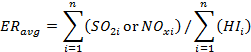
Where:
| ER avg | =
|
average annual or ozone season emission rate in lbs/mmBtu of all EGUs in the CPS group. |
| HI i | =
|
heat input for the annual or ozone control period of each EGU, in mmBtu. |
| SO 2i | =
|
actual annual SO 2 lbs of each EGU in the CPS group, as set forth in subsection (b). |
| NO xi | =
|
actual annual or ozone season NO x lbs of each EGU in the CPS group. |
| n | =
|
number of EGUs that are in the CPS group. |
| i | =
|
each EGU in the CPS group. |
(Source: Amended at 39 Ill. Reg. 16225, effective December 7, 2015)
Section 225.296 Combined Pollutant Standard: Control Technology Requirements for NO x , SO 2 , and PM Emissions
a) Control Technology Requirements for NO x and SO 2 .
1) On or before December 31, 2013, the owner or operator must either permanently shut down or install and have operational FGD equipment on Waukegan 7;
2) On or before December 31, 2014, the owner or operator must either permanently shut down or install and have operational FGD equipment on Waukegan 8;
3) On or before December 31, 2015, the owner or operator must either permanently shut down or install and have operational FGD equipment on Fisk 19;
4) If Crawford 7 will be operated after December 31, 2018, and not permanently shut down by this date, the owner or operator must:
A) On or before December 31, 2015, install and have operational SNCR or equipment capable of delivering essentially equivalent NO x reductions on Crawford 7; and
B) On or before December 31, 2018, install and have operational FGD equipment on Crawford 7;
5) If Crawford 8 will be operated after December 31, 2017 and not permanently shut down by this date, the owner or operator must:
A) On or before December 31, 2015, install and have operational SNCR or equipment capable of delivering essentially equivalent NO x emissions reductions on Crawford 8; and
B) On or before December 31, 2017, install and have operational FGD equipment on Crawford 8.
b) Other Control Technology Requirements for SO 2 . On and after April 16, 2015, Will County 3 must not combust coal. On and after December 31, 2016, Joliet 6, 7, and 8 must not combust coal. Owners or operators of the other specified EGUs must permanently shut down, permanently cease combusting coal at, or install FGD equipment on each specified EGU (except Will County 4), on or before December 31, 2018, unless an earlier date is specified in subsection (a) of this Section.
c) Control Technology Requirements for PM. The owner or operator of thespecified EGU listed in this subsection that is equipped with a hot-side ESP must replace the hot-side ESP with a cold-side ESP, install an appropriately designed fabric filter, or permanently shut down the EGU by the date specified. Hot-side ESP means an ESP on a coal-fired boiler that is installed before the boiler's air-preheater where the operating temperature is typically at least 550ºF, as distinguished from a cold-side ESP that is installed after the air pre-heater where the operating temperature is typically no more than 350ºF.
Waukegan 7 on or before December 31, 2013.
d) Beginning on December 31, 2008, and annually thereafter up to and including December 31, 2015, the owner or operator of the Fisk power plant must submit in writing to the Agency a report on any technology or equipment designed to affect air quality that has been considered or explored for the Fisk power plant in the preceding 12 months. This report will not obligate the owner or operator to install any equipment described in the report.
e) Notwithstanding 35 Ill. Adm. Code 201.146(hhh), until an EGU has complied with the applicable requirements of subsections 225.296(a), (b), and (c), the owner or operator of the EGU must obtain a construction permit for any new or modified air pollution control equipment that it proposes to construct for control of emissions of mercury, NO x , PM, or SO 2 .
(Source: Amended at 39 Ill. Reg. 16225, effective December 7, 2015)
Section 225.297 Combined Pollutant Standard: Permanent Shut-Downs
a) The owner or operator of the following EGUs must permanently shut down the EGU by the dates specified:
1) Waukegan 6 on or before December 31, 2007; and
2) Will County 1 and Will County 2 on or before December 31, 2010.
b) No later than 8 months before the date that a specified EGU will be permanently shut down, the owner or operator must submit a report to the Agency that includes a description of the actions that have already been taken to allow the shutdown of the EGU and a description of the future actions that must be accomplished to complete the shutdown of the EGU, with the anticipated schedule for those actions and the anticipated date of permanent shutdown of the unit.
c) No later than six months before a specified EGU will be permanently shut down, the owner or operator shall apply for revisions to the operating permits for the EGU to include provisions that terminate the authorization to operate the unit on that date.
d) If after applying for or obtaining a construction permit to install required control equipment, the owner or operator decides to permanently shut-down a Specified EGU rather than install the required control technology, the owner or operator must immediately notify the Agency in writing and thereafter submit the information required by subsections (b) and (c) of this Section.
e) Failure to permanently shut down a specified EGU by the required date shall be considered separate violations of the applicable emissions standards and control technology requirements of the CPS for NO x , PM, SO 2 , and mercury.
(Source: Added at 33 Ill. Reg. 10427, effective June 26, 2009)
Section 225.298 Combined Pollutant Standard: Requirements for NO x and SO 2 Allowances
a) The following requirements apply to the owner and operator with respect to SO 2 and NO x allowances, which mean, for the purposes of this Section 225.298, allowances necessary for compliance with Section 225.310, 225.410, or 225.510, 40 CFR 72, or subparts AA and AAAA of 40 CFR 96, or any future federal NO x or SO 2 emissions trading programs that modify or replace these programs:
1) The owner or operator of specified EGUs in a CPS group may sell, trade, or transfer any and all SO 2 and NO x emissions allowances of any vintage (the year an allowance is issued) owned, allocated to, or earned by the specified EGUs (the "CPS allowances"), without restriction, to any person or entity located anywhere, except that the owner or operator may not directly sell, trade, or transfer CPS allowances to a unit located in Ohio, Indiana, Illinois, Wisconsin, Michigan, Kentucky, Missouri, Iowa, Minnesota, or Texas.
2) In no event shall this subsection (a) require or be interpreted to require any restriction whatsoever on the sale, trade, or exchange of the CPS allowances by persons or entities who have acquired the CPS allowances from the owner or operator of specified EGUs in a CPS group.
b) The owner or operator of EGUs in a specified CPS group is prohibited from purchasing or using SO 2 and NO x allowances for the purposes of meeting the SO 2 and NO x emissions standards set forth in Section 225.295.
c) By March 1, 2010, and continuing each year thereafter, the owner or operator of the EGUs in a CPS group must submit a report to the Agency that demonstrates compliance with the requirements of this Section for the previous calendar year and ozone season control period (May 1 through September 30), and includes identification of any NO x or SO 2 allowances that have been used for compliance with any NO x or SO 2 trading programs, and any NO x or SO 2 allowances that were sold, gifted, used, exchanged, or traded. A final report must be submitted to the Agency by August 31 of each year, providing either verification that the actions described in the initial report have taken place, or, if such actions have not taken place, an explanation of the changes that have occurred and the reasons for such changes.
(Source: Amended at 39 Ill. Reg. 16225, effective December 7, 2015)
Section 225.299 Combined Pollutant Standard: Clean Air Act Requirements
The SO 2 emissions rates set forth in the CPS shall be deemed to be best available retrofit technology (“BART”) under the Visibility Protection provisions of the CAA (42 USC 7491), reasonably available control technology (“RACT”) and reasonably available control measures (“RACM”) for achieving fine particulate matter (“PM 2.5 ”) requirements under NAAQS in effect on August 31, 2007, as required by the CAA (42 USC 7502). The Agency may use the SO 2 and NO x emissions reductions required under the CPS in developing attainment demonstrations and demonstrating reasonable further progress for PM 2.5 and 8 hour ozone standards, as required under the CAA. Furthermore, in developing rules, regulations, or State Implementation Plans designed to comply with PM 2.5 and 8 hour ozone NAAQS, the Agency, taking into account all emission reduction efforts and other appropriate factors, will use best efforts to seek SO 2 and NO x emissions rates from other EGUs that are equal to or less than the rates applicable to the CPS group and will seek SO 2 and NO x reductions from other sources before seeking additional emissions reductions from any EGU in the CPS group.
(Source: Added at 33 Ill. Reg. 10427, effective June 26, 2009)
SUBPART C: CLEAN AIR ACT INTERSTATE RULE (CAIR) SO 2 TRADING PROGRAM
Section 225.300 Purpose
The purpose of this Subpart C is to control the emissions of sulfur dioxide (SO 2 ) from EGUs annually by implementing the CAIR SO 2 Trading Program pursuant to 40 CFR 96, as incorporated by reference in Section 225.140.
(Source: Added at 31 Ill. Reg. 12864, effective August 31, 2007)
Section 225.305 Applicability
a) Except as provided in subsections (b)(1), (b)(3), and (b)(4) of this Section:
1) The following units are CAIR SO 2 units, and any source that includes one or more such units is a CAIR SO 2 source subject to the requirements of this Subpart C: any stationary, fossil-fuel-fired boiler or stationary, fossil-fuel-fired combustion turbine serving at any time, since the later of November 15, 1990 or the start-up of the unit’s combustion chamber, a generator with nameplate capacity of more than 25 MWe producing electricity for sale.
2) If a stationary boiler or stationary combustion turbine that, pursuant to subsection (a)(1) of this Section, is not a CAIR SO 2 unit begins to combust fossil fuel or to serve a generator with nameplate capacity of more than 25 MWe producing electricity for sale, the unit will become a CAIR SO 2 unit as provided in subsection (a)(1) of this Section on the first date on which it both combusts fossil fuel and serves such generator.
b) The units that meet the requirements set forth in subsections (b)(1), (b)(3), and (b)(4) of this Section will not be CAIR SO 2 units and units that meet the requirements of subsections (b)(2) and (b)(5) of this Section are CAIR SO 2 units:
1) Any unit that would otherwise be classified as a CAIR SO 2 unit pursuant to subsection (a)(1) or (a)(2) of this Section and:
A) Qualifies as a cogeneration unit during the 12-month period starting on the date the unit first produces electricity and continues to qualify as a cogeneration unit; and
B) Does not serve at any time, since the later of November 15, 1990 or the start-up of the unit’s combustion chamber, a generator with nameplate capacity of more than 25 MWe supplying any calendar year more than one-third of the unit’s potential electric output capacity or 219,000 MWh, whichever is greater, to any utility power distribution for sale.
2) If a unit qualifies as a cogeneration unit during the 12-month period starting on the date the unit first produces electricity and meets the requirements of subsection (b)(1) of this Section for at least one calendar year, but subsequently no longer meets all such requirements, the unit shall become a CAIR SO 2 unit starting on the earlier of January 1 after the first calendar year during which the unit no longer qualifies as a cogeneration unit or January 1 after the first calendar year during which the unit no longer meets the requirements of subsection (b)(1)(B) of this Section.
3) Any unit that would otherwise be classified as a CAIR SO 2 unit pursuant to subsection (a)(1) or (a)(2) of this Section commencing operation before January 1, 1985 and:
A) Qualifies as a solid waste incineration unit; and
B) Has an average annual fuel consumption of non-fossil fuel for 1985-1987 exceeding 80 percent (on a Btu basis) and an average annual fuel consumption of non-fossil fuel for any three consecutive calendar years after 1990 exceeding 80 percent (on a Btu basis).
4) Any unit that would otherwise be classified as a CAIR SO 2 unit under subsection (a)(1) or (a)(2) of this Section commencing operation on or after January 1, 1985 and:
A) Qualifies as a solid waste incineration unit; and
B) Has an average annual fuel consumption of non-fossil fuel the first three years of operation exceeding 80 percent (on a Btu basis) and an average annual fuel consumption of non-fossil fuel for any three consecutive calendar years after 1990 exceeding 80 percent (on a Btu basis).
5) If a unit qualifies as a solid waste incineration unit and meets the requirements of subsection (b)(3) or (b)(4) of this Section for at least three consecutive years, but subsequently no longer meets all such requirements, the unit shall become a CAIR SO2 unit starting on the earlier of January 1 after the first three consecutive calendar years after 1990 for which the unit has an average annual fuel consumption of 20 percent or more.
(Source: Added at 31 Ill. Reg. 12864, effective August 31, 2007)
Section 225.310 Compliance Requirements
a) The designated representative of a CAIR SO 2 unit must comply with the requirements of the CAIR SO 2 Trading Program for Illinois as set forth in this Subpart C and 40 CFR 96, subpart AAA (CAIR SO 2 Trading Program General Provisions, excluding 40 CFR 96.204, and 96.206); 40 CFR 96, subpart BBB (CAIR Designated Representative for CAIR SO 2 Sources); 40 CFR 96, subpart FFF (CAIR SO 2 Allowance Tracking System); 40 CFR 96, subpart GGG (CAIR SO 2 Allowance Transfers); and 40 CFR 96, subpart HHH (Monitoring and Reporting); as incorporated by reference in Section 225.140 .
b) Permit requirements:
1) The owner or operator of each source with one or more CAIR SO 2 units at the source must apply for a permit issued by the Agency with federally enforceable conditions covering the CAIR SO 2 Trading Program (“CAIR permit”) that complies with the requirements of Section 225.320 (Permit Requirements).
2) The owner or operator of each CAIR SO 2 source and each CAIR SO 2 unit at the source must operate the CAIR SO 2 unit in compliance with its CAIR permit.
c) Monitoring requirements:
1) The owner or operator of each CAIR SO 2 source and each CAIR SO 2 unit at the source must comply with the monitoring, reporting and recordkeeping requirements of 40 CFR 96, subpart HHH. The CAIR designated representative of each CAIR SO 2 source and each CAIR SO 2 unit at the CAIR SO 2 source must comply with those sections of the monitoring, reporting and recordkeeping requirements of 40 CFR 96, subpart HHH, applicable to the CAIR designated representative.
2) The compliance of each CAIR SO 2 source with the emissions limitation pursuant to subsection (d) of this Section will be determined by the emissions measurements recorded and reported in accordance with 40 CFR 96, subpart HHH and 40 CFR 75.
d) Emission requirements:
1) By the allowance transfer deadline, midnight of March 1, 2011, and by midnight of March 1 of each subsequent year if March 1 is a business day, the owner or operator of each CAIR SO 2 source and each CAIR SO 2 unit at the source must hold a tonnage equivalent in CAIR SO 2 allowances available for compliance deductions pursuant to 40 CFR 96.254(a) and (b) in the CAIR SO 2 source’s CAIR SO 2 compliance account. If March 1 is not a business day, the allowance transfer deadline means by midnight of the first business day thereafter. The number of allowances held on the allowance transfer deadline may not be less than the total tonnage equivalent of the tons of SO 2 emissions for the control period from all CAIR SO 2 units at the CAIR SO 2 source, as determined in accordance with 40 CFR 96, subpart HHH.
2) Each ton of excess emissions of SO 2 emitted by a CAIR SO 2 source for each day of a control period, starting in 2010 will constitute a separate violation of this Subpart C, the Clean Air Act, and the Act.
3) Each CAIR SO 2 unit will be subject to the requirements of subsection (d)(1) of this Section for the control period starting on the later of January 1, 2010 or the deadline for meeting the unit’s monitoring certification requirements pursuant to 40 CFR 96.270(b)(1) or (2) and for each control period thereafter.
4) CAIR SO 2 allowances must be held in, deducted from, or transferred into or among allowance accounts in accordance with this Subpart and 40 CFR 96, subparts FFF and GGG.
5) In order to comply with the requirements of subsection (d)(1) of this Section, a CAIR SO 2 allowance may not be deducted for compliance according to subsection (d)(1) of this Section for a control period in a calendar year before the year for which the allowance is allocated.
6) A CAIR SO 2 allowance is a limited authorization to emit SO 2 in accordance with the CAIR SO 2 Trading Program. No provision of the CAIR SO 2 Trading Program, the CAIR permit application, the CAIR permit, or a retired unit exemption pursuant to 40 CFR 96.205, and no provision of law, will be construed to limit the authority of the United States or the State to terminate or limit this authorization.
7) A CAIR SO 2 allowance does not constitute a property right.
8) Upon recordation by USEPA pursuant to 40 CFR 96 subpart FFF or subpart GGG, every allocation, transfer, or deduction of a CAIR SO 2 allowance to or from a CAIR SO 2 source’s compliance account is deemed to amend automatically, and become a part of, any CAIR permit of the CAIR SO 2 source. This automatic amendment of the CAIR permit will be deemed an operation of law and will not require any further review.
e) Recordkeeping and reporting requirements:
1) Unless otherwise provided, the owner or operator of the CAIR SO 2 source and each CAIR SO 2 unit at the source must keep on site at the source each of the documents listed in subsections (e)(1)(A) through (e)(1)(D) of this Section for a period of five years from the date the document is created. This period may be extended for cause, at any time prior to the end of five years, in writing by the Agency or USEPA.
A) The certificate of representation for the CAIR designated representative for the source and each CAIR SO 2 unit at the source, all documents that demonstrate the truth of the statements in the certificate of representation, provided that the certificate and documents must be retained on site at the source beyond such five-year period until the documents are superseded because of the submission of a new certificate of representation, pursuant to 40 CFR 96.213, changing the CAIR designated representative.
B) All emissions monitoring information, in accordance with 40 CFR 96, subpart HHH.
C) Copies of all reports, compliance certifications, and other submissions and all records made or required pursuant to the CAIR SO 2 Trading Program or documents necessary to demonstrate compliance with the requirements of the CAIR SO 2 Trading Program or with the requirements of this Subpart C.
D) Copies of all documents used to complete a CAIR permit application and any other submission or documents used to demonstrate compliance pursuant to the CAIR SO 2 Trading Program.
2) The CAIR designated representative of a CAIR SO 2 source and each CAIR SO 2 unit at the source must submit to the Agency and USEPA the reports and compliance certifications required pursuant to the CAIR SO 2 Trading Program, including those pursuant to 40 CFR 96, subpart HHH.
f) Liability:
1) No revision of a permit for a CAIR SO 2 unit may excuse any violation of the requirements of this Subpart C or the requirements of the CAIR SO 2 Trading Program.
2) Each CAIR SO 2 source and each CAIR SO 2 unit must meet the requirements of the CAIR SO 2 Trading Program.
3) Any provision of the CAIR SO 2 Trading Program that applies to a CAIR SO 2 source (including any provision applicable to the CAIR designated representative of a CAIR SO 2 source) will also apply to the owner and operator of the CAIR SO 2 source and to the owner and operator of each CAIR SO 2 unit at the source.
4) Any provision of the CAIR SO 2 Trading Program that applies to a CAIR SO 2 unit (including any provision applicable to the CAIR designated representative of a CAIR SO 2 unit) will also apply to the owner and operator of the CAIR SO 2 unit.
5) The CAIR designated representative of a CAIR SO 2 unit that has excess SO 2 emissions in any control period must surrender the allowances as required for deduction pursuant to 40 CFR 96.254(d)(1).
6) The owner or operator of a CAIR SO 2 unit that has excess SO 2 emissions in any control period must pay any fine, penalty, or assessment or comply with any other remedy imposed pursuant to the Act and 40 CFR 96.254(d)(2).
g) Effect on other authorities: No provision of the CAIR SO 2 Trading Program, a CAIR permit application, a CAIR permit, or a retired unit exemption pursuant to 40 CFR 96.205 will be construed as exempting or excluding the owner and operator and, to the extent applicable, the CAIR designated representative of a CAIR SO 2 source or a CAIR SO 2 unit from compliance with any other regulation promulgated pursuant to the CAA, the Act, any State regulation or permit, or a federally enforceable permit.
(Source: Added at 31 Ill. Reg. 12864, effective August 31, 2007)
Section 225.315 Appeal Procedures
The appeal procedures for decisions of USEPA pursuant to the CAIR SO 2 Trading Program are set forth in 40 CFR 78, as incorporated by reference in Section 225.140.
(Source: Added at 31 Ill. Reg. 12864, effective August 31, 2007)
Section 225.320 Permit Requirements
a) Permit requirements:
1) The owner or operator of each source with a CAIR SO 2 unit is required to submit:
A) A complete permit application addressing all applicable CAIR SO 2 Trading Program requirements for a permit meeting the requirements of this Section, applicable to each CAIR SO 2 unit at the source. Each CAIR permit must contain elements required for a complete CAIR permit application pursuant to subsection (b)(2) of this Section.
B) Any supplemental information that the Agency determines is necessary in order to review a CAIR permit application and issue a CAIR permit.
2) Each CAIR permit will be issued pursuant to Section 39 or 39.5 of the Act, must contain federally enforceable conditions addressing all applicable CAIR SO 2 Trading Program requirements, and will be a complete and segregable portion of the source’s entire permit pursuant to subsection (a)(1) of this Section.
3) No CAIR permit may be issued until the Agency and USEPA have received a complete certificate of representation for a CAIR designated representative or alternate designated representative pursuant to 40 CFR 96, subpart BBB, for a source and the CAIR SO 2 unit at the source.
4) For all CAIR SO 2 units that commenced operation before July 1, 2008, the owner or operator of the unit must submit a CAIR permit application meeting the requirements of this Section on or before July 1, 2008.
5) For CAIR SO 2 units that commence operation on or after July 1, 2008, and that are and are not subject to Section 39.5 of the Act, the owner or operator of such units must submit applications for construction and operating permits pursuant to the requirements of Sections 39 and 39.5 of the Act, as applicable, and 35 Ill. Adm. Code 201 and the applications must specify that they are applying for CAIR permits and must address the CAIR permit application requirements of this Section.
b) Permit applications:
1) Duty to apply: The owner or operator of any source with one or more CAIR SO 2 units must submit to the Agency a CAIR permit application for the source covering each CAIR SO 2 unit pursuant to subsection (b)(2) of this Section by the applicable deadline in subsection (a)(4) or (a)(5) of this Section. The owner or operator of any source with one or more CAIR SO 2 units must reapply for a CAIR permit for the source as required by this Subpart, 35 Ill. Adm. Code 201, and, as applicable, Sections 39 and 39.5 of the Act.
2) Information requirements for CAIR permit applications: A complete CAIR permit application must include the following elements concerning the source for which the application is submitted:
A) Identification of the source, including plant name. The ORIS (Office of Regulatory Information Systems) or facility code assigned to the source by the Energy Information Administration must also be included, if applicable;
B) Identification of each CAIR SO 2 unit at the source; and
C) The compliance requirements applicable to each CAIR SO 2 unit as set forth in Section 225.310.
3) An application for a CAIR permit will be treated as a modification of the CAIR SO 2 source’s existing federally enforceable permit, if such a permit has been issued for that CAIR SO 2 source, and will be subject to the same procedural requirements. When the Agency issues a CAIR permit pursuant to the requirements of this Section, it will be incorporated into and become part of that CAIR SO 2 source’s existing federally enforceable permit.
c) Permit content: Each CAIR permit is deemed to incorporate automatically the definitions and terms specified in 225.130 and 40 CFR 96.202, as incorporated by reference in Section 225.140 and, upon recordation of USEPA under 40 CFR 96, subparts FFF and GGG, as incorporated by reference in Section 225.140, every allocation, transfer, or deduction of a CAIR SO 2 allowance to or from the compliance account of the CAIR SO 2 source covered by the permit.
(Source: Added at 31 Ill. Reg. 12864, effective August 31, 2007)
Section 225.325 Trading Program
a) The CAIR SO 2 Trading Program is administered by USEPA. CAIR SO 2 allowances are issued as described by the definition for allocate in 40 CFR 96. 202, as incorporated by reference in Section 225.140. The amount of CAIR SO 2 allowances to be credited to a CAIR SO 2 source’s CAIR SO 2 Allowance Tracking System account for a CAIR SO 2 unit will be determined in accordance with 40 CFR 96.253, as incorporated by reference in Section 225.140.
b) A CAIR SO 2 allowance is a limited authorization to emit SO 2 during the calendar year for which the allowance is allocated or any calendar year thereafter pursuant to the CAIR SO 2 Trading Program as follows:
1) For one CAIR SO 2 allowance allocated for a control period in a year before 2010, one ton of SO 2 , except as provided for in the compliance deductions pursuant to 40 CFR 96.254(b);
2) For one CAIR SO 2 allowance allocated for a control period in 2010 through 2014, 0.50 ton of SO 2 , except as provided for in the compliance deductions pursuant to 40 CFR 96.254(b); and
3) For one CAIR SO 2 allowance allocated for a control period in 2015 or later, 0.35 ton of SO 2 , except as provided for in the compliance deductions pursuant to 40 CFR 96.254(b).
(Source: Added at 31 Ill. Reg. 12864, effective August 31, 2007)
SUBPART D: CAIR NO x ANNUAL TRADING PROGRAM
Section 225.400 Purpose
The purpose of this Subpart D is to control the annual emissions of nitrogen oxides (NO x ) from EGUs by determining allocations and implementing the CAIR NO x Annual Trading Program.
(Source: Added at 31 Ill. Reg. 12864, effective August 31, 2007)
Section 225.405 Applicability
a) Except as provided in subsections (b)(1), (b)(3), and (b)(4) of this Section:
1) The following units are CAIR NO x units, and any source that includes one or more such units is a CAIR NO x source subject to the requirements of this Subpart D: any stationary, fossil-fuel-fired boiler or stationary, fossil-fuel-fired combustion turbine serving at any time, since the later of November 15, 1990 or the start-up of the unit’s combustion chamber, a generator with nameplate capacity of more than 25 MWe producing electricity for sale.
2) If a stationary boiler or stationary combustion turbine that, pursuant to subsection (a)(1) of this Section, is not a CAIR NO x unit begins to combust fossil fuel or to serve a generator with nameplate capacity of more than 25 MWe producing electricity for sale, the unit will become a CAIR NO x unit as provided in subsection (a)(1) of this Section on the first date on which it both combusts fossil fuel and serves such generator.
b) The units that meet the requirements set forth in subsections (b)(1), (b)(3), and (b)(4) of this Section will not be CAIR NO x units and units that meet the requirements of subsections (b)(2) and (b)(5) of this Section are CAIR NO x units:
1) Any unit that would otherwise be classified as a CAIR NO x unit pursuant to subsection (a)(1) or (a)(2) of this Section and:
A) Qualifies as a cogeneration unit during the 12-month period starting on the date the unit first produces electricity and continues to qualify as a cogeneration unit; and
B) Does not serve at any time, since the later of November 15, 1990 or the start-up of the unit’s combustion chamber, a generator with nameplate capacity of more than 25 MWe supplying any calendar year more than one-third of the unit’s potential electric output capacity or 219,000 MWh, whichever is greater, to any utility power distribution for sale.
2) If a unit qualifies as a cogeneration unit during the 12-month period starting on the date the unit first produces electricity and meets the requirements of subsection (b)(1) of this Section for at least one calendar year, but subsequently no longer meets all such requirements, the unit shall become a CAIR NO x unit starting on the earlier of January 1 after the first calendar year during which the unit no longer qualifies as a cogeneration unit or January 1 after the first calendar year during which the unit no longer meets the requirements of subsection (b)(1)(B) of this Section.
3) Any unit that would otherwise be classified as a CAIR NO x unit pursuant to subsection (a)(1) or (a)(2) of this Section commencing operation before January 1, 1985 and:
A) Qualifies as a solid waste incineration unit; and
B) Has an average annual fuel consumption of non-fossil fuel for 1985-1987 exceeding 80 percent (on a Btu basis) and an average annual fuel consumption of non-fossil fuel for any three consecutive calendar years after 1990 exceeding 80 percent (on a Btu basis).
4) Any unit that would otherwise be classified as a CAIR NO x unit under subsection (a)(1) or (a)(2) of this Section commencing operation on or after January 1, 1985 and:
A) Qualifies as a solid waste incineration unit; and
B) Has an average annual fuel consumption of non-fossil fuel the first three years of operation exceeding 80 percent (on a Btu basis) and an average annual fuel consumption of non-fossil fuel for any three consecutive calendar years after 1990 exceeding 80 percent (on a Btu basis).
5) If a unit qualifies as a solid waste incineration unit and meets the requirements of subsection (b)(3) or (b)(4) of this Section for at least three consecutive years, but subsequently no longer meets all such requirements, the unit shall become a CAIR NO x unit starting on the earlier of January 1 after the first three consecutive calendar years after 1990 for which the unit has an average annual fuel consumption of 20 percent or more.
(Source: Added at 31 Ill. Reg. 12864, effective August 31, 2007)
Section 225.410 Compliance Requirements
a) The designated representative of a CAIR NO x unit must comply with the requirements of the CAIR NO x Annual Trading Program for Illinois as set forth in this Subpart D and 40 CFR 96, subpart AA (NO x Annual Trading Program General Provisions, excluding 40 CFR 96.104, 96.105(b)(2), and 96.106); 40 CFR 96, subpart BB (CAIR Designated Representative for CAIR NO x Sources); 40 CFR 96, subpart FF (CAIR NO x Allowance Tracking System); 40 CFR 96, subpart GG (CAIR NO x Allowance Transfers); and 40 CFR 96, subpart HH (Monitoring and Reporting); as incorporated by reference in Section 225.140.
b) Permit requirements:
1) The designated representative of each source with one or more CAIR NO x units at the source must apply for a permit issued by the Agency with federally enforceable conditions covering the CAIR NO x Annual Trading Program (“CAIR permit”) that complies with the requirements of Section 225.420 (Permit Requirements).
2) The owner or operator of each CAIR NO x source and each CAIR NO x unit at the source must operate the CAIR NO x unit in compliance with its CAIR permit.
c) Monitoring requirements:
1) The owner or operator of each CAIR NO x source and each CAIR NO x unit at the source must comply with the monitoring, reporting, and recordkeeping requirements of 40 CFR 96, subpart HH and Section 225.450. The CAIR designated representative of each CAIR NO x source and each CAIR NO x unit at the CAIR NO x source must comply with those sections of the monitoring, reporting and recordkeeping requirements of 40 CFR 96, subpart HH, applicable to a CAIR designated representative.
2) The compliance of each CAIR NO x source with the NO x emissions limitation pursuant to subsection (d) of this Section will be determined by the emissions measurements recorded and reported in accordance with 40 CFR 96, subpart HH.
d) Emission requirements:
1) By the allowance transfer deadline, midnight of March 1, 2010, and by midnight March 1 of each subsequent year if March 1 is a business day, the owner or operator of each CAIR NO x source and each CAIR NO x unit at the source must hold CAIR NO x allowances available for compliance deductions pursuant to 40 CFR 96.154(a) in the CAIR NO x source’s CAIR NO x compliance account. If March 1 is not a business day, the allowance transfer deadline means by midnight of the first business day thereafter. The number of allowances held on the allowance transfer deadline may not be less than the tons of NO x emissions for the control period from all CAIR NO x units at the source, as determined in accordance with 40 CFR 96, subpart HH.
2) Each ton of excess emissions of a CAIR NO x source for each day in a control period, starting in 2009, will constitute a separate violation of this Subpart D, the Act, and the CAA.
3) Each CAIR NO x unit will be subject to the requirements of subsection (d)(1) of this Section for the control period starting on the later of January 1, 2009 or the deadline for meeting the unit’s monitoring certification requirements pursuant to 40 CFR 96.170(b)(1) or (b)(2) and for each control period thereafter.
4) CAIR NO x allowances must be held in, deducted from, or transferred into or among allowance accounts in accordance with this Subpart and 40 CFR 96, subparts FF and GG.
5) In order to comply with the requirements of subsection (d)(1) of this Section, a CAIR NO x allowance may not be deducted for compliance according to subsection (d)(1) of this Section for a control period in a year before the calendar year for which the allowance is allocated.
6) A CAIR NO x allowance is a limited authorization to emit one ton of NO x in accordance with the CAIR NO x Trading Program. No provision of the CAIR NO x Trading Program, the CAIR NO x permit application, the CAIR permit, or a retired unit exemption pursuant to 40 CFR 96.105, and no provision of law, will be construed to limit the authority of the United States or the State to terminate or limit this authorization.
7) A CAIR NO x allowance does not constitute a property right.
8) Upon recordation by USEPA pursuant to 40 CFR 96, subpart FF or subpart GG, every allocation, transfer, or deduction of a CAIR NO x allowance to or from a CAIR NO x source compliance account is deemed to amend automatically, and become a part of, any CAIR NO x permit of the CAIR NO x source. This automatic amendment of the CAIR permit will be deemed an operation of law and will not require any further review.
e) Recordkeeping and reporting requirements:
1) Unless otherwise provided, the owner or operator of the CAIR NO x source and each CAIR NO x unit at the source must keep on site at the source each of the documents listed in subsections (e)(1)(A) through (e)(1)(E) of this Section for a period of five years from the date the document is created. This period may be extended for cause, at any time prior to the end of five years, in writing by the Agency or USEPA.
A) The certificate of representation for the CAIR designated representative for the source and each CAIR NO x unit at the source, all documents that demonstrate the truth of the statements in the certificate of representation, provided that the certificate and documents must be retained on site at the source beyond such five-year period until the documents are superseded because of the submission of a new certificate of representation, pursuant to 40 CFR 96.113, changing the CAIR designated representative.
B) All emissions monitoring information, in accordance with 40 CFR 96, subpart HH.
C) Copies of all reports, compliance certifications, and other submissions and all records made or required pursuant to the CAIR NO x Annual Trading Program or documents necessary to demonstrate compliance with the requirements of the CAIR NO x Annual Trading Program or with the requirements of this Subpart D.
D) Copies of all documents used to complete a CAIR NO x permit application and any other submission or documents used to demonstrate compliance pursuant to the CAIR NO x Annual Trading Program.
E) Copies of all records and logs for gross electrical output and useful thermal energy required by Section 225.450.
2) The CAIR designated representative of a CAIR NO x source and each CAIR NO x unit at the source must submit to the Agency and USEPA the reports and compliance certifications required pursuant to the CAIR NO x Annual Trading Program, including those pursuant to 40 CFR 96, subpart HH.
f) Liability:
1) No revision of a permit for a CAIR NO x unit may excuse any violation of the requirements of this Subpart D or the requirements of the CAIR NO x Annual Trading Program.
2) Each CAIR NO x source and each CAIR NO x unit must meet the requirements of the CAIR NO x Annual Trading Program.
3) Any provision of the CAIR NO x Annual Trading Program that applies to a CAIR NO x source (including any provision applicable to the CAIR designated representative of a CAIR NO x source) will also apply to the owner and operator of the CAIR NO x source and to the owner and operator of each CAIR NO x unit at the source.
4) Any provision of the CAIR NO x Annual Trading Program that applies to a CAIR NO x unit (including any provision applicable to the CAIR designated representative of a CAIR NO x unit) will also apply to the owner and operator of the CAIR NO x unit.
5) The CAIR designated representative of a CAIR NO x unit that has excess emissions in any control period must surrender the allowances as required for deduction pursuant to 40 CFR 96.154(d)(1).
6) The owner or operator of a CAIR NO x unit that has excess NO x emissions in any control period must pay any fine, penalty, or assessment or comply with any other remedy imposed pursuant to the Act and 40 CFR 96.154(d)(2).
g) Effect on other authorities: No provision of the CAIR NO x Annual Trading Program, a CAIR permit application, a CAIR permit, or a retired unit exemption pursuant to 40 CFR 96.105 will be construed as exempting or excluding the owner and operator and, to the extent applicable, the CAIR designated representative of a CAIR NO x source or a CAIR NO x unit from compliance with any other regulation promulgated pursuant to the CAA, the Act, any State regulation or permit, or a federally enforceable permit.
(Source: Added at 31 Ill. Reg. 12864, effective August 31, 2007)
Section 225.415 Appeal Procedures
The appeal procedures for decisions of USEPA pursuant to the CAIR NO x Annual Trading Program are set forth in 40 CFR 78, as incorporated by reference in Section 225.140.
(Source: Added at 31 Ill. Reg. 12864, effective August 31, 2007)
Section 225.420 Permit Requirements
a) Permit requirements:
1) The owner or operator of each source with a CAIR NO x unit is required to submit:
A) A complete permit application addressing all applicable CAIR NO x Annual Trading Program requirements for a permit meeting the requirements of this Section, applicable to each CAIR NO x unit at the source. Each CAIR permit must contain elements required for a complete CAIR permit application pursuant to subsection (b)(2) of this Section.
B) Any supplemental information that the Agency determines necessary in order to review a CAIR permit application and issue any CAIR permit.
2) Each CAIR permit will be issued pursuant to Sections 39 and 39.5 of the Act, must contain federally enforceable conditions addressing all applicable CAIR NO x Annual Trading Program requirements, and will be a complete and segregable portion of the source’s entire permit pursuant to subsection (a)(1) of this Section.
3) No CAIR permit may be issued until the Agency and USEPA have received a complete certificate of representation for a CAIR designated representative pursuant to 40 CFR 96, subpart BB, for the CAIR NO x source and the CAIR NO x unit at the source.
4) For all CAIR NO x units that commenced operation before December 31, 2007, the owner or operator of the unit must submit a CAIR permit application meeting the requirements of this Section on or before December 31, 2007.
5) For all CAIR NO x units that commence operation on or after December 31, 2007, the owner or operator of these units must submit applications for construction and operating permits pursuant to the requirements of Sections 39 and 39.5 of the Act, as applicable, and 35 Ill. Adm. Code 201 and the applications must specify that they are applying for CAIR permits and must address the CAIR permit application requirements of this Section.
b) Permit applications:
1) Duty to apply: The owner or operator of any source with one or more CAIR NO x units must submit to the Agency a CAIR permit application for the source covering each CAIR NO x unit pursuant to subsection (b)(2) of this Section by the applicable deadline in subsection (a)(4) or (a)(5) of this Section. The owner or operator of any source with one or more CAIR NO x units must reapply for a CAIR permit for the source as required by this Subpart, 35 Ill. Adm. Code 201, and, as applicable, Sections 39 and 39.5 of the Act.
2) Information requirements for CAIR permit applications: A complete CAIR permit application must include the following elements concerning the source for which the application is submitted:
A) Identification of the source, including plant name. The ORIS (Office of Regulatory Information Systems) or facility code assigned to the source by the Energy Information Administration must also be included, if applicable;
B) Identification of each CAIR NO x unit at the source; and
C) The compliance requirements applicable to each CAIR NO x unit as set forth in Section 225.410.
3) An application for a CAIR permit will be treated as a modification of the CAIR NO x source’s existing federally enforceable permit, if such a permit has been issued for that source, and will be subject to the same procedural requirements. When the Agency issues a CAIR permit pursuant to the requirements of this Section, it will be incorporated into and become part of that source’s existing federally enforceable permit.
c) Permit content: Each CAIR permit is deemed to incorporate automatically the definitions and terms specified in Section 225.130 and 40 CFR 96.102, as incorporated by reference in Section 225.140 and, upon recordation of USEPA under 40 CFR 96, subparts FF and GG, as incorporated by reference in Section 225.140, every allocation, transfer, or deduction of a CAIR NO x allowance to or from the compliance account of the CAIR NO x source covered by the permit.
(Source: Added at 31 Ill. Reg. 12864, effective August 31, 2007)
Section 225.425 Annual Trading Budget
The CAIR NO x Annual Trading budget available for allowance allocations for each control period will be determined as follows:
a) The total base CAIR NO x Annual Trading budget is 76,230 tons per control period for the years 2009 through 2014, subject to a reduction for two set-asides, the New Unit Set-Aside (NUSA) and the Clean Air Set-Aside (CASA). Five percent of the budget will be allocated to the NUSA and 25 percent will be allocated to the CASA, resulting in a CAIR NO x Annual Trading budget of 53,361 tons available for allocation per control period pursuant to Section 225.440. The requirements of the NUSA are set forth in Section 225.445, and the requirements of the CASA are set forth in Sections 225.455 through 225.470.
b) The total base CAIR NO x Annual Trading budget is 63,525 tons per control period for the year 2015 and thereafter, subject to a reduction for two set-asides, the NUSA and the CASA. Five percent of the budget will be allocated to the NUSA and 25 percent will be allocated to the CASA, resulting in a CAIR NO x Annual Trading budget of 44,468 tons available for allocation per control period pursuant to Section 225.440.
c) If USEPA adjusts the total base CAIR NO x Annual Trading budget for any reason, the Agency will adjust the base CAIR NO x Annual Trading budget and the CAIR NO x Annual Trading budget available for allocation, accordingly.
(Source: Added at 31 Ill. Reg. 12864, effective August 31, 2007)
Section 225.430 Timing for Annual Allocations
a) On or before September 25, 2007, the Agency will submit to USEPA the CAIR NO x allowance allocations, in accordance with Sections 225.435 and 225.440, for the 2009, 2010, and 2011 control periods.
b) By October 31, 2008, and October 31 of each year thereafter, the Agency will submit to USEPA the CAIR NO x allowance allocations in accordance with Sections 225.435 and 225.440, for the control period four years after the year of the applicable deadline for submission pursuant to this Section. For example, on October 31, 2008, the Agency will submit to USEPA the allocations for the 2012 control period.
c) For CAIR NO x units that commence commercial operation on or after January 1, 2006, that have not been allocated allowances under Section 225.440 for the applicable or any preceding control period, the Agency will allocate allowances from the NUSA in accordance with Section 255.445. The Agency will report these allocations to USEPA by October 31 of the applicable control period. For example, on October 31, 2009, the Agency will submit to USEPA the allocations from the NUSA for the 2009 control period.
d) The Agency will allocate allowances from the CASA to energy efficiency, renewable energy, and clean technology projects pursuant to the criteria in Sections 225.455 through 225.470. The Agency will report these allocations to USEPA by October 1 of each year. For example, on October 1, 2009, the Agency will submit to USEPA the allocations from the CASA for the 2009 control period, based on reductions made in the 2008 control period.
(Source: Added at 31 Ill. Reg. 12864, effective August 31, 2007)
Section 225.435 Methodology for Calculating Annual Allocations
The Agency will calculate converted gross electrical (CGO) output, in MWh, for each CAIR NO x unit that has operated during at least one calendar year prior to the calendar year in which the Agency reports the allocations to USEPA as follows:
a) For control periods 2009, 2010, and 2011, the owner or operator of the unit must submit in writing to the Agency, by September 15, 2007, a statement that either gross electrical output data or heat input data is to be used to calculate the unit’s converted gross electrical output. The data shall be used to calculate converted gross electrical output pursuant to either subsection (a)(1) or (a)(2) of this Section:
1) Gross electrical output: If the unit has four or five control periods of data, then the gross electrical output (GO) will be the average of the unit’s three highest gross electrical outputs from the 2001, 2002, 2003, 2004, or 2005 control periods. If the unit has three or fewer control periods of gross electrical output data, the gross electrical output will be the average of those control periods for which data is available. If a generator is served by two or more units, the gross electrical output of the generator will be attributed to each unit in proportion to the unit’s share of the total control period heat input of these units for the control period. The unit’s converted gross electrical output will be calculated as follows:
A) If the unit is coal-fired:
CGO (in MWh) = GO (in MWh) ´ 1.0;
B) If the unit is oil-fired:
CGO (in MWh) = GO (in MWh) ´ 0.6; or
C) If the unit is neither coal-fired nor oil-fired:
CGO (in MWh) = GO (in MWh) ´ 0.4
2) Heat input (HI): If the unit has four or five control periods of data, the average of the unit’s three highest heat inputs from the 2001, 2002, 2003, 2004 or 2005 control period will be used. If the unit has three or fewer control periods of heat input data, the heat input will be the average of those control periods for which data is available. The unit’s converted gross electrical output will be calculated as follows:
A) If the unit is coal-fired:
CGO (in MWh) = HI (in mmBtu) ´ 0.0967;
B) If the unit is oil-fired:
CGO (in MWh) = HI (in mmBtu) ´ 0.0580; or
C) If the unit is neither coal-fired nor oil-fired:
CGO (in MWh) = HI (in mmBtu) ´ 0.0387.
b) For control periods 2012 and 2013, the owner or operator of the unit must submit in writing to the Agency, by June 1, 2008, a statement that either gross electrical output data or heat input data will be used to calculate the unit’s converted gross electrical output. The unit’s converted gross electrical output shall be calculated pursuant to either subsection (b)(1) or (b)(2) of this Section:
1) Gross electrical output: The average of the unit’s two most recent years of control period gross electrical output, if available. If a unit commences commercial operation in the 2007 control period and does not have gross electrical output for the 2006 control period, then the gross electrical output from 2007 will be used. If a generator is served by two or more units, the gross electrical output of the generator shall be attributed to each unit in proportion to the unit’s share of the total control period heat input of such units for the control period. The unit’s converted gross electrical output shall be calculated as follows:
A) If the unit is coal-fired:
CGO (in MWh) = GO (in MWh) ´ 1.0;
B) If the unit is oil-fired:
CGO (in MWh) = GO (in MWh) ´ 0.6;
C) If the unit is neither coal-fired nor oil-fired:
CGO (in MWh) = GO (in MWh) ´ 0.4.
2) Heat input: The average of the unit’s two most recent years of control period heat inputs, e.g., for the 2012 control period, the average of the unit’s heat input from the 2006 and 2007 control periods. The unit’s converted gross electrical output shall be calculated as follows:
A) If the unit is coal-fired:
CGO (in MWh) = HI (in mmBtu) ´ 0.0967;
B) If the unit is oil-fired:
CGO (in MWh) = HI (in mmBtu) ´ 0.0580; or
C) If the unit is neither coal-fired nor oil-fired:
CGO (in MWh) = HI (in mmBtu) ´ 0.0387.
c) For control period 2014 and thereafter, the unit’s gross electrical output will be the average of the unit’s two most recent control period’s gross electrical output, if available. If a unit commences commercial operation in the most recent control period and does not have gross electrical output for two control periods, the gross electrical output from the most recent period, e.g., if the unit commences commercial operation in 2009 and does not have gross electrical output from 2008, gross electrical output from 2009 will be used. If a generator is served by two or more units, the gross electrical output of the generator will be attributed to each unit in proportion to the unit’s share of the total control period heat input of these units for the control period. The unit’s converted gross electrical output will be calculated as follows:
1) If the unit is coal-fired:
CGO (in MWh) = GO (in MWh) ´ 1.0;
2) If the unit is oil-fired:
CGO (in MWh) = GO (in MWh) ´ 0.6; or
3) If the unit is neither coal-fired nor oil-fired:
CGO (in MWh) = GO (in MWh) ´ 0.4.
d) For a unit that is a combustion turbine or boiler and has equipment used to produce electricity and useful thermal energy for industrial, commercial, heating, or cooling purposes through the sequential use of energy, the Agency will add the converted gross electrical output calculated for electricity pursuant to subsection (a), (b), or (c) of this Section to the converted useful thermal energy (CUTE) to determine the total converted gross electrical output for the unit (TCGO). The Agency will determine the converted useful thermal energy by using the average of the unit’s control period useful thermal energy for the prior two control periods, if available. In the first year for which a unit is considered to be an existing unit rather than a new unit, the unit’s control period useful thermal output for the prior year will be used. The converted useful thermal energy will be determined using the following equations:
1) If the unit is coal-fired:
CUTE (in MWh) = UTE (in mmBtu) ´ 0.2930;
2) If the unit is oil-fired:
CUTE (in MWh) = UTE (in mmBtu) ´ 0.1758; or
3) If the unit is neither coal-fired nor oil-fired:
CUTE (in MWh) = UTE (in mmBtu) ´ 0.1172.
e) The CAIR NO x unit’s converted gross electrical output and converted useful thermal energy in subsections (a)(1), (b)(1), (c), and (d) of this Section for each control period will be based on the best available data reported or available to the Agency for the CAIR NO x unit pursuant to the provisions of Section 225.450.
f) The CAIR NO x unit’s heat input in subsections (a)(2) and (b)(2) of this Section for each control period will be determined in accordance with 40 CFR 75, as incorporated by reference in Section 225.140.
(Source: Added at 31 Ill. Reg. 12864, effective August 31, 2007)
Section 225.440 Annual Allocations
a) For the 2009 control period, and each control period thereafter, the Agency will allocate to all CAIR NO x units in Illinois for which the Agency has calculated the converted gross electrical output pursuant to Section 225.435(a), (b), or (c) or total converted gross electrical output pursuant to Section 225.435(d), as applicable, a total amount of CAIR NO x allowances equal to tons of NO x emissions in the CAIR NO x Annual Trading budget available for allocation as determined in Section 225.425 and as adjusted to add allowances not allocated pursuant to subsection (b) of this Section in the previous year’s allocation.
b) The Agency will allocate CAIR NO x allowances to each CAIR NO x unit on a pro-rata basis using the unit’s converted gross electrical output pursuant to Section 225.435(a), (b), or (c) or total converted gross electrical output calculated pursuant to Section 225.435(d), as applicable, to the extent whole allowances may be allocated. The Agency will retain any additional allowances beyond this allocation of whole allowances for allocation pursuant to subsection (a) of this Section in the next control period.
(Source: Added at 31 Ill. Reg. 12864, effective August 31, 2007)
Section 225.445 New Unit Set-Aside (NUSA)
For the 2009 control period and each control period thereafter, the Agency will allocate CAIR NO x allowances from the NUSA to CAIR NO x units that commenced commercial operation on or after January 1, 2006, and do not yet have an allocation for the particular control period or any preceding control period pursuant to Section 225.440, in accordance with the following procedures:
a) Beginning with the 2009 control period and each control period thereafter, the Agency will establish a separate NUSA for each control period. Each NUSA will be allocated CAIR NO x allowances equal to five percent of the amount of tons of NO x emissions in the base CAIR NO x Annual Trading budget in Section 225.425.
b) The CAIR designated representative of a new CAIR NO x unit may submit to the Agency a request, in a format specified by the Agency, to be allocated CAIR NO x allowances from the NUSA, starting with the first control period after the control period in which the new unit commences commercial operation and until the fifth control period after the control period in which the unit commenced commercial operation. The NUSA allowance allocation request may only be submitted after a new unit has operated during one control period, and no later than March 1 of the control period for which allowances from the NUSA are being requested.
c) In a NUSA allowance allocation request pursuant to subsection (b) of this Section, the CAIR designated representative must provide in its request information for gross electrical output and useful thermal energy, if any, for the new CAIR NO x unit for that control period.
d) The Agency will allocate allowances from the NUSA to a new CAIR NO x unit using the following procedures:
1) For each new CAIR NO x unit, the unit’s gross electrical output for the most recent control period will be used to calculate the unit’s gross electrical output. If a generator is served by two or more units, the gross electrical output of the generator will be attributed to each unit in proportion to the unit’s share of the total control period heat input of these units for the control period. The new unit’s converted gross electrical output will be calculated as follows:
A) If the unit is coal-fired:
CGO (in MWh) = GO (in MWh) ´ 1.0;
B) If the unit is oil-fired:
CGO (in MWh) = GO (in MWh) ´ 0.6; or
C) If the unit is neither coal-fired nor oil-fired:
CGO (in MWh) = GO (in MWh) ´ 0.4.
2) If the unit is a combustion turbine or boiler and has equipment used to produce electricity and useful thermal energy for industrial, commercial, heating, or cooling purposes through the sequential use of energy, the Agency will add the converted gross electrical output calculated for electricity pursuant to subsection (d)(1) of this Section to the converted useful thermal energy to determine the total converted gross electrical output for the unit. The Agency will determine the converted useful thermal energy using the unit’s useful thermal energy for the most recent control period. The converted useful thermal energy will be determined using the following equations:
A) If the unit is coal-fired:
CUTE (in MWh) = UTE (in mmBtu) ´ 0.2930;
B) If the unit is oil-fired:
CUTE (in MWh) = UTE (in mmBtu) ´ 0.1758; or
C) If the unit is neither coal-fired nor oil-fired:
CUTE (in MWh) = UTE (in mmBtu) ´ 0.1172.
3) The gross electrical output and useful thermal energy in subsections (d)(1) and (d)(2) of this Section for each control period will be based on the best available data reported or available to the Agency for the CAIR NO x unit pursuant to the provisions of Section 225.450.
4) The Agency will determine a unit’s unprorated allocation (UA y ) using the unit’s converted gross electrical output plus the unit’s converted useful thermal energy, if any, calculated in subsections (d)(1) and (d)(2) of this Section, converted to approximate NO x tons (the unit’s unprorated allocation), as follows:
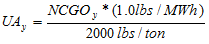
Where:
= unprorated allocation to a new
CAIR NO x unit.= converted gross electrical output or total
converted gross electrical output, as
applicable, for a new CAIR NO x unit.
5) The Agency will allocate CAIR NO x allowances from the NUSA to new CAIR NO x units as follows:
A) If the NUSA for the control period for which CAIR NO x allowances are requested has a number of allowances greater than or equal to the total unprorated allocations for all new units requesting allowances, the Agency will allocate the number of allowances using the unprorated allocation determined for that unit pursuant to subsection (d)(4) of this Section, to the extent that whole allowances may be allocated. For any additional allowances beyond this allocation of whole allowances, the Agency will retain the additional allowances in the NUSA for allocation pursuant to this Section in later control periods.
B) If the NUSA for the control period for which the allowances are requested has a number of CAIR NO x allowances less than the total unprorated allocation to all new CAIR NO x units requesting allocations, the Agency will allocate the available allowances for new CAIR NO x units on a pro-rata basis, using the unprorated allocation determined for that unit pursuant to subsection (d)(4) of this Section, to the extent that whole allowances may be allocated. For any additional allowances beyond this allocation of whole allowances, the Agency will retain the additional allowances in the NUSA for allocation pursuant to this Section in later control periods.
e) The Agency will review each NUSA allowance allocation request pursuant to subsection (b) of this Section. The Agency will accept a NUSA allowance allocation request only if the request meets, or is adjusted by the Agency as necessary to meet, the requirements of this Section.
f) By June 1 of the applicable control period, the Agency will notify each CAIR designated representative that submitted a NUSA allowance request of the amount of CAIR NO x allowances from the NUSA, if any, allocated for the control period to the new unit covered by the request.
g) The Agency will allocate CAIR NO x allowances to new units from the NUSA no later than October 31 of the applicable control period.
h) After a new CAIR NO x unit has operated in one control period, it becomes an existing unit for the purposes of calculating future allocations in Section 225.440 only, and the Agency will allocate CAIR NO x allowances for that unit, for the control period commencing five control periods after the control period in which the unit commences commercial operation, pursuant to Section 225.440. For example, if a unit commences commercial operation in 2009, in 2010, the Agency will allocate to that unit allowances pursuant to Section 225.440 for the 2014 control period. The new CAIR NO x unit will continue to receive CAIR NO x allowances from the NUSA according to this Section until the unit is eligible to use the CAIR NO x allowances allocated to the unit pursuant to Section 225.440.
i) If, after the completion of the procedures in subsection (c) of this Section for a control period, any unallocated CAIR NO x allowances remain in the NUSA for the control period, the Agency will, at a minimum, accrue those CAIR NO x allowances for future control period allocations to new CAIR NO x units. The Agency may from time to time elect to retire CAIR NO x allowances in the NUSA that are in excess of 15,881 for the purposes of continued progress toward attainment and maintenance of National Ambient Air Quality Standards pursuant to the CAA.
(Source: Added at 31 Ill. Reg. 12864, effective August 31, 2007)
Section 225.450 Monitoring, Recordkeeping and Reporting Requirements for Gross Electrical Output and Useful Thermal Energy
a) By January 1, 2008, or by the date of commencing commercial operation, whichever is later, the owner or operator of the CAIR NO x unit must operate a system for accurately measuring gross electrical output that is consistent with the requirements of either 40 CFR 60 or 75; must measure gross electrical output in MWh using such a system; and must record the output of the measurement system at all times. If a generator is served by two or more units, the information to determine each unit’s heat input for that control period must also be recorded, so as to allow each unit’s share of the gross electrical output to be determined. If heat input data is used, the owner or operator must comply with the applicable provisions of 40 CFR 75, as incorporated by reference in Section 225.140.
b) For a CAIR NO x unit that is a cogeneration unit, by January 1, 2008, or by the date the CAIR NO x unit commences to produce useful thermal energy, whichever is later, the owner or operator of the unit with cogeneration capabilities must install, calibrate, maintain, and operate meters for steam flow in lbs/hr, temperature in degrees Fahrenheit, and pressure in PSI, to measure and record the useful thermal energy that is produced, in mmBtu/hr, on a continuous basis. Owners and operators of a CAIR NO x unit that produces useful thermal energy but uses an energy transfer medium other than steam, e.g., hot water or glycol, must install, calibrate, maintain, and operate the necessary meters to measure and record the necessary data to express the useful thermal energy produced, in mmBtu/hr, on a continuous basis. If the CAIR NO x unit ceases to produce useful thermal energy, the owner or operator may cease operation of the meters, provided that operation of these meters must be resumed if the CAIR NO x unit resumes production of useful thermal energy.
c) The owner or operator of a CAIR NO x unit must either report gross electrical output data to the Agency or comply with the applicable provisions for providing heat input data to USEPA as follows:
1) By September 15, 2007, the gross electrical output for control periods 2001, 2002, 2003, 2004 and 2005, if available, and the unit’s useful thermal energy data, if applicable. If a generator is served by two or more units, the documentation needed to determine each unit’s share of the heat input of such units for that control period must also be submitted. If heat input data is used, the owner or operator must comply with the applicable provisions of 40 CFR 75, as incorporated by reference in Section 225.140.
2) By June 1, 2008, the gross electrical output for control periods 2006 and 2007, if available, and the unit’s useful thermal energy data, if applicable. If a generator is served by two or more units, the documentation needed to determine each unit’s share of the heat input of such units for that control period must also be submitted. If heat input data is used, the owner or operator must comply with the applicable provisions of 40 CFR 75, as incorporated by reference in Section 225.140.
d) Beginning with 2008, the CAIR designated representative of the CAIR NO x unit must submit to the Agency quarterly, by no later than April 30, July 31, October 31, and January 31 of each year, information for the CAIR NO x unit’s gross electrical output, on a monthly basis for the prior quarter, and, if applicable, the unit’s useful thermal energy for each month.
e) The owner or operator of a CAIR NO x unit must maintain on-site the monitoring plan detailing the monitoring system, maintenance of the monitoring system, including quality assurance activities pursuant to the requirements of 40 CFR 60 or 75, as applicable, including the appropriate provisions for the measurement of gross electrical output for the CAIR NO x Trading Program and, if applicable, for new units. The monitoring plan must include, but is not limited to:
1) A description of the system to be used for the measurement of gross electrical output pursuant to Section 225.450(a), including a list of any data logging devices, solid-state kW meters, rotating kW meters, electromechanical kW meters, current transformers, transducers, potential transformers, pressure taps, flow venturi, orifice plates, flow nozzles, vortex meters, turbine meters, pressure transmitters, differential pressure transmitters, temperature transmitters, thermocouples, resistance temperature detectors, and any equipment or methods used to accurately measure gross electrical output.
2) A certification statement by the CAIR designated representative that all components of the gross electrical output system have been tested to be accurate within three percent and that the gross electrical output system is accurate to within ten percent.
f) The owner or operator of a CAIR NO x unit must retain records for at least five years from the date the record is created or the data is collected under subsections (a) and (b) of this Section, and the reports are submitted to the Agency and USEPA in accordance with subsections (c) and (d) of this Section. The owner or operator of a CAIR NO x unit must retain the monitoring plan required in subsection (e) of this Section for at least five years from the date that it is replaced by a new or revised monitoring plan.
(Source: Added at 31 Ill. Reg. 12864, effective August 31, 2007)
Section 225.455 Clean Air Set-Aside (CASA)
a) A project sponsor may apply for allowances from the CASA for sponsoring an energy efficiency and conservation, renewable energy, or clean technology project as set forth in Section 225.460 by submitting the application required by Section 225.470.
b) Notwithstanding subsection (a) of this Section, a project sponsor with a CAIR NO x source that is out of compliance with this Subpart for a given control period may not apply for allowances from the CASA for that control period. If a source receives CAIR NO x allowances from the CASA and then is subsequently found to have been out of compliance with this Subpart for the applicable control period or periods, the project sponsor must restore the CAIR NO x allowances that it received pursuant to its CASA request or an equivalent number of CAIR NO x allowances to the CASA within six months after receipt of an Agency notice that NO x allowances must be restored. These allowances will be assigned to the fund from which they were distributed.
c) CAIR NO x allowances from the CASA will be allocated in accordance with the procedures in Section 225.475.
d) The project sponsor may submit an application that aggregates two or more projects under a CASA project category that would individually result in less than one allowance, but that equal at a minimum one whole allowance when aggregated.
(Source: Added at 31 Ill. Reg. 12864, effective August 31, 2007)
Section 225.460 Energy Efficiency and Conservation, Renewable Energy, and Clean
Technology Projects
a) Energy efficiency and conservation project means any of the following projects implemented and located in Illinois:
1) Demand side management projects that reduce overall power demand by using less energy include:
A) Smart building management software that more efficiently regulates power flows.
B) The use of or replacement to high efficiency motors, pumps, compressors, or steam systems.
C) Lighting retrofits.
2) Energy efficient new building construction projects include:
A) ENERGY STAR-qualified new home projects.
B) Measures to reduce or conserve energy consumption beyond the requirements of the Illinois Energy Conservation Code for Commercial Buildings [20 ILCS 687/6-3].
C) New residential construction projects that qualify for Energy Efficient Tax Incentives pursuant to the Energy Policy Act of 2005, (42 USC 15801 (2005)).
3) Supply-side energy efficiency projects include projects implemented to improve the efficiency in electricity generation by coal-fired power plants, and the efficiency of electrical transmission and distribution systems.
4) Highly efficient power generation projects, such as, but not limited to, combined cycle projects, combined heat and power, and microturbines. To be considered a highly efficient power generation project pursuant to this subsection (a)(4), a project must meet the following applicable thresholds and criteria:
A) For combined heat and power projects generating both electricity and useful thermal energy for space, water, or industrial process heat, a rated-energy efficiency of at least 60 percent and is not a CAIR NO x unit.
B) For combined cycle projects rated at greater than 0.50 MW, a rated-energy efficiency of at least 50 percent.
C) For microturbine projects rated at or below 0.50 MW and all other projects, a rated-energy efficiency of at least 40 percent.
b) Renewable energy project means any of the following projects implemented and located in Illinois:
1) Zero-emission electric generating projects, including wind, solar (thermal or photovoltaic), and hydropower projects. Eligible hydropower plants are restricted to new generators, that are not replacements of existing generators, that commenced operation on or after January 1, 2006, and that do not involve the significant expansion of an existing dam or the construction of a new dam.
2) Renewable energy units are those units that generate electricity using more than 50 percent of the heat input, on an annual basis, from dedicated crops grown for energy production or the capture systems for methane gas from landfills, water treatment plants or sewage treatment plants, and organic waste biomass, and other similar sources of non-fossil fuel energy. Renewable energy projects do not include energy from incineration by burning or heating of waste wood, tires, garbage, general household waste, institutional lunchroom waste, office waste, landscape waste, or construction or demolition debris.
c) Clean technology project for reducing emissions from producing electricity and useful thermal energy means any of the following projects implemented and located in Illinois:
1) Air pollution control equipment upgrades at existing coal-fired EGUs, as follows: installation of flue gas desulfurization (FGD) for control of SO 2 emissions; installation of a baghouse for control of particulate matter emissions; and installation of selective catalytic reduction (SCR), selective non-catalytic reduction (SNCR), or other add-on control devices for control of NO x emissions. For this purpose, a unit will be considered “existing” after it has been in commercial operation for at least eight years. Air pollution control upgrade projects do not include the addition of low NO x burners, overfired air techniques or gas reburning techniques for control of NO x emissions; projects involving flue gas conditioning techniques or upgrades, or replacement of electrostatic precipitators; or addition of an activated carbon injection or other sorbent injection system for control of mercury.
2) Clean coal technologies projects include:
A) Integrated gasification combined cycle (IGCC) plants.
B) Fluidized bed coal combustion that commenced operation prior to December 31, 2006.
d) In addition to those projects excluded in subsections (a) through (c) of this Section, the following projects are also not energy efficiency and conservation, renewable energy, or clean technology projects:
1) Nuclear power projects.
2) Projects required to meet emission standards or technology requirements under State or federal law or regulation, except that allowances may be allocated for:
A) The installation of a baghouse.
B) Projects undertaken pursuant to Section 225.233 or Subpart F.
3) Projects used to meet the requirements of a court order or consent decree, except that allowances may be allocated for:
A) Emission rates or limits achieved that are lower than what is required to meet the emission rates or limits for SO 2 or NO x, or for installing a baghouse as provided for in a court order or consent decree entered into before May 30, 2006.
B) Projects used to meet the requirements of a court order or consent decree entered into on or after May 30, 2006, if the court order or consent decree does not specifically preclude such allocations.
4) A Supplemental Environmental Project (SEP).
e) Applications for projects implemented and located in Illinois that are not specifically listed in subsections (a) through (c) of this Section, and that are not specifically excluded by definition in subsections (a) through (c) of this Section or by specific exclusion in subsection (d) of this Section, may be submitted to the Agency. The application must designate which category or categories from those listed in subsections (a)(1) through (c)(2)(B) of this Section best fit the proposed project and the applicable formula pursuant to Section 225.465(b) to calculate the number of allowances that it is requesting. The Agency will determine whether the application is approvable based on a sufficient demonstration by the project sponsor that the project is a new type of energy efficiency, renewable energy, or clean technology project, similar in its effects as the projects specifically listed in subsections (a) through (c)(2)(B) of this Section.
f) Early adopter projects include projects that meet the criteria for any energy efficiency and conservation, renewable energy, or clean technology projects listed in subsections (a), (b), (c), and (e) of this Section and commence construction between July 1, 2006 and December 31, 2012.
(Source: Added at 31 Ill. Reg. 12864, effective August 31, 2007)
Section 225.465 Clean Air Set-Aside (CASA) Allowances
a) The CAIR NO x allowances for the CASA for each control period will be assigned to the following categories of projects:
Phase I Phase II
(2009-2014) (2015 and thereafter)
1) Energy Efficiency and Conservation/ 9149 7625
Renewable Energy
2) Air Pollution Control Equipment 3811 3175
Upgrades
3) Clean Coal Technology 4573 3810
4) Early Adopters 1525 1271
b) The following formulas must be used to determine the number of CASA allowances that may be allocated to a project per control period:
1) For an energy efficiency and conservation project pursuant to Section 225.460(a)(1) through (a)(4)(A), the number of allowances must be calculated using the number of megawatt hours of electricity that was not consumed during a control period and the following formula:
A = (MWh c ) ´ (1.5 lb/MWh) / 2000 lb
Where:
A = The number of allowances for a particular project.
MWh c = The number of megawatt hours of electricity
conserved or generated during a control period by a
project.
2) For a zero emission electric generating project pursuant to Section 225.460(b)(1), the number of allowances must be calculated using the number of megawatt hours of electricity generated during a control period and the following formula:
A = (MWh g ) ´ (2.0 lb/MWh) / 2000 lb
Where:
A = The number of allowances for a particular project
MWh g = The number of megawatt hours of electricity
generated during a control period by a project.
3) For a renewable energy emission unit pursuant to Section 225.460(b)(2), the number of allowances must be calculated using the number of MWhs of electricity generated during a control period and the following formula:
A = (MWh g ) ´ (0.5 lb/MWh) / 2000 lb
Where:
A = The number of allowances for a particular project.
MWh g = The number of MW hours of electricity generated
during a control period by a project.
4) For an air pollution control equipment upgrade project pursuant to Section 225.460(c)(1), the number of allowances will be calculated as follows:
A) For NO x or SO 2 control projects, by determining the difference in emitted NO x or SO 2 per control period using the emission rate before and after replacement or improvement, and the following formula:
A= (MWh g ) ´ K ´ (ER B lb/MWh - ER A lb/MWh) / 2000 lb
Where:
A = The number of allowances for a particular
project.
MWh g = The number of megawatt hours of electricity
generated during a control period by a
project.
K = The pollutant factor: for NO x , K= 0.1; and
for SO 2 , K = 0.05.
ER B = Average NO x or SO 2 emission rate based on
CEMS data from the most recent two
control periods prior to the replacement or
improvement of the control equipment in
lb/MWh, unless subject to a court order
or consent decree. For units subject to a
court order or consent decree entered into before May 30, 2006, ER B is limited to emission rates that are lower than the emission rate required in the consent decree or court order. For a court order or consent decree entered into after May 30, 2006, ER B is limited to the lesser of the emission rate specified in the court order or consent decree or the actual average emission rate during the control period. If such limit is not expressed in lb/MWh, the limit must be converted into lb/MWh using a heat rate of 10 mmBtu/1 MW.
ER A = Annual NO x or SO 2 average emission rate
for the applicable control period data based
on CEMS data in lb/MWh.
B) For a baghouse project:
A = (MWh g ) ´ (Q lb/MWh) / 2000 lb
Where:
A = The number of allowances for a
particular project.
MWh g = The number of MWh of
electricity generated during a control period
or the portion of a control period that the
units were controlled by the baghouse.
Q =
1) If a baghouse was not installed pursuant to a consent decree or court order, Q shall equal 0.2.
2) If a baghouse was installed pursuant to a consent decree or court order that assigns a Q factor, then Q equals the factor established in the consent decree or court order but must not exceed a factor of 0.2.
3) If a baghouse was installed pursuant to a consent decree or court order that does not assign a Q factor then Q shall equal:
Q= 0.25 – (P x ER q )
Where:
P = If the most recent control period’s average PM emission rate was based on PM CEMS data, P equals 1.0; otherwise P = 1.1.
ER q = The magnitude of most recent control period’s average PM emission rate in lb/MWh exiting the baghouse, subject to the following limits:
If P = 1.0, then 1/10 ≤ ER q ≤ 2/10
If P = 1.1, then 1/11 ≤ ER q ≤ 2/11
If the ER q is less than the lower limit, the lower limit shall be used.
If ER q is greater than the upper limit, the upper limit shall be used.
If ER q is not expressed in lb/MWh, the number must be converted to lb/MWh using a heat rate of 10 mmBtu/1 MW.
5) For highly efficient power generation and clean coal technology projects:
A) For projects other than fluidized coal combustion pursuant to Section 225.460(a)(4)(B), (a)(4)(C), and (c)(2), the number of allowances must be calculated using the number of MWh of electricity the project generates during a control period and the following formula:
A = (MWh g ) ´ (1.0 lb/MWh – ER lb/MWh) / 2000 lb
Where:
A = The number of allowances for a particular
project.
MWh g = The number of megawatt hours of electricity
generated during a control period by a
project.
ER = Annual average NO x emission rate based on
CEMS data in 1b/MWh.
B) For fluidized bed coal combustion projects pursuant to Section 225.460 (c)(2), the number of allowances shall be calculated using the number of gross MWh of electricity the project generates during a control period and the following formula:
A = (MWh g ) x (1.4 lb/MWh – ER lb/MWh) / 2000 lb
Where:
A = The number of allowances for a particular project.
MWh g = The number of gross MWh of electricity generated during a control period by a project.
ER = Annual NO x emission rate for the control
period based on CEMS data in lb/MWh.
6) For a CASA project that commences construction before December 31, 2012, in addition to the allowances allocated pursuant to subsections (b)(1) through (b)(5) of this Section, a project sponsor may also request additional allowances pursuant to the early adopter project category pursuant to Section 225.460(e) based on the following formula:
A = 1.0 + 0.10 ´ Σ A i
Where:
A = The number of allowances for a particular project as
determined in subsections (b)(1) through (b)(5) of
this Section.
A i = The number of allowances as determined in
subsection (b)(1), (b)(2), (b)(3), (b)(4) or (b)(5) of
this Section for a given project.
(Source: Added at 31 Ill. Reg. 12864, effective August 31, 2007)
Section 225.470 Clean Air Set-Aside (CASA) Applications
a) A project sponsor may request allowances if the project commenced construction on or after the dates listed in this subsection. The project sponsor may request and be allocated allowances from more than one CASA category for a project, if applicable.
1) Demand side management, energy efficient new construction, and supply side energy efficiency and conservation projects that commenced construction on or after January 1, 2003;
2) Fluidized bed coal combustion projects, highly efficient power generation operations projects, or renewable energy emission units, that commenced construction on or after January 1, 2001; and
3) All other projects on or after July 1, 2006.
b) Beginning with the 2009 control period and each control period thereafter, a project sponsor may request allowances from the CASA. The application must be submitted to the Agency by May 1 of the control period for which the allowances are being requested.
c) The allocation will be based on the electricity conserved or generated in the control period preceding the calendar year in which the application is submitted. To apply for a CAIR NO x allocation from the CASA, project sponsors must provide the Agency with the following information:
1) Identification of the project sponsor, including name, address, type of organization, certification that the project sponsor has met the definition of “project sponsor” as set forth in Section 225.130,and names of the principals or corporate officials.
2) The number of the CAIR NO x general or compliance account for the project and the name of the associated CAIR account representative.
3) A description of the project or projects, location, the role of the project sponsor in the projects, and a general explanation of how the amount of energy conserved or generated was measured, verified, and calculated, and the number of allowances requested with the supporting calculations. The number of allowances requested will be calculated using the applicable formula from Section 225.470(b).
4) Detailed information to support the request for allowances, including the following types of documentation for the measurement and verification of the NO x emissions reductions, electricity generated, or electricity conserved using established measurement verification procedures, as applicable. The measurement and verification required will depend on the type of project proposed.
A) As applicable, documentation of the project’s base and control period conditions and resultant base and control period energy data, using the procedures and methods included in M&V Guidelines: Measurement and Verification for Federal Energy Projects, incorporated by reference in Section 225.140, or other method approved by the Agency. Examples include:
i) Energy consumption and demand profiles;
ii) Occupancy type;
iii) Density and periods;
iv) Space conditions or plant throughput for each operating period and season. (for example, in a building this would include the light level and color, space temperature, humidity and ventilation);
v) Equipment inventory, nameplate data, location, and condition; and
vi) Equipment operating practices (schedules and set points, actual temperatures/pressures);
B) Emissions data, including, if applicable, CEMS data;
C) Information for rated-energy efficiency, including supporting documentation and calculations; and
D) Electricity, in MWh generated or conserved for the applicable control period.
5) Notwithstanding the requirements of subsection (c)(4) of this Section, applications for fewer than five allowances may propose other reliable and applicable methods of quantification acceptable to the Agency.
6) Any additional information requested by the Agency to determine the correctness of the requested number of allowances, including site information, project specifications, supporting calculations, operating procedures, and maintenance procedures.
7) The following certification by the responsible official for the project sponsor and the applicable CAIR account representative for the project:
“I am authorized to make this submission on behalf of the project sponsor and the holder of the CAIR NO x general account or compliance account for which the submission is made. I certify under penalty of law that I have personally examined, and am familiar with, the statements and information submitted in this application and all its attachments. Based on my inquiry of those individuals with primary responsibility for obtaining the information, I certify that the statements and information are to the best of my knowledge and belief true, accurate, and complete. I am aware that there are significant penalties for submitting false statements and information or omitting required statements and information.”
d) A project sponsor may request allowances from the CASA for each project for a total number of control periods not to exceed the number of control periods listed in this subsection. After a project has been allocated allowances from the CASA, subsequent requests for the project from the project sponsor must include the information required by subsections (c)(1), (c)(2), (c)(3) and (c)(7) of this Section, a description of any changes, or further improvements made to the project, and information specified in subsections (c)(5) and (c)(6) as specifically requested by the Agency.
1) For energy efficiency and conservation projects (except for efficient operation and renewable energy projects), for a total of eight control periods.
2) For early adopter projects, for a total of ten control periods.
3) For air pollution control equipment upgrades, for a total of 15 control periods.
4) For renewable energy projects, clean coal technology, and highly efficient power generation projects, for each year that the project is in operation.
e) A project sponsor must keep copies of all CASA applications and the documentation used to support the application for at least five years.
(Source: Added at 31 Ill. Reg. 12864, effective August 31, 2007)
Section 225.475 Agency Action on Clean Air Set-Aside (CASA) Applications
a) By September 1, 2009 and each September 1 thereafter, the Agency will determine the total number of allowances that are approvable for allocation to project sponsors based upon the applications submitted pursuant to Section 225.470.
1) The Agency will determine the number of CAIR NO x allowances that are approvable based on the formulas and the criteria for these projects. The Agency will notify a project sponsor within 90 days after receipt of an application if the project is not approvable, the number of allowances requested is not approvable, or additional information is needed by the Agency to complete its review of the application.
2) If the total number of CAIR NO x allowances requested for approved projects is less than or equal to the number of CAIR NO x allowances in the CASA project category, the number of allowances that are approved will be allocated to each CAIR NO x compliance or general account.
3) If more CAIR NO x allowances are requested than the number of CAIR NO x allowances in a given CASA project category, allowances will be allocated on a pro-rata basis based on the number of allowances available, subject to further adjustment as provided for by subsection (b) of this Section. CAIR NO x allowances will be allocated, transferred, or used as whole allowances. The number of whole allowances will be determined by rounding down for decimals less than 0.5 and rounding up for decimals of 0.5 or greater.
b) For control periods 2011 and thereafter:
1) If there are, after the completion of the procedures in subsection (a) of this Section for a control period, any CAIR NO x allowances not allocated to a CASA project for the control period the remaining allowances will accrue in each CASA project category up to twice the number of allowances that are assigned to the project category each control period as set forth in Section 225.465.
2) If any allowances remain after allocations pursuant to subsection (b)(1) of this Section, the Agency will allocate these allowances pro rata to projects that received fewer allowances than requested, based on the number of allowances not allocated but approved by the Agency for the project under CASA. No project may be allocated more allowances than approved by the Agency for the applicable control period.
3) If any allowances remain after the allocation of allowances pursuant to subsection (b)(2) of this Section, the Agency will then distribute pro-rata the remaining allowances to project categories that have fewer than twice the number of allowances assigned to that project category. The pro-rata distribution will be based on the difference between two times the project category and the number of allowances that remain in the project category.
4) If allowances still remain undistributed after the allocations and distributions in the subsections (b)(1) through (b)(3) are completed, the Agency may elect to retire the CAIR NO x allowances that have not been distributed to any CASA category to continue progress toward attainment or maintenance of the National Ambient Air Quality Standards pursuant to the CAA.
(Source: Added at 31 Ill. Reg. 12864, effective August 31, 2007)
Section 225.480 Compliance Supplement Pool
In addition to the CAIR NO x allowances allocated pursuant to Section 225.425, the USEPA has allowed allocation of an additional 11,299 CAIR NO x allowances in Illinois as a compliance supplement pool to Illinois for the control period in 2009. However, for the purposes of public health and air quality improvements, none of these allowances will be allocated.
(Source: Added at 31 Ill. Reg. 12864, effective August 31, 2007)
SUBPART E: CAIR NO x OZONE SEASON TRADING PROGRAM
Section 225.500 Purpose
The purpose of this Subpart E is to control the seasonal emissions of nitrogen oxides (NO x ) from EGUs by determining allocations and implementing the CAIR NO x Ozone Season Trading Program.
(Source: Added at 31 Ill. Reg. 12864, effective August 31, 2007)
Section 225.505 Applicability
a) Except as provided in subsections (b)(1), (b)(3), and (b)(4) of this Section:
1) The following units are CAIR NO x Ozone Season units, and any source that includes one or more such units is a CAIR NO x source subject to the requirements of this Subpart E: any stationary, fossil-fuel-fired boiler or stationary, fossil-fuel-fired combustion turbine serving at any time, since the later of November 15, 1990 or the start-up of the unit’s combustion chamber, a generator with nameplate capacity of more than 25 MWe producing electricity for sale.
2) If a stationary boiler or stationary combustion turbine that, pursuant to subsection (a)(1) of this Section, is not a CAIR NO x Ozone Season unit begins to combust fossil fuel or to serve a generator with nameplate capacity of more than 25 MWe producing electricity for sale, the unit will become a CAIR NO x Ozone Season unit as provided in subsection (a)(1) of this Section on the first date on which it both combusts fossil fuel and serves such generator.
b) The units that meet the requirements set forth in subsections (b)(1), (b)(3), and (b)(4) of this Section will not be CAIR NO x Ozone Season units and units that meet the requirements of subsections (b)(2) and (b)(5) of this Section are CAIR NO x Ozone Season units:
1) Any unit that would otherwise be classified as a CAIR NO x Ozone Season unit pursuant to subsection (a)(1) or (a)(2) of this Section and:
A) Qualifies as a cogeneration unit during the 12-month period starting on the date the unit first produces electricity and continues to qualify as a cogeneration unit; and
B) Does not serve at any time, since the later of November 15, 1990 or the start-up of the unit’s combustion chamber, a generator with nameplate capacity of more than 25 MWe supplying any calendar year more than one-third of the unit’s potential electric output capacity or 219,000 MWh, whichever is greater, to any utility power distribution for sale.
2) If a unit qualifies as a cogeneration unit during the 12-month period starting on the date the unit first produces electricity and meets the requirements of subsection (b)(1) of this Section for at least one calendar year, but subsequently no longer meets all such requirements, the unit shall become a CAIR NO x Ozone Season unit starting on the earlier of January 1 after the first calendar year during which the unit no longer qualifies as a cogeneration unit or January 1 after the first calendar year during which the unit no longer meets the requirements of subsection (b)(1)(B) of this Section.
3) Any unit that would otherwise be classified as a CAIR NO x Ozone Season unit pursuant to subsection (a)(1) or (a)(2) of this Section commencing operation before January 1, 1985 and:
A) Qualifies as a solid waste incineration unit; and
B) Has an average annual fuel consumption of non-fossil fuel for 1985-1987 exceeding 80 percent (on a Btu basis) and an average annual fuel consumption of non-fossil fuel for any three consecutive calendar years after 1990 exceeding 80 percent (on a Btu basis).
4) Any unit that would otherwise be classified as a CAIR NO x Ozone Season unit under subsection (a)(1) or (a)(2) of this Section commencing operation on or after January 1, 1985 and:
A) Qualifies as a solid waste incineration unit; and
B) Has an average annual fuel consumption of non-fossil fuel the first three years of operation exceeding 80 percent (on a Btu basis) and an average annual fuel consumption of non-fossil fuel for any three consecutive calendar years after 1990 exceeding 80 percent (on a Btu basis).
5) If a unit qualifies as a solid waste incineration unit and meets the requirements of subsection (b)(3) or (b)(4) of this Section for at least three consecutive years, but subsequently no longer meets all such requirements, the unit shall become a CAIR NO x Ozone Season unit starting on the earlier of January 1 after the first three consecutive calendar years after 1990 for which the unit has an average annual fuel consumption of 20 percent or more.
(Source: Added at 31 Ill. Reg. 12864, effective August 31, 2007)
Section 225.510 Compliance Requirements
a) The designated representative of a CAIR NO x Ozone Season unit must comply with the requirements of the CAIR NO x Ozone Season Trading Program for Illinois as set forth in this Subpart E and 40 CFR 96, subpart AAAA (CAIR NO x Ozone Season Trading Program General Provisions) (excluding 40 CFR 96.304, 96.305(b)(2), and 96.306); 40 CFR 96, subpart BBBB (CAIR Designated Representative for CAIR NO x Ozone Season Sources); 40 CFR 96, subpart FFFF (CAIR NO x Ozone Season Allowance Tracking System); 40 CFR 96, subpart GGGG (CAIR NO x Ozone Season Allowance Transfers); and 40 CFR 96, subpart HHHH (Monitoring and Reporting); as incorporated by reference in Section 225.140.
b) Permit requirements:
1) The designated representative of each source with one or more CAIR NO x Ozone Season units at the source must apply for a permit issued by the Agency with federally enforceable conditions covering the CAIR NO x Ozone Season Trading Program (“CAIR permit”) that complies with the requirements of Section 225.520 (Permit Requirements).
2) The owner or operator of each CAIR NO x Ozone Season source and each CAIR NO x Ozone Season unit at the source must operate the CAIR NO x Ozone Season unit in compliance with its CAIR permit.
c) Monitoring requirements:
1) The owner or operator of each CAIR NO x Ozone Season source and each CAIR NO x Ozone Season unit at the source must comply with the monitoring, reporting and recordkeeping requirements of 40 CFR 96, subpart HHHH; 40 CFR 75; and Section 225.550. The CAIR designated representative of each CAIR NO x Ozone Season source and each CAIR NO x Ozone Season unit at the source must comply with those sections of the monitoring, reporting and recordkeeping requirements of 40 CFR 96, subpart HHHH, applicable to a CAIR designated representative.
2) The compliance of each CAIR NO x Ozone Season source with the CAIR NO x Ozone Season emissions limitation pursuant to subsection (d) of this Section will be determined by the emissions measurements recorded and reported in accordance with 40 CFR 96, subpart HHHH.
d) Emission requirements:
1) By the allowance transfer deadline, midnight of November 30, 2009, and by midnight of November 30 of each subsequent year if November 30 is a business day, the owner or operator of each CAIR NO x Ozone Season source and each CAIR NO x Ozone Season unit at the source must hold allowances available for compliance deductions pursuant to 40 CFR 96.354(a) in the CAIR NO x Ozone Season source’s compliance account. If November 30 is not a business day, the allowance transfer deadline means by midnight of the first business day thereafter. The number of allowances held may not be less than the tons of NO x emissions for the control period from all CAIR NO x Ozone Season units at the CAIR NO x Ozone Season source, as determined in accordance with 40 CFR 96, subpart HHHH.
2) Each ton of excess emissions of a CAIR NO x Ozone Season source for each day in a control period, starting in 2009 will constitute a separate violation of this Subpart E, the Act, and the CAA.
3) Each CAIR NO x Ozone Season unit will be subject to the requirements of subsection (d)(1) of this Section for the control period starting on the later of May 1, 2009 or the deadline for meeting the unit’s monitoring certification requirements pursuant to 40 CFR 96.370(b)(1), (b)(2) or (b)(3) and for each control period thereafter.
4) CAIR NO x Ozone Season allowances must be held in, deducted from, or transferred into or among allowance accounts in accordance with this Subpart and 40 CFR 96, subparts FFFF and GGGG.
5) In order to comply with the requirements of subsection (d)(1) of this Section, a CAIR NO x Ozone Season allowance may not be deducted for compliance according to subsection (d)(1) of this Section, for a control period in a calendar year before the year for which the CAIR NO x Ozone Season allowance is allocated.
6) A CAIR NO x Ozone Season allowance is a limited authorization to emit one ton of NO x in accordance with the CAIR NO x Ozone Season Trading Program. No provision of the CAIR NO x Ozone Season Trading Program, the CAIR permit application, the CAIR permit, or a retired unit exemption pursuant to 40 CFR 96.305, and no provision of law, will be construed to limit the authority of the United States or the State to terminate or limit this authorization.
7) A CAIR NO x Ozone Season allowance does not constitute a property right.
8) Upon recordation by USEPA pursuant to 40 CFR 96, subpart FFFF or GGGG, every allocation, transfer, or deduction of a CAIR NO x Ozone Season allowance to or from a CAIR NO x Ozone Season source compliance account is deemed to amend automatically, and become a part of, any CAIR permit of the CAIR NO x Ozone Season source. This automatic amendment of the CAIR permit will be deemed an operation of law and will not require any further review.
e) Recordkeeping and reporting requirements:
1) Unless otherwise provided, the owner or operator of the CAIR NO x Ozone Season source and each CAIR NO x Ozone Season unit at the source must keep on site at the source each of the documents listed in subsections (e)(1)(A) through (e)(1)(E) of this Section for a period of five years from the date the document is created. This period may be extended for cause, at any time prior to the end of five years, in writing by the Agency or USEPA.
A) The certificate of representation for the CAIR designated representative for the source and each CAIR NO x Ozone Season unit at the source, all documents that demonstrate the truth of the statements in the certificate of representation, provided that the certificate and documents must be retained on site at the source beyond such five-year period until the documents are superseded because of the submission of a new certificate of representation, pursuant to 40 CFR 96.313, changing the CAIR designated representative.
B) All emissions monitoring information, in accordance with 40 CFR 96, subpart HHHH.
C) Copies of all reports, compliance certifications, and other submissions and all records made or required pursuant to the CAIR NO x Ozone Season Trading Program or documents necessary to demonstrate compliance with the requirements of the CAIR NO x Ozone Season Trading Program or with the requirements of this Subpart E.
D) Copies of all documents used to complete a CAIR permit application and any other submission or documents used to demonstrate compliance pursuant to the CAIR NO x Ozone Season Trading Program.
E) Copies of all records and logs for gross electrical output and useful thermal energy required by Section 225.550.
2) The CAIR designated representative of a CAIR NO x Ozone Season source and each CAIR NO x Ozone Season unit at the source must submit to the Agency and USEPA the reports and compliance certifications required pursuant to the CAIR NO x Ozone Season Trading Program, including those pursuant to 40 CFR 96, subpart HHHH and Section 225.550.
f) Liability:
1) No revision of a permit for a CAIR NO x Ozone Season unit may excuse any violation of the requirements of this Subpart E or the requirements of the CAIR NO x Ozone Season Trading Program.
2) Each CAIR NO x Ozone Season source and each CAIR NO x Ozone Season unit must meet the requirements of the CAIR NO x Ozone Season Trading Program.
3) Any provision of the CAIR NO x Ozone Season Trading Program that applies to a CAIR NO x Ozone Season source (including any provision applicable to the CAIR designated representative of a CAIR NO x Ozone Season source) will also apply to the owner and operator of the CAIR NO x Ozone Season source and to the owner and operator of each CAIR NO x Ozone Season unit at the source.
4) Any provision of the CAIR NO x Ozone Season Trading Program that applies to a CAIR NO x Ozone Season unit (including any provision applicable to the CAIR designated representative of a CAIR NO x Ozone Season unit) will also apply to the owner and operator of the CAIR NO x Ozone Season unit.
5) The CAIR designated representative of a CAIR NO x Ozone Season unit that has excess emissions in any control period must surrender the allowances as required for deduction pursuant to 40 CFR 96.354(d)(1).
6) The owner or operator of a CAIR NO x Ozone Season unit that has excess NO x emissions in any control period must pay any fine, penalty, or assessment or comply with any other remedy imposed pursuant to the Act and 40 CFR 96.354(d)(2).
g) Effect on other authorities: No provision of the CAIR NO x Ozone Season Trading Program, a CAIR permit application, a CAIR permit, or a retired unit exemption pursuant to 40 CFR 96.305 will be construed as exempting or excluding the owner and operator and, to the extent applicable, the CAIR designated representative of a CAIR NO x Ozone Season source or a CAIR NO x Ozone Season unit from compliance with any other regulation promulgated pursuant to the CAA, the Act, any State regulation or permit, or a federally enforceable permit.
(Source: Added at 31 Ill. Reg. 12864, effective August 31, 2007)
Section 225.515 Appeal Procedures
The appeal procedures for decisions of USEPA pursuant to the CAIR NO x Ozone Season Trading Program are set forth in 40 CFR 78, as incorporated by reference in Section 225.140.
(Source: Added at 31 Ill. Reg. 12864, effective August 31, 2007)
Section 225.520 Permit Requirements
a) Permit requirements:
1) The owner or operator of each source with a CAIR NO x Ozone Season unit is required to submit:
A) A complete permit application addressing all applicable CAIR NO x Ozone Season Trading Program requirements for a permit meeting the requirements of this Section, applicable to each CAIR NO x Ozone Season unit at the source. Each CAIR permit must contain elements required for a complete CAIR permit application pursuant to subsection (b)(2) of this Section.
B) Any supplemental information that the Agency determines necessary in order to review a CAIR permit application and issue any CAIR permit.
2) Each CAIR permit will be issued pursuant to Sections 39 and 39.5 of the Act and will contain federally enforceable conditions addressing all applicable CAIR NO x Ozone Season Trading Program requirements and will be a complete and segregable portion of the source’s entire permit pursuant to subsection (a)(1) of this Section.
3) No CAIR permit may be issued until the Agency and USEPA have received a complete certificate of representation for a CAIR designated representative pursuant to 40 CFR 96, subpart BBBB, for the CAIR NO x Ozone Season source and the CAIR NO x Ozone Season unit at the source.
4) For all CAIR NO x Ozone Season units that commenced operation before December 31, 2007, the owner or operator of the unit must submit a CAIR permit application meeting the requirements of this Section on or before December 31, 2007.
5) For all units that commence operation on or after December 31, 2007, the owner or operator of these units must submit applications for construction and operating permits pursuant to the requirements of Sections 39 and 39.5 of the Act, as applicable, and 35 Ill. Adm. Code 201, and the applications must specify that they are applying for CAIR permits and must address the CAIR permit application requirements of this Section 225.520.
b) Permit applications:
1) Duty to apply: The owner or operator of any source with one or more CAIR NO x Ozone Season units must submit to the Agency a CAIR permit application for the source covering each CAIR NO x Ozone Season unit pursuant to subsection (b)(2) of this Section by the applicable deadline in subsection (a)(4) or (a)(5) of this Section. The owner or operator of any source with one or more CAIR NO x Ozone Season units must reapply for a CAIR permit for the source as required by this Subpart, 35 Ill. Adm. Code 201, and, as applicable, Sections 39 and 39.5 of the Act.
2) Information requirements for CAIR permit applications. A complete CAIR permit application must include the following elements concerning the source for which the application is submitted:
A) Identification of the source, including plant name. The ORIS (Office of Regulatory Information Systems) or facility code assigned to the source by the Energy Information Administration must also be included, if applicable;
B) Identification of each CAIR NO x Ozone Season unit at the source; and
C) The compliance requirements applicable to each CAIR NO x Ozone Season unit as set forth in Section 225.510.
3) An application for a CAIR permit will be treated as a modification of the CAIR NO x Ozone Season source’s existing federally enforceable permit, if such a permit has been issued for that source, and will be subject to the same procedural requirements. When the Agency issues a CAIR permit pursuant to the requirements of this Section, it will be incorporated into and become part of that source’s existing federally enforceable permit.
c) Permit content: Each CAIR permit is deemed to incorporate automatically the definitions and terms specified in Section 225.130 and 40 CFR 96.302, as incorporated by reference in Section 225.140, and, upon recordation of USEPA under 40 CFR 96, subparts FFFF and GGGG, as incorporated by reference in Section 225.140, every allocation, transfer, or deduction of a CAIR NO x Ozone Season allowance to or from the compliance account of the CAIR NO x Ozone Season source covered by the permit.
(Source: Added at 31 Ill. Reg. 12864, effective August 31, 2007)
Section 225.525 Ozone Season Trading Budget
The CAIR NO x Ozone Season Trading budget available for allowance allocations for each control period will be determined as follows:
a) The total base CAIR NO x Ozone Season Trading budget is 30,701 tons per control period for the years 2009 through 2014, subject to a reduction for two set-asides, the NUSA and the CASA. Five percent of the budget will be allocated to the NUSA and 25 percent will be allocated to the CASA, resulting in a CAIR NO x Ozone Season Trading budget available for allocation of 21,491 tons per control period pursuant to Section 225.540. The requirements of the NUSA are set forth in Section 225.545, and the requirements of the CASA are set forth in Sections 225.555 through 225.570.
b) The total base CAIR NO x Ozone Season Trading budget is 28,981 tons per control period for the year 2015 and thereafter, subject to a reduction for two set-asides, the NUSA and the CASA. Five percent of the budget will be allocated to the NUSA and 25 percent will be allocated to the CASA, resulting in a CAIR NO x Ozone Season Trading budget available for allocation of 20,287 tons per control period pursuant to Section 225.540.
c) If USEPA adjusts the total base CAIR NO x Ozone Season Trading budget for any reason, the Agency will adjust the base CAIR NO x Ozone Season Trading budget and the CAIR NO x Ozone Season Trading budget available for allocation, accordingly.
(Source: Added at 31 Ill. Reg. 12864, effective August 31, 2007)
Section 225.530 Timing for Ozone Season Allocations
a) On or before September 25, 2007, the Agency will submit to USEPA the CAIR NO x Ozone Season allowance allocations, in accordance with Sections 225.535 and 225.540, for the 2009, 2010, and 2011 control periods.
b) By July, 2008 and July 31 of each year thereafter, the Agency will submit to USEPA the CAIR NO x Ozone Season allowance allocations in accordance with Sections 225.535 and 225.540, for the control period four years after the year of the applicable deadline for submission pursuant to this Section. For example, on July 31, 2008, the Agency will submit to USEPA the allocation for the 2012 control period.
c) For CAIR NO x Ozone Season units that commence commercial operation on or after May 1, 2006, that have not been allocated allowances under Section 225.440 for the applicable or any preceding control period, the Agency will allocate allowances from the NUSA in accordance with Section 225.545. The Agency will report these allocations to USEPA by July 31 of the applicable control period. For example, on July 31, 2009, the Agency will submit to USEPA the allocations from the NUSA for the 2009 control period.
d) The Agency will allocate allowances from the CASA to energy efficiency, renewable energy, and clean technology projects pursuant to the criteria in Sections 225.555 through 225.570. The Agency will report these allocations to USEPA by October 1 of each year. For example, on October 1, 2009, the Agency will submit to USEPA the allocations from the CASA for the 2009 control period, based on reductions made in the 2008 control period.
(Source: Added at 31 Ill. Reg. ________________, effective ______________)
Section 225.535 Methodology for Calculating Ozone Season Allocations
The Agency will calculate converted gross electrical output (CGO), in MWh, for each CAIR NO x Ozone Season unit that has operated during at least one control period prior to the calendar year in which the Agency reports the allocations to USEPA as follows:
a) For control periods 2009, 2010, and 2011, the owner or operator of the unit must submit in writing to the Agency, by September 15, 2007, a statement that either gross electrical output data or heat input data is to be used to calculate converted gross electrical output. The data shall be used to calculate converted gross electrical output pursuant to either subsection (a)(1) or (a)(2) of this Section:
1) Gross electrical output: If the unit has four or five control periods of data, then the gross electrical output (GO) will be the average of the unit’s three highest gross electrical outputs from the 2001, 2002, 2003, 2004, or 2005 control periods. If the unit has three or fewer control periods of gross electrical outputs, the gross electrical output will be the average of those control periods for which data is available. If a generator is served by two or more units, then the gross electrical output of the generator will be attributed to each unit in proportion to the unit’s share of the total control period heat input of these units for the control period. The unit’s converted gross electrical output will be calculated as follows:
A) If the unit is coal-fired:
CGO (in MWh) = GO (in MWh) ´ 1.0;
B) If the unit is oil-fired:
CGO (in MWh) = GO (in MWh) ´ 0.6; or
C) If the unit is neither coal-fired nor oil-fired:
CGO (in MWh) = GO (in MWh) ´ 0.4.
2) Heat input (HI): If the unit has four or five control periods of data, the average of the unit’s three highest control period heat inputs from 2001, 2002, 2003, 2004, or 2005 will be used. If the unit has three or fewer control periods of heat input data, the heat input will be the average of those control periods for which data is available. The unit’s converted gross electrical output will be calculated as follows:
A) If the unit is coal-fired:
CGO (in MWh) = HI (in mmBtu) ´ 0.0967;
B) If the unit is oil-fired:
CGO (in MWh) = HI (in mmBtu) ´ 0.0580; or
C) If the unit is neither coal-fired nor oil-fired:
CGO (in MWh) = HI (in mmBtu) ´ 0.0387.
b) For control periods 2012 and 2013, the owner or operator of the unit must submit in writing to the Agency, by June 1, 2008, a statement that either gross electrical output data or heat input data is to be used to calculate the unit’s converted gross electrical output. The unit’s converted gross electrical output shall be calculated pursuant to either subsection (b)(1) or (b)(2) of this Section:
1) Gross electrical output: The average of the unit’s two most recent years of control period gross electrical output, if available. If a unit commences commercial operation in the 2007 control period and does not have gross electrical output for the 2006 control period, the gross electrical output from the 2007 control period will be used. If a generator is served by two or more units, the gross electrical output of the generator shall be attributed to each unit in proportion to the unit’s share of the total control period heat input of such units for the control period. The unit’s converted gross electrical output shall be calculated as follows:
A) If the unit is coal-fired:
CGO (in MWh) = GO (in MWh) ´ 1.0;
B) If the unit is oil-fired:
CGO (in MWh) = GO (in MWh) ´ 0.6;
C) If the unit is neither coal-fired nor oil-fired:
CGO (in MWh) = GO (in MWh) ´ 0.4.
2) Heat input: The average of the unit’s two most recent years of control period heat inputs, e.g., for the 2012 control period, the average of the unit’s heat input from the 2006 and 2007 control periods. The unit’s converted gross electrical output shall be calculated as follows:
A) If the unit is coal-fired:
CGO (in MWh) = HI (in mmBtu) ´ 0.0967;
B) If the unit is oil-fired:
CGO (in MWh) = HI (in mmBtu) ´ 0.0580; or
C) If the unit is neither coal-fired nor oil-fired:
CGO (in MWh) = HI (in mmBtu) ´ 0.0387.
c) For control period 2014 and thereafter, the unit’s gross electrical output will be the average of the unit’s two most recent control period’s gross electrical output, if available. If a unit commences commercial operation in the most recent control period and does not have gross electrical output from the most recent control period, e.g., if the unit commences commercial operation in the 2009 control period and does not have gross electrical output from the 2008 control period, gross electrical output from the 2009 control period will be used. If a generator is served by two or more units, the gross electrical output of the generator will be attributed to each unit in proportion to the unit’s share of the total control period heat input of these units for the control period. The unit’s converted gross electrical output will be calculated as follows:
1) If the unit is coal-fired:
CGO (in MWh) = GO (in MWh) ´ 1.0;
2) If the unit is oil-fired:
CGO (in MWh) = GO (in MWh) ´ 0.6; or
3) If the unit is neither coal-fired nor oil-fired:
CGO (in MWh) = GO (in MWh) ´ 0.4.
d) For a unit that is a combustion turbine or boiler and has equipment used to produce electricity and useful thermal energy for industrial, commercial, heating, or cooling purposes through the sequential use of energy, the Agency will add the converted gross electrical output calculated for electricity pursuant to subsection (a), (b), or (c) of this Section to the converted useful thermal energy (CUTE) to determine the total converted gross electrical output for the unit (TCGO). The Agency will determine the converted useful thermal energy by using the average of the unit’s control period useful thermal energy for the prior two control periods, if available. In the first control period for which the unit is considered to be an existing unit rather than a new unit, the unit’s control period useful thermal output for the prior year will be used. The converted useful thermal energy will be determined using the following equations:
1) If the unit is coal-fired:
CUTE (in MWh) = UTE (in mmBtu) ´ 0.2930;
2) If the unit is oil-fired:
CUTE (in MWh) = UTE (in mmBtu) ´ 0.1758; or
3) If the unit is neither coal-fired nor oil-fired:
CUTE (in MWh) = UTE (in mmBtu) ´ 0.1172.
e) The CAIR NO x Ozone Season unit’s converted gross electrical output and converted useful thermal energy in subsections (a)(1), (b)(1), (c), and (d) of this Section for each control period will be based on the best available data reported or available to the Agency for the CAIR NO x Ozone Season unit pursuant to the provisions of Section 225.550.
f) The CAIR NO x Ozone Season unit’s heat input in subsections (a)(2) and (b)(2) of this Section for each control period will be determined in accordance with 40 CFR 75, as incorporated by reference in Section 225.140.
(Source: Added at 31 Ill. Reg. 12864, effective August 31, 2007)
Section 225.540 Ozone Season Allocations
a) For the 2009 control period, and each control period thereafter, the Agency will allocate, to all CAIR NO x Ozone Season units in Illinois for which the Agency has calculated the converted gross electrical output pursuant to Section 225.535(a), (b), or (c), or total converted gross electrical output pursuant to Section 225.535(d), as applicable, a total amount of CAIR NO x Ozone Season allowances equal to tons of NO x emissions in the CAIR NO x Ozone Season Trading budget available for allocation as determined in Section 225.525 and, as adjusted to add allowances not allocated pursuant to subsection (b) of this Section in the previous year’s allocation.
b) The Agency will allocate CAIR NO x Ozone Season allowances to each CAIR NO x Ozone Season unit on a pro-rata basis using the unit’s converted gross electrical output pursuant to Section 225.535(a), (b), or (c), or total converted gross electrical output calculated pursuant to Section 225.535(d), as applicable, to the extent whole allowances may be allocated. The Agency will retain any additional allowances beyond this allocation of whole allowances for allocation pursuant to subsection (a) of this Section in the next control period.
(Source: Added at 31 Ill. Reg. 12864, effective August 31, 2007)
Section 225.545 New Unit Set-Aside (NUSA)
For the 2009 control period and each control period thereafter, the Agency will allocate CAIR NO x Ozone Season allowances from the NUSA to CAIR NO x Ozone Season units that commenced commercial operation on or after May 1, 2006, and do not yet have an allocation for the particular control period or any preceding control period pursuant to Section 225.540, in accordance with the following procedures:
a) Beginning with the 2009 control period and each control period thereafter, the Agency will establish a separate NUSA for each control period. Each NUSA will be allocated CAIR NO x Ozone Season allowances equal to five percent of the amount of tons of NO x emissions in the base CAIR NO x Ozone Season Trading budget in Section 225.525.
b) The CAIR designated representative of a new CAIR NO x Ozone Season unit may submit to the Agency a request, in a format specified by the Agency, to be allocated CAIR NO x Ozone Season allowances from the NUSA, starting with the first control period after the control period in which the new unit commences commercial operation and until the fifth control period after the control period in which the unit commenced commercial operation. The NUSA allowance allocation request may only be submitted after a new unit has operated during one control period, and no later than March 1 of the control period for which allowances from the NUSA are being requested.
c) In a NUSA allowance allocation request pursuant to subsection (b) of this Section, the CAIR designated representative must provide in its request information for gross electrical output and useful thermal energy, if any, for the new CAIR NO x Ozone Season unit for that control period.
d) The Agency will allocate allowances from the NUSA to a new CAIR NO x Ozone Season unit using the following procedures:
1) For each new CAIR NO x Ozone Season unit, the unit’s gross electrical output for the most recent control period will be used to calculate the unit’s gross electrical output. If a generator is served by two or more units, the gross electrical output of the generator will be attributed to each unit in proportion to the unit’s share of the total control period heat input of these units for the control period. The new unit’s converted gross electrical output will be calculated as follows:
A) If the unit is coal-fired:
CGO (in MWh) = GO (in MWh) ´ 1.0;
B) If the unit is oil-fired:
CGO (in MWh) = GO (in MWh) ´ 0.6; or
C) If the unit is neither coal-fired nor oil-fired:
CGO (in MWh) = GO (in MWh) ´ 0.4.
2) If the unit is a combustion turbine or boiler and has equipment used to produce electricity and useful thermal energy for industrial, commercial, heating, or cooling purposes through the sequential use of energy, the Agency will add the converted gross electrical output calculated for electricity pursuant to subsection (d)(1) of this Section to the converted useful thermal energy to determine the total converted gross electrical output for the unit. The Agency will determine the converted useful thermal energy using the unit’s useful thermal energy for the most recent control period. The converted useful thermal energy will be determined using the following equations:
A) If the unit is coal-fired:
CUTE (in MWh) = UTE (in mmBtu) ´ 0.2930;
B) If the unit is oil-fired:
CUTE (in MWh) = UTE (in mmBtu) ´ 0.1758; or
C) If the unit is neither coal-fired nor oil-fired:
CUTE (in MWh) = UTE (in mmBtu) ´ 0.1172.
3) The gross electrical output and useful thermal energy in subsections (d)(1) and (d)(2) of this Section for each control period will be based on the best available data reported or available to the Agency for the CAIR NO x Ozone Season unit pursuant to the provisions of Section 225.550 .
4) The Agency will determine a unit’s unprorated allocation (UA y ) using the unit’s converted gross electrical output plus the unit’s converted useful thermal energy, if any, calculated in subsections (d)(1) and (d)(2) of this Section, converted to approximate NO x tons (the unit’s unprorated allocation), as follows:
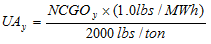
Where:
Ozone Season unit.
converted gross electrical output, as applicable, for a new CAIR NO x Ozone Season unit.
5) The Agency will allocate CAIR NO x Ozone Season allowances from the NUSA to new CAIR NO x Ozone Season units as follows:
A) If the NUSA for the control period for which CAIR NO x Ozone Season allowances are requested has a number of allowances greater than or equal to the total unprorated allocations for all new units requesting allowances, the Agency will allocate the number of allowances using the unprorated allocation determined for that unit pursuant to subsection (d)(4) of this Section, to the extent that whole allowances may be allocated. For any additional allowances beyond this allocation of whole allowances, the Agency will retain the additional allowances in the NUSA for allocation pursuant to this Section in later control periods.
B) If the NUSA for the control period for which the allowances are requested has a number of CAIR NO x Ozone Season allowances less than the total unprorated allocation to all new CAIR NO x Ozone Season units requesting allocations, the Agency will allocate the available allowances for new CAIR NO x Ozone Season units on a pro-rata basis, using the unprorated allocation determined for that unit pursuant to subsection (d)(4) of this Section, to the extent that whole allowances may be allocated. For any additional allowances beyond this allocation of whole allowances, the Agency will retain the additional allowances in the NUSA for allocation pursuant to this Section in later control periods.
e) The Agency will review each NUSA allowance allocation request pursuant to subsection (b) of this Section. The Agency will accept a NUSA allowance allocation request only if the request meets, or is adjusted by the Agency as necessary to meet, the requirements of this Section.
f) By June 1 of the applicable control period, the Agency will notify each CAIR designated representative that submitted a NUSA allowance request of the amount of CAIR NO x Ozone Season allowances from the NUSA, if any, allocated for the control period to the new unit covered by the request.
g) The Agency will allocate CAIR NO x Ozone Season allowances to new units from the NUSA no later than July 31 of the applicable control period.
h) After a new CAIR NO x Ozone Season unit has operated in one control period, it becomes an existing unit for the purposes of calculating future allocations in Section 225.540 only, and the Agency will allocate CAIR NO x Ozone Season allowances for that unit, for the control period commencing five control periods after the control period in which the unit commenced commercial operation, pursuant to Section 225.540. The new CAIR NO x Ozone Season unit will continue to receive CAIR NO x Ozone Season allowances from the NUSA according to this Section until the unit is eligible to use the CAIR NO x Ozone Season allowances allocated to the unit pursuant to Section 225.540.
i) If, after the completion of the procedures in subsection (c) of this Section for a control period, any unallocated CAIR NO x Ozone Season allowances remain in the NUSA for the control period, the Agency will, at a minimum, accrue those CAIR NO x Ozone Season allowances for future control period allocations to new CAIR NO x Ozone Season units. The Agency may from time to time elect to retire CAIR NO x Ozone Season allowances in the NUSA that are in excess of 7,245 for the purposes of continued progress toward attainment and maintenance of National Ambient Air Quality Standards pursuant to the CAA.
(Source: Added at 31 Ill. Reg. 12864, effective August 31, 2007)
Section 225.550 Monitoring, Recordkeeping and Reporting Requirements for Gross Electrical Output and Useful Thermal Energy
a) By January 1, 2008, or by the date of commencing commercial operation, whichever is later, the owner or operator of the CAIR NO x Ozone Season unit must operate a system for accurately measuring gross electrical output that is consistent with the requirements of either 40 CFR 60 or 75; must measure gross electrical output in MWh using such a system; and must record the output of the measurement system at all times. If a generator is served by two or more units, the information to determine each unit’s heat input for that control period must also be recorded, so as to allow each unit’s share of the gross electrical output to be determined. If heat input data is used, the owner or operator must comply with the applicable provisions of 40 CFR 75, as incorporated by reference in Section 225.140.
b) For a CAIR NO x Ozone Season unit that is a cogeneration unit by January 1, 2008, or by the date the CAIR NO x Ozone Season unit commences to produce useful thermal energy, whichever is later, the owner or operator of the unit with cogeneration capabilities must install, calibrate, maintain, and operate meters for steam flow in lbs/hr, temperature in degrees Fahrenheit, and pressure in PSI, to measure and record the useful thermal energy that is produced, in mmBtu/hr, on a continuous basis. Owners and operators of aCAIR NO x Ozone Season unit that produces useful thermal energy but uses an energy transfer medium other than steam, e.g., hot water or glycol, must install, calibrate, maintain, and operate the necessary meters to measure and record the necessary data to express the useful thermal energy produced, in mmBtu/hr, on a continuous basis. If the CAIR NO x Ozone Season unit ceases to produce useful thermal energy, the owner or operator may cease operation of these meters, provided that operation of such meters must be resumed if the CAIR NO x Ozone Season unit resumes production of useful thermal energy.
c) The owner or operator of a CAIR NO x Ozone Season unit must either report gross electrical output data to the Agency or comply with the applicable provisions for providing heat input data to USEPA as follows:
1) By September 15, 2007, the gross electrical output for control periods 2001, 2002, 2003, 2004 and 2005, if available, and the unit’s useful thermal energy data, if applicable. If a generator is served by two or more units, the documentation needed to determine each unit’s share of the heat input of such units for that control period must also be submitted. If heat input data is used, the owner or operator must comply with the applicable provisions of 40 CFR 75, as incorporated by reference in Section 225.140.
2) By June 1, 2008, the gross electrical output for control periods 2006 and 2007, if available, and the unit’s useful thermal energy data, if applicable. If a generator is served by two or more units, the documentation needed to determine each unit’s share of the heat input of such units for that control period must also be submitted. If heat input data is used, the owner or operator must comply with the applicable provisions of 40 CFR 75, as incorporated by reference in Section 225.140.
d) Beginning with 2008, the CAIR designated representative of the CAIR NO x Ozone Season unit must submit to the Agency quarterly, by no later than April 30, July 31, October 31, and January 31 of each year, information for the CAIR NO x Ozone Season unit’s gross electrical output, on a monthly basis for the prior quarter, and, if applicable, the unit’s useful thermal energy for each month.
e) The owner or operator of a CAIR NO x Ozone Season unit must maintain on-site the monitoring plan detailing the monitoring system, maintenance of the monitoring system, including quality assurance activities pursuant to the requirements of 40 CFR 60 or 75, as applicable, including the appropriate provisions for the measurement of gross electrical output for the CAIR NO x Ozone Season Trading Program and, if applicable, for new units. The monitoring plan must include, but is not limited to:
1) A description of the system to be used for the measurement of gross electrical output pursuant to Section 225.550(a), including a list of any data logging devices, solid-state kW meters, rotating kW meters, electromechanical kW meters, current transformers, transducers, potential transformers, pressure taps, flow venturi, orifice plates, flow nozzles, vortex meters, turbine meters, pressure transmitters, differential pressure transmitters, temperature transmitters, thermocouples, resistance temperature detectors, and any equipment or methods used to accurately measure gross electrical output.
2) A certification statement by the CAIR designated representative that all components of the gross electrical output system have been tested to be accurate within three percent and that the gross electrical output system is accurate to within ten percent.
f) The owner or operator of a CAIR NO x Ozone Season unit must retain records for at least five years from the date the record is created or the data is collected under subsections (a) and (b) of this Section, and the reports are submitted to the Agency and USEPA in accordance with subsections (c) and (d) of this Section. The owner or operator of a CAIR NO x Ozone Season unit must retain the monitoring plan required in subsection (e) of this Section for at least five years from the date that it is replaced by a new or revised monitoring plan.
(Source: Added at 31 Ill. Reg. 12864, effective August 31, 2007)
Section 225.555 Clean Air Set-Aside (CASA)
a) A project sponsor may apply for allowances from the CASA for sponsoring an energy efficiency and conservation, renewable energy, or clean technology project as set forth in Section 225.560 by submitting the application required by Section 225.570.
b) Notwithstanding subsection (a) of this Section, a project sponsor with a CAIR NO x Ozone Season source that is out of compliance with this Subpart for a given control period may not apply for allowances from the CASA for that control period. If a source receives CAIR NO x Ozone Season allowances from the CASA and then is subsequently found to have been out of compliance with this Subpart for the applicable control period or periods, the project sponsor must restore the CAIR NO x Ozone Season allowances that it received pursuant to its CASA request or an equivalent number of CAIR NO x Ozone Season allowances to the CASA within six months after receipt of an Agency notice that NO x Ozone Season allowances must be restored. These allowances will be assigned to the fund from which they were distributed.
c) CAIR NO x Ozone Season allowances from the CASA will be allocated in accordance with the procedures in Section 225.575.
d) The project sponsor may submit an application that aggregates two or more projects under a CASA project category that would individually result in less than one allowance, but that equal at a minimum one whole allowance when aggregated.
(Source: Added at 31 Ill. Reg. 12864, effective August 31, 2007)
Section 225.560 Energy Efficiency and Conservation, Renewable Energy, and Clean
Technology Projects
a) Energy efficiency and conservation projects means any of the following projects implemented and located in Illinois:
1) Demand side management projects that reduce the overall power demand by using less energy include:
A) Smart building management software that more efficiently regulates power flows.
B) The use of or replacement to high efficiency motors, pumps, compressors, or steam systems.
C) Lighting retrofits.
2) Energy efficient new building construction projects include:
A) ENERGY STAR-qualified new home projects.
B) Measures to reduce or conserve energy consumption beyond the requirements of the Illinois Energy Conservation Code for Commercial Buildings [20 ILCS 687/6-3].
C) New residential construction projects that qualify for Energy Efficient Tax Incentives pursuant to the Energy Policy Act of 2005 (42 USC 15801 (2005)).
3) Supply-side energy efficiency projects include projects implemented to improve the efficiency in electricity generation by coal-fired power plants and the efficiency of electrical transmission and distribution systems.
4) Highly efficient power generation projects, such as, but not limited to, combined cycle projects, combined heat and power, and microturbines. To be considered a highly efficient power generation project pursuant to this subsection (a)(4), a project must meet the following applicable thresholds and criteria:
A) For combined heat and power projects generating both electricity and useful thermal energy for space, water, or industrial process heat, a rated-energy efficiency of at least 60 percent: the project shall not be a CAIR NO x Ozone Season unit.
B) For combined cycle projects rated at greater than 0.50 MW, a rated-energy efficiency of at least 50 percent.
C) For microturbine projects rated at or below 0.50 MW and all other projects a rated-energy efficiency of at least 40 percent.
b) Renewable energy project means any of the following projects implemented and located in Illinois:
1) Zero-emission electric generating projects, including wind, solar (thermal or photovoltaic), and hydropower projects. Eligible hydropower plants are restricted to new generators that are not replacements of existing generators, that commenced operation on or after January 1, 2006, and that do not involve the significant expansion of an existing dam or the construction of a new dam.
2) Renewable energy units are those units that generate electricity using more than 50 percent of the heat input, on an annual basis, from dedicated crops grown for energy production or the capture systems for methane gas from landfills, water treatment plants or sewage treatment plants, and organic waste biomass, and other similar sources of non-fossil fuel energy. Renewable energy projects do not include energy from incineration by burning or heating of waste wood, tires, garbage, general household waste, institutional lunchroom waste, office waste, landscape waste, or construction or demolition debris.
c) Clean technology projects for reducing emissions from producing electricity and useful thermal energy means any of the following projects implemented and located in Illinois:
1) Air pollution control equipment upgrades for control of NO x emissions at existing coal-fired EGUs, as follows: installation of a selective catalytic reduction (SCR) or selective non-catalytic reduction (SNCR) system, or other emission control technologies. For this purpose, a unit will be considered “existing” after it has been in commercial operation for at least eight years. Air pollution control upgrades do not include the addition of low NO x burners, overfired air techniques, gas reburning techniques, flue gas conditioning techniques for the control of NO x emissions, projects involving upgrades or replacement of electrostatic precipitators, or addition of an activated carbon injection, or other sorbent injection for control of mercury.
2) Clean coal technologies projects include:
A) Integrated gasification combined cycle (IGCC) plants.
B) Fluidized bed coal combustion that commenced operation prior to December 31, 2006.
d) In addition to those projects excluded in subsections (a) through (c) of this Section, the following projects are also not energy efficiency and conservation, renewable energy, or clean technology projects:
1) Nuclear power projects.
2) Projects required to meet emission standards or technology requirements under State or federal law or regulation, except that allowances may be allocated for projects undertaken pursuant to Section 225.233 or Subpart F.
3) Projects used to meet the requirements of a court order or consent decree, except that allowances may be allocated for:
A) Emission rates or limits achieved that are lower than what is required to meet the emission rates or limits for SO 2 or NO x, or for installing a baghouse as provided for in a court order or consent decree entered into before May 30, 2006.
B) Projects used to meet the requirements of a court order or consent decree entered into on or after May 30, 2006, if the court order or consent decree does not specifically preclude such allocations.
4) A Supplemental Environmental Project (SEP).
e) Applications for projects implemented and located in Illinois that are not specifically listed in subsections (a) through (c) of this Section, and that are not specifically excluded by definition in subsections (a) through (c) of this Section or by specific exclusion in subsection (d) of this Section, may be submitted to the Agency. The application must designate which category or categories from those listed in subsections (a)(1) through (c)(2)(B) of this Section best fit the proposed project and the applicable formula pursuant to Section 225.565(b) to calculate the number of allowances that it is requesting. The Agency will determine whether the application is approvable based on a sufficient demonstration by the project sponsor that the project is a new type of energy efficiency, renewable energy, or clean technology project, similar in its effects as the projects specifically listed in subsections (a) through (c) of this Section.
f) Early adopter projects include projects that meet the criteria for any energy efficiency and conservation, renewable energy, or clean technology projects listed in subsections (a), (b), (c), and (e) of this Section and commence construction between July 1, 2006 and December 31, 2012.
(Source: Added at 31 Ill. Reg. 12864, effective August 31, 2007)
Section 225.565 Clean Air Set-Aside (CASA) Allowances
a) The CAIR NO x Ozone Season allowances for the CASA for each control period will be assigned to the following categories of projects:
Phase I Phase II
(2009-2014) (2015 and thereafter)
1) Energy Efficiency and Conservation/ 3684 3479
Renewable Energy
2) Air Pollution Control Equipment 1535 1448
Upgrades
3) Clean Coal Technology Projects 1842 1738
4) Early Adopters 614 580
b) The following formulas must be used to determine the number of CASA allowances that may be allocated to a project per control period:
1) For an energy efficiency and conservation project pursuant to Section 225.560(a)(1) through (a)(4)(A), the number of allowances must be calculated using the number of megawatt hours of electricity that was not consumed during a control period and the following formula:
A = (MWh c ) ´ (1.5 lb/MWh) / 2000 lb
Where:
A = The number of allowances for a particular project.
MWh c = The number of megawatt hours of electricity
conserved or generated during a control period by a
project.
2) For a zero emission electric generating project pursuant to Section 225.560(b)(1), the number of allowances must be calculated using the number of megawatt hours of electricity generated during a control period and the following formula:
A = (MWh g ) ´ (2.0 lb/MWh) / 2000 lb
Where:
A = The number of allowances for a particular project
MWh g = The number of megawatt hours of electricity
generated during a control period by a project.
3) For a renewable energy emission unit pursuant to Section 225.560(b)(2), the number of allowances must be calculated using the number of megawatt hours of electricity generated during a control period and the following formula:
A = (MWh g ) ´ (0.5 lb/MWh) / 2000 lb
Where:
A = The number of allowances for a particular project.
MWh g = The number of MW hours of electricity generated
during a control period by a project.
4) For an air pollution control equipment upgrade project pursuant to Section 225.560(c)(1), the number of allowances must be calculated using the emission rate before and after replacement or improvement, and the following formula:
A = (MWh g ) ´ 0.10 ´ (ER B lb/MWh - ER A lb/MWh) / 2000 lb
Where:
A = The number of allowances for a particular project.
MWh g = The number of MWhs of electricity
generated during a control period by a project.
ER B = Average NO x emission rate based on CEMS data
from the most recent two control periods prior to
the replacement or improvement of the control equipment in lb/MWh, unless subject to a consent decree or court order. For units subject to a consent decree or court order entered into before May 30, 2006, ER B is limited to emission rates or limits that are lower than the emission rate or limit required in the consent decree or court order. On or after May 30, 2006, ER B is limited to emission rates or limits specified in the consent decree or court order. If such limit is not expressed in lb/MWh, the limit shall be converted into lb/MWh using a heat rate of 10 mmBtu/1 MW.
ER A = Average NO x emission rate for the applicable
control period data based on CEMS data in
lb/MWh.
5) For highly efficient power generation and clean coal technology projects:
A) For projects other than fluidized coal combustion pursuant to Section 225.560(a)(4)(B), (a)(4)(C), and (c)(2), the number of allowances must be calculated using the number of MWh of electricity the project generates during a control period and the following formula:
A = (MWh g ) ´ (1.0 lb/MWh – ER lb/MWh) / 2000 lb
Where:
A = The number of allowances for a particular
project.
MWh g = The number of megawatt hours of electricity
generated during a control period by a
project.
ER = Annual average NO x emission rate based on
CEMS data in 1b/MWh.
B) For fluidized bed coal combustion projects pursuant to Section 225.560(c)(2), the number of allowances shall be calculated using the number of gross MWh of electricity the project generates during a control period and the following formula:
A = (MWh g ) x (1.4 lb/MWh – ER lb/MWh) / 2000 lb
Where:
A = The number of allowances for a particular project.
MWh g = The number of gross MWh of electricity generated during a control period by a project.
ER = Annual NO x emission rate for the control
period based on CEMS data in lb/MWh.
6) For a CASA project that commences construction before December 31, 2012, in addition to the allowances allocated pursuant to subsections (b)(1) through (b)(5) of this Section, a project sponsor may also request additional allowances under the early adopter project category pursuant to Section 225.560(e) based on the following formula:
A = 1.0 + 0.10 ´ Σ A i
Where:
A = The number of allowances for a particular project as
determined in subsections (b)(1) through (b)(5) of
this Section.
A i = The number of allowances as determined in
subsection (b)(1), (b)(2), (b)(3), (b)(4) or (b)(5) of
this Section for a given project.
(Source: Added at 31 Ill. Reg. 12864, effective August 31, 2007)
Section 225.570 Clean Air Set-Aside (CASA) Applications
a) A project sponsor may request allowances if the project commenced construction on or after the dates listed in this subsection. The project sponsor may request and be allocated allowances from more than one CASA category for a project, if applicable.
1) Demand side management, energy efficient new construction, and supply side energy efficiency and conservation projects that commenced construction on or after January 1, 2003;
2) Fluidized bed coal combustion projects, highly efficient power generation operations projects, or renewable energy emission units, that commenced construction on or after January 1, 2001; and
3) All other projects on or after July 1, 2006.
b) Beginning with the 2009 control period and each control period thereafter, a project sponsor may request allowances from the CASA. The application must be submitted to the Agency by May 1 of the control period for which the allowances are being requested.
c) The allocation will be based on the electricity conserved or generated in the control period preceding the calendar year in which the application is submitted. To apply for a CAIR NO x Ozone Season allocation from the CASA, project sponsors must provide the Agency with the following information:
1) Identification of the project sponsor, including name, address, type of organization, certification that the project sponsor has met the definition of “project sponsor” as set forth in Section 225.130, and names of the principals or corporate officials.
2) The number of the CAIR NO x Ozone Season general or compliance account for the project and the name of the associated CAIR account representative.
3) A description of the project or projects, location, the role of the project sponsor in the projects, and a general explanation of how the amount of energy conserved or generated was measured, verified, and calculated, and the number of allowances requested with the supporting calculations. The number of allowances requested will be calculated using the applicable formula from Section 225.570(b).
4) Detailed information to support the request for allowances, including the following types of documentation for the measurement and verification of the NO x emissions reductions, electricity generated, or electricity conserved using established measurement verification procedures, as applicable. The measurement and verification required will depend on the type of project proposed.
A) As applicable, documentation of the project’s base and control period conditions and resultant base and control period energy data, using the procedures and methods included in M&V Guidelines: Measurement and Verification for Federal Energy Projects, incorporated by reference in Section 225.140, or other method approved by the Agency. Examples include:
i) Energy consumption and demand profiles;
ii) Occupancy type;
iii) Density and periods;
iv) Space conditions or plant throughput for each operating period and season. (for example, in a building this would include the light level and color, space temperature, humidity and ventilation);
v) Equipment inventory, nameplate data, location, and condition; and
vi) Equipment operating practices (schedules and set points, actual temperatures/pressures);
B) Emissions data, including, if applicable, CEMS data;
C) Information for rated–energy efficiency, including supporting documentation and calculations; and
D) Electricity, in MWh, generated or conserved for the applicable control period.
5) Notwithstanding the requirements of subsection (c)(4) of this Section, applications for fewer than five allowances may propose other reliable and applicable methods of quantification acceptable to the Agency.
6) Any additional information requested by the Agency to determine the correctness of the requested number of allowances, including site information, project specifications, supporting calculations, operating procedures, and maintenance procedures.
7) The following certification by the responsible official for the project sponsor and the applicable CAIR account representative for the project:
“I am authorized to make this submission on behalf of the project sponsor and the holder of the CAIR NO x Ozone Season general account or compliance account for which the submission is made. I certify under penalty of law that I have personally examined, and am familiar with, the statements and information submitted in this application and all its attachments. Based on my inquiry of those individuals with primary responsibility for obtaining the information, I certify that the statements and information are to the best of my knowledge and belief true, accurate, and complete. I am aware that there are significant penalties for submitting false statements and information or omitting required statements and information.”
d) A project sponsor may request allowances from the CASA for each project for a total number of control periods not to exceed the number of control periods listed in this subsection. After a project has been allocated allowances from the CASA, subsequent requests for the project from the project sponsor must include the information required by subsections (c)(1), (c)(2), (c)(3) and (c)(7) of this Section, a description of any changes or further improvements made to the project, and information specified in subsections (c)(5) and (c)(6) as specifically requested by the Agency.
1) For energy efficiency and conservation projects (except for efficient operation and renewable energy projects), for a total of eight control periods.
2) For early adopter projects, for a total of ten control periods.
3) For air pollution control equipment upgrades, for a total of 15 control periods.
4) For renewable energy projects, clean coal technology, and highly efficient power generation projects, for each year that the project is in operation.
e) A project sponsor must keep copies of all CASA applications and the documentation used to support the application for at least five years.
(Source: Added at 31 Ill. Reg. 12864, effective August 31, 2007)
Section 225.575 Agency Action on Clean Air Set-Aside (CASA) Applications
a) By September 1, 2009 and each September 1 thereafter, the Agency will determine the total number of allowances that are approvable for allocation to project sponsors based upon the applications submitted pursuant to Section 225.570.
1) The Agency will determine the number of CAIR NO x Ozone Season allowances that are approvable based on the formulas and the criteria for such projects. The Agency will notify a project sponsor within 90 days after receipt of an application if the project is not approvable, the number of allowances requested is not approvable, or additional information is needed by the Agency to complete its review of the application.
2) If the total number of CAIR NO x Ozone Season allowances requested for approved projects is less than or equal to the number of CAIR NO x Ozone Season allowances in the CASA project category, the number of allowances that are approved shall be allocated to each CAIR NO x Ozone Season compliance or general account.
3) If more CAIR NO x Ozone Season allowances are requested than the number of CAIR NO x Ozone Season allowances in a given CASA project category, allowances will be allocated on a pro-rata basis based on the number of allowances available, subject to further adjustment as provided for by subsection (b) of this Section. CAIR NO x Ozone Season allowances will be allocated, transferred, or used as whole allowances. The number of whole allowances will be determined by rounding down for decimals less than 0.5 and rounding up for decimals of 0.5 or greater.
b) For control periods 2011 and thereafter:
1) If there are, after the completion of the procedures in subsection (a) of this Section for a control period, any CAIR NO x Ozone Season allowances not allocated to a CASA project for the control period, the remaining allowances will accrue in each CASA project category up to twice the number of allowances that are assigned to the project category for each control period as set forth in Section 225.565 .
2) If any allowances remain after allocations pursuant to subsection (a) of this Section, the Agency will allocate these allowances pro-rata to projects that received fewer allowances than requested, based on the number of allowances not allocated but approved by the Agency for the project under CASA. No project may be allocated more allowances than approved by the Agency for the applicable control period.
3) If any allowances remain after the allocation of allowances pursuant to subsection (b)(2) of this Section, the Agency will then distribute pro-rata the remaining allowances to project categories that have fewer than twice the number of allowances assigned to the project category. The pro-rata distribution will be based on the difference between two times the project category and the number of allowances that remain in the project category.
4) If allowances still remain undistributed after the allocations and distributions in the subsections (b)(1) through (b)(3) are completed, the Agency may elect to retire any CAIR NO x Ozone Season allowances that have not been distributed to any CASA category, to continue progress toward attainment or maintenance of the National Ambient Air Quality Standards pursuant to the CAA.
(Source: Added at 31 Ill. Reg. 12864, effective August 31, 2007)
SUBPART F: COMBINED POLLUTANT STANDARDS
Section 225.600 Purpose (Repealed)
(Source: Repealed at 33 Ill. Reg. 10427, effective June 26, 2009)
Section 225.605 Applicability (Repealed)
(Source: Repealed at 33 Ill. Reg. 10427, effective June 26, 2009)
Section 225.610 Notice of Intent (Repealed)
(Source: Repealed at 33 Ill. Reg. 10427, effective June 26, 2009)
Section 225.615 Control Technology Requirements and Emissions Standards for Mercury (Repealed)
(Source: Repealed at 33 Ill. Reg. 10427, effective June 26, 2009)
Section 225.620 Emissions Standards for NO x and SO 2 (Repealed)
(Source: Repealed at 33 Ill. Reg. 10427, effective June 26, 2009)
Section 225.625 Control Technology Requirements for NO x , SO 2 , and PM Emissions (Repealed)
(Source: Repealed at 33 Ill. Reg. 10427, effective June 26, 2009)
Section 225.630 Permanent Shut Downs (Repealed)
(Source: Repealed at 33 Ill. Reg. 10427, effective June 26, 2009)
Section 225.635 Requirements for CAIR SO 2 , CAIR NO x , and CAIR NO x Ozone Season Allowances (Repealed)
(Source: Repealed at 33 Ill. Reg. 10427, effective June 26, 2009)
Section 225.640 Clean Air Act Requirements (Repealed)
(Source: Repealed at 33 Ill. Reg. 10427, effective June 26, 2009)
225.APPENDIX A Specified EGUs for Purposes of the CPS (Midwest Generation’s Coal-Fired Boilers as of July 1, 2006)
Plant
|
Permit
Number |
Boiler
|
Permit designation | CPS
Designation |
Crawford
|
031600AIN
|
7
|
Unit 7 Boiler BLR1 | Crawford 7
|
8
|
Unit 8 Boiler BLR2 | Crawford 8
|
||
Fisk
|
031600AMI
|
19
|
Unit 19 Boiler BLR19 | Fisk 19
|
Joliet
|
197809AAO
|
71
|
Unit 7 Boiler BLR71 | Joliet 7
|
72
|
Unit 7 Boiler BLR72 | Joliet 7
|
||
81
|
Unit 8 Boiler BLR81 | Joliet 8
|
||
82
|
Unit 8 Boiler BLR82 | Joliet 8
|
||
5
|
Unit 6 Boiler BLR5 | Joliet 6
|
||
Powerton
|
179801AAA
|
51
|
Unit 5 Boiler BLR51 | Powerton 5
|
52
|
Unit 5 Boiler BLR52 | Powerton 5
|
||
61
|
Unit 6 Boiler BLR61 | Powerton 6
|
||
62
|
Unit 6 Boiler BLR62 | Powerton 6
|
||
Waukegan
|
097190AAC
|
17
|
Unit 6 Boiler BLR17 | Waukegan 6
|
7
|
Unit 7 Boiler BLR7 | Waukegan 7
|
||
8
|
Unit 8 Boiler BLR8 | Waukegan 8
|
||
Will County
|
197810AAK
|
1
|
Unit 1 Boiler BLR1 | Will County 1
|
2
|
Unit 2 Boiler BLR2 | Will County 2
|
||
3
|
Unit 3 Boiler BLR3 | Will County 3
|
||
4
|
Unit 4 Boiler BLR4 | Will County 4
|
||
(Source: Amended at 39 Ill. Reg. 16225, effective December 7, 2015)
225.APPENDIX B Continuous Emission Monitoring Systems for Mercury
Section 1.1 Applicability
The provisions of this Appendix apply to sources subject to 35 Ill Admin. Code Part 225 mercury (Hg) mass emission reduction program.
Section 1.2 General Operating Requirements
a) Primary Equipment Performance Requirements. The owner or operator must ensure that each continuous mercury emission monitoring system and each auxiliary monitoring system required by this Appendix meets the equipment, installation and performance specifications in Exhibit A to this Appendix and is maintained according to the quality assurance and quality control procedures in Exhibit B to this Appendix.
b) Heat Input Rate Measurement Requirement. The owner or operator must determine and record the heat input rate, in units of mmBtu/hr, to each affected unit for every hour or part of an hour any fuel is combusted following the procedures in Exhibit C to this Appendix.
c) Primary Equipment Hourly Operating Requirements. The owner or operator must ensure that all continuous mercury emission monitoring systems and all auxiliary monitoring systems required by this Appendix are in operation and monitoring unit emissions at all times that the affected unit combusts any fuel except during periods of calibration, quality assurance, or preventive maintenance, performed pursuant to Section 1.5 of this Appendix and Exhibit B to this Appendix, periods of repair, periods of backups of data from the data acquisition and handling system, or recertification performed pursuant to Section 1.4 of this Appendix.
1) The owner or operator must ensure that each continuous emission monitoring system is capable of completing a minimum of one cycle of operation (sampling, analyzing and data recording) for each successive 15-minute interval. The owner or operator must reduce all volumetric flow, CO 2 concentration, O 2 concentration and mercury concentration data collected by the monitors to hourly averages. Hourly averages must be computed using at least one data point in each 15-minute quadrant of an hour, where the unit combusted fuel during that quadrant of an hour. Notwithstanding this requirement, an hourly average may be computed from at least two data points separated by a minimum of 15 minutes (where the unit operates for more than one quadrant of an hour) if data are unavailable as a result of the performance of calibration, quality assurance, or preventive maintenance activities pursuant to Section 1.5 of this Appendix and Exhibit B to this Appendix, or backups of data from the data acquisition and handling system, or recertification, pursuant to Section 1.4 of this Appendix. The owner or operator must use all valid measurements or data points collected during an hour to calculate the hourly averages. All data points collected during an hour must be, to the extent practicable, evenly spaced over the hour.
2) Failure of a CO 2 or O 2 emissions concentration monitor, mercury concentration monitor, flow monitor, or a moisture monitor to acquire the minimum number of data points for calculation of an hourly average in subsection (c)(1) of this Section must result in the failure to obtain a valid hour of data and the loss of such component data for the entire hour. For a moisture monitoring system consisting of one or more oxygen analyzers capable of measuring O 2 on a wet-basis and a dry-basis, an hourly average percent moisture value is valid only if the minimum number of data points is acquired for both the wet-and dry-basis measurements.
d) Optional Backup Monitor Requirements. If the owner or operator chooses to use two or more continuous mercury emission monitoring systems, each of which is capable of monitoring the same stack or duct at a specific affected unit, or group of units using a common stack, then the owner or operator must designate one monitoring system as the primary monitoring system, and must record this information in the monitoring plan, as provided for in Section 1.10 of this Appendix. The owner or operator must designate the other monitoring systems as backup monitoring systems in the monitoring plan. The backup monitoring systems must be designated as redundant backup monitoring systems, non-redundant backup monitoring systems, or reference method backup systems, as described in Section 1.4(d) of this Appendix. When the certified primary monitoring system is operating and not out-of-control as defined in Section 1.7 of this Appendix, only data from the certified primary monitoring system must be reported as valid, quality-assured data. Thus, data from the backup monitoring system may be reported as valid, quality-assured data only when the backup is operating and not out-of-control as defined in Section 1.7 of this Appendix (or in the applicable reference method in appendix A of 40 CFR 60, incorporated by reference in Section 225.140) and when the certified primary monitoring system is not operating (or is operating but out-of-control). A particular monitor may be designated both as a certified primary monitor for one unit and as a certified redundant backup monitor for another unit.
e) Minimum Measurement Capability Requirement. The owner or operator must ensure that each continuous emission monitoring system is capable of accurately measuring, recording, and reporting data, and must not incur an exceedance of the full scale range, except as provided in Section 2.1.2.3 of Exhibit A to this Appendix.
f) Minimum Recording and Recordkeeping Requirements. The owner or operator must record and report the hourly, daily, quarterly, and annual information collected under the requirements as specified in subpart G of 40 CFR 75, incorporated by reference in Section 225.140, and Section 1.11 through 1.13 of this Appendix.
Section 1.3 Special Provisions for Measuring Mercury Mass Emissions Using the Excepted Sorbent Trap Monitoring Methodology
For an affected coal-fired unit under 35 Ill Adm. Code 225 if the owner or operator elects to use sorbent trap monitoring systems (as defined in Section 225.130) to quantify mass emissions, the guidelines in subsections (a) through (l) of this Section must be followed for this excepted monitoring methodology:
a) For each sorbent trap monitoring system (whether primary or redundant backup), the use of paired sorbent traps, as described in Exhibit D to this Appendix, is required;.
b) Each sorbent trap must have a main section, a backup section and a third section to allow spiking with a calibration gas of known mercury concentration, as described in Exhibit D to this Appendix;.
c) A certified flow monitoring system is required
d) Correction for stack gas moisture content is required, and in some cases, a certified O 2 or CO 2 monitoring system is required (see Section 1.15(a)(4));.
e) Each sorbent trap monitoring system must be installed and operated in accordance with Exhibit D to this Appendix. The automated data acquisition and handling system must ensure that the sampling rate is proportional to the stack gas volumetric flow rate.
f) At the beginning and end of each sample collection period, and at least once in each unit operating hour during the collection period, the gas flow meter reading must be recorded.
g) After each sample collection period, the mass of mercury adsorbed in each sorbent trap (in all three sections) must be determined according to the applicable procedures in Exhibit D to this Appendix.
h) The hourly mercury mass emissions for each collection period are determined using the results of the analyses in conjunction with contemporaneous hourly data recorded by a certified stack flow monitor, corrected for the stack gas moisture content. For each pair of sorbent traps analyzed, the average of the 2 mercury concentrations must be used for reporting purposes under Section 1.18(f) of this Appendix. Notwithstanding this requirement, if, due to circumstances beyond the control of the owner or operator, one of the paired traps is accidentally lost, damaged, or broken and cannot be analyzed, the results of the analysis of the other trap may be used for reporting purposes, provided that the other trap has met all of the applicable quality-assurance requirements of this Part.
i) All unit operating hours for which valid mercury concentration data are obtained with the primary sorbent trap monitoring system (as verified using the quality assurance procedures in Exhibit D to this Appendix) must be reported in the electronic quarterly report under Section 1.18(f) of this Appendix. For hours in which data from the primary monitoring system are invalid, the owner or operator may, in accordance with Section 1.4(d) of this Appendix, report valid mercury concentration data from: A certified redundant backup CEMS or sorbent trap monitoring system; a certified non-redundant backup CEMS or sorbent trap monitoring system; or an applicable reference method under Section 1.6 of this Appendix.
j) Initial certification requirements and additional quality-assurance requirements for the sorbent trap monitoring systems are found in Section 1.4(c)(7), in Section 6.5.6 of Exhibit A to this Appendix, in Sections 1. 3 and 2.3 of Exhibit B to this Appendix, and in Exhibit D to this Appendix.
k) During each RATA of a sorbent trap monitoring system, the type of sorbent material used by the traps must be the same as for daily operation of the monitoring system. A new pair of traps must be used for each RATA run. However, the size of the traps used for the RATA may be smaller than the traps used for daily operation of the system.
l) Whenever the type of sorbent material used by the traps is changed, the owner or operator must conduct a diagnostic RATA of the modified sorbent trap monitoring system within 720 unit or stack operating hours after the date and hour when the new sorbent material is first used. If the diagnostic RATA is passed, data from the modified system may be reported as quality-assured, back to the date and hour when the new sorbent material was first used. If the RATA is failed, all data from the modified system must be invalidated,back to the date and hour when the new sorbent material was first used, and data from the system must remain invalid until a subsequent RATA is passed. If the required RATA is not completed within 720 unit or stack operating hours, but is passed on the first attempt, data from the modified system must be invalidated beginning with the first operating hour after the 720 unit or stack operating hour window expires and data from the system must remain invalid until the date and hour of completion of the successful RATA.
Section 1.4 Initial Certification and Recertification Procedures
a) Initial Certification Approval Process. The owner or operator must ensure that each continuous mercury emission monitoring system or auxiliary monitoring system required by this Appendix meets the initial certification requirements of this Section. In addition, whenever the owner or operator installs a continuous mercury emission monitoring system in order to meet the requirements of Section 1.3 of this Appendix and 40 CFR sections 75.11 through 75.14 and 75.16 through 75.18 , incorporated by reference in Section 225.140, where no continuous emission monitoring system was previously installed, initial certification is required.
1) Notification of initial certification test dates. The owner or operator must submit a written notice of the dates of initial certification testing at the unit as specified in 40 CFR 75.61 (a)(1), incorporated by reference in Section 225.140.
2) Certification application. The owner or operator must apply for certification of each continuous mercury emission monitoring system and, if not previously certified, for each auxiliary monitoring system. The owner or operator must submit the certification application in accordance with 40 CFR 75.60 , incorporated by reference in Section 225.140, and each complete certification application must include the information specified in 40 CFR 75.63 , incorporated by reference in Section 225.140.
3) Provisional approval of certification (or recertification) applications. Upon the successful completion of the required certification (or recertification) procedures of this Section, each continuous mercury emission monitoring system and each auxiliary monitoring system must be deemed provisionally certified (or recertified) for use for a period not to exceed 120 days following receipt by the Agency of the complete certification (or recertification) application under subsection (a)(4) of this Section. Data measured and recorded by a provisionally certified (or recertified) continuous emission monitoring system, operated in accordance with the requirements of Exhibit B to this Appendix, will be considered valid quality-assured data (retroactive to the date and time of provisional certification or recertification), provided that the Agency does not invalidate the provisional certification (or recertification) by issuing a notice of disapproval within 120 days of receipt by the Agency of the complete certification (or recertification) application. Note that when the conditional data validation procedures of subsection (b)(3) of this Section are used for the initial certification (or recertification) of a continuous emissions monitoring system, the date and time of provisional certification (or recertification) of the CEMS may be earlier than the date and time of completion of the required certification (or recertification) tests.
4) Certification (or recertification) application formal approval process. The Agency will issue a notice of approval or disapproval of the certification (or recertification) application to the owner or operator within 120 days after receipt of the complete certification (or recertification) application. In the event the Agency does not issue such a notice within 120 days after receipt, each continuous emission monitoring system which meets the performance requirements of this Part and is included in the certification (or recertification) application will be deemed certified (or recertified) for use under 35 Ill Adm. Code 225.
A) Approval notice. If the certification (or recertification) application is complete and shows that each continuous emission monitoring system meets the performance requirements of this part, then the Agency will issue a notice of approval of the certification (or recertification) application within 120 days of receipt.
B) Incomplete application notice. A certification (or recertification) application will be considered complete when all of the applicable information required to be submitted in 40 CFR 75.63 , incorporated by reference in Section 225.140, has been received by the Agency. If the certification (or recertification) application is not complete, then the Agency will issue a notice of incompleteness that provides a reasonable timeframe for the owner or operator to submit the additional information required to complete the certification (or recertification) application. If the owner or operator has not complied with the notice of incompleteness by a specified due date, then the Agency may issue a notice of disapproval specified under paragraph (a)(4)(C) of this Section. The 120-day review period will not begin prior to receipt of a complete application.
C) Disapproval notice. If the certification (or recertification) application shows that any continuous emission monitoring system does not meet the performance requirements of this part, or if the certification (or recertification) application is incomplete and the requirement for disapproval under subsection (a)(4)(B) of this Section has been met, the Agency must issue a written notice of disapproval of the certification (or recertification) application within 120 days after receipt. By issuing the notice of disapproval, the provisional certification (or recertification) is invalidated by the Agency, and the data measured and recorded by each uncertified continuous emission or opacity monitoring system must not be considered valid quality-assured data as follows: from the hour of the probationary calibration error test that began the initial certification (or recertification) test period (if the conditional data validation procedures of subsection (b)(3) of this Section were used to retrospectively validate data); or from the date and time of completion of the invalid certification or recertification tests (if the conditional data validation procedures of subsection (b)(3) of this Section were not used). The owner or operator must follow the procedures for loss of initial certification in subsection (a)(5) of this Section for each continuous emission monitoring system that is disapproved for initial certification. For each disapproved recertification, the owner or operator must follow the procedures of subsection (b)(5) of this Section.
5) Procedures for loss of certification. When the Agency issues a notice of disapproval of a certification application or a notice of disapproval of certification status (as specified in subsection (a)(4) of this Section), then:
A) Until such time, date, and hour as the continuous mercury emission monitoring system can be adjusted, repaired, or replaced and certification tests successfully completed (or, if the conditional data validation procedures in subsections (b)(3)(B) through (I) of this Section are used, until a probationary calibration error test is passed following corrective actions in accordance with subsection (b)(3)(B) of this Section), the owner or operator must perform emissions testing pursuant to Section 225.239.;
B) The owner or operator must submit a notification of certification pretest dates as specified in Section 225.250(a)(3)(A) and a new certification application according to the procedures in Section 225.250(a)(3)(B); and
C) The owner or operator must repeat all certification tests or other requirements that were failed by the continuous mercury emission monitoring system, as indicated in the Agency’s notice of disapproval, no later than 30 unit operating days after the date of issuance of the notice of disapproval.
b) Recertification Approval Process. Whenever the owner or operator makes a replacement, modification, or change in a certified continuous mercury emission monitoring system or auxiliary monitoring system that may significantly affect the ability of the system to accurately measure or record the gas volumetric flow rate, mercury concentration, percent moisture, or to meet the requirements of Section 1.5 of this Appendix or Exhibit B to this Appendix, the owner or operator must recertify the monitoring system, according to the procedures in this subsection. Examples of changes that require recertification include: replacement of the analyzer; change in location or orientation of the sampling probe or site; and complete replacement of an existing monitoring system. The owner or operator must also recertify the continuous emission monitoring systems for a unit that has recommenced commercial operation following a period of long-term cold storage as defined in Section 225.130. Any change to a flow monitor or gas monitoring system for which a RATA is not necessary will not be considered a recertification event. In addition, changing the polynomial coefficients or K-factors of a flow monitor will require a 3-load RATA, but is not considered to be a recertification event; however, records of the polynomial coefficients or K-factors currently in use must be maintained on-site in a format suitable for inspection. Changing the coefficient or K-factors of a moisture monitoring system will require a RATA, but is not considered to be a recertification event; however, records of the coefficient or K-factors currently in use by the moisture monitoring system must be maintained on-site in a format suitable for inspection. In such cases, any other tests that are necessary to ensure continued proper operation of the monitoring system (e.g., 3-load flow RATAs following changes to flow monitor polynomial coefficients, linearity checks, calibration error tests, DAHS verifications, etc.) must be performed as diagnostic tests, rather than as recertification tests. The data validation procedures in subsection (b)(3) of this Section must be applied to RATAs associated with changes to flow or moisture monitor coefficients, and to linearity checks, 7-day calibration error tests, and cycle time tests, when these are required as diagnostic tests. When the data validation procedures of subsection (b)(3) of this Section are applied in this manner, replace the word "recertification" with the word "diagnostic."
1) Tests required. For all recertification testing, the owner or operator must complete all initial certification tests in subsection (c) of this Section that are applicable to the monitoring system, except as otherwise approved by the Agency. For diagnostic testing after changing the flow rate monitor polynomial coefficients, the owner or operator must complete a 3-level RATA. For diagnostic testing after changing the K factor or mathematical algorithm of a moisture monitoring system, the owner or operator must complete a RATA.
2) Notification of recertification test dates. The owner or operatorormust submit notice of testing dates for recertification under this subsection as specified in 40 CFR 75.61 (a)(1)(ii), incorporated by reference in Section 225.140, unless all of the tests in subsection (c) of this Section are required for recertification, in which case the owner or operator must provide notice in accordance with the notice provisions for initial certification testing in 40 CFR 75.61 (a)(1)(i), incorporated by reference in Section 225.140.
3) Recertification test period requirements and data validation. The data validation provisions in subsections (b)(3)(A) through (b)(3)(I) of this Section will apply to all mercury CEMS recertifications and diagnostic testing. The provisions in subsections (b)(3)(B) through (b)(3)(I) of this Section may also be applied to initial certifications (see Sections 6.2(a), 6.3.1(a), 6.3.2(a), 6.4(a) and 6.5(f) of Exhibit A to this Appendix) and may be used to supplement the linearity check and RATA data validation procedures in Sections 2.2.3(b) and 2.3.2(b) of Exhibit B to this Appendix.
A) The owner or operator must report emission data using a reference method or another monitoring system that has been certified or approved for use under this Part, in the period extending from the hour of the replacement, modification, or change made to a monitoring system that triggers the need to perform recertification testing, until either: the hour of successful completion of all of the required recertification tests; or the hour in which a probationary calibration error test (according to subsection (b)(3)(B) of this Section) is performed and passed, following all necessary repairs, adjustments, or reprogramming of the monitoring system. The first hour of quality-assured data for the recertified monitoring system must either be the hour after all recertification tests have been completed or, if conditional data validation is used, the first quality-assured hour must be determined in accordance with subsections (b)(3)(B) through (b)(3)(I) of this Section. Notwithstanding these requirements, if the replacement, modification, or change requiring recertification of the CEMS is such that the historical data stream is no longer representative (e.g., where the mercury concentration and stack flow rate change significantly after installation of a wet scrubber), the owner or operator must estimate the mercury emissions over that time period and notify the Agency within 15 days after the replacement, modification, or change requiring recertification of the CEMS.
B) Once the modification or change to the CEMS has been completed and all of the associated repairs, component replacements, adjustments, linearization and reprogramming of the CEMS have been completed, a probationary calibration error test is required to establish the beginning point of the recertification test period. In this instance, the first successful calibration error test of the monitoring system following completion of all necessary repairs, component replacements, adjustments, linearization and reprogramming must be the probationary calibration error test. The probationary calibration error test must be passed before any of the required recertification tests are commenced.
C) Beginning with the hour of commencement of a recertification test period, emission data recorded by the CEMS are considered to be conditionally valid, contingent upon the results of the subsequent recertification tests.
D) Each required recertification test must be completed no later than the following number of unit operating hours (or unit operating days) after the probationary calibration error test that initiates the test period:
i) For a linearity check, a system integrity check, and/or cycle time test, 168 consecutive unit operating hours, as defined in 40 CFR 72.2 , incorporated by reference in Section 225.140, or, for CEMS installed on common stacks or bypass stacks, 168 consecutive stack operating hours, as defined in 40 CFR 72.2 ;
ii) For a RATA (whether normal-load or multiple-load), 720 consecutive unit operating hours, as defined in 40 CFR 72.2 , incorporated by reference in Section 225.140, or, for CEMS installed on common stacks or bypass stacks, 720 consecutive stack operating hours, as defined in 40 CFR 72.2 ; and
iii) For a 7-day calibration error test, 21 consecutive unit operating days, as defined in 40 CFR 72.2 , incorporated by reference in Section 225.140.
E) All recertification tests must be performed hands-off. No adjustments to the calibration of the CEMS, other than the routine calibration adjustments following daily calibration error tests as described in Section 2.1.3 of Exhibit B to this Appendix, are permitted during the recertification test period. Routine daily calibration error tests must be performed throughout the recertification test period, in accordance with Section 2.1.1 of Exhibit B to this Appendix. The additional calibration error test requirements in Section 2.1.3 of Exhibit B to this Appendix, must also apply during the recertification test period.
F) If all of the required recertification tests and required daily calibration error tests are successfully completed in succession with no failures, and if each recertification test is completed within the time period specified in subsection (b)(3)(D)(i), (ii) or (iii) of this Section, then all of the conditionally valid emission data recorded by the CEMS will be considered quality assured, from the hour of commencement of the recertification test period until the hour of completion of the required tests.
G) If a required recertification test is failed or aborted due to a problem with the CEMS, or if a daily calibration error test is failed during a recertification test period, data validation must be done as follows:
i) If any required recertification test is failed, it must be repeated. If any recertification test other than a 7-day calibration error test is failed or aborted due to a problem with the mercury CEMS, the original recertification test period is ended, and a new recertification test period must be commenced with a probationary calibration error test. The tests that are required in the new recertification test period will include any tests that were required for the initial recertification event that were not successfully completed and any recertification or diagnostic tests that are required as a result of changes made to the monitoring system to correct the problems that caused the failure of the recertification test. For a 2- or 3-load flow RATA, if the relative accuracy test is passed at one or more load levels, but is failed at a subsequent load level, provided that the problem that caused the RATA failure is corrected without re-linearizing the instrument, the length of the new recertification test period must be equal to the number of unit operating hours remaining in the original recertification test period, as of the hour of failure of the RATA. However, if re-linearization of the flow monitor is required after a flow RATA is failed at a particular load level, then a subsequent 3-load RATA is required, and the new recertification test period must be 720 consecutive unit (or stack) operating hours. The new recertification test sequence must not be commenced until all nece ssary maintenance activities, adjustments, linearization and reprogramming of the CEMS have been completed;.
ii) If a linearity check, RATA system integrity check, or cycle time test is failed or aborted due to a problem with the mercury CEMS, all conditionally valid emission data recorded by the CEMS are invalidated, from the hour of commencement of the recertification test period to the hour in which the test is failed or aborted, except for the case in which a multiple-load flow RATA is passed at one or more load levels, failed at a subsequent load level, and the problem that caused the RATA failure is corrected without re-linearizing the instrument. In that case, data invalidation will be prospective, from the hour of failure of the RATA until the commencement of the new recertification test period. Data from the CEMS remain invalid until the hour in which a new recertification test period is commenced, following corrective action, and a probationary calibration error test is passed, at which time the conditionally valid status of emission data from the CEMS begins again;.
iii) If a 7-day calibration error test is failed within the recertification test period, previously-recorded conditionally valid emission data from the mercury CEMS are not invalidated. The conditionally valid data status is unaffected, unless the calibration error on the day of the failed 7-day calibration error test exceeds twice the performance specification in Section 3 of Exhibit A to this Appendix, as described in subsection (b)(3)(G)(iv) of this Section.
iv) If a daily calibration error test is failed during a recertification test period (i.e., the results of the test exceed the applicable performance specification in Section32.1.4 of ExhibitAB to this Appendix), the CEMS is out-of-control as of the hour in which the calibration error test is failed. Emission data from the CEMS will be invalidated prospectively from the hour of the failed calibration error test until the hour of completion of a subsequent successful calibration error test following corrective action, at which time the conditionally valid status of data from the monitoring system resumes. Failure to perform a required daily calibration error test during a recertification test period will also cause data from the CEMS to be invalidated prospectively, from the hour in which the calibration error test was due until the hour of completion of a subsequent successful calibration error test. Whenever a calibration error test is failed or missed during a recertification test period, no further recertification tests must be performed until the required subsequent calibration error test has been passed, re-establishing the conditionally valid status of data from the monitoring system. If a calibration error test failure occurs while a linearity check or RATA is still in progress, the linearity check or RATA must be re-started.
v) Trial gas injections and trial RATA runs are permissible during the recertification test period, prior to commencing a linearity check or RATA, for the purpose of optimizing the performance of the CEMS. The results of such gas injections and trial runs must not affect the status of previously-recorded conditionally valid data or result in termination of the recertification test period, provided that they meet the following specifications and conditions: for diluent gas injections, the stable, ending monitor response is within ±5 percent of the tag value of the reference gas or 0.5% CO 2 or O 2 . For Hg vapor injections, the stable, ending monitor response is within ± 10 percent of the value of the reference gas or 0.8 µg/scm; for RATA trial runs, the average reference method reading and the average CEMS reading for the run differ by no more than ± 10% of the average reference method value (for flow, diluent gas,and moisture monitors); or ± 20% of the average reference method value or 1.0µg/scm (for mercury monitors), or differ by no more than 1.0% CO 2 or O 2 or 1.5% H 2 O from the average reference method value, as applicable. No adjustments to the calibration of the CEMS shall be made following the trial injections or runs, other than the adjustments permitted under Section 2.1.3 of Exhibit B to this Appendix, if the CEMS is not repaired, re-linearized or reprogrammed (e.g., changing flow monitor polynomial coefficients, linearity constants, or K-factors) after the trial injections or runs.
vi) If the results of any trial gas injections or RATA runs are outside the limits in subsection (b)(3)(G)(v) of this Section or if the CEMS is repaired, re-linearized, or reprogrammed after the trial injections or runs the trial injections or runs will be counted as a failed linearity check or RATA attempt. If this occurs, follow the procedures pertaining to failed and aborted recertification tests in subsections (b)(3)(G)(i) and (b)(3)(G)(ii) of this Section.
H) If any required recertification test is not completed within its allotted time period, data validation must be done as follows.: for a late linearity test, RATA, system integrity check, or cycle time test that is passed on the first attempt, data from the monitoring system will be invalidated from the hour of expiration of the recertification test period until the hour of completion of the late test. For a late 7-day calibration error test, whether or not it is passed on the first attempt, data from the monitoring system will also be invalidated from the hour of expiration of the recertification test period until the hour of completion of the late test. For a late linearity test, RATA system integrity check, or cycle time test that is failed on the first attempt or aborted on the first attempt due to a problem with the monitor, all conditionally valid data from the monitoring system will be considered invalid back to the hour of the first probationary calibration error test that initiated the recertification test period. Data from the monitoring system will remain invalid until the hour of successful completion of the late recertification test and any additional recertification or diagnostic tests that are required as a result of changes made to the monitoring system to correct problems that caused failure of the late recertification test.
I) If any required recertification test of a monitoring system has not been completed by the end of a calendar quarter and if data contained in the quarterly report are conditionally valid pending the results of tests to be completed in a subsequent quarter, the owner or operator must indicate this by means of notification within the quarterly report for that quarter. The owner or operator must resubmit the report for that quarter if the required recertification test is subsequently failed. If any required recertification test is not completed by the end of a particular calendar quarter but is completed no later than 30 days after the end of that quarter (i.e., prior to the deadline for submitting the quarterly report under 40 CFR 75.64 , incorporated by reference in Section 225.140), the test data and results may be submitted with the earlier quarterly report even though the test dates are from the next calendar quarter. In such instances, if the recertification tests are passed in accordance with the provisions of subsection (b)(3) of this Section, conditionally valid data may be reported as quality-assured . The Agency may invalidate any conditionally valid data that remains unresolved at the end of a particular calendar year.
4) Recertification application. The owner or operator must apply for recertification of each continuous emission monitoring system. The owner or operator must submit the recertification application in accordance with 40 CFR 75.60, incorporated by reference in Section 225.140, and each complete recertification application must include the information specified in 40 CFR 75.63 , incorporated by reference in Section 225.140.
5) Approval or disapproval of request for recertification. The procedures for provisional certification in subsection (a)(3) of this Section apply to recertification applications. The Agency will issue a notice of approval, disapproval, or incompleteness according to the procedures in subsection (a)(4) of this Section. Data from the monitoring system remain invalid until all required recertification tests have been passed or until a subsequent probationary calibration error test is passed, beginning a new recertification test period. The owner or operator must repeat all recertification tests or other requirements, as indicated in the Agency’s notice of disapproval, no later than 30 unit operating days after the date of issuance of the notice of disapproval. The owner or operator must submit a notification of the recertification retest dates, as specified in 40 CFR 75.61 (a)(1)(ii), incorporated by reference in Section 225.140, and must submit a new recertification application according to the procedures in subsection (b)(4) of this Section.
c) Initial Certification and Recertification Procedures. Prior to the applicable deadline in 35 Ill Adm.. Code 225.240(b), the owner or operator must conduct initial certification tests and in accordance with 40 CFR 75.63 , incorporated by reference in Section 225.140, the owner or operator must submit an application to demonstrate that the continuous emission monitoring system and components of the system meet the specifications in Exhibit A to this Appendix. The owner or operator must compare reference method values with output from the automated data acquisition and handling system that is part of the continuous mercury emission monitoring system being tested. Except as otherwise specified in subsections (b)(1), (d), and (e) of this Section, and in Sections 6.3.1 and 6.3.2 of Exhibit A to this Appendix, the owner or operator must perform the following tests for initial certification or recertification of continuous emission monitoring systems according to the requirements of Exhibit B to this Appendix:
1) For each mercury concentration monitoring system:
A) A 7-day calibration error test;
B) A linearity check, for mercury monitors, perform this check with elemental mercury standards;
C) A relative accuracy test audit must be done on a µg/scm basis;
D) A cycle time test;
E) For mercury monitors a 3-level system integrity check, using a NIST-traceable source of oxidized mercury, as described in Section 6.2 of Exhibit A to Appendix. This test is not required for a mercury monitor that does not have a converter.
2) For each flow monitor:
A) A 7-day calibration error test;
B) Relative accuracy test audits, as follows:
i) A single-load RATA at the normal load, as defined in Section 6.5.2.1(d) of Exhibit A to this Appendix, for a flow monitor installed on a peaking unit or bypass stack, or for a flow monitor exempted from multiple-load RATA testing under Section 6.5.2(e) of Exhibit A to this Appendix;
ii) For all other flow monitors, a RATA at each of the three load levels (or operating levels) corresponding to the three flue gas velocities described in Section 6.5.2(a) of Exhibit A to this Appendix;.
3) For each diluent gas monitor used only to monitor heat input rate:
A) A 7-day calibration error test;
B) A linearity check;
C) A relative accuracy test audit, where, for an O 2 monitor used to determine CO 2 concentration, the CO 2 reference method must be used for the RATA; and
D) A cycle-time test.
4) For each continuous moisture monitoring system consisting of wet- and dry-basis O 2 analyzers:
A) A 7-day calibration error test of each O 2 analyzer;
B) A cycle time test of each O 2 analyzer;
C) A linearity test of each O 2 analyzer; and
D) A RATA directly comparing the percent moisture measured by the monitoring system to a reference method.
5) For each continuous moisture sensor: A RATA directly comparing the percent moisture measured by the monitor sensor to a reference method.
6) For a continuous moisture monitoring system consisting of a temperature sensor and a data acquisition and handling system (DAHS) software component programmed with a moisture lookup table: A demonstration that the correct moisture value for each hour is being taken from the moisture lookup tables and applied to the emission calculations. At a minimum, the demonstration must be made at three different temperatures covering the normal range of stack temperatures from low to high.
7) For each sorbent trap monitoring system, perform a RATA, on a µg/dscm basis.
8) For the automated data acquisition and handling system, tests designed to verify the proper computation of hourly averages for pollutant concentrations, flow rate, pollutant emission rates and pollutant mass emissions.
9) The owner or operator must provide adequate facilities for initial certification or recertification testing that include:
A) Sampling ports adequate for test methods applicable to such facility, such that;volumetric flow rate, pollutant concentration and pollutant emission rates can be accurately determined by applicable test methods and procedures; and
B) Basic facilities (e.g., electricity) for sampling and testing equipment.
d) Initial Certification and Recertification and Quality Assurance Procedures for Optional Backup Continuous Emission Monitoring Systems.
1) Redundant backups. The owner or operator of an optional redundant backup CEMS must comply with all the requirements for initial certification and recertification according to the procedures specified in subsections (a), (b) and (c) of this Section. The owner or operator must operate the redundant backup CEMS during all periods of unit operation, except for periods of calibration, quality assurance, maintenance or repair. The owner or operator must perform upon the redundant backup CEMS all quality assurance and quality control procedures specified in Exhibit B to this Appendix, except that the daily assessments in Section 2.1 of Exhibit B to this Appendix are optional for days on which the redundant backup CEMS is not used to report emission data under this Part. For any day on which a redundant backup CEMS is used to report emission data, the system must meet all of the applicable daily assessment criteria in Exhibit B to this Appendix.
2) Non-redundant backups. The owner or operator of an optional non-redundant backup CEMS or like-kind replacement analyzer must comply with all of the following requirements for initial certification, quality assurance, recertification and data reporting:
A) Except as provided in subsection (d)(2)(E) of this Section, for a regular non-redundant backup CEMS (i.e., a non-redundant backup CEMS that has its own separate probe, sample interface, and analyzer), or a non-redundant backup flow monitor, all of the tests in subsection (c) of this Section are required for initial certification of the system, except for the 7-day calibration error test.
B) For a like-kind replacement non-redundant backup analyzer (i.e., a non-redundant backup analyzer that uses the same probe and sample interface as a primary monitoring system), no initial certification of the analyzer is required.
C) Each non-redundant backup CEMS or like-kind replacement analyzer must comply with the daily and quarterly quality assurance and quality control requirements in Exhibit B to this Appendix for each day and quarter that the non-redundant backup CEMS or like-kind replacement analyzer is used to report data, and must meet the additional linearity and calibration error test requirements specified in this subsection. The owner or operator must ensure that each non-redundant backup CEMS or like-kind replacement analyzer passes a linearity check (for mercury concentration and diluent gas monitors) or a calibration error test (for flow monitors) prior to each use for recording and reporting emissions. When a non-redundant backup CEMS or like-kind replacement analyzer is brought into service, prior to conducting the linearity test, a probationary calibration error test (as described in subsection (b)(3)(B) of this Section), which will begin a period of conditionally valid data, may be performed in order to allow the validation of data retrospectively, as follows. Conditionally valid data from the CEMS or like-kind replacement analyzer are validated back to the hour of completion of the probationary calibration error test if the following conditions are met: if no adjustments are made to the CEMS or like-kind replacement analyzer other than the allowable calibration adjustments specified in Section 2.1.3 of Exhibit B to this Appendix between the probationary calibration error test and the successful completion of the linearity test; and if the linearity test is passed within 168 unit (or stack) operating hours of the probationary calibration error test. However, if the linearity test is performed within 168 unit or stack operating hours but is either failed or aborted due to a problem with the CEMS or like-kind replacement analyzer, then all of the conditionally valid data are invalidated back to the hour of the probationary calibration error test, and data from the non-redundant backup CEMS or from the primary monitoring system of which the like-kind replacement analyzer is a part remain invalid until the hour of completion of a successful linearity test. Notwithstanding this requirement, the conditionally valid data status may be re-established after a failed or aborted linearity check, if corrective action is taken and a calibration error test is subsequently passed. However, in no case will the use of conditional data validation extend for more than 168 unit or stack operating hours beyond the date and time of the original probationary calibration error test when the analyzer was brought into service.
D For each parameter monitored (i.e., CO 2 , O 2 , Hg or flow rate) at each unit or stack, a regular non-redundant backup CEMS may not be used to report data at that affected unit or common stack for more than 720 hours in any one calendar year (in accordance with 40 CFR 75.74(c) , incorporated by reference in Section 225.140), unless the CEMS passes a RATA at that unit or stack. For each parameter monitored at each unit or stack, the use of a like-kind replacement non-redundant backup analyzer (or analyzers) is restricted to 720 cumulative hours per calendar year, unless the owner or operator redesignates the like-kind replacement analyzers as components of regular non-redundant backup CEMS and each redesignated CEMS passes a RATA at that unit or stack.
E) For each regular non-redundant backup CEMS, no more than eight successive calendar quarters must elapse following the quarter in which the last RATA of the CEMS was done at a particular unit or stack, without performing a subsequent RATA. Otherwise, the CEMS may not be used to report data from that unit or stack until the hour of completion of a passing RATA at that location.
F) Each regular non-redundant backup CEMS must be represented in the monitoring plan required under Section 1.10 of this Appendix as a separate monitoring system, with unique system and component identification numbers. When like-kind replacement non-redundant backup analyzers are used, the owner or operator must represent each like-kind replacement analyzer used during a particular calendar quarter in the monitoring plan required under Section 1.10 of this Appendix as a component of a primary monitoring system. The owner or operator must also assign a unique component identification number to each like-kind replacement analyzer, beginning with the letters LK (e.g., LK1, LK2, etc.) and must specify the manufacturer, model and serial number of the like-kind replacement analyzer. This information may be added, deleted or updated as necessary, from quarter to quarter. The owner or operator must also report data from the like-kind replacement analyzer using the system identification number of the primary monitoring system and the assigned component identification number of the like-kind replacement analyzer.
G) When reporting data from a certified regular non-redundant backup CEMS, use a method of determination code “02”(MODC). When reporting data from a like-kind replacement non-redundant backup analyzer, use a MODC of "17" (see Table 4a under Section 1.11 of this Appendix).
H) For non-redundant backup mercury CEMS and sorbent trap monitoring systems, and for like-kind replacement mercury analyzers, the following provisions apply in addition to, or, in some cases, in lieu of, the general requirements in subsections (d)(2)(A) through (H) of this Section:
i) When a certified sorbent trap monitoring system is brought into service as a regular non-redundant backup monitoring system, the system must be operated according to the procedures in Section 1.3 of this Appendix and Exhibit D to this Appendix.
ii) When a regular non-redundant backup mercury CEMS or a like-kind replacement mercury analyzer is brought into service, a linearity check with elemental mercury standards, as described in subsection (c)(1)(B) of this Section and Section 6.2 of Exhibit A to this Appendix, and a single-point system integrity check, as described in Section 2.6 of Exhibit B to this Appendix, must be performed. Alternatively, a 3-level system integrity check, as described in subsection (c)(1)(E) of this Section and subsection (g) of Section 6.2 in Exhibit A to this Appendix, may be performed in lieu of these two tests.
iii) The weekly single-point system integrity checks described in Section 2.6 of Exhibit B to this Appendix are required as long as a non-redundant backup mercury CEMS or like-kind replacement mercury analyzer remains in service, unless the daily calibrations of the mercury analyzer are done using a NIST-traceable source or other approved source of oxidized mercury.
3) Reference method backups. A monitoring system that is operated as a reference method backup system pursuant to the reference method requirements of Methods 2, 3A, 30A and 30B in appendix A of 40 CFR 60, incorporated by reference in Section 225.140, need not perform and pass the certification tests required by subsection (c) of this Section prior to its use pursuant to this subsection.
e) Certification/Recertification Procedures for Either Peaking Unit or By-pass Stack/Duct Continuous Emission Monitoring Systems. The owner or operator of either a peaking unit or a by-pass stack/duct continuous emission monitoring system must comply with all the requirements for certification or recertification according to the procedures specified in subsections (a), (b), and (c) of this Section, except as follows: the owner or operator need only perform one Nine-run relative accuracy test audit for certification or recertification of a flow monitor installed on the by-pass stack/duct or on the stack/duct used only by affected peaking units. The relative accuracy test audit must be performed during normal operation of the peaking units or the by-pass stack/duct.
f) Certification/Recertification Procedures for Alternative Monitoring Systems. The owner or operator of each alternative monitoring system approved by the Agency as equivalent to or better than a continuous emission monitoring system according to the criteria in subpart E of 40 CFR 75, incorporated by reference in Section 225.140, must apply for certification to the Agency prior to use of the system under Subpart B of this Part, and must apply for recertification to the Agency following a replacement, modification, or change according to the procedures in subsection (c) of this Section. The owner or operator of an alternative monitoring system must comply with the notification and application requirements for certification or recertification according to the procedures specified in subsections (a) and (b) of this Section.
Section 1.5 Quality Assurance and Quality Control Requirements
a) Continuous Emission Monitoring Systems. The owner or operator of an affected unit must operate, calibrate and maintain each continuous mercury emission monitoring system used to report mercury emission data as follows:
1) The owner or operator must operate, calibrate and maintain each primary and redundant backup continuous emission monitoring system according to the quality assurance and quality control procedures in Exhibit B to this Appendix.
2) The owner or operator must ensure that each non-redundant backup CEMS meets the quality assurance requirements of Section 1.4(d) of this Appendix for each day and quarter that the system is used to report data.
3) The owner or operator must perform quality assurance upon a reference method backup monitoring system according to the requirements of Method 2 or 3A in appendix A of 40 CFR 60, incorporated by reference in Section 225.140 (supplemented, as necessary, by guidance from the Administrator or the Agency), or one of the mercury reference methods in Section 1.6 of this Appendix, as applicable, instead of the procedures specified in Exhibit B of this Appendix.
b) Calibration Gases. The owner or operator must ensure that all calibration gases
used to quality assure the operation of the instrumentation required by this Appendix must meet the definition in 40 CFR 72.2 , incorporated by reference in Section 225.140.
Section 1.6 Reference Test Methods
a) The owner or operator must use the following methods, which are found in appendices A-1 through A-8 to 40 CFR 60, incorporated by reference in Section 225.140, or have been published by ASTM, to conduct the following tests: monitoring system tests for certification or recertification of continuous mercury emission monitoring systems; the emission tests required under Section 1.15(c) and (d) of this Appendix; and required quality assurance and quality control tests:
1) Methods 1 or 1A in appendix A-1 to 40 CFR 60 are the reference methods for selection of sampling site and sample traverses.
2) Method 2 or its allowable alternatives, as provided in appendix A-1 to 40 CFR 60, incorporated by reference in Section 225.140, except for Methods 2B and 2E, are the reference methods for determination of volumetric flow.
3) Methods 3, 3A or 3B in appendix A-2 to 40 CFR 60 are the reference methods for the determination of the dry molecular weight O 2 and CO 2 concentrations in the emissions.
4) Method 4 in appendix A-3 to 40 CFR 60 (either the standard procedure described in Section 8.1 of the method or the moisture approximation procedure described in Section 8.2 of the method) must be used to correct pollutant concentrations from a dry basis to a wet basis (or from a wet basis to a dry basis) and must be used when relative accuracy test audits of continuous moisture monitoring systems are conducted. For the purpose of determining the stack gas molecular weight, however, the alternative wet bulb-dry bulb technique for approximating the stack gas moisture content described in Section 2.2 of Method 4 may be used in lieu of the procedures in Sections 8.1 and 8.2 of the method.
5) ASTM D6784-02, Standard Test Method for Elemental, Oxidized, Particle-Bound and Total Mercury in Flue Gas Generated from Coal-Fired Stationary Sources (Ontario Hydro Method) (incorporated by reference under Section 225.140) is the reference method for determining mercury concentration.
A) Alternatively, Method 29 in appendix A-8 to 40 CFR 60, incorporated by reference in Section 225.140, may be used, with these caveats: The procedures for preparation of mercury standards and sample analysis in Sections 13.4.1.1 through 13.4.1.3 ASTM D6784-02 (incorporated by reference under Section 225.140) must be followed instead of the procedures in Sections 7.5.33 and 11.1.3 of Method 29 in appendix A-8 to 40 CFR 60, and the QA/QC procedures in Section 13.4.2 of ASTM D6784-02 (incorporated by reference under Section 225.140) must be performed instead of the procedures in Section 9.2.3 of Method 29 in appendix A-8 to 40 CFR 60. The tester may also opt to use the sample recovery and preparation procedures in ASTM D6784-02 (incorporated by reference under Section 225.140) instead of the Method 29 in appendix A-8 to 40 CFR 60 procedures, as follows: Sections 8.2.8 and 8.2.9.1 of Method 29 in appendix A-8 to 40 CFR 60 may be replaced with Sections 13.2.9.1 through 13.2.9.3 of ASTM D6784-02 (incorporated by reference under Section 225.140); Sections 8.2.9.2 and 8.2.9.3 of Method 29 in appendix A-8 to 40 CFR 60 may be replaced with Sections 13.2.10.1 through 13.2.10.4 of ASTM D6784-02 (incorporated by reference under Section 225.140); Section 8.3.4 of Method 29 in appendix A-8 to 40 CFR 60 may be replaced with Section 13.3.4 or 13.3.6 of ASTM D6784-02 (as appropriate) (incorporated by reference under Section 225.140); and Section 8.3.5 of Method 29 in appendix A-8 to 40 CFR 60 may be replaced with Section 13.3.5 or 13.3.6 of ASTM D6784-02 (as appropriate) (incorporated by reference under Section 225.140).
B) Whenever ASTM D6784-02 (incorporated by reference under Section 225.140) or Method 29 in appendix A-8 to 40 CFR 60, incorporated by reference in Section 225.140 is used, paired sampling trains are required. To validate a RATA run or an emission test run, the relative deviation (RD), calculated according to Section 11.6 of Exhibit D to this Appendix, must not exceed 10 percent when the average concentration is greater than 1.0 µg/m3. If the average concentration is less than or equal to 1.0 µg/m3, the RD must not exceed 20 percent. The RD results are also acceptable if the absolute difference between the mercury concentrations measured by the paired trains does not exceed 0.03 µg/m3. If the RD criterion is met, the run is valid. For each valid run, average the mercury concentrations measured by the two trains (vapor phase only).
C) Two additional reference methods in appendix A-8 to 40 CFR 60 that may be used to measure mercury concentration are: Method 30A, Determination of Total Vapor Phase Mercury Emissions from Stationary Sources (Instrumental Analyzer Procedure) and Method 30B, "Determination of Total Vapor Phase Mercury Emissions from Coal-Fired Combustion Sources Using Carbon Sorbent Traps".
D) When Method 29 in appendix A-8 to 40 CFR 60, incorporated by reference in Section 225.140, or ASTM D6784- 02 (incorporated by reference under Section 225.140) is used for the mercury emission testing required under Section 1.15(c) and (d) of this Appendix, locate the reference method test points according to Section 8.1 of Method 30A, and if mercury stratification testing is part of the test protocol, follow the procedures in Sections 8.1.3 through 8.1.3.5 of Method 30A.
b) The owner or operator may use any of the following methods, which are found in appendix A to 40 CFR 60, incorporated by reference in Section 225.140, or have been published by ASTM, as a reference method backup monitoring system to provide quality-assured monitor data:
1) Method 3A in appendix A-2 to 40 CFR 60 for determining O 2 or CO 2 concentration;
2) Method 2 in appendix A-1 to 40 CFR 60, or its allowable alternatives, as provided in appendix A to 40 CFR 60, incorporated by reference in Section 225.140, except for Methods 2B and 2E, for determining volumetric flow. The sample points for reference methods must be located according to the provisions of Section 6.5.4 of Exhibit A to this Appendix.;
3) ASTM D6784-02, Standard Test Method for Elemental, Oxidized, Particle-Bound and Total Mercury in Flue Gas Generated from Coal-Fired Stationary Sources (Ontario Hydro Method) (incorporated by reference under Section 225.140) for determining mercury concentration;
4) Method 29 in appendix A-8 to 40 CFR 60, incorporated by reference in Section 225.140, for determining mercury concentration;
5) Method 30A in appendix A-8 to 40 CFR 60 for determining mercury concentration; and
6) Method 30B in appendix A-8 to 40 CFR 60 for determining mercury concentration.
c) Instrumental EPA Reference Method 3A in appendix A-2 of 40 CFR 60, incorporated by reference in Section 225.140, must be conducted using calibration gases as defined in Section 5 of Exhibit A to this Appendix. Otherwise, performance tests must be conducted and data reduced in accordance with the test methods and procedures of this Part unless the Agency:
1) Specifies or approves, in specific cases, the use of a reference method with minor changes in methodology;
2) Approves the use of an equivalent method; or
3) Approves shorter sampling times and smaller sample volumes when necessitated by process variables or other factors.
Section 1.7 Out-of-Control Periods
a) If an out-of-control period occurs to a monitor or continuous emission monitoring system, the owner or operator must take corrective action and repeat the tests applicable to the "out-of-control parameter" as described in Exhibit B to this Appendix.
1) For daily calibration error tests, an out-of-control period occurs when the calibration error of a pollutant concentration monitor exceeds the applicable specification in Section 2.1.4 of Exhibit B to this Appendix.
2) For quarterly linearity checks, an out-of-control period occurs when the error in linearity at any of three gas concentrations (low, mid-range and high) exceeds the applicable specification in Exhibit A to this Appendix.
3) For relative accuracy test audits, an out-of-control period occurs when the relative accuracy exceeds the applicable specification in Exhibit A to this Appendix.
4) For weekly system integrity checks, an out-of-control period occurs when the error exceeds the applicable specification in Exhibit A to this Appendix.
b) When a monitor or continuous emission monitoring system is out-of-control, any data recorded by the monitor or monitoring system are not quality-assured and must not be used in calculating monitor data availabilities pursuant to Section 1.8 to this Appendix.
c) When a monitor or continuous emission monitoring system is out-of-control, the owner or operator must take one of the following actions until the monitor or monitoring system has successfully met the relevant criteria in Exhibits A and B to this Appendix as demonstrated by subsequent tests:
1) Use a certified backup monitoring system or a reference method for measuring and recording emissions from the affected units; or
2) Adjust the gas discharge paths from the affected units with emissions normally observed by the out-of-control monitor or monitoring system so that all exhaust gases are monitored by a certified monitor or monitoring system meeting the requirements of Exhibits A and B to this Appendix.
Section 1.8 Determination of Monitor Data Availability
a) Following initial certification of the required CO 2 , or O 2 , flow monitoring systems, Hg concentration, or moisture monitoring system(s) at a particular unit or stack location (i.e., the date and time at which quality-assured data begins to be recorded by CEMSs at that location), the owner or operator must begin calculating the percent monitor data availability as described in subsection (a)(1) of this Section, by means of the automated data acquisition and handling system, and the percent monitor data availability for each monitored parameter.
1) Following initial certification, the owner or operator must use Equation 8 to calculate, hourly, percent monitor data availability for each calendar quarter or 12-month rolling period, as applicable according to the schedule provided in Section 225.260(b).
Total unit or stack operating hours for
which quality-assured data was recorded
for the appropriate time period
Percent monitor= X 100 (Eq. 8)
data availability Total unit or stack operating hours
for the appropriate time period
2) When calculating percent monitor data availability using Equation 8, the owner or operator must include all unit operating hours, and all monitor operating hours for which quality-assured data were recorded by a certified primary monitor; a certified redundant or non-redundant backup monitor or a reference method for that unit.
Section 1.9 Determination of Sorbent Trap Monitoring Systems Data Availability
a) If a primary sorbent trap monitoring system has not been certified by the applicable compliance date specified under Subpart B of this Part, and if quality-assured mercury concentration data from a certified backup mercury monitoring system, reference method or approved alternative monitoring system are unavailable, the owner or operator must perform quarterly emissions testing in accordance with Section 225.239 until such time the primary sorbent trap monitoring system has been certified.
b) For a certified sorbent trap system, a missing data period will occur in the following circumstances, unless quality-assured mercury concentration data from a certified backup mercury CEMS, sorbent trap system, reference method or approved alternative monitoring system are available:
1) A gas sample is not extracted from the stack during unit operation (e.g., during a monitoring system malfunction or when the system undergoes maintenance); or
2) The results of the mercury analysis for the paired sorbent traps are missing or invalid (as determined using the quality assurance procedures in Exhibit D to this Appendix). The missing data period begins with the hour in which the paired sorbent traps for which the mercury analysis is missing or invalid were put into service. The missing data period ends at the first hour in which valid mercury concentration data are obtained with another pair of sorbent traps (i.e., the hour at which this pair of traps was placed in service), or with a certified backup mercury CEMS, reference method or approved alternative monitoring system.
c) Following initial certification of the sorbent trap monitoring system, begin reporting the percent monitor data availability in accordance with Section 1.8 of this Appendix.
Section 1.10 Monitoring Plan
a) The owner or operator of an affected unit must prepare and maintain a mercury emissions monitoring plan.
b) Whenever the owner or operator makes a replacement, modification or change in the certified CEMS, including a change in the automated data acquisition and handling system or in the flue gas handling system, that affects information reported in the monitoring plan (e.g., a change to a serial number for a component of a monitoring system), then the owner or operator must update the monitoring plan, by the applicable deadline specified in 40 CFR 75.62 , incorporated by reference in Section 225.140, or elsewhere in this Appendix.
c) Contents of the Mercury Monitoring Plan. The requirements of subsection (d) of this Section must be met on and after July 1, 2009. Each monitoring plan must contain the information in subsection (d)(1) of this Section in electronic format and the entire monitoring plan in subsection (d)(2) of this Section in hardcopy format. Electronic storage of all monitoring plan information, including the hardcopy portions, is permissible provided that a paper copy of the entire monitoring plan can be furnished upon request for audit purposes.
1) The following information must be retained on site in electronic storage and furnished to the Agency in hardcopy, upon request for audit purposes.
A) The facility ORISPL number developed by the Department of Energy and used in the National Allowance Data Base (or equivalent facility ID number assigned by USEPA, if the facility does not have an ORISPL number). Also provide the following information for each unit and (as applicable) for each common stack and/or pipe, and each multiple stack and/or pipe involved in the monitoring plan:
i) A representation of the exhaust configuration for the units in the monitoring plan. Provide the ID number of each unit and assign a unique ID number to each common stack, common pipe, multiple stack, and/or multiple pipe associated with the units represented in the monitoring plan. For common and multiple stacks and/or pipes, provide the activation date and deactivation date (if applicable) of each stack and/or pipe;
ii) Identification of the monitoring system locations (e.g., at the unit-level, on the common stack, at each multiple stack, etc.). Provide an indicator (flag) if the monitoring location is at a bypass stack or in the ductwork (breeching);
iii) The stack exit height (ft) above ground level and ground level elevation above sea level, and the inside cross-sectional area (ft 2 ) at the flue exit and at the flow monitoring location (for units with flow monitors, only). Also use appropriate codes to indicate the materials of construction and the shapes of the stack or duct cross-sections at the flue exit and (if applicable) at the flow monitor location;
iv) The types of fuels fired by each unit. Indicate the start and (if applicable) end date of combustion for each type of fuel, and whether the fuel is the primary, secondary, emergency, or startup fuel;
v) The types of emission controls that are used to reduce mercury emissions from each unit. Also provide the installation date, optimization date, and retirement date (if applicable) of the emission controls, and indicate whether the controls are an original installation; and
vi) Maximum hourly heat input capacity of each unit.
B) For each monitored parameter (i.e., mercury concentration, diluent concentration, moisture or flow) at each monitoring location, specify the monitoring methodology for the parameter. If the unmonitored bypass stack approach is used for a particular parameter, indicate this by means of an appropriate code. Provide the activation date/hour, and deactivation date/hour (if applicable) for each monitoring methodology.
C) For each required continuous emission monitoring system and each sorbent trap monitoring system (as defined in Section 225.130), identify and describe the major monitoring components in the monitoring system (e.g., gas analyzer, flow monitor, moisture sensor, DAHS software, etc.). Other important components in the system (e.g., sample probe, PLC, data logger, etc.) may also be represented in the monitoring plan, if necessary. Provide the following specific information about each component and monitoring system:
i) For each required monitoring system, assign a unique, 3-
character alphanumeric identification code to the system; indicate the parameter monitored by the system; designate the system as a primary, redundant backup, non-redundant backup, data backup or reference method backup system, as provided in Section 1.2(d) of this Appendix; and indicate the system activation date/hour and deactivation date/hour (as applicable).
ii) For each component of each monitoring system represented in the monitoring plan, assign a unique, 3-character alphanumeric identification code to the component; indicate the manufacturer, model and serial number; designate the component type; for gas analyzers, indicate the moisture basis of measurement; indicate the method of sample acquisition or operation, (e.g., extractive pollutant concentration monitor or thermal flow monitor); and indicate the component activation date/hour and deactivation date/hour (as applicable).
D) Explicit formulas, using the component and system identification codes for the primary monitoring system, and containing all constants and factors required to derive the required emission rates, heat input rates, etc. from the hourly data recorded by the monitoring systems. Formulas using the system and component ID codes for backup monitoring systems are required only if different formulas for the same parameter are used for the primary and backup monitoring systems (e.g., if the primary system measures pollutant concentration on a different moisture basis from the backup system). Provide the equation number or other appropriate code for each emissions formula (e.g., use code F-1 if Equation F-1 in Exhibit C to this Appendix is used to calculate SO 2 mass emissions). Also identify each emissions formula with a unique three character alphanumeric code. The formula effective start date/hour and inactivation date/hour (as applicable) must be included for each formula.
E) For each parameter monitored with CEMS, provide the following information:
i) Measurement scale;
ii) Maximum potential value (and method of calculation);
iii) Maximum expected value (if applicable) and method of calculation;
iv) Span values and full-scale measurement ranges;
v) Daily calibration units of measure; and
vi) Effective date/hour, and (if applicable) inactivation date/hour of each span value.
F) If the monitoring system or excepted methodology provides for the use of a constant, assumed or default value for a parameter under specific circumstances, then include the following information for each such value for each parameter:
i) Identification of the parameter;
ii) Default, maximum, minimum, or constant value, and units of measure for the value;
iii) Purpose of the value;
iv) Indicator of use, i.e., during controlled hours, uncontrolled hours or all operating hours;
v) Type of fuel;
vi) Source of the value;
vii) Value effective date and hour; and
viii) Date and hour value is no longer effective (if applicable).
G) Unless otherwise specified in Section 6.5.2.1 of Exhibit A to this Appendix, for each unit or common stack on which hardware CEMS are installed:
i) Maximum hourly gross load (in MW, rounded to the nearest MW, or steam load in 1000 lb/hr (i.e., klb/hr), rounded to the nearest klb/hr, or thermal output in mmBtu/hr, rounded to the nearest mmBtu/hr), for units that produce electrical or thermal output;
ii) The upper and lower boundaries of the range of operation (as defined in Section 6.5.2.1 of Exhibit A to this Appendix), expressed in megawatts, thousands of lb/hr of steam, mmBtu/hr of thermal output or ft/sec (as applicable);
iii) Except for peaking units, identify the most frequently and second most frequently used load levels (i.e., low, mid or high) in accordance with Section 6.5.2.1 of Exhibit A to this Appendix, expressed in megawatts, thousands of lb/hr of steam, mmBtu/hr of thermal output or ft/sec (as applicable);
iv) An indicator of whether the second most frequently used load level is designated as normal in Section 6.5.2.1 of Exhibit A to this Appendix;
v) The date of the data analysis used to determine the normal load levels and the two most frequently-used load levels (as applicable); and
vi) Activation and deactivation dates and hours, when the maximum hourly gross load, boundaries of the range of operation, normal load levels or two most frequently-used load levels change and are updated.
H) For each unit for which CEMS are not installed, the maximum hourly gross load (in MW, rounded to the nearest MW, or steam load in klb/hr, rounded to the nearest klb/hr or steam load in mmBtu/hr, rounded to the nearest mmBtu/hr).
I) For each unit with a flow monitor installed on a rectangular stack or duct, if a wall effects adjustment factor (WAF) is determined and applied to the hourly flow rate data:
i) Stack or duct width at the test location, ft;
ii) Stack or duct depth at the test location, ft;
iii) Wall effects adjustment factor (WAF), to the nearest 0.0001;
iv) Method of determining the WAF;
v) WAF effective date and hour;
vi) WAF no longer effective date and hour (if applicable);
vii) WAF determination date;
viii) Number of WAF test runs;
ix) Number of Method 1 traverse points in the WAF test;
x) Number of test ports in the WAF test; and
xi) Number of Method 1 traverse points in the reference flow RATA.
2) Hardcopy
A) Information, including (as applicable): Identification of the test strategy; protocol for the relative accuracy test audit; other relevant test information; calibration gas levels (percent of span) for the calibration error test and linearity check and span; and apportionment strategies under Sections 1.2 and 1.3 of this Appendix.
B) Description of site locations for each monitoring component in the continuous emission monitoring systems, including schematic diagrams and engineering drawings specified in 40 CFR 75.53(g)(2)(iv) and (g)(2)(v), incorporated by reference in Section 225.140 and any other documentation that demonstrates each monitor location meets the appropriate siting criteria.
C) A data flow diagram denoting the complete information handling path from output signals of CEMS components to final reports.
D) For units monitored by a continuous emission monitoring system, a schematic diagram identifying entire gas handling system from boiler to stack for all affected units, using identification numbers for units, monitoring systems and components, and stacks corresponding to the identification numbers provided in subsections (c)(1)(A) and C) of this Section. The schematic diagram must depict stack height and the height of any monitor locations. Comprehensive and/or separate schematic diagrams must be used to describe groups of units using a common stack.
E) For units monitored by a continuous emission monitoring system, stack and duct engineering diagrams showing the dimensions and location of fans, turning vanes, air preheaters, monitor components, probes, reference method sampling ports and other equipment that affects the monitoring system location, performance, or quality control checks.
Section 1.11 General Recordkeeping Provisions
The owner or operator must meet all of the applicable recordkeeping requirements of Section 225.290 and of this Section.
a) Recordkeeping Requirements for Affected Sources. The owner or operator of any affected source subject to the requirements of this Appendix must maintain for each affected unit a file of all measurements, data, reports, and other information required by Subpart B of this Part at the source in a form suitable for inspection for at least 5 years from the date of each record. The file must contain the following information:
1) The data and information required in subsections (b) through (h) of this Section, beginning with the earlier of the date of provisional certification or July 1, 2009;
2) The supporting data and information used to calculate values required in subsections (b) through (g) of this Section, excluding the subhourly data points used to compute hourly averages under Section 1.2(c) of this Appendix, beginning with the earlier of the date of provisional certification or July 1, 2009;
3) The data and information required in Section 1.12 of this Appendix for specific situations, beginning with the earlier of the date of provisional certification or July 1, 2009;
4) The certification test data and information required in Section 1.13 of this Appendix for tests required under Section 1.4 of this Appendix, beginning with the date of the first certification test performed, the quality assurance and quality control data and information required in Section 1.13 of this Appendix for tests, and the quality assurance/quality control plan required under Section 1.5 of this Appendix and Exhibit B to this Appendix, beginning with the date of provisional certification;
5) The current monitoring plan as specified in Section 1.10 of this Appendix, beginning with the initial submission to the Agency required by 40 CFR 75.62 , incorporated by reference in Section 225.140; and
6) The quality control plan as described in Section 1 of Exhibit B to this Appendix, beginning with the date of provisional certification.
b) Operating Parameter Record Provisions. The owner or operator must record for each hour the following information on unit operating time, heat input rate and load, separately for each affected unit and also for each group of units utilizing a common stack and a common monitoring system:
1) Date and hour;
2) Unit operating time (rounded up to the nearest fraction of an hour (in equal increments that can range from one hundredth to one quarter of an hour, at the option of the owner or operator));
3) Hourly gross unit load (rounded to nearest MWge), or steam load in 1000 lbs/hr at stated temperatures and pressures, rounded to the nearest 1000 lbs/hr;
4) Operating load range corresponding to hourly gross load of 1 to 10, except for units using a common stack, which may use up to 20 load ranges for stack gas flow rate, as specified in the monitoring plan;
5) Hourly heat input rate (mmBtu/hr, rounded to the nearest tenth);
6) Identification code for formula used for heat input, as provided in Section 1.10 of this Appendix;
c) Diluent Record Provisions. The owner or operator of a unit using a flow monitor and an O 2 diluent monitor to determine heat input, in accordance with Equation F-17 or F-18 of Exhibit C to this Appendix, or a unit that accounts for heat input using a flow monitor and a CO 2 diluent monitor (which is used only for heat input determination and is not used as a CO 2 pollutant concentration monitor) must keep the following records for the O 2 or CO 2 diluent monitor:
1) Component-system identification code as provided in Section 1.10 of this Appendix;
2) Date and hour;
3) Hourly average diluent gas (O 2 or CO 2 ) concentration (in percent, rounded to the nearest tenth);
4) Percent monitor data availability for the diluent monitor (recorded to the nearest tenth of a percent) calculated pursuant to Section 1.8 of this Appendix; and
5) Method of determination code for diluent gas (O 2 or CO 2 ) concentration data using Codes 1-55 in Table 4a of this Section.
d) Missing Data Records. The owner or operator must record the causes of any missing data periods and the actions taken by the owner or operator to correct such causes.
e) Mercury Emission Record Provisions (CEMS). The owner or operator must record for each hour the information required by this subsection for each affected unit using mercury CEMS in combination with flow rate, and (in certain cases) moisture, and diluent gas monitors, to determine mercury concentration and (if applicable) unit heat input under Subpart B of this Part.
1) For mercury concentration during unit operation, as measured and reported from each certified primary monitor, certified back-up monitor or other approved method of emissions determination:
A) Component-system identification code as provided in Section 1.10 of this Appendix;
B) Date and hour;
C) Hourly mercury concentration (μg/scm, rounded to the nearest tenth);
D) Method of determination for hourly mercury concentration using Codes 1-55 in Table 4a of this Section; and
E) The percent monitor data availability (to the nearest tenth of a percent) calculated pursuant to Section 1.8 of this Appendix.
2) For flue gas moisture content during unit operation (if required), as measured and reported from each certified primary monitor certified back-up monitor or other approved method of emissions determination (except where a default moisture value is approved under 40 CFR 75.66 , incorporated by reference in Section 225.140):
A) Component-system identification code, as provided in Section 1.10 of this Appendix;
B) Date and hour;
C) Hourly average moisture content of flue gas (percent, rounded to the nearest tenth). If the continuous moisture monitoring system consists of wet-and dry-basis oxygen analyzers, also record both the wet- and dry-basis oxygen hourly averages (in percent O 2 , rounded to the nearest tenth);
D) Percent monitor data availability (recorded to the nearest tenth of a percent) for the moisture monitoring system calculated pursuant to Section 1.8 of this Appendix; and
E) Method of determination for hourly average moisture percentage using Codes 1-55 in Table 4a of this Section.
3) For diluent gas (O 2 or CO 2 ) concentration during unit operation (if required), as measured and reported from each certified primary monitor, certified back-up monitor or other approved method of emissions determination:
A) Component-system identification code as provided in Section 1.10 of this Appendix;
B) Date and hour;
C) Hourly average diluent gas (O 2 or CO 2 ) concentration (in percent, rounded to the nearest tenth);
D) Method of determination code for diluent gas (O 2 or CO 2 ) concentration data using Codes 1-55 in Table 4a of this Section; and
E) The percent monitor data availability (to the nearest tenth of a percent) for the O 2 or CO 2 monitoring system (if a separate O 2 or CO 2 monitoring system is used for heat input determination) calculated pursuant to Section 1.8 of this Appendix.
4) For stack gas volumetric flow rate during unit operation, as measured and reported from each certified primary monitor, certified back-up monitor or other approved method of emissions determination, record the information required under 40 CFR 75.57(c)(2)(i) through (vi), incorporated by reference in Section 225.140.
5) For mercury mass emissions during unit operation, as measured and reported from the certified primary monitoring systems, certified redundant or non-redundant back-up monitoring systems, or other approved methods of emissions determination:
A) Date and hour;
B) Hourly mercury mass emissions (ounces, rounded to three decimal places);
C) Identification code for emissions formula used to derive hourly mercury mass emissions from mercury concentration, flow rate and moisture data, as provided in Section 1.10 of this Appendix.
f) Mercury Emission Record Provisions (Sorbent Trap Systems). The owner or operator must record for each hour the information required by this subsection(f), for each affected unit using sorbent trap monitoring systems in combination with flow rate, moisture, and (in certain cases) diluent gas monitors, to determine mercury mass emissions and (if required) unit heat input under this Part.
1) For mercury concentration during unit operation, as measured and reported from each certified primary monitor, certified back-up monitor or other approved method of emissions determination:
A) Component-system identification code as provided in Section 1.10 of this Appendix;
B) Date and hour;
C) Hourly mercury concentration (μg/dscm, rounded to the nearest tenth). For a particular pair of sorbent traps, this will be the flow-proportional average concentration for the data collection period;
D) Method of determination for hourly average mercury concentration using Codes 1- 55 in Table 4a of this Section; and
E) Percent monitor data availability (recorded to the nearest tenth of a percent) calculated pursuant to Section 1.8 of this Appendix;.
2) For flue gas moisture content during unit operation, as measured and reported from each certified primary monitor certified back-up monitor, or other approved method of emissions determination (except where a default moisture value is approved under 40 CFR 75.66 , incorporated by reference in Section 225.140), record the information required under subsections (e)(2)(A) through (E) of this Section.
3) For diluent gas (O 2 or CO 2 ) concentration during unit operation (if required for heat input determination), record the information required under subsections (e)(3)(A) through (E) of this Section.
4) For stack gas volumetric flow rate during unit operation, as measured and reported from each certified primary monitor, certified back-up monitor or other approved method of emissions determination, record the information required under 40 CFR 75.57(c)(2)(i) through (vi), incorporated by reference in Section 225.140.
5) For mercury mass emissions during unit operation, as measured and reported from the certified primary monitoring systems, certified redundant or non-redundant back-up monitoring systems or other approved methods of emissions determination, record the information required under subsection (e)(5) of this Section.
6) Record the average flow rate of stack gas through each sorbent trap (in appropriate units, e.g., liters/min, cc/min, dscm/min).
7) Record the gas flow meter reading (in dscm, rounded to the nearest hundredth) at the beginning and end of the collection period and at least once in each unit operating hour during the collection period.
8) Calculate and record the ratio of the bias-adjusted stack gas flow rate to the sample flow rate, as described in Section 11.2 of Exhibit D to this Appendix.
Table 4a - Codes for Method of Emissions and Flow Determination Code
Hourly emissions/flow measurement or estimation method.
1 Certified primar emission/flow monitoring system.
2 Certified backup emission/flow monitoring system.
3 Approved alternative monitoring system.
4 Reference method.
17 Like-kind replacement non-redundant backup analyzer
32 Hourly HG concentration determined from analysis of a single trap invalidated or damaged (see Exhibit D, Section 8.
33 Hourly Hg concentration determined from the trap resulting in the higher HG concentration when the relative deviation criterion for the paired trap is not met (see Exhibit D, Section 8).
40 Fuel specific default value (or prorated default value) used for the hour.
54 Other quality assured methodologies approved through petition. These hours are included in missing data lookback and are treated as unavailable hours for percent monitor availability calculations.
Section 1.12 General Recordkeeping Provisions for Specific Situations
The owner or operator must meet all of the applicable recordkeeping requirements of this Section. In accordance with 40 CFR 75.34 , incorporated by reference in Section 225.140, the owner or operator of an affected unit with add-on emission controls must record the applicable information in this Section for each hour of missing mercury concentration data . Except as otherwise provided in 40 CFR 75.34(d) , incorporated by reference in Section 225.140, for units with add-on mercury emission controls, the owner or operator must record:
a) Parametric data that demonstrate, for each hour of missing mercury emission data, the proper operation of the add-on emission controls, as described in the quality assurance/quality control program for the unit. The parametric data must be maintained on site and must be submitted, upon request, to the Agency. Alternatively, for units equipped with flue gas desulfurization (FGD) systems, the owner or operator may use quality-assured data from a certified SO 2 monitor to demonstrate proper operation of the emission controls during periods of missing mercury data;
b) A flag indicating, for each hour of missing mercury emission data, either that the add-on emission controls are operating properly, as evidenced by all parameters being within the ranges specified in the quality assurance/quality control program, or that the add-on emission controls are not operating properly.
Section 1.13 Certification, Quality Assurance, and Quality Control Record Provisions
The owner or operator must meet all of the applicable recordkeeping requirements of this Section.
a) Continuous Emission Monitoring Systems . The owner or operator must record the applicable information in this Section for each certified monitor or certified monitoring system (including certified backup monitors) measuring and recording emissions or flow from an affected unit. Further, the owner or operator must verify (e.g., by means of a certificate or data from the cylinder gas vendor or CEMS vendor) that only “calibration gas” (as defined in 40 CFR 72.2, incorporated by reference in Section 225.140 and in Exhibit A to this Appendix) is used for all required calibration error tests, linearity checks, and system integrity checks.
1) For each flow monitor, mercury monitor or diluent gas monitor (including wet- and dry-basis O 2 monitors used to determine percent moisture), the owner or operator must record the following for all daily and 7-day calibration error tests, all weekly system integrity checks and all off-line calibration demonstrations, including any follow-up tests after corrective action:
A) Component-system identification code (on and after January 1, 2009, only the component identification code is required);
B) Instrument span and span scale;
C) Date and hour;
D) Reference value (i.e., calibration gas concentration or reference signal value, in ppm or other appropriate units);
E) Observed value (monitor response during calibration, in ppm or other appropriate units);
F) Percent calibration or measurement error (rounded to the nearest tenth of a percent) (flag if using alternative performance specification for low emitters or differential pressure flow monitors);
G) Reference signal or calibration gas level;
H) For 7-day calibration error tests, a test number and reason for test;
I) Description of any adjustments, corrective actions, or maintenance prior to a passed test or following a failed test; and
J) Indication of whether the unit is off-line or on-line.
2) For each flow monitor, the owner or operator must record the following for all daily interference checks, including any follow-up tests after corrective action.
A) Component-system identification code (after January 1, 2009, only the component identification code is required);
B) Date and hour;
C) Code indicating whether monitor passes or fails the interference check; and
D) Description of any adjustments, corrective actions or maintenance prior to a passed test or following a failed test.
3) For each mercury concentration monitor, or diluent gas monitor (including wet- and dry-basis O 2 monitors used to determine percent moisture), the owner or operator must record the following for the initial and all subsequent linearity checks and 3-level system integrity checks (mercury monitors with converters, only), including any follow-up tests after corrective action:
A) Component-system identification code (on and after July 1, 2009, only the component identification code is required);
B) Instrument span and span scale (only span scale is required on and after July 1, 2009);
C) Calibration gas level;
D) Date and time (hour and minute) of each gas injection at each calibration gas level;
E) Reference value (i.e., reference gas concentration for each gas injection at each calibration gas level, in ppm or other appropriate units);
F) Observed value (monitor response to each reference gas injection at each calibration gas level, in ppm or other appropriate units);
G) Mean of reference values and mean of measured values at each calibration gas level;
H) Linearity error or measurement error at each of the reference gas concentrations (rounded to nearest tenth of a percent) (flag if using alternative performance specification);
I) Test number and reason for test (flag if aborted test); and
J) Description of any adjustments, corrective action, or maintenance prior to a passed test or following a failed test.
4) For each differential pressure type flow monitor, the owner or operator must record items in subsections (a)(4)(A) through (E) of this Section, for all quarterly leak checks, including any follow-up tests after corrective action. For each flow monitor, the owner or operator must record items in subsections (a)(4)(F) and (G) of this Section for all flow-to-load ratio and gross heat rate tests:
A) Component-system identification code (on and after July 1, 2009, only the system identification code is required).
B) Date and hour.
C) Reason for test.
D) Code indicating whether monitor passes or fails the quarterly leak check.
E) Description of any adjustments, corrective actions or maintenance prior to a passed test or following a failed test.
F) Test data from the flow-to-load ratio or gross heat rate (GHR) evaluation, including:
i) Monitoring system identification code;
ii) Calendar year and quarter;
iii) Indication of whether the test is a flow-to-load ratio or gross heat rate evaluation;
iv) Indication of whether bias adjusted flow rates were used;
v) Average absolute percent difference between reference ratio (or GHR) and hourly ratios (or GHR values);
vi) Test result;
vii) Number of hours used in final quarterly average;
viii) Number of hours exempted for use of a different fuel type;
ix) Number of hours exempted for load ramping up or down;
x) Number of hours exempted for scrubber bypass;
xi) Number of hours exempted for hours preceding a normal-load flow RATA;
xii) Number of hours exempted for hours preceding a successful diagnostic test, following a documented monitor repair or major component replacement;
xiii) Number of hours excluded for flue gases discharging simultaneously thorough a main stack and a bypass stack; and
xiv) Test number.
G) Reference data for the flow-to-load ratio or gross heat rate evaluation, including (as applicable):
i) Reference flow RATA end date and time;
ii) Test number of the reference RATA;
iii) Reference RATA load and load level;
iv) Average reference method flow rate during reference flow RATA;
v) Reference flow/load ratio;
vi) Average reference method diluent gas concentration during flow RATA and diluent gas units of measure;
vii) Fuel specific F d -or F c -factor during flow RATA and F-factor units of measure;
viii) Reference gross heat rate value;
ix) Monitoring system identification code;
x) Average hourly heat input rate during RATA;
xi) Average gross unit load;
xii) Operating load level; and
xiii) An indicator (flag) if separate reference ratios are calculated for each multiple stack.
5) For each flow monitor, each diluent gas (O 2 or CO 2 ) monitor used to determine heat input, each moisture monitoring system, mercury concentration monitoring system, each sorbent trap monitoring system and each approved alternative monitoring system the owner or operator must record the following information for the initial and all subsequent relative accuracy test audits:
A) Reference methods used.
B) Individual test run data from the relative accuracy test audit for the flow monitor, CO 2 emissions concentration monitor-diluent continuous emission monitoring system, diluent gas (O 2 or CO 2 ) monitor used to determine heat input, moisture monitoring system, mercury concentration monitoring system, sorbent trap monitoring system or approved alternative monitoring system, including:
i) Date, hour and minute of beginning of test run;
ii) Date, hour and minute of end of test run;
iii) Monitoring system identification code;
iv) Test number and reason for test;
v) Operating level (low, mid, high or normal, as appropriate) and number of operating levels comprising test;
vi) Normal load level indicator for flow RATAs (except for peaking units);
vii) Units of measure;
viii) Run number;
ix) Run value from CEMS being tested, in the appropriate units of measure;
x) Run value from reference method, in the appropriate units of measure;
xi) Flag value (0, 1 or 9, as appropriate) indicating whether run has been used in calculating relative accuracy and bias values or whether the test was aborted prior to completion;
xii) Average gross unit load, expressed as a total gross unit load, rounded to the nearest MWe, or as steam load, rounded to the nearest 1000 lb/hr; and
xiii) Flag to indicate whether an alternative performance specification has been used.
C) Calculations and tabulated results, as follows:
i) Arithmetic mean of the monitoring system measurement values, of the reference method values and of their differences, as specified in Equation A–7 in Exhibit A to this Appendix;
ii) Standard deviation, as specified in Equation A–8 in Exhibit A to this Appendix;
iii) Confidence coefficient, as specified in Equation A–9 in Exhibit A to this Appendix;
iv) Statistical t value used in calculations;
v) Relative accuracy test results, as specified in Equation A–10 in Exhibit A to this Appendix. For multi-load flow monitor tests the relative accuracy test results must be recorded at each load level tested. Each load level must be expressed as a total gross unit load, rounded to the nearest MWe, or as steam load, rounded to the nearest 1000 lb/hr;
d) Description of any adjustment, corrective action or maintenance prior to a passed test or following a failed or aborted test.
E) For flow monitors, the equation used to characterize the flow monitor and the numerical values of the polynomial coefficients or K factors of that equation.
F) For moisture monitoring systems, the coefficient or K factor or other mathematical algorithm used to adjust the monitoring system with respect to the reference method.
6) For each mercury concentration monitor, and each CO 2 or O 2 monitor used to determine heat input, the owner or operator must record the following information for the cycle time test:
A) Component-system identification code (on and after July 1, 2009, only the component identification code is required);
B) Date;
C) Start and end times;
D) Upscale and downscale cycle times for each component;
E) Stable start monitor value;
F) Stable end monitor value;
G) Reference value of calibration gases;
H) Calibration gas level;
I) Total cycle time;
J) Reason for test; and
K) Test number.
7) In addition to the information in subsection (a)(5) of this Section, the owner or operator must record, for each relative accuracy test audit, supporting information sufficient to substantiate compliance with all applicable Sections and Appendices in this Part. Unless otherwise specified in this part or in an applicable test method, the information in subsections (a)(7)(A) through (H) of this Section may be recorded either in hard copy format, electronic format or a combination of the two, and the owner or operator must maintain this information in a format suitable for inspection and audit purposes. This RATA supporting information must include, but must not be limited to, the following data elements:
A) For each RATA using Reference Method 2 (or its allowable alternatives) in appendix A to 40 CFR 60, incorporated by reference in Section 225.140, to determine volumetric flow rate:
i) Information indicating whether or not the location meets requirements of Method 1 in appendix A to 40 CFR 60, incorporated by reference in Section 225.140; and
ii) Information indicating whether or not the equipment passed the required leak checks.
B) For each run of each RATA using Reference Method 2 (or its allowable alternatives in appendix A to 40 CFR 60, incorporated by reference in Section 225.140) to determine volumetric flow rate, record the following data elements (as applicable to the measurement method used):
i) Operating level (low, mid, high or normal, as appropriate);
ii) Number of reference method traverse points;
iii) Average stack gas temperature (°F);
iv) Barometric pressure at test port (inches of mercury);
v) Stack static pressure (inches of H 2 O);
vi) Absolute stack gas pressure (inches of mercury);
vii) Percent CO 2 and O 2 in the stack gas, dry-basis;
viii) CO 2 and O 2 reference method used;
ix) Moisture content of stack gas (percent H 2 O);
x) Molecular weight of stack gas, dry-basis (lb/lb-mole);
xi) Molecular weight of stack gas, wet-basis (lb/lb-mole);
xii) Stack diameter (or equivalent diameter) at the test port (ft);
xiii) Average square root of velocity head of stack gas (inches of H 2 O) for the run;
xiv) Stack or duct cross-sectional area at test port (ft 2 );
xv) Average velocity (ft/sec);
xvi) Average stack flow rate, adjusted, if applicable, for wall effects (scfh, wet-basis);
xvii) Flow rate reference method used;
xviii) Average velocity, adjusted for wall effects;
xix) Calculated (site-specific) wall effects adjustment factor determined during the run, and, if different, the wall effects adjustment factor used in the calculations; and
xx) Default wall effects adjustment factor used.
C) For each traverse point of each run of each RATA using Reference Method 2 (or its allowable alternatives in appendix A to 40 CFR 60, incorporated by reference in Section 225.140) to determine volumetric flow rate, record the following data elements (as applicable to the measurement method used):
i) Reference method probe type;
ii) Pressure measurement device type;
iii) Traverse point ID;
iv) Probe or pitot tube calibration coefficient;
v) Date of latest probe or pitot tube calibration;
vi) Average velocity differential pressure at traverse point (inches of H 2 O) or the average of the square roots of the velocity differential pressures at the traverse point ((inches of H 2 O) 1/2 );
vii) T S , stack temperature at the traverse point (°F);
viii) Composite (wall effects) traverse point identifier;
ix) Number of points included in composite traverse point;
x) Yaw angle of flow at traverse point (degrees);
xi) Pitch angle of flow at traverse point (degrees);
xii) Calculated velocity at traverse point both accounting and not accounting for wall effects (ft/sec); and
xiii) Probe identification number.
D) For each RATA using Reference Method 3A in appendix A to 40 CFR 60, incorporated by reference in Section 225.140, to determine, CO 2 , or O 2 concentration:
i) Pollutant or diluent gas being measured;
ii) Span of reference method analyzer;
iii) Type of reference method system (e.g., extractive or dilution type);
iv) Reference method dilution factor (dilution type systems only);
v) Reference gas concentrations (zero, mid, and high gas levels) used for the 3-point pre-test analyzer calibration error test (or, for dilution type reference method systems, for the 3-point pre-test system calibration error test) and for any subsequent recalibrations;
vi) Analyzer responses to the zero- mid- and high-level calibration gases during the 3-point pre-test analyzer (or system) calibration error test and during any subsequent recalibrations;
vii) Analyzer calibration error at each gas level (zero, mid and high) for the 3-point pre-test analyzer (or system) calibration error test and for any subsequent recalibrations (percent of span value);
viii) Upscale gas concentration (mid or high gas level) used for each pre-run or post-run system bias check or (for dilution type reference method systems) for each pre-run or post-run system calibration error check;
ix) Analyzer response to the calibration gas for each pre-run or post-run system bias (or system calibration error) check;
x) The arithmetic average of the analyzer responses to the zero-level gas, for each pair of pre- and post-run system bias (or system calibration error) checks;
xi) The arithmetic average of the analyzer responses to the upscale calibration gas for each pair of pre- and post-run system bias (or system calibration error) checks;
xii) The results of each pre-run and each post-run system bias (or system calibration error) check using the zero-level gas (percentage of span value);
xiii) The results of each pre-run and each post-run system bias (or system calibration error) check using the upscale calibration gas (percentage of span value);
xiv) Calibration drift and zero drift of analyzer during each RATA run (percentage of span value);
xv) Moisture basis of the reference method analysis;
xvi) Moisture content of stack gas, in percent, during each test run (if needed to convert to moisture basis of CEMS being tested);
xvii) Unadjusted (raw) average pollutant or diluent gas concentration for each run;
xviii) Average pollutant or diluent gas concentration for each run, corrected for calibration bias (or calibration error) and, if applicable, corrected for moisture;
xix) The F-factor used to convert reference method data to units of lb/mmBtu (if applicable);
xx) Date(sof the latest analyzer interference tests;
xxi) Results of the latest analyzer interference tests; and
xxii) For each calibration gas cylinder used during each RATA, record the cylinder gas vendor, cylinder number, expiration date, pollutants in the cylinder, and certified gas concentrations.
E) For each test run of each moisture determination using Method 4 in appendix A to 40 CFR 60, incorporated by reference in Section 225.140, (or its allowable alternatives), whether the determination is made to support a gas RATA to support a flow RATA,or to quality assure the data from a continuous moisture monitoring system, record the following data elements (as applicable to the moisture measurement method used):
i) Test number;
ii) Run number;
iii) The beginning date, hour and minute of the run;
iv) The ending date, hour and minute of the run;
v) Unit operating level (low, mid, high or normal, as appropriate);
vi) Moisture measurement method;
vii) Volume of H 2 O collected in the impingers (ml);
viii) Mass of H 2 O collected in the silica gel (g);
ix) Dry gas meter calibration factor;
x) Average dry gas meter temperature (°F);
xi) Barometric pressure (inches of mercury);
xii) Differential pressure across the orifice meter (inches of H 2 O);
xiii) Initial and final dry gas meter readings (ft 3 );
xiv) Total sample gas volume, corrected to standard conditions (dscf); and
xv) Percentage of moisture in the stack gas (percent H 2 O).
F) The raw data and calculated results for any stratification tests performed in accordance with Sections 6.5.5.1 through 6.5.5.3 of Exhibit A to this Appendix.
G) For each RATA run using the Ontario Hydro Method to determine mercury concentration:
i) Percent CO 2 and O 2 in the stack gas, dry-basis;
ii) Moisture content of the stack gas (percent H 2 O);
iii) Average stack temperature (°F);
iv) Dry gas volume metered (dscm);
v) Percent isokinetic;
vi) Particle-bound mercury collected by the filter, blank and probe rinse (µg);
vii) Oxidized mercury collected by the KCl impingers (µg);
viii) Elemental mercury collected in the HNO 3 /H 2 O 2 impinger and in the KMnO 4 /H 2 SO 4 impingers (µg);
ix) Total mercury, including particle-bound mercury (µg); and
x) Total mercury, excluding particle-bound mercury (µg).
H) All appropriate data elements for Methods 30A and 30B.
I) For a unit with a flow monitor installed on a rectangular stack or duct, if a site-specific default or measured wall effects adjustment factor (WAF) is used to correct the stack gas volumetric flow rate data to account for velocity decay near the stack or duct wall, the owner or operator must keep records of the following for each flow RATA performed with EPA Method 2 in appendices A–1 and A–2 to 40 CFR 60, incorporated by reference in Section 225.140, subsequent to the WAF determination:
i) Monitoring system ID;
ii) Test number;
iii) Operating level;
iv) RATA end date and time;
v) Number of Method 1 traverse points; and
vi) Wall effects adjustment factor (WAF), to the nearest 0.0001.
J) For each RATA run using Method 29 in appendix A–8 to 40 CFR 60, incorporated by reference in Section 225.140, to determine mercury concentration:
i) Percent CO 2 and O 2 in the stack gas, dry-basis;
ii) Moisture content of the stack gas (percent H 2 O);
iii) Average stack gas temperature (°F);
iv) Dry gas volume metered (dscm);
v) Percent isokinetic;
vi) Particulate mercury collected in the front half of the sampling train, corrected for the front-half blank value (µgm); and
vii) Total vapor phase mercury collected in the back half of the sampling train, corrected for the back-half blank value (µg).
8) For each certified continuous emission monitoring system, excepted monitoring system, or alternative monitoring system, the date and description of each event that requires certification, recertification, or certain diagnostic testing of the system and the date and type of each test performed. If the conditional data validation procedures of Section 1.4(b)(3) of this Appendix are to be used to validate and report data prior to the completion of the required certification, recertification or diagnostic testing, the date and hour of the probationary calibration error test must be reported to mark the beginning of conditional data validation.
9) Hardcopy relative accuracy test reports, certification reports, recertification reports or semiannual or annual reports for gas or flow rate CEMS, mercury CEMS, or sorbent trap monitoring systems are required or requested under 40 CFR 75.60(b)(6) or 75.63, incorporated by reference in Section 225.140, the reports must include, at a minimum, the following elements (as applicable to the types of tests performed:
A) Summarized test results.
B) DAHS printouts of the CEMS data generated during the calibration error, linearity, cycle time and relative accuracy tests.
C) For pollutant concentration monitor or diluent monitor relative accuracy tests at normal operating load:
i) The raw reference method data from each run, i.e., the data under subsections (a)(7)(D)(xvii) of this Section (usually in the form of a computerized printout, showing a series of one-minute readings and the run average);
ii) The raw data and results for all required pre-test, post-test, pre-run and post-run quality assurance checks (i.e., calibration gas injections) of the reference method analyzers, i.e., the data under subsections (a)(7)(D)(v) through (xiv) of this Section;
iii) The raw data and results for any moisture measurements made during the relative accuracy testing, i.e., the data under subsections (a)(7)(E)(i) through(xv) of this Section; and
iv) Tabulated, final, corrected reference method run data (i.e., the actual values used in the relative accuracy calculations), along with the equations used to convert the raw data to the final values and example calculations to demonstrate how the test data were reduced.
D) For relative accuracy tests for flow monitors:
i) The raw flow rate reference method data, from Reference Method 2 (or its allowable alternatives) under appendix A to 40 CFR 60, incorporated by reference in Section 225.140, including auxiliary moisture data (often in the form of handwritten data sheets), i.e., the data under subsections (a)(7)(B)(i) through )(xx), subsections (a)(7)(C)(i) through ( (xiii), and, if applicable, subsections (a)(7)(E)(i) through (xv) of this Section; and
ii) The tabulated, final volumetric flow rate values used in the relative accuracy calculations (determined from the flow rate reference method data and other necessary measurements, such as moisture, stack temperature and pressure), along with the equations used to convert the raw data to the final values and example calculations to demonstrate how the test data were reduced.
E) Calibration gas certificates for the gases used in the linearity, calibration error and cycle time tests and for the calibration gases used to quality assure the gas monitor reference method data during the relative accuracy test audit.
F) Laboratory calibrations of the source sampling equipment. For sorbent trap monitoring systems, the laboratory analyses of all sorbent traps and information documenting the results of all leak checks and other applicable quality control procedures.
G) A copy of the test protocol used for the CEMS certifications or recertifications, including narrative that explains any testing abnormalities, problematic sampling, and analytical conditions that required a change to the test protocol, and/or solutions to technical problems encountered during the testing program.
H) Diagrams illustrating test locations and sample point locations (to verify that locations are consistent with information in the monitoring plan). Include a discussion of any special traversing or measurement scheme. The discussion must also confirm that sample points satisfy applicable acceptance criteria.
I) Names of key personnel involved in the test program, including test team members, plant contacts, agency representatives and test observers on site.
10) Whenever reference methods are used as backup monitoring systems pursuant to Section 1.4(d)(3) of this Appendix, the owner or operator must record the following information:
A) For each test run using Reference Method 2 (or its allowable alternatives in appendix A to 40 CFR 60, incorporated by reference in Section 225.140) to determine volumetric flow rate, record the following data elements (as applicable to the measurement method used):
i) Unit or stack identification number;
ii) Reference method system and component identification numbers;
iii) Run date and hour;
iv) The data in subsection (a)(7)(B) of this Section, except for subsections (a)(7)(B)(i), (vi), (viii), (xii) and (xvii) through (xx); and
v) The data in subsection (a)(7)(C), except on a run basis.
B) For each reference method test run using Reference Method 3A in appendix A to 40 CFR 60, incorporated by reference in Section 225.140 to determine CO 2 , or O 2 concentration:
i) Unit or stack identification number;
ii) The reference method system and component identification numbers;
iii) Run number;
iv) Run start date and hour;
v) Run end date and hour;
vi) The data in subsections (a)(7)(D)(ii) through (ix) and (xii) through (xv); and (vii) Stack gas density adjustment factor (if applicable).
C) For each hour of each reference method test run using Method 3A in appendix A to 40 CFR 60, incorporated by reference in Section 225.140 to determine CO 2 , or O 2 concentration:
i) Unit or stack identification number;
ii) The reference method system and component identification numbers;
iii) Run number;
iv) Run date and hour;
v) Pollutant or diluent gas being measured;
vi) Unadjusted (raw) average pollutant or diluent gas concentration for the hour; and
vii) Average pollutant or diluent gas concentration for the hour, adjusted as appropriate for moisture, calibration bias (or calibration error) and stack gas density.
11) For each other quality-assurance test or other quality assurance activity, the owner or operator must record the following (as applicable):
A) Component/system identification code;
B) Parameter;
C) Test or activity completion date and hour;
D) Test or activity description;
E) Test result;
F) Reason for test; and
G) Test code.
12) For each request for a quality assurance test extension or exemption, for any loss of exempt status, and for each single-load flow RATA claim pursuant to Section 2.3.1.3(c)(3) of Exhibit B to this Appendix, the owner or operator must record the following (as applicable):
A) For a RATA deadline extension or exemption request:
i) Monitoring system identification code;
ii) Date of last RATA;
iii) RATA expiration date without extension;
iv) RATA expiration date with extension;
v) Type of RATA extension of exemption claimed or lost;
vi) Year to date hours of non-redundant back-up CEMS usage at the unit/stack; and
vii) Quarter and year.
B) For a linearity test or flow-to-load ratio test quarterly exemption:
i) Component-system identification code;
ii) Type of test;
iii) Basis for exemption;
iv) Quarter and year; and
v) Span scale.
C) For a single-load flow RATA claim:
i) Monitoring system identification code;
ii) Ending date of last annual flow RATA;
iii) The relative frequency (percentage) of unit or stack operation at each load (low, mid and high) since the previous annual flow RATA, to the nearest 0.1 percent;
iv) End date of the historical load data collection period; and
v) Indication of the load level (low, mid or high) claimed for the single-load flow RATA.
13) For the sorbent traps used in sorbent trap monitoring systems to quantify mercury concentration under Sections 1.14 through 1.18 of this Appendix (including sorbent traps used for relative accuracy testing), the owner or operator must keep records of the following:
A) The ID number of the monitoring system in which each sorbent trap was used to collect mercury;
B) The unique identification number of each sorbent trap;
C) The beginning and ending dates and hours of the data collection period for each sorbent trap;
D) The average mercury concentration (in µgm/dscm) for the data collection period;
E) Information documenting the results of the required leak checks;
F) The analysis of the mercury collected by each sorbent trap; and
G) Information documenting the results of the other applicable quality control procedures in Section 1.3 of this Appendix and in Exhibits B and D to this Appendix.
b) Except as otherwise provided in Section 1.12(a) of this Appendix, for units with add-on mercury emission controls, the owner or operator must keep the following records on-site in the quality assurance/quality control plan required by Section 1 of Exhibit B to this Appendix:
1) A list of operating parameters for the add-on emission controls, including parameters in Section 1.12 of this Appendix, appropriate to the particular installation of add-on emission controls; and
2) The range of each operating parameter in the list that indicates the add-on emission controls are properly operating.
c) Excepted Monitoring for Mercury Low Mass Emission units under Section 1.15(b) of this Appendix. For qualifying coal-fired units using the alternative low mass emission methodology under Section 1.15(b), the owner or operator must record the data elements described in Section 1.13(a)(7)(G), Section 1.13(a)(7)(H) or Section 1.13(a)(7)(J) of this Appendix, as applicable, for each run of each mercury emission test and re-test required under Section 1.15(c)(1) or Section 1.15(d)(4)(C) of this Appendix.
d) DAHS Verification . For each DAHS (formula) verification that is required for initial certification, recertification or for certain diagnostic testing of a monitoring system, record the date and hour that the DAHS verification is successfully completed. (This requirement only applies to units that report monitoring plan data in accordance with Section 1.10(d) of this Appendix.)
Section 1.14 General Provisions
a) Applicability. The owner or operator of a unit must comply with the requirements of this Appendix to the extent that compliance is required by this Part. For purposes of this Appendix, the term "affected unit" means any coal-fired unit (as defined in 40 CFR 72.2,and incorporated by reference) that is subject to this Part. The term "non-affected unit" means any unit that is not subject to this Part, the term "permitting authority" means the Agency.
b) Compliance Dates. The owner or operator of an affected unit must meet the compliance deadlines established by Subpart B of this Part.
c) Prohibitions.
1) No owner or operator of an affected unit or a non-affected unit under Section 1.16(b)(2)(B) of this Appendix will use any alternative monitoring system, alternative reference method, or any other alternative for the required continuous emission monitoring system without having obtained prior written approval in accordance with subsection (f) of this Section.
2) No owner or operator of an affected unit or a non-affected unit under Section 1.16(b)(2)(B) of this Appendix will operate the unit so as to discharge, or allow to be discharged, emissions of mercury to the atmosphere without accounting forallsuch emissions in accordance with the applicable provisions of this Appendix.
3) No owner or operator of an affected unit or a non-affected unit under Section 1.16(b)(2)(B) of this Appendix will disrupt the continuous emission monitoring system, any portion of thesystem, or any other approved emission monitoring method, and thereby avoid monitoring and recording mercury mass emissions discharged into the atmosphere, except for periods of recertification or periods when calibration, quality assurance testing or maintenance is performed in accordance with the provisions of this Appendix applicable to monitoring systems under Section 1.15 of this Appendix.
4) No owner or operator of an affected unit or a non-affected unit under Section 1.16(b)(2)(B) will retire or permanently discontinue use of the continuous emission monitoring system, any component of the system, or any other approved emission monitoring system under this Appendix, except under any one of the following circumstances:
A) During the period that the unit is covered by a retired unit exemption that is in effect under this Part; or
B) The owner or operator is monitoring mercury mass emissions from the affected unit with another certified monitoring system approved, in accordance with the provisions of Section 250 of this Part; or
C) The owner or operator submits notification of the date of certification testing of a replacement monitoring system in accordance with Part 225.240(d).
d) Quality Assurance and Quality Control Requirements. For units that use continuous emission monitoring systems to account for mercury mass emissions, the owner or operator must meet the applicable quality assurance and quality control requirements in Section 1.5 and Exhibit B to this Appendix for the flow monitoring systems, mercury concentration monitoring systems, moisture monitoring systems and diluent monitors required under Section 1.15 of this Appendix. Units using sorbent trap monitoring systems must meet the applicable quality assurance requirements in Section 1.3 of this Appendix , Exhibit D to this Appendix, and Sections 1. 3 and 2.3 of Exhibit B to this Appendix.
e) Reporting Data Prior to Initial Certification. If, by the applicable compliance date under this Part, the owner or operator of an affected unit has not successfully completed all required certification tests for any monitoring systems, he or she must determine, record, and report data prior to initial certification in accordance with Section 239 of this Part.
f) Petitions.
1) The owner or operator of an affected unit that is also subject to the Acid Rain Program may submit a petition to the Agency requesting an alternative to any requirement of Sections 1.14 through 1.18 of this Appendix. Such a petition must meet the requirements of 40 CFR 75.66 , incorporated by reference in Section 225.140, and any additional requirements established by Subpart B of this Part. Use of an alternative to any requirement of Sections 1.14 through 1.18 of this Appendix is in accordance with Sections 1.14 through 1.18 of this Appendix and with Subpart B of this Part only to the extent that the petition is approved in writing by the Agency.
2) Notwithstanding subsection (f)(1) of this Section, petitions requesting an alternative to a requirement concerning any additional CEMS required solely to meet the common stack provisions of Section 1.16 of this Appendix must be submitted to the Agency and will be governed by paragraph (f)(3) of this Section. Such a petition must meet the requirements of 40 CFR 75.66 , incorporated by reference in Section 225.140, and any additional requirements established by Subpart B of this Part.
3) The owner or operator of an affected unit that is not subject to the Acid Rain Program may submit a petition to the Agency requesting an alternative to any requirement of Sections 1.14 through 1.18 of this Appendix. Such a petition must meet the requirements of 40 CFR 75.66 , incorporated by reference in Section 225.140, and any additional requirements established by Subpart B of this Part. Use of an alternative to any requirement of Sections 1.14 through 1.18 of this Appendix is in accordance with Sections 1.14 through 1.18 of this Appendix only to the extent that it is approved in writing by the Agency.
Section 1.15 Monitoring of Mercury Mass Emissions and Heat Input at the Unit Level
The owner or operator of the affected coal-fired unit must:
a) Meet the general operating requirements in Section 1.2 of this Appendix for the following continuous emission monitors (except as provided in accordance with subpart E of 40 CFR 75, incorporated by reference in Section 225.140):
1) A mercury concentration monitoring system (consisting of a mercury pollutant concentration monitor and an automated DAHS, which provides a permanent, continuous record of mercury emissions in units of micrograms per standard cubic meter (µg/scm)) or a sorbent trap monitoring system to measure the mass concentration of total vapor phase mercury in the flue gas, including the elemental and oxidized forms of mercury, in micrograms per standard cubic meter (μg/scm);
2) A flow monitoring system;
3) A continuous moisture monitoring system (if correction of mercury concentration for moisture is required), as described in 40 CFR 75.11(b) , incorporated by reference in Section 225.140. Alternatively, the owner or operator may use the appropriate fuel-specific default moisture value provided in 40 CFR 75.11 , incorporated by reference in Section 225.140, or a site-specific moisture value approved by petition under 40 CFR 75.66 , incorporated by reference in Section 225.140; and
4) If heat input is required to be reported under this Part, the owner or operator must meet the general operating requirements for a flow monitoring system and an O 2 or CO 2 monitoring system to measure heat input rate.
b) For an affected unit that emits 464 ounces (29 lb) of mercury per year or less, use the following excepted monitoring methodology. To implement this methodology for a qualifying unit, the owner or operator must meet the general operating requirements in Section 1.2 of this Appendix for the continuous emission monitors described in subsections (a)(2) and (a)(4) of this Section, and perform mercury emission testing for initial certification and on-going quality-assurance, as described in subsections (c) through (e) of this Section.
c) To determine whether an affected unit is eligible to use the monitoring provisions in subsection (b) of this Section:
1) The owner or operator must perform mercury emission testing within 18 months before the compliance date in Section 1.14(b) of this Appendix to determine the mercury concentration (i.e., total vapor phase mercury) in the effluent.
A) The testing must be performed using one of the mercury reference methods listed in Section 1.6(a)(5) of this Appendix, and must consist of a minimum of 3 runs at the normal unit operating load, while combusting coal. The coal combusted during the testing must be representative of the coal that will be combusted at the start of the mercury mass emissions reduction program (preferably from the same sources of supply).
B) The minimum time per run must be 1 hour if Method 30A is used. If either Method 29 in appendix A-8 to 40 CFR 60, incorporated by reference, ASTM D6784-02 (the Ontario Hydro method) (incorporated by reference under Section 225.140 ) or Method 30B is used, paired samples are required for each test run and the runs must be long enough to ensure that sufficient mercury is collected to analyze. When Method 29 in appendix A-8 to 40 CFR 60, incorporated by reference, or the Ontario Hydro method is used, the test results must be based on the vapor phase mercury collected in the back-half of the sampling trains (i.e., the non-filterable impinger catches). For each Method 29 in appendix A-8 to 40 CFR 60, incorporated by reference, Method 30B or Ontario Hydro method test run, the paired trains must meet the relative deviation (RD) requirement specified in Section 1.6(a)(5) of this Appendix or Method 30B, as applicable. If the RD specification is met, the results of the two samples must be averaged arithmetically.
C) If the unit is equipped with flue gas desulfurization or add-on mercury emission controls, the controls must be operating normally during the testing, and, for the purpose of establishing proper operation of the controls, the owner or operator must record parametric data or SO 2 concentration data in accordance with Section 1.12(a) of this Appendix.
D) If two or more of units of the same type qualify as a group of identical units in accordance with 40 CFR 75.19 (c)(1)(iv)(B), incorporated by reference in Section 225.140, the owner or operator may test a subset of these units in lieu of testing each unit individually. If this option is selected, the number of units required to be tested must be determined from Table LM-4 in 40 CFR 75.19 , incorporated by reference in Section 225.140. For the purposes of the required retests under subsection (d)(4) of this Section, it is strongly recommended that (to the extent practicable) the same subset of the units not be tested in two successive retests, and that every effort be made to ensure that each unit in the group of identical units is tested in a timely manner.
2) Equation 1.
A) Based on the results of the emission testing, Equation 1 of this Section must be used to provide a conservative estimate of the annual mercury mass emissions from the unit:
(Eq 1)
Where:
E = Estimated annual mercury mass emissions from the affected unit, (ounces/year).
K = Units conversion constant, 9.978 x 10 -10 oz-scm/μg-scf.
N = Either 8,760 (the number of hours in a year) or the maximum number of operating hours per year (if less than 8,760) allowed by the unit's Federally-enforceable operating permit.= The highest mercury concentration (μg/scm) from any of the test runs or 0.50 μg/scm, whichever is greater.
= Maximum potential flow rate, determined according to Section 2.1.2.1 of Exhibit A to this Appendix, (scfh).
B) Equation 1 of this Section assumes that the unit operates at its maximum potential flow rate, either year-round or for the maximum number of hours allowed by the operating permit (if unit operation is restricted to less than 8,760 hours per year). If the permit restricts the annual unit heat input but not the number of annual unit operating hours, the owner or operator may divide the allowable annual heat input (mmBtu) by the design rated heat input capacity of the unit (mmBtu/hr) to determine the value of "N" in Equation 1. Also, note that if the highest mercury concentration measured in any test run is less than 0.50 μg/scm, a default value of 0.50 μg /scm must be used in the calculations.
3) If the estimated annual mercury mass emissions from subsection (c)(2) of this Section are 464 ounces per year or less, then the unit is eligible to use the monitoring provisions in paragraph (b) of this Section, and continuous monitoring of the mercury concentration is not required (except as otherwise provided in subsections (e) and (f) of this Section).
d) If the owner or operator of an eligible unit under subsection (c)(3) of this Section elects not to continuously monitor mercury concentration, then the following requirements must be met:
1) The results of the mercury emission testing performed under subsection (c) of this Section must be submitted as a certification application to the permitting authority, no later than 45 days after the testing is completed. The calculations demonstrating that the unit emits 464 ounces (or less) per year of mercury must also be provided, and the default mercury concentration that will be used for reporting under Section 1.18 of this Appendix must be specified in the hard copy portions of the monitoring plan for the unit. The methodology is considered to be provisionally certified as of the date and hour of completion of the mercury emission testing.
2) Following initial certification, the same default mercury concentration value that was used to estimate the unit's annual mercury mass emissions under subsection (c) of this Section must be reported for each unit operating hour, except as otherwise provided in subsection (d)(4)(D) or (d)(6) of this Section. The default mercury concentration value must be updated as appropriate, according to subsection (d)(5) of this Section.
3) The hourly mercury mass emissions must be calculated according to Section 4.1.3 in Exhibit C to this Appendix.
4) The mercury emission testing described in subsection (c) of this Section must be repeated periodically, for the purposes of quality-assurance, as follows:
A) If the results of the certification testing under subsection (c) of this Section show that the unit emits:
i) 144 ounces (9 lb) of mercury per year or less, the first retest is required by the end of the fourth QA operating quarter (as defined in 40 CFR 72.2 , incorporated by reference) following the calendar quarter of the certification testing; or
B) If the results of the certification testing under subsection (c) of this show that the unit emits more than 144 ounces of mercury per year, but less than or equal to 464 ounces per year, the first retest is required by the end of the second QA operating quarter (as defined in 40 CFR 72.2 , incorporated by reference) following the calendar quarter of the certification testing;
C) Thereafter, retesting will be required either semiannually or annually (i.e., by the end of the second or fourth QA operating quarter following the quarter of the previous test), depending on the results of the previous test. To determine whether the next retest is due within two or four QA operating quarters, substitute the highest mercury concentration from the current test or 0.50 μg /scm (whichever is greater) into the equation in subsection (c)(2) of this Section. If the estimated annual mercury mass emissions exceeds 144 ounces, the next test is due within two QA operating quarters. If the estimated annual mercury mass emissions is 144 ounces or less, the next test is due within four QA operating quarters;.
D) An additional retest is required when there is a change in the coal rank of the primary fuel (e.g., when the primary fuel is switched from bituminous coal to lignite). Use ASTM D388-99 (incorporated by reference under Section 225.140) to determine the coal rank. The four principal coal ranks are anthracitic, bituminous, subbituminous and lignitic. The ranks of anthracite coal refuse (culm) and bituminous coal refuse (gob) must be anthracitic and bituminous, respectively. The retest must be performed within 720 unit operating hours of the change.
5) The default mercury concentration used for reporting under Section 1.18 of this Appendix must be updated after each required retest. This includes retests that are required prior to the compliance date in Section 1.14(b) of this Appendix. The updated value must either be the highest mercury concentration measured in any of the test runs or 0.50 μg /scm, whichever is greater. The updated value must be applied beginning with the first unit operating hour in which mercury emissions data are required to be reported after completion of the retest, except as provided in subsection (d)(4)(D) of this Section, where the need to retest is triggered by a change in the coal rank of the primary fuel. In that case, apply the updated default mercury concentration beginning with the first unit operating hour in which mercury emissions are required to be reported after the date and hour of the fuel switch.
6) If the unit is equipped with a flue gas desulfurization system or add-on mercury controls, the owner or operator must record the information required under Section 1.12 of this Appendix for each unit operating hour, to document proper operation of the emission controls.
e) For units with common stack and multiple stack exhaust configurations, the use of the monitoring methodology described in subsections (b) through (d) of this Section is restricted as follows:
1) The methodology may not be used for reporting mercury mass emissions at a common stack unless all of the units using the common stack are affected units and the units' combined potential to emit does not exceed 464 ounces of mercury per year times the number of units sharing the stack, in accordance with subsections (c) and (d) of this Section. If the test results demonstrate that the units sharing the common stack qualify as low mass emitters, the default mercury concentration used for reporting mercury mass emissions at the common stack must either be the highest value obtained in any test run or 0.50 μg /scm, whichever is greater.
A) The initial emission testing required under subsection (c) of this Section may be performed at the common stack if the following conditions are met. Otherwise, testing of the individual units (or a subset of the units, if identical, as described in subsection (c)(1)(D) of this Section) is required:
i) The testing must be done at a combined load corresponding to the designated normal load level (low, mid or high) for the units sharing the common stack, in accordance with Section 6.5.2.1 of Exhibit A to this Appendix;
ii) All of the units that share the stack must be operating in a normal, stable manner and at typical load levels during the emission testing. The coal combusted in each unit during the testing must be representative of the coal that will be combusted in that unit at the start of the mercury mass emission reduction program (preferably from the same sources of supply);
iii) If flue gas desulfurization and/or add-on mercury emission controls are used to reduce the level of the emissions exiting from the common stack, these emission controls must be operating normally during the emission testing and, for the purpose of establishing proper operation of the controls, the owner or operator must record parametric data or SO 2 concentration data in accordance with Section 1.12(a) of this Appendix;
iv) When calculating E, the estimated maximum potential annual mercury mass emissions from the stack, substitute the maximum potential flow rate through the common stack (as defined in the monitoring plan) and the highest concentration from any test run (or 0.50 μg /scm, if greater) into Equation 1;
v) The calculated value of E must be divided by the number of units sharing the stack. If the result, when rounded to the nearest ounce, does not exceed 464 ounces, the units qualify to use the low mass emission methodology; and
vi) If the units qualify to use the methodology, the default mercury concentration used for reporting at the common stack must be the highest value obtained in any test run or 0.50 μg /scm, whichever is greater.
B) The retests required under subsection (d)(4) of this Section may also be done at the common stack. If this testing option is chosen, the testing must be done at a combined load corresponding to the designated normal load level (low, mid, or high) for the units sharing the common stack, in accordance with Section 6.5.2.1 of Exhibit A to this Appendix. Provided that the required load level is attained and that all of the units sharing the stack are fed from the same on-site coal supply during normal operation, it is not necessary for all of the units sharing the stack to be in operation during a retest. However, if two or more of the units that share the stack are fed from different on-site coal supplies (e.g., one unit burns low-sulfur coal for compliance and the other combusts higher-sulfur coal), then either:
i) Perform the retest with all units in normal operation; or
ii) If this is not possible, due to circumstances beyond the control of the owner or operator (e.g., a forced unit outage), perform the retest with the available units operating and assess the test results as follows. Use the mercury concentration obtained in the retest for reporting purposes under this Part if the concentration is greater than or equal to the value obtained in the most recent test. If the retested value is lower than the mercury concentration from the previous test, continue using the higher value from the previous test for reporting purposes and use that same higher mercury concentration value in Equation 1 to determine the due date for the next retest, as described in subsection (e)(1)(C) of this Section.
C) If testing is done at the common stack, the due date for the next scheduled retest must be determined by substituting the maximum potential flow rate for the common stack (as defined in the monitoring plan) and the highest mercury concentration from any test run (or 0.50 μg /scm, if greater) into Equation 1 and:
i) If the value of E obtained from Equation 1, rounded to the nearest ounce, is greater than 144 times the number of units sharing the common stack, but less than or equal to 464 times the number of units sharing the stack, the next retest is due in two QA operating quarters; or
ii) If the value of E obtained from Equation 1, rounded to the nearest ounce, is less than or equal to 144 times the number of units sharing the common stack, the next retest is due in four QA operating quarters.
2) For units with multiple stack or duct configurations, mercury emission testing must be performed separately on each stack or duct, and the sum of the estimated annual mercury mass emissions from the stacks or ducts must not exceed 464 ounces of mercury per year. For reporting purposes, the default mercury concentration used for each stack or duct must either be the highest value obtained in any test run for that stack or 0.50 µg /scm, whichever is greater.
3) For units with a main stack and bypass stack configuration, mercury emission testing must be performed only on the main stack. For reporting purposes, the default mercury concentration used for the main stack must either be the highest value obtained in any test run for that stack or 0.50 µg /scm, whichever is greater. Whenever the main stack is bypassed, the maximum potential mercury concentration, as defined in Section 2.1.3 of Exhibit A to this Appendix, must be reported.
f) At the end of each calendar year, if the cumulative annual mercury mass emissions from an affected unit have exceeded 464 ounces, then the owner must install, certify, operate and maintain a mercury concentration monitoring system or a sorbent trap monitoring system no later than 180 days after the end of the calendar year in which the annual mercury mass emissions exceeded 464 ounces. For common stack and multiple stack configurations, installation and certification of a mercury concentration or sorbent trap monitoring system on each stack (except for bypass stacks) is likewise required within 180 days after the end of the calendar year, if:
1) The annual mercury mass emissions at the common stack have exceeded 464 ounces times the number of affected units using the common stack; or
2) The sum of the annual mercury mass emissions from all of the multiple stacks or ducts has exceeded 464 ounces; or
3) The sum of the annual mercury mass emissions from the main and bypass stacks has exceeded 464 ounces.
g) For an affected unit that is using a mercury concentration CEMS or a sorbent trap system under Section 1.15(a) of this Appendix to continuously monitor the mercury mass emissions, the owner or operator may switch to the methodology in Section 1.15(b) of this Appendix, provided that the applicable conditions in subsections (c) through (f) of this Section are met.
Section 1.16 Monitoring of Mercury Mass Emissions and Heat Input at Common and Multiple Stacks
a) Unit Utilizing Common Stack with Other Affected Units. When an affected unit utilizes a common stack with one or more affected units, but no non-affected units, the owner or operator must either:
1) Install, certify, operate and maintain the monitoring systems described in Section 1.15(a) of this Appendix at the common stack, record the combined mercury mass emissions for the units exhausting to the common stack. Alternatively, if, in accordance with Section 1.15(e) of this Appendix, each of the units using the common stack is demonstrated to emit less than 464 ounces of mercury per year, the owner or operator may install, certify, operate and maintain the monitoring systems and perform the mercury emission testing described under Section 1.15(b) of this Appendix. If reporting of the unit heat input rate is required, determine the hourly unit heat input rates either by:
A) Apportioning the common stack heat input rate to the individual units according to the procedures in 40 CFR 75.16 (e)(3), incorporated by reference in Section 225.140; or
B) Installing, certifying, operating and maintaining a flow monitoring system and diluent monitor in the duct to the common stack from each unit; or
2) Install, certify, operate and maintain the monitoring systems and (if applicable) perform the mercury emission testing described in Section 1.15(a) or Section 1.15(b) of this Appendix in the duct to the common stack from each unit.
b) Unit utilizing Common Stack with Nonaffected Units. When one or more affected units utilizes a common stack with one or more nonaffected units, the owner or operator must either:
1) Install, certify, operate and maintain:
A) the monitoring systems and (if applicable) perform the mercury emission testing described in Section 1.15(a) or Section 1.15(b) of this Appendix in the duct to the common stack from each affected unit; or
B) the monitoring systems described in Section 1.15(a) of this Appendix in the common stack and:
i) Install, certify, operate and maintain the monitoring systems and (if applicable) perform the mercury emission testing described in Section 1.15(a) or (b) of this Appendix in the duct to the common stack from each non-affected unit. The owner or operator must submit a petition to the Agency to allow a method of calculating and reporting the mercury mass emissions from the affected units as the difference between mercury mass emissions measured in the common stack and mercury mass emissions measured in the ducts of the non-affected units, not to be reported as an hourly value less than zero. The Agency may approve such a method whenever the owner or operator demonstrates, to the satisfaction of the Agency, that the method ensures that the mercury mass emissions from the affected units are not underestimated; or
ii) Count the combined emissions measured at the common stack as the mercury mass emissions for the affected units, for recordkeeping and compliance purposes, in accordance with subsection (a) of this Section; or
iii) Submit a petition to the Agency to allow use of a method for apportioning mercury mass emissions measured in the common stack to each of the units using the common stack and for reporting the mercury mass emissions. The Agency may approve such a method whenever the owner or operator demonstrates, to the satisfaction of the Agency, that the method ensures that the mercury mass emissions from the affected units are not underestimated.
2) If the monitoring option in subsection (b)(1)(B) of this Section is selected, and if heat input is required to be reported under this Part, the owner or operator must either:
A) Apportion the common stack heat input rate to the individual units according to the procedures in 40 CFR 75.16 (e)(3), incorporated by reference in Section 225.140; or
B) Install a flow monitoring system and a diluent gas (O 2 or CO 2 ) monitoring system in the duct leading from each affected unit to the common stack, and measure the heat input rate in each duct, according to Section 2.2 of Exhibit C to this Appendix.
c) Unit With a Main Stack and a Bypass Stack. Whenever any portion of the flue gases from an affected unit can be routed through a bypass stack to avoid the mercury monitoring systems installed on the main stack, the owner and operator must either:
1) Install, certify, operate, and maintain the monitoring systems described in Section 1.15(a) of this Appendix on both the main stack and the bypass stack and calculate mercury mass emissions for the unit as the sum of the mercury mass emissions measured at the two stacks;
2) Install, certify, operate and maintain the monitoring systems described in Section 1.15(a) of this Appendix at the main stack and measure mercury mass emissions at the bypass stack using the appropriate reference methods in Section 1.6(b) of this Appendix. Calculate mercury mass emissions for the unit as the sum of the emissions recorded by the installed monitoring systems on the main stack and the emissions measured by the reference method monitoring systems;
3) Install, certify, operate and maintain the monitoring systems and (if applicable) perform the mercury emission testing described in Section 1.15(a) or (b) of this Appendix only on the main stack. If this option is chosen, it is not necessary to designate the exhaust configuration as a multiple stack configuration in the monitoring plan required under Section 1.10 of this Appendix, since only the main stack is monitored ; or
4) If the monitoring option in subsection (c)(1) or (c)(2) of this Section is selected, and if heat input is required to be reported under this Part, the owner or operator must:
A) Use the installed flow and diluent monitors to determine the hourly heat input rate at each stack (mmBtu/hr), according to Section 2.2 of Exhibit C to this Appendix; and
B) Calculate the hourly heat input at each stack (in mmBtu) by multiplying the measured stack heat input rate by the corresponding stack operating time; and
C) Determine the hourly unit heat input by summing the hourly stack heat input values.
d) Unit With Multiple Stack or Duct Configuration. When the flue gases from an affected unit discharge to the atmosphere through more than one stack, or when the flue gases from an affected unit utilize two or more ducts feeding into a single stack and the owner or operator chooses to monitor in the ducts rather than in the stack, the owner or operator must:
1) Install, certify, operate, and maintain the monitoring systems and (if applicable) perform the mercury emission testing described in Section 1.15(a) or (b) of this Appendix in each of the multiple stacks and determine mercury mass emissions from the affected unit as the sum of the mercury mass emissions recorded for each stack. If another unit also exhausts flue gases into one of the monitored stacks, the owner or operator must comply with the applicable requirements of subsections (a) and (b) of this Section, in order to properly determine the mercury mass emissions from the units using that stack;
2) Install, certify, operate, and maintain the monitoring systems and (if applicable) perform the mercury emission testing described in Section 1.15(a) or Section 1.15(b) of this Appendix in each of the ducts that feed into the stack, and determine mercury mass emissions from the affected unit using the sum of the mercury mass emissions measured at each duct, except that where another unit also exhausts flue gases to one or more of the stacks, the owner or operator must also comply with the applicable requirements of paragraphs (a) and (b) of this Section to determine and record mercury mass emissions from the units using that stack; or
3) If the monitoring option in subsection (d)(1) or (d)(2) of this Part is selected, and if heat input is required to be reported under this Part, the owner or operator must:
A) Use the installed flow and diluent monitors to determine the hourly heat input rate at each stack or duct (mmBtu/hr), according to Section 2.2 of Exhibit C to this Appendix; and
B) Calculate the hourly heat input at each stack or duct (in mmBtu) by multiplying the measured stack (or duct) heat input rate by the corresponding stack (or duct) operating time; and
C) Determine the hourly unit heat input by summing the hourly stack (or duct) heat input values.
Section 1.17 Calculation of Mercury Mass Emissions and Heat Input Rate
The owner or operator must calculate mercury mass emissions and heat input rate in accordance with the procedures in Sections 4.1 through 4.3 of Exhibit F to this Appendix.
Section 1.18 Recordkeeping and Reporting
a) General Recordkeeping Provisions. The owner or operator of any affected unit must maintain for each affected unit and each non-affected unit under Section 1.16(b)(2)(B) of this Appendix a file of all measurements, data, reports, and other information required by this part at the source in a form suitable for inspection for at least 5 years from the date of each record. Except for the certification data required in Section 1.11(a)(4) of this Appendix and the initial submission of the monitoring plan required in Section 1.11(a)(5) of this Appendix, the data must be collected beginning with the earlier of the date of provisional certification or the compliance deadline in Section 1.14(b) of this Appendix. The certification data required in Section 1.11(a)(4) of this Appendix must be collected beginning with the date of the first certification test performed. The file must contain the following information:
1) The information required in Section s 1.11(a)(2), (a)(4), (a)(5), (a)(6), (b) , (c) (if applicable), (d), and (e) or (f) of this Appendix (as applicable);
2) The information required in Section 1.12 of this Appendix, for units with flue gas desulfurization systems or add-on mercury emission controls;
3) For affected units using mercury CEMS or sorbent trap monitoring systems, for each hour when the unit is operating, record the mercury mass emissions, calculated in accordance with Section 4 of Exhibit C to this Appendix;
4) Heat input and mercury methodologies for the hour; and
5) Formulas from the monitoring plan for total mercury mass emissions and heat input rate (if applicable)
b) Certification, Quality Assurance and Quality Control Record Provisions. The owner or operator of any affected unit must record the applicable information in Section 1.13 of this Appendix for each affected unit or group of units monitored at a common stack and each non-affected unit under Section 1.16(b)(2)(B) of this Appendix.
c) Monitoring Plan Recordkeeping Provisions.
1) General Provisions. The owner or operator of an affected unit must prepare and maintain a monitoring plan for each affected unit or group of units monitored at a common stack and each non-affected unit under Section 1.16(b)(2)(B) of this Appendix. The monitoring plan must contain sufficient information on the continuous monitoring systems and the use of data derived from these systems to demonstrate that all the unit's mercury emissions are monitored and reported.
2) Updates. Whenever the owner or operator makes a replacement, modification, or change in a certified continuous monitoring system or alternative monitoring system under 40 CFR 75, subpart E, incorporated by reference in Section 225.140, including a change in the automated data acquisition and handling system or in the flue gas handling system, that affects information reported in the monitoring plan (e.g., a change to a serial number for a component of a monitoring system), then the owner or operator must update the monitoring plan.
3) Contents of the Monitoring Plan. Each monitoring plan must contain the information in Section 1.10(c)(1) of this Appendix in electronic format and the information in Section 1.10(c)(1) in hardcopy format.
d) General Reporting Provisions.
1) The owner or operator of an affected unit must comply with all reporting requirements in this Section and with any additional requirements set forth in 35 Ill. Adm. Code Part 225.
2) The owner or operator of an affected unit must submit the following for each affected unit or group of units monitored at a common stack and each non-affected unit under Section 1.16(b)(2)(B) of this Appendix:
A) Monitoring plans in accordance with subsection (e) of this Section; and
B) Quarterly reports in accordance with subsection (f) of this Section.
3) Other Petitions and Communications. The owner or operator of an affected unit must submit petitions, correspondence, application forms, and petition-related test results in accordance with the provisions in Section 1.14(f) of this Appendix.
4) Quality Assurance RATA Reports. If requested by the Agency, the owner or operator of an affected unit must submit the quality assurance RATA report for each affected unit or group of units monitored at a common stack and each non-affected unit under Section 1.16(b)(2)(B) of this Appendix by the later of 45 days after completing a quality assurance RATA according to Section 2.3 of Exhibit B to this Appendix or 15 days after receiving the request. The owner or operator must report the hardcopy information required by Section 1.13(a) (9) of this Appendix to the Agency.
5) Notifications. The owner or operator of an affected unit must submit written notice to the Agency according to the provisions in 40 CFR 75.61 , incorporated by reference in Section 225.140, for each affected unit or group of units monitored at a common stack and each non-affected unit under Section 1.16(b)(2)(B) of this Appendix.
e) Monitoring Plan Reporting.
The owner or operator of an affected unit must submit all of the hardcopy information required under Section 1.10 of this Appendix, for each affected unit or group of units monitored at a common stack and each non-affected unit under Section 1.16(b)(2)(B) of this Appendix, to the Agency prior to initial certification. Thereafter, the owner or operator must submit hardcopy information only if that portion of the monitoring plan is revised. The owner or operator must submit the required hardcopy information as follows: no later than 21 days prior to the commencement of initial certification testing; with any certification or recertification application, if a hardcopy monitoring plan change is associated with the recertification event; and within 30 days of any other event with which a hardcopy monitoring plan change is associated, pursuant to Section 1.10(b) of this Appendix.
f) Quarterly Reports. EGUs using CEMS or excepted monitoring systems must submit quarterly reports pursuant to the requirements in Section 225.290(b).
(Source: Added at 33 Ill. Reg. 10427, effective June 26, 2009)
Section 225.APPENDIX B Continuous Emission Monitoring System for Mercury
Section 225 EXHIBIT A --Specifications and Test Procedures
1. Installation and Measurement Location
1.1 Gas and Mercury Monitors
Following the procedures in Section 8.1.1 of Performance Specification 2 in appendix B to 40 CFR 60, incorporated by reference in Section 225.140, install the pollutant concentration monitor or monitoring system at a location where the pollutant concentration and emission rate measurements are directly representative of the total emissions from the affected unit. Select a representative measurement point or path for the monitor probes (or for the path from the transmitter to the receiver) such that the CO 2 or O 2 , concentration monitoring system, mercury concentration monitoring system, or sorbent trap monitoring system will pass the relative accuracy test (see Section 6 of this Exhibit).
It is recommended that monitor measurements be made at locations where the exhaust gas temperature is above the dew-point temperature. If the cause of failure to meet the relative accuracy tests is determined to be the measurement location, relocate the monitor probes.
1.1.1 Point Monitors
Locate the measurement point (1) within the centroidal area of the stack or duct cross-section, or (2) no less than 1.0 meter from the stack or duct wall.
1.2 Flow Monitors
Install the flow monitor in a location that provides representative volumetric flow over all operating conditions. Such a location is one that provides an average velocity of the flue gas flow over the stack or duct cross section and is representative of the pollutant concentration monitor location. Where the moisture content of the flue gas affects volumetric flow measurements, use the procedures in both Reference Methods 1 and 4 of appendix A to 40 CFR 60, incorporated by reference in Section 225.140, to establish a proper location for the flow monitor. The Illinois EPA recommends (but does not require) performing a flow profile study following the procedures in 40 CFR 60, appendix A, Method 1, Sections 11.5 or 11.4 , incorporated by reference in Section 225.140, for each of the three operating or load levels indicated in Section 6.5.2.1 of this Exhibit to determine the acceptability of the potential flow monitor location and to determine the number and location of flow sampling points required to obtain a representative flow value. The procedure in 40 CFR 60, appendix A, Test Method 1, Section 11.5 , incorporated by reference in Section 225.140, may be used even if the flow measurement location is greater than or equal to 2 equivalent stack or duct diameters downstream or greater than or equal to 1/2 duct diameter upstream from a flow disturbance. If a flow profile study shows that cyclonic (or swirling) or stratified flow conditions exist at the potential flow monitor location that are likely to prevent the monitor from meeting the performance specifications of this part, then the Agency recommends either (1) selecting another location where there is no cyclonic (or swirling) or stratified flow condition, or (2) eliminating the cyclonic (or swirling) or stratified flow condition by straightening the flow, e.g., by installing straightening vanes. The Agency also recommends selecting flow monitor locations to minimize the effects of condensation, coating, erosion, or other conditions that could adversely affect flow monitor performance.
1.2.1 Acceptability of Monitor Location
The installation of a flow monitor is acceptable if either (1) the location satisfies the minimum siting criteria of Method 1 in appendix A to 40 CFR 60, incorporated by reference in Section 225.140 (i.e., the location is greater than or equal to eight stack or duct diameters downstream and two diameters upstream from a flow disturbance; or, if necessary, two stack or duct diameters downstream and one-half stack or duct diameter upstream from a flow disturbance), or (2) the results of a flow profile study, if performed, are acceptable (i.e., there are no cyclonic (or swirling) or stratified flow conditions), and the flow monitor also satisfies the performance specifications of this part. If the flow monitor is installed in a location that does not satisfy these physical criteria, but nevertheless the monitor achieves the performance specifications of this part, then the location is acceptable, notwithstanding the requirements of this Section.
1.2.2 Alternative Monitoring Location
Whenever the owner or operator successfully demonstrates that modifications to the exhaust duct or stack (such as installation of straightening vanes, modifications of ductwork, and the like) are necessary for the flow monitor to meet the performance specifications, the Agency may approve an interim alternative flow monitoring methodology and an extension to the required certification date for the flow monitor.
Where no location exists that satisfies the physical siting criteria in Section 1.2.1, where the results of flow profile studies performed at two or more alternative flow monitor locations are unacceptable, or where installation of a flow monitor in either the stack or the ducts is demonstrated to be technically infeasible, the owner or operator may petition the Agency for an alternative method for monitoring flow.
2. Equipment Specifications
2.1 Instrument Span and Range
In implementing Sections 2.1.1 through 2.1.2 of this Exhibit, set the measurement range for each parameter (CO 2 , O 2 , or flow rate) high enough to prevent full-scale exceedances from occurring, yet low enough to ensure good measurement accuracy and to maintain a high signal-to-noise ratio. To meet these objectives, select the range such that the majority of the readings obtained during typical unit operation are kept, to the extent practicable, between 20.0 and 80.0 percent of the full-scale range of the instrument. These guidelines do not apply to mercury monitoring systems.
2.1.1 CO 2 and O 2 Monitors
For an O 2 monitor (including O 2 monitors used to measure CO 2 emissions or percentage moisture), select a span value between 15.0 and 25.0 percent O 2 . For a CO 2 monitor installed on a boiler, select a span value between 14.0 and 20.0 percent CO 2 . For a CO 2 monitor installed on a combustion turbine, an alternative span value between 6.0 and 14.0 percent CO 2 may be used. An alternative CO 2 span value below 6.0 percent may be used if an appropriate technical justification is included in the hardcopy monitoring plan. An alternative O 2 span value below 15.0 percent O 2 may be used if an appropriate technical justification is included in the monitoring plan (e.g., O 2 concentrations above a certain level create an unsafe operating condition). Select the full-scale range of the instrument to be consistent with Section 2.1 of this Exhibit and to be greater than or equal to the span value. Select the calibration gas concentrations for the daily calibration error tests and linearity checks in accordance with Section 5.1 of this Exhibit, as percentages of the span value. For O 2 monitors with span values ≥21.0 percent O 2 , purified instrument air containing 20.9 percent O 2 may be used as the high-level calibration material. If a dual-range or autoranging diluent analyzer is installed, the analyzer may be represented in the monitoring plan as a single component.
2.1.2 Flow Monitors
Select the full-scale range of the flow monitor so that it is consistent with Section 2.1 of this Exhibit and can accurately measure all potential volumetric flow rates at the flow monitor installation site.
2.1.2.1 Maximum Potential Velocity and Flow Rate
For this purpose, determine the span value of the flow monitor using the following procedure. Calculate the maximum potential velocity (MPV) using Equation A-3a or A-3b or determine the MPV (wet basis) from velocity traverse testing using Reference Method 2 (or its allowable alternatives) in appendix A to 40 CFR 60, incorporated by reference in Section 225.140. If using test values, use the highest average velocity (determined from the Method 2 traverses) measured at or near the maximum unit operating load. Express the MPV in units of wet standard feet per minute (fpm). For the purpose of providing substitute data during periods of missing flow rate data in accordance with 40 CFR 75.31 and 75.33 and as required elsewhere in this part, calculate the maximum potential stack gas flow rate (MPF) in units of standard cubic feet per hour (scfh), as the product of the MPV (in units of wet, standard fpm) times 60, times the cross-sectional area of the stack or duct (in ft 2 ) at the flow monitor location.
(Eq A-3a)
or(Eq A-3b)
Where:
MPV = maximum potential velocity (fpm, standard wet basis).
F d = dry-basis F factor (dscf/mmBtu) from Table 1, Section 3.3.5 of Appendix F , 40 CFR Part 75.
F c = carbon-based F factor (scf CO 2 /mmBtu) from Table 1, Section 3.3.5 of Appendix F , 40 CFR Part 75.
H f = maximum heat input (mmBtu/minute) for all units, combined, exhausting to the stack or duct where the flow monitor is located.
A = inside cross sectional area (ft 2 ) of the flue at the flow monitor location.
= maximum oxygen concentration, percent dry basis, under normal operating conditions.
= minimum carbon dioxide concentration, percent dry basis, under normal operating conditions.
= maximum percent flue gas moisture content under normal operating conditions.
2.1.2.2 Span Values and Range
Determine the span and range of the flow monitor as follows. Convert the MPV, as determined in Section 2.1.2.1 of this Exhibit, to the same measurement units of flow rate that are used for daily calibration error tests (e.g., scfh, kscfh, kacfm, or differential pressure (inches of water)). Next, determine the "calibration span value" by multiplying the MPV (converted to equivalent daily calibration error units) by a factor no less than 1.00 and no greater than 1.25, and rounding up the result to at least two significant figures. For calibration span values in inches of water, retain at least two decimal places. Select appropriate reference signals for the daily calibration error tests as percentages of the calibration span value, as specified in Section 2.2.2.1 of this Exhibit. Finally, calculate the "flow rate span value" (in scfh) as the product of the MPF, as determined in Section 2.1.2.1 of this Exhibit, times the same factor (between 1.00 and 1.25) that was used to calculate the calibration span value. Round off the flow rate span value to the nearest 1000 scfh. Select the full-scale range of the flow monitor so that it is greater than or equal to the span value and is consistent with Section 2.1 of this Exhibit. Include in the monitoring plan for the unit: calculations of the MPV, MPF, calibration span value, flow rate span value, and full-scale range (expressed both in scfh and, if different, in the measurement units of calibration).
2.1.2.3 Adjustment of Span and Range
For each affected unit or common stack, the owner or operator must make a periodic evaluation of the MPV, span, and range values for each flow rate monitor (at a minimum, an annual evaluation is required) and must make any necessary span and range adjustments with corresponding monitoring plan updates, as described in subsections (a) through (c) of this Section 2.1.2.3. Span and range adjustments may be required, for example, as a result of changes in the fuel supply, changes in the stack or ductwork configuration, changes in the manner of operation of the unit, or installation or removal of emission controls. In implementing the provisions in subsections (a) and (b) of this Section 2.1.2.3, note that flow rate data recorded during short-term, non-representative operating conditions (e.g., a trial burn of a different type of fuel) must be excluded from consideration. The owner or operator must keep the results of the most recent span and range evaluation on-site, in a format suitable for inspection. Make each required span or range adjustment no later than 45 days after the end of the quarter in which the need to adjust the span or range is identified.
a) If the fuel supply, stack or ductwork configuration, operating parameters, or other conditions change such that the maximum potential flow rate changes significantly, adjust the span and range to assure the continued accuracy of the flow monitor. A "significant" change in the MPV means that the guidelines of Section 2.1 of this Exhibit can no longer be met, as determined by either a periodic evaluation by the owner or operator or from the results of an audit by the Agency. The owner or operator should evaluate whether any planned changes in operation of the unit may affect the flow of the unit or stack and should plan any necessary span and range changes needed to account for these changes, so that they are made in as timely a manner as practicable to coordinate with the operational changes. Calculate the adjusted calibration span and flow rate span values using the procedures in Section 2.1.2.2 of this Exhibit.
b) Whenever the full-scale range is exceeded during a quarter, provided that the exceedance is not caused by a monitor out-of-control period, report 200.0 percent of the current full-scale range as the hourly flow rate for each hour of the full-scale exceedance. If the range is exceeded, make appropriate adjustments to the flow rate span, and range to prevent future full-scale exceedances. Calculate the new calibration span value by converting the new flow rate span value from units of scfh to units of daily calibration. A calibration error test must be performed and passed to validate data on the new range.
c) Whenever changes are made to the MPV, full-scale range, or span value of the flow monitor, as described in subsections (a) and (b) of this Section, record and report (as applicable) the new full-scale range setting, calculations of the flow rate span value, calibration span value, and MPV in an updated monitoring plan for the unit. The monitoring plan update must be made in the quarter in which the changes become effective. Record and report the adjusted calibration span and reference values as parts of the records for the calibration error test required by Exhibit B to Appendix B. Whenever the calibration span value is adjusted, use reference values for the calibration error test that meet the requirements of Section 2.2.2.1 of this Exhibit, based on the most recent adjusted calibration span value. Perform a calibration error test according to Section 2.1.1 of Exhibit B to Appendix B whenever making a change to the flow monitor span or range, unless the range change also triggers a recertification under Section 1.4 of Appendix B.
2.1.3 Mercury Monitors
Determine the appropriate span and range values for each mercury pollutant concentration monitor, so that all expected mercury concentrations can be determined accurately.
2.1.3.1 Maximum Potential Concentration
The maximum potential concentration depends upon the type of coal combusted in the unit. For the initial MPC determination, there are three options:
1) Use one of the following default values: 9 µg/scm for bituminous coal; 10 µg/scm for sub-bituminous coal; 16 µg/scm for lignite, and 1 µg/scm for waste coal, i.e., anthracite culm or bituminous gob. If different coals are blended, use the highest MPC for any fuel in the blend; or
2) You may base the MPC on the results of site-specific emission testing using one of the mercury reference methods in Section 1.6 of this Appendix, if the unit does not have add-on mercury emission controls or a flue gas desulfurization system, or if you test upstream of these control devices. A minimum of 3 test runs are required at the normal operating load. Use the highest total mercury concentration obtained in any of the tests as the MPC; or
3) You may base the MPC on 720 or more hours of historical CEMS data or data from a sorbent trap monitoring system, if the unit does not have add-on mercury emission controls or a flue gas desulfurization system (or if the CEMS or sorbent trap system is located upstream of these control devices) and if the mercury CEMS or sorbent trap system has been tested for relative accuracy against one of the mercury reference methods in Section 1.6 of this Appendix and has met a relative accuracy specification of 20.0% or less.
2.1.3.2 Maximum Expected Concentration
For units with FGD systems that significantly reduce mercury emissions (including fluidized bed units that use limestone injection) and for units equipped with add-on mercury emission controls (e.g., carbon injection), determine the maximum expected mercury concentration (MEC) during normal, stable operation of the unit and emission controls. To calculate the MEC, substitute the MPC value from Section 2.1.3.1 of this Exhibit into Equation A-2 in Section 2.1.1.2 of appendix A to 40 CFR 75, incorporated by reference in Section 225.140. For units with add-on mercury emission controls, base the percent removal efficiency on design engineering calculations. For units with FGD systems, use the best available estimate of the mercury removal efficiency of the FGD system.
2.1.3.3 Span and Range Values
a) For each mercury monitor, determine a high span value, by rounding the MPC value from Section 2.1.3.1 of this Exhibit upward to the next highest multiple of 10 µg/scm.
b) For an affected unit equipped with an FGD system or a unit with add-on mercury emission controls, if the MEC value from Section 2.1.3.2 of this Exhibit is less than 20 percent of the high span value from subsection (a) of this Section, and if the high span value is 20 µg/scm or greater, define a second, low span value of 10 µg/scm.
c) If only a high span value is required, set the full-scale range of the mercury analyzer to be greater than or equal to the span value.
d) If two span values are required, you may either:
1) Use two separate (high and low) measurement scales, setting the range of each scale to be greater than or equal to the high or low span value, as appropriate; or
2) Quality-assure two segments of a single measurement scale.
2.1.3.4 Adjustment of Span and Range
For each affected unit or common stack, the owner or operator must make a periodic evaluation of the MPC, MEC, span, and range values for each mercury monitor (at a minimum, an annual evaluation is required) and must make any necessary span and range adjustments, with corresponding monitoring plan updates. Span and range adjustments may be required, for example, as a result of changes in the fuel supply, changes in the manner of operation of the unit, or installation or removal of emission controls. In implementing the provisions in subsections (a) and (b) of this Section, data recorded during short-term, non-representative process operating conditions (e.g., a trial burn of a different type of fuel) must be excluded from consideration. The owner or operator must keep the results of the most recent span and range evaluation on-site, in a format suitable for inspection. Make each required span or range adjustment no later than 45 days after the end of the quarter in which the need to adjust the span or range is identified, except that up to 90 days after the end of that quarter may be taken to implement a span adjustment if the calibration gas concentrations currently being used for calibration error tests, system integrity checks, and linearity checks are unsuitable for use with the new span value and new calibration materials must be ordered or additional Hg generator calibration points must be certified.
a) The guidelines of Section 2.1 of this Exhibit do not apply to mercury monitoring systems.
b) Whenever a full-scale range exceedance occurs during a quarter and is not caused by a monitor out-of-control period, proceed as follows:
1) For monitors with a single measurement scale, report that the system was out of range and invalid data was obtained until the readings come back on-scale and, if appropriate, make adjustments to the MPC, span, and range to prevent future full-scale exceedances; or
2) For units with two separate measurement scales, if the low range is exceeded, no further action is required, provided that the high range is available and is not out-of-control or out-of-service for any reason. However, if the high range is not able to provide quality assured data at the time of the low range exceedance or at any time during the continuation of the exceedance, report that the system was out-of-control until the readings return to the low range or until the high range is able to provide quality assured data (unless the reason that the high-scale range is not able to provide quality assured data is because the high-scale range has been exceeded; if the high-scale range is exceeded follow the procedures in subsection (b)(1) of this Section).
c) Whenever changes are made to the MPC, MEC, full-scale range, or span value of the mercury monitor, record and report (as applicable) the new full-scale range setting, the new MPC or MEC and calculations of the adjusted span value in an updated monitoring plan. The monitoring plan update must be made in the quarter in which the changes become effective. In addition, record and report the adjusted span as part of the records for the daily calibration error test and linearity check specified by Exhibit B to Appendix B. Whenever the span value is adjusted, use calibration gas concentrations that meet the requirements of Section 5.1 of this Exhibit, based on the adjusted span value. When a span adjustment is so significant that the calibration gas concentrations currently being used for calibration error tests, system integrity checks and linearity checks are unsuitable for use with the new span value, then a diagnostic linearity or 3-level system integrity check using the new calibration gas concentrations must be performed and passed. Use the data validation procedures in Section 1.4(b)(3) of Appendix B, beginning with the hour in which the span is changed.
2.2 Design for Quality Control Testing
2.2.1 Pollutant Concentration and CO 2 or O 2 Monitors
a) Design and equip each pollutant concentration and CO 2 or O 2 monitor with a calibration gas injection port that allows a check of the entire measurement system when calibration gases are introduced. For extractive and dilution type monitors, all monitoring components exposed to the sample gas, (e.g., sample lines, filters, scrubbers, conditioners, and as much of the probe as practicable) are included in the measurement system. For in-situ type monitors, the calibration must check against the injected gas for the performance of all active electronic and optical components (e.g. transmitter, receiver, analyzer).
b) Design and equip each pollutant concentration or CO 2 or O 2 monitor to allow daily determinations of calibration error (positive or negative) at the zero- and mid-or high-level concentrations specified in Section 5.2 of this Exhibit.
2.2.2 Flow Monitors
Design all flow monitors to meet the applicable performance specifications.
2.2.2.1 Calibration Error Test
Design and equip each flow monitor to allow for a daily calibration error test consisting of at least two reference values: Zero to 20 percent of span or an equivalent reference value (e.g., pressure pulse or electronic signal) and 50 to 70 percent of span. Flow monitor response, both before and after any adjustment, must be capable of being recorded by the data acquisition and handling system. Design each flow monitor to allow a daily calibration error test of the entire flow monitoring system, from and including the probe tip (or equivalent) through and including the data acquisition and handling system, or the flow monitoring system from and including the transducer through and including the data acquisition and handling system.
2.2.2.2 Interference Check
a) Design and equip each flow monitor with a means to ensure that the moisture expected to occur at the monitoring location does not interfere with the proper functioning of the flow monitoring system. Design and equip each flow monitor with a means to detect, on at least a daily basis, pluggage of each sample line and sensing port, and malfunction of each resistance temperature detector (RTD), transceiver or equivalent.
b) Design and equip each differential pressure flow monitor to provide an automatic, periodic back purging (simultaneously on both sides of the probe) or equivalent method of sufficient force and frequency to keep the probe and lines sufficiently free of obstructions on at least a daily basis to prevent velocity sensing interference, and a means for detecting leaks in the system on at least a quarterly basis (manual check is acceptable).
c) Design and equip each thermal flow monitor with a means to ensure on at least a daily basis that the probe remains sufficiently clean to prevent velocity sensing interference.
d) Design and equip each ultrasonic flow monitor with a means to ensure on at least a daily basis that the transceivers remain sufficiently clean (e.g., back purging system) to prevent velocity sensing interference.
2.2.3 Mercury Monitors
Design and equip each mercury monitor to permit the introduction of known concentrations of elemental mercury and HgCl2 separately, at a point immediately preceding the sample extraction filtration system, such that the entire measurement system can be checked. If the mercury monitor does not have a converter, the HgCl2 injection capability is not required.
3. Performance Specifications
3.1 Calibration Error
a) The calibration error performance specifications in this Section apply only to 7-day calibration error tests under Sections 6.3.1 and 6.3.2 of this Exhibit and to the offline calibration demonstration described in Section 2.1.1.2 of Exhibit B to Appendix B. The calibration error limits for daily operation of the continuous monitoring systems required under this part are found in Section 2.1.4(a) of Exhibit B to Appendix B.
b) The calibration error of a mercury concentration monitor must not deviate from the reference value of either the zero or upscale calibration gas by more than 5.0 percent of the span value, as calculated using Equation A-5 of this Exhibit. Alternatively, if the span value is 10 µg/scm, the calibration error test results are also acceptable if the absolute value of the difference between the monitor response value and the reference value, R-A in Equation A-5 of this Exhibit, is ≤ 1.0 µg/scm.
(Eq A-5)
Where:CE = Calibration error as a percentage of the span of the instrument.
R = Reference value of zero or upscale (high-level or mid-level, as applicable) calibration gas introduced into the monitoring system.
A = Actual monitoring system response to the calibration gas.
S = Span of the instrument, as specified in Section 2 of this Exhibit.
3.2 Linearity and System Integrity Checks
For CO 2 or O 2 monitors (including O 2 monitors used to measure CO 2 emissions or percent moisture):
a) The error in linearity for each calibration gas concentration (low-, mid-, and high-levels) must not exceed or deviate from the reference value by more than 5.0 percent as calculated using Equation A-4 of this Exhibit; or
b) The absolute value of the difference between the average of the monitor response values and the average of the reference values, R-A in Equation A-4 of this Exhibit, must be less than or equal to 0.5 percent CO 2 or O 2 , whichever is less restrictive. For the linearity check and the 3-level system integrity check of a mercury monitor, which are required, respectively, under Section 1.4(c)(1)(B) and (c)(1)(E) of Appendix B, the measurement error must not exceed 10.0 percent of the reference value at any of the three gas levels. To calculate the measurement error at each level, take the absolute value of the difference between the reference value and mean CEM response, divide the result by the reference value, and then multiply by 100. Alternatively, the results at any gas level are acceptable if the absolute value of the difference between the average monitor response and the average reference value, i.e.,in Equation A-4 of this Exhibit, does not exceed 0.8 µg/m 3 . The principal and alternative performance specifications in this Section also apply to the single-level system integrity check described in Section 2.6 of Exhibit B to Appendix B.
(Eq A-4)
Where:
ME = Percentage measurement error, for a linearity check or system integrity check, based upon the reference value.
R = Reference value of low-, mid-, or high-level calibration gas introduced into the monitoring system.
A = Average of the monitoring system responses.
3.3 Relative Accuracy
3.3.1 Relative Accuracy for CO 2 and O 2 Monitors
The relative accuracy for CO 2 and O 2 monitors must not exceed 10.0 percent. The relative accuracy test results are also acceptable if the difference between the mean value of the CO 2 or O 2 monitor measurements and the corresponding reference method measurement mean value, calculated using equation A-7 of this Exhibit, does not exceed ±1.0 percent CO 2 or O 2 .
(Eq A-7)
Where:n = Number of data points.
d i = The difference between a reference method value and the corresponding continuous emission monitoring system value (RM i –CEM i ) at a given point in time i.
3.3.1 Relative Accuracy for Flow Monitors
a) The relative accuracy of flow monitors must not exceed 10.0 percent at any load (or operating) level at which a RATA is performed (i.e., the low, mid, or high level, as defined in Section 6.5.2.1 of this Exhibit).
b) For affected units where the average of the flow reference method measurements of gas velocity at a particular load (or operating) level of the relative accuracy test audit is less than or equal to 10.0 fps, the difference between the mean value of the flow monitor velocity measurements and the reference method mean value in fps at that level must not exceed ±- 2.0 fps, wherever the 10.0 percent relative accuracy specification is not achieved.
3.3.3 Relative Accuracy for Moisture Monitoring Systems
The relative accuracy of a moisture monitoring system must not exceed 10.0 percent. The relative accuracy test results are also acceptable if the difference between the mean value of the reference method measurements (in percent H 2 O) and the corresponding mean value of the moisture monitoring system measurements (in percent H 2 O), calculated using Equation A-7 of this Exhibit does not exceed ±- 1.5 percent H 2 O.
3.3.4 Relative Accuracy for Mercury Monitoring Systems
The relative accuracy of a mercury concentration monitoring system or a sorbent trap monitoring system must not exceed 20.0 percent. Alternatively, for affected units where the average of the reference method measurements of mercury concentration during the relative accuracy test audit is less than 5.0 µg/scm, the test results are acceptable if the difference between the mean value of the monitor measurements and the reference method mean value does not exceed 1.0 µg/scm, in cases where the relative accuracy specification of 20.0 percent is not achieved.
3.4 Cycle Time
The cycle time for mercury concentration monitors, oxygen monitors used to determine percent moisture, and any other monitoring component of a continuous emission monitoring system that is required to perform a cycle time test must not exceed 15 minutes.
4. Data Acquisition and Handling Systems
Automated data acquisition and handling systems must read and record the full range of pollutant concentrations and volumetric flow from zero through span and provide a continuous, permanent record of all measurements and required information as a computer data file capable of being reproduced in a readable hard copy format. These systems also must have the capability of interpreting and converting the individual output signals from a flow monitor, a CO 2 monitor, an O 2 monitor, a moisture monitoring system, a mercury concentration monitoring system, and a sorbent trap monitoring system, to produce a continuous readout of pollutant emission rates or pollutant mass emissions (as applicable) in the appropriate units (e.g., lb/hr, lb/MMBtu, ounces/hr, tons/hr). These systems also must have the capability of interpreting and converting the individual output signals from a flow monitor to produce a continuous readout of pollutant mass emission rates in the units of the standard. Where CO 2 emissions are measured with a continuous emission monitoring system, the data acquisition and handling system must also produce a readout of CO 2 mass emissions in tons.
Data acquisition and handling systems must also compute and record monitor calibration error; flow rate data, or mercury emission rate data.
5. Calibration Gas
5.1 Reference Gases
For the purposes of Appendix B, calibration gases include the following:
5.1.1 Standard Reference Materials (SRM)
These calibration gases may be obtained from the National Institute of Standards and Technology (NIST) at the following address: Quince Orchard and Cloppers Road, Gaithersburg
5.1.2 SRM-Equivalent Compressed Gas Primary Reference Material (PRM)
Contact the Gas Metrology Team, Analytical Chemistry Division, Chemical Science and Technology Laboratory of NIST, at the address in Section 5.1.1, for a list of vendors and cylinder gases.
5.1.3 NIST Traceable Reference Materials
Contact the Gas Metrology Team, Analytical Chemistry Division, Chemical Science and Technology Laboratory of NIST, at the address in Section 5.1.1, for a list of vendors and cylinder gases that meet the definition for a NIST Traceable Reference Material (NTRM) provided in 40 CFR 72.2 , incorporated by reference in Section 225.140.
5.1.4 EPA Protocol Gases
a) An EPA Protocol Gas is a calibration gas mixture prepared and analyzed according to Section 2 of the "EPA Traceability Protocol for Assay and Certification of Gaseous Calibration Standards" September 1997, EPA-600/R-97/121 or such revised procedure as approved by the Administrator (EPA Traceability Protocol).
b) An EPA Protocol Gas must have a specialty gas producer-certified uncertainty (95-percent confidence interval) that must not be greater than 2.0 percent of the certified concentration (tag value) of the gas mixture. The uncertainty must be calculated using the statistical procedures (or equivalent statistical techniques) that are listed in Section 2.1.8 of the EPA Traceability Protocol.
c) A copy of EPA-600/R-97/121 is available from the National Technical Information Service, 5285 Port Royal Road, Springfield, VA, 703-605-6585 or http://www.ntis.gov , and from http://www.epa.gov/ttn/emc/news.html or http:// www.epa.gov/appcdwww/tsb/index.html .
5.1.5 Research Gas Mixtures
Research gas mixtures must be vendor-certified to be within 2.0 percent of the concentration specified on the cylinder label (tag value), using the uncertainty calculation procedure in Section 2.1.8 of the "EPA Traceability Protocol for Assay and Certification of Gaseous Calibration Standards" September 1997, EPA-600/R-97/121. Inquiries about the RGM program should be directed to: National Institute of Standards and Technology, Analytical Chemistry Division, Chemical Science and Technology Laboratory, B-324 Chemistry, Gaithersburg, MD 20899.
5.1.6 Zero Air Material
Zero air material is defined in 40 CFR 72.2 , incorporated by reference in Section 225.140.
5.1.7 NIST/EPA-Approved Certified Reference Materials
Existing certified reference materials (CRMs) that are still within their certification period may be used as calibration gas.
5.1.8 Gas Manufacturer's Intermediate Standards
Gas manufacturer's intermediate standards is defined in 40 CFR 72.2 , incorporated by reference in Section 225.140.
5.1.9 Mercury Standards
For 7-day calibration error tests of mercury concentration monitors and for daily calibration error tests of mercury monitors, either NIST-traceable elemental mercury standards (as defined in Section 225.130) or a NIST-traceable source of oxidized mercury (as defined in Section 225.130) may be used. For linearity checks, NIST-traceable elemental mercury standards must be used. For 3- level and single-point system integrity checks under Section 1.4(c)(1)(E) of Appendix B, Sections 6.2(g) and 6.3.1 of this Exhibit, and Sections 2.1.1, 2.2.1 and 2.6 of Exhibit B of Appendix B, a NIST-traceable source of oxidized mercury must be used. Alternatively, other NIST-traceable standards may be used for the required checks, subject to the approval of the Agency. Notwithstanding these requirements, mercury calibration standards that are not NIST-traceable may be used for the tests described in this Section until December 31, 2009. However, on and after January 1, 2010, only NIST-traceable calibration standards must be used for these tests.
5.2 Concentrations
Four concentration levels are required as follows.
5.2.1 Zero-level Concentration
0.0 to 20.0 percent of span, including span for high-scale or both low- and high-scale for Hg, CO 2 and O 2 monitors, as appropriate.
5.2.2 Low-level Concentration
20.0 to 30.0 percent of span, including span for high-scale or both low- and high-scale for Hg, CO 2 and O 2 monitors, as appropriate.
5.2.3 Mid-level Concentration
50.0 to 60.0 percent of span, including span for high-scale or both low- and high-scale for Hg, CO 2 and O 2 monitors, as appropriate.
5.2.4 High-level Concentration
80.0 to 100.0 percent of span, including span for high-scale or both low-and high-scale for Hg, CO 2 and O 2 monitors, as appropriate.
6. Certification Tests and Procedures
6.1 General Requirements
6.1.1 Pretest Preparation
Install the components of the continuous emission monitoring system (i.e., pollutant concentration monitors, CO 2 or O 2 monitor, and flow monitor) as specified in Sections 1 , 2 , and 3 of this Exhibit, and prepare each system component and the combined system for operation in accordance with the manufacturer's written instructions. Operate the units during each period when measurements are made. Units may be tested on non-consecutive days. To the extent practicable, test the DAHS software prior to testing the monitoring hardware.
6.1.2 Requirements for Air Emission Testing Bodies
a) On and after January 1, 2009, any Air Emission Testing Body (AETB) conducting relative accuracy test audits of CEMS and sorbent trap monitoring systems under Part 225, Subpart B, must conform to the requirements of ASTM D7036-04 pursuant to 40 CFR 75, appendix A, section 6.1.2 (incorporated by reference in Section 225.140). This Section is not applicable to daily operation, daily calibration error checks, daily flow interference checks, quarterly linearity checks or routine maintenance of CEMS.
b) The AETB must provide to the affected sources certification that the AETB operates in conformance with, and that data submitted to the Agency has been collected in accordance with, the requirements of ASTM D7036-04 pursuant to 40 CFR 75, appendix A, section 6.1.2 (incorporated by reference in Section 225.140). This certification may be provided in the form of:
1) A certificate of accreditation of relevant scope issued by a recognized, national accreditation body; or
2) A letter of certification signed by a member of the senior management staff of the AETB.
c) The AETB must either provide a Qualified Individual on-site to conduct or must oversee all relative accuracy testing carried out by the AETB as required in ASTM D7036-04 pursuant to 40 CFR 75, appendix A, section 6.1.2 (incorporated by reference under Section 225.140). The Qualified Individual must provide the affected sources with copies of the qualification credentials relevant to the scope of the testing conducted.
6.2 Linearity Check (General Procedures)
Check the linearity of each CO 2 , Hg, and O 2 monitor while the unit, or group of units for a common stack, is combusting fuel at conditions of typical stack temperature and pressure; it is not necessary for the unit to be generating electricity during this test. For units with two measurement ranges (high and low) for a particular parameter, perform a linearity check on both the low scale and the high scale. For on-going quality assurance of the CEMS, perform linearity checks, using the procedures in this Section, on the ranges and at the frequency specified in Section 2.2.1 of Exhibit B to Appendix B. Challenge each monitor with calibration gas, as defined in Section 5.1 of this Exhibit, at the low-, mid-, and high-range concentrations specified in Section 5.2 of this Exhibit. Introduce the calibration gas at the gas injection port, as specified in Section 2.2.1 of this Exhibit. Operate each monitor at its normal operating temperature and conditions. For extractive and dilution type monitors, pass the calibration gas through all filters, scrubbers, conditioners, and other monitor components used during normal sampling and through as much of the sampling probe as is practical. For in-situ type monitors, perform calibration checking all active electronic and optical components, including the transmitter, receiver, and analyzer. Challenge the monitor three times with each reference gas (see example data sheet in Figure 1). Do not use the same gas twice in succession. To the extent practicable, the duration of each linearity test, from the hour of the first injection to the hour of the last injection, must not exceed 24 unit operating hours. Record the monitor response from the data acquisition and handling system. For each concentration, use the average of the responses to determine the error in linearity using Equation A-4 in this Exhibit. Linearity checks are acceptable for monitor or monitoring system certification, recertification, or quality assurance if none of the test results exceed the applicable performance specifications in Section 3.2 of this Exhibit. The status of emission data from a CEMS prior to and during a linearity test period must be determined as follows:
a) For the initial certification of a CEMS, data from the monitoring system are considered invalid until all certification tests, including the linearity test, have been successfully completed, unless the conditional data validation procedures in Section 1.4(b)(3) of Appendix B are used. When the procedures in Section 1.4(b)(3) of Appendix B are followed, the words “initial certification”apply instead of "recertification" and complete all of the initial certification tests by January 1, 2009, rather than within the time periods specified in Section 1.4(b)(3)(D) of Appendix B for the individual tests.
b) For the routine quality assurance linearity checks required by Section 2.2.1 of Exhibit B to Appendix B, use the data validation procedures in Section 2.2.3 of Exhibit B to Appendix B.
c) When a linearity test is required as a diagnostic test or for recertification, use the data validation procedures in Section 1.4 (b)(3) of Appendix B.
d) For linearity tests of non-redundant backup monitoring systems, use the data validation procedures in Section 1.4(d)(2)(C) of Appendix B.
e) For linearity tests performed during a grace period and after the expiration of a grace period, use the data validation procedures in Sections 2.2.3 and 2.2.4, respectively, of Exhibit B to Appendix B.
f) For all other linearity checks, use the data validation procedures in Section 2.2.3 of Exhibit B to Appendix B.
g) For mercury monitors, follow the guidelines in Section 2.2.3 of this Exhibit in addition to the applicable procedures in Section 6.2 when performing the system integrity checks described in Section 1.4(c)(1)(E) and in Sections 2.1.1, 2.2.1, and 2.6 of Exhibit B to Appendix B.
h) For mercury concentration monitors, if moisture and/or chlorine is added to the calibration gas during the required linearity checks or system integrity checks, the dilution effect of the moisture and/or chlorine addition on the calibration gas concentration must be accounted for in an appropriate manner.
6.3 7-Day Calibration Error Test
6.3.1 Gas Monitor 7-day Calibration Error Test
Measure the calibration error of each mercury concentration monitor and each CO 2 or O 2 monitor while the unit is combusting fuel (but not necessarily generating electricity) once each day for 7 consecutive operating days according to the following procedures. For mercury monitors, you may perform this test using either elemental mercury standards or a NIST-traceable source of oxidized mercury. Also for mercury monitors, if moisture and/or chlorine is added to the calibration gas, the dilution effect of the added moisture and/or chlorine on the calibration gas concentration must be accounted for in an appropriate manner. (In the event that unit outages occur after the commencement of the test, the 7 consecutive unit operating days need not be 7 consecutive calendar days.) Units using dual span monitors must perform the calibration error test on both high- and low-scales of the pollutant concentration monitor. The calibration error test procedures in this Section and in Section 6.3.2 of this Exhibit must also be used to perform the daily assessments and additional calibration error tests required under Sections 2.1.1 and 2.1.3 of Exhibit B to Appendix B. Do not make manual or automatic adjustments to the monitor settings until after taking measurements at both zero and high concentration levels for that day during the 7-day test. If automatic adjustments are made following both injections, conduct the calibration error test such that the magnitude of the adjustments can be determined and recorded. Record and report test results for each day using the unadjusted concentration measured in the calibration error test prior to making any manual or automatic adjustments (i.e., resetting the calibration). The calibration error tests should be approximately 24 hours apart, (unless the 7- day test is performed over non-consecutive days). Perform calibration error tests at both the zero-level concentration and high-level concentration, as specified in Section 5.2 of this Exhibit. Alternatively, a mid-level concentration gas (50.0 to 60.0 percent of the span value) may be used in lieu of the high-level gas, provided that the mid-level gas is more representative of the actual stack gas concentrations. Use only calibration gas, as specified in Section 5.1 of this Exhibit. Introduce the calibration gas at the gas injection port, as specified in Section 2.2.1 of this Exhibit. Operate each monitor in its normal sampling mode. For extractive and dilution type monitors, pass the calibration gas through all filters, scrubbers, conditioners, and other monitor components used during normal sampling and through as much of the sampling probe as is practical. For in-situ type monitors, perform calibration, checking all active electronic and optical components, including the transmitter, receiver, and analyzer. Challenge the pollutant concentration monitors and CO 2 or O 2 monitors once with each calibration gas. Record the monitor response from the data acquisition and handling system. Using Equation A-5 of this Exhibit, determine the calibration error at each concentration once each day (at approximately 24-hour intervals) for 7 consecutive days according to the procedures given in this Section. The results of a 7-day calibration error test are acceptable for monitor or monitoring system certification, recertification or diagnostic testing if none of these daily calibration error test results exceed the applicable performance specifications in Section 3.1 of this Exhibit. The status of emission data from a gas monitor prior to and during a 7-day calibration error test period must be determined as follows:
a) For initial certification, data from the monitor are considered invalid until all certification tests, including the 7-day calibration error test, have been successfully completed, unless the conditional data validation procedures in Section 1.4(b)(3) of Appendix B are used. When the procedures in Section 1.4(b)(3) of this Appendix are followed, the words “initial certification”apply instead of “recertification” and complete all of the initial certification tests by
July 1, 2009, rather than within the time periods specified in Section 1.4(b)(3)(D) of this Appendix for the individual tests.
b) When a 7-day calibration error test is required as a diagnostic test or for recertification, use the data validation procedures in Section 1.4(b)(3) of Appendix B.
6.3.2 Flow Monitor 7-day Calibration Error Test
Flow monitors installed on peaking units (as defined in 40 CFR 72.2 , incorporated by reference in Section 225.140) are exempted from the 7-day calibration error test requirements of this part. In all other cases, perform the 7-day calibration error test of a flow monitor, when required for certification, recertification or diagnostic testing, according to the following procedures. Introduce the reference signal corresponding to the values specified in Section 2.2.2.1 of this Exhibit to the probe tip (or equivalent), or to the transducer. During the 7-day certification test period, conduct the calibration error test while the unit is operating once each unit operating day (as close to 24-hour intervals as practicable). In the event that unit outages occur after the commencement of the test, the 7 consecutive operating days need not be 7 consecutive calendar days. Record the flow monitor responses by means of the data acquisition and handling system. Calculate the calibration error using Equation A-6 of this Exhibit. Do not perform any corrective maintenance, repair, or replacement upon the flow monitor during the 7-day test period other than that required in the quality assurance/quality control plan required by Exhibit B to Appendix B. Do not make adjustments between the zero and high reference level measurements on any day during the 7-day test. If the flow monitor operates within the calibration error performance specification (i.e., less than or equal to 3.0 percent error each day and requiring no corrective maintenance, repair, or replacement during the 7-day test period), the flow monitor passes the calibration error test. Record all maintenance activities and the magnitude of any adjustments. Record output readings from the data acquisition and handling system before and after all adjustments. Record and report all calibration error test results using the unadjusted flow rate measured in the calibration error test prior to resetting the calibration. Record all adjustments made during the 7-day period at the time the adjustment is made, and report them in the certification or recertification application. The status of emissions data from a flow monitor prior to and during a 7-day calibration error test period must be determined as follows:
a) For initial certification, data from the monitor are considered invalid until all certification tests, including the 7-day calibration error test, have been successfully completed, unless the conditional data validation procedures in Section 1.4(b)(3) of Appendix B are used. When the procedures in Section 1.4(b)(3) of Appendix B are followed, the words “initial certification” apply instead of “recertification” and complete all of the initial certification tests by
July 1, 2009, rather than within the time periods specified in Section 1.4(b)(3)(D) of Appendix B for the individual tests.
b) When a 7-day calibration error test is required as a diagnostic test or for recertification, use the data validation procedures in Section 1.4(b)(3).
Where:
CE = Calibration error as a percentage of span.
R = Low or high level reference value specified in Section 2.2.2.1 of this Exhibit.
A = Actual flow monitor response to the reference value.
S = Flow monitor calibration span value as determined under Section 2.1.2.2 of this Exhibit.
6.3.3
For gas or flow monitors installed on peaking units, the exemption from performing the 7-day calibration error test applies as long as the unit continues to meet the definition of a peaking unit in 40 CFR 72.2 , incorporated by reference in Section 225.140. However, if at the end of a particular calendar year or ozone season, it is determined that peaking unit status has been lost, the owner or operator must perform a diagnostic 7-day calibration error test of each monitor installed on the unit, by no later than December 31 of the following calendar year.
6.4 Cycle Time Test
Perform cycle time tests for each pollutant concentration monitor and continuous emission monitoring system while the unit is operating, according to the following procedures. Use a zero-level and a high-level calibration gas (as defined in Section 5.2 of this Exhibit) alternately. For mercury monitors, the calibration gas used for this test may either be the elemental or oxidized form of mercury. To determine the downscale cycle time, measure the concentration of the flue gas emissions until the response stabilizes. Record the stable emissions value. Inject a zero-level concentration calibration gas into the probe tip (or injection port leading to the calibration cell, for in-situ systems with no probe). Record the time of the zero gas injection, using the data acquisition and handling system (DAHS). Next, allow the monitor to measure the concentration of the zero gas until the response stabilizes. Record the stable ending calibration gas reading. Determine the downscale cycle time as the time it takes for 95.0 percent of the step change to be achieved between the stable stack emissions value and the stable ending zero gas reading. Then repeat the procedure, starting with stable stack emissions and injecting the high-level gas, to determine the upscale cycle time, which is the time it takes for 95.0 percent of the step change to be achieved between the stable stack emissions value and the stable ending high-level gas reading. Use the following criteria to assess when a stable reading of stack emissions or calibration gas concentration has been attained. A stable value is equivalent to a reading with a change of less than 2.0 percent of the span value for 2 minutes, or a reading with a change of less than 6.0 percent from the measured average concentration over 6 minutes. Alternatively, the reading is considered stable if it changes by no more than 0.5 ppm, 0.5 µg/m 3 (for mercury) for two minutes. (Owners or operators of systems that do not record data in 1-minute or 3-minute intervals may petition the Agency for alternative stabilization criteria.)
a) For initial certification, data from the monitor are considered invalid until all certification tests, including the cycle time test, have been successfully completed, unless the conditional data validation procedures in Section 1.4(b)(3) of Appendix B are used. When the procedures in Section 1.4(b)(3) of Appendix B are followed, the words “initial certification” apply instead of “recertification” and complete all of the initial certification tests by July 1, 2009, rather than within the time periods specified in Section 1.4(b)(3)(D) of Appendix B for the individual tests.
b) When a cycle time test is required as a diagnostic test or for recertification, use the data validation procedures in Section 1.4(b)(3) of Appendix B.
6.5 Relative Accuracy (General Procedures)
Perform the required relative accuracy test audits (RATAs) as follows for each flow monitor, each O 2 or CO 2 diluent monitor used to calculate heat input, each mercury concentration monitoring system, each sorbent trap monitoring system, and each moisture monitoring system.
a) Except as otherwise provided in this subsection, perform each RATA while the unit (or units, if more than one unit exhausts into the flue) is combusting the fuel that is a normal primary or backup fuel for that unit (for some units, more than one type of fuel may be considered normal, e.g., a unit that combusts gas or oil on a seasonal basis). For units that co-fire fuels as the predominant mode of operation, perform the RATAs while co-firing. For mercury monitoring systems, perform the RATAs while the unit is combusting coal. When relative accuracy test audits are performed on CEMS installed on bypass stacks/ducts, use the fuel normally combusted by the unit (or units, if more than one unit exhausts into the flue) when emissions exhaust through the bypass stack/ducts.
b) Perform each RATA at the load (or operating) levels specified in Section 6.5.1 or 6.5.2 of this Exhibit or in Section 2.3.1.3 of Exhibit B to Appendix B, as applicable.
c) For monitoring systems with dual ranges, perform the relative accuracy test on the range normally used for measuring emissions. For units with add-on mercury controls that operate continuously rather than seasonally, or for units that need a dual range to record high concentration "spikes" during startup conditions, the low range is considered normal. However, for some dual span units (e.g., for units that use fuel switching or for which the emission controls are operated seasonally), provided that both monitor ranges are connected to a common probe and sample interface, either of the two measurement ranges may be considered normal; in such cases, perform the RATA on the range that is in use at the time of the scheduled test. If the low and high measurement ranges are connected to separate sample probes and interfaces, RATA testing on both ranges is required.
d) Record monitor or monitoring system output from the data acquisition and handling system.
e) Complete each single-load relative accuracy test audit within a period of 168 consecutive unit operating hours, as defined in 40 CFR 72.2 , incorporated by reference in Section 225.140 (or, for CEMS installed on common stacks or bypass stacks, 168 consecutive stack operating hours, as defined in 40 CFR 72.2 , incorporated by reference in Section 225.140). Notwithstanding this requirement, up to 336 consecutive unit or stack operating hours may be taken to complete the RATA of a mercury monitoring system, when ASTM 6784-02 (incorporated by reference in Section 225.140) or Method 29 in appendix A-8 to 40 CFR 60, incorporated by reference in Section 225.140, is used as the reference method. For 2-level and 3-level flow monitor RATAs, complete all of the RATAs at all levels, to the extent practicable, within a period of 168 consecutive unit (or stack) operating hours; however, if this is not possible, up to 720 consecutive unit (or stack) operating hours may be taken to complete a multiple-load flow RATA.
f) The status of emission data from the CEMS prior to and during the RATA test period must be determined as follows:
1) For the initial certification of a CEMS, data from the monitoring system are considered invalid until all certification tests, including the RATA, have been successfully completed, unless the conditional data validation procedures in Section 1.4(b)(3) of Appendix B are used. When the procedures in Section 1.4(b)(3) of Appendix B are followed, the words “initial certification” apply instead of “recertification” and complete all of the initial certification tests by January 1, 2009, rather than within the time periods specified in Section 1.4(b)(3)(D) of Appendix B for the individual tests.
2) For the routine quality assurance RATAs required by Section 2.3.1 of Exhibit B to Appendix B, use the data validation procedures in Section 2.3.2 of Exhibit B to Appendix B.
3) For recertification RATAs, use the data validation procedures in Section 1.4(b)(3).
4) For quality assurance RATAs of non-redundant backup monitoring systems, use the data validation procedures in Section 1.4(d)(2)(D) and (E) oftAppendix B.
5) For RATAs performed during and after the expiration of a grace period, use the data validation procedures in Sections 2.3.2 and 2.3.3, respectively, of Exhibit B to Appendix B.
6) For all other RATAs, use the data validation procedures in Section 2.3.2 of Exhibit B to Appendix B.
g) For each flow monitor, each CO 2 or O 2 diluent monitor used to determine heat input, each moisture monitoring system, each mercury concentration monitoring system, and each sorbent trap monitoring system, calculate the relative accuracy, in accordance with Section 7.3 of this Exhibit, as applicable.
6.5.1 Gas and Mercury Monitoring System RATAs (Special Considerations)
a) Perform the required relative accuracy test audits for each CO 2 or O 2 diluent monitor used to determine heat input, each mercury concentration monitoring system, and each sorbent trap monitoring system at the normal load level or normal operating level for the unit (or combined units, if common stack), as defined in Section 6.5.2.1 of this Exhibit. If two load levels or operating levels have been designated as normal, the RATAs may be done at either load level.
b) For the initial certification of a gas or mercury monitoring system and for recertifications in which, in addition to a RATA, one or more other tests are required (i.e., a linearity test, cycle time test, or 7-day calibration error test), the Agency recommends that the RATA not be commenced until the other required tests of the CEMS have been passed.
6.5.2 Flow Monitor RATAs (Special Considerations)
a) Except as otherwise provided in subsection (b) of this Section, perform relative accuracy test audits for the initial certification of each flow monitor at three different exhaust gas velocities (low, mid, and high), corresponding to three different load levels within the range of operation, as defined in Section 6.5.2.1 of this Exhibit. For a common stack/duct, the three different exhaust gas velocities may be obtained from frequently used unit/load or operating level combinations for the units exhausting to the common stack. Select the three exhaust gas velocities such that the audit points at adjacent load or operating levels (i.e., low and mid or mid and high), in megawatts (or in thousands of lb/hr of steam production or in ft/sec, as applicable), are separated by no less than 25.0 percent of the range of operation, as defined in Section 6.5.2.1 of this Exhibit.
b) For flow monitors on bypass stacks/ducts and peaking units, the flow monitor relative accuracy test audits for initial certification and recertification must be single-load tests, performed at the normal load, as defined in Section 6.5.2.1(d) of this Exhibit.
c) Flow monitor recertification RATAs must be done at three load levels, unless otherwise specified in subsection (b) of this Section or unless otherwise specified or approved by the Agency.
d) The semiannual and annual quality assurance flow monitor RATAs required under Exhibit B to this Appendix must be done at the load levels, specified in Section 2.3.1.3 of Exhibit B to Appendix B.
6.5.2.1 Range of Operation and Normal Load Levels
a) The owner or operator must determine the upper and lower boundaries of the "range of operation" as follows for each unit (or combination of units, for common stack configurations): The lower boundary of the range of operation of a unit must be the minimum safe, stable loads for any of the units discharging through the stack. Alternatively, for a group of frequently-operated units that serve a common stack, the sum of the minimum safe, stable loads for the individual units may be used as the lower boundary of the range of operation. The upper boundary of the range of operation of a unit must be the maximum sustainable load. The "maximum sustainable load" is the higher of either: the nameplate or rated capacity of the unit, less any physical or regulatory limitations or other deratings; or the highest sustainable load, based on at least four quarters of representative historical operating data. For common stacks, the maximum sustainable load is the sum of all of the maximum sustainable loads of the individual units discharging through the stack, unless this load is unattainable in practice, in which case use the highest sustainable combined load for the units that discharge through the stack, based on at least four quarters of representative historical operating data. The load values for the units must be expressed either in units of megawatts of thousands of lb/hr of steam load or mmBtu/hr of thermal output.
b) The load levels for relative accuracy test audits will, except for peaking units, be defined as follows: the "low" load level will be the first 30.0 percent of the range of operation; the "mid" load level will be the middle portion (>30.0 percent, but ≤60.0 percent) of the range of operation; and the "high" load level will be the upper end (>60.0 percent) of the range of operation. For example, if the upper and lower boundaries of the range of operation are 100 and 1100 megawatts, respectively, then the low, mid, and high load levels would be 100 to 400 megawatts, 400 to 700 megawatts, and 700 to 1100 megawatts, respectively.
c) The owner or operator must identify, for each affected unit or common stack, the "normal" load level or levels (low, mid, or high), based on the operating history of the units. To identify the normal load levels, the owner or operator must, at a minimum, determine the relative number of operating hours at each of the three load levels, low, mid,and high over the past four representative operating quarters. The owner or operator must determine, to the nearest 0.1 percent, the percentage of the time that each load level (low, mid, high) has been used during that time period. A summary of the data used for this determination and the calculated results must be kept on-site in a format suitable for inspection. For new units or newly-affected units, the data analysis in this subsection may be based on fewer than four quarters of data if fewer than four representative quarters of historical load data are available. Or, if no historical load data are available, the owner or operator may designate the normal load based on the expected or projected manner of operating the unit. However, in either case, once four quarters of representative data become available, the historical load analysis must be repeated.
d) Determination of Normal L
Based on the analysis of the historical load data described in subsection (c) of this Section, the owner or operator must designate the most frequently used load level as the normal load level for the unit (or combination of units, for common stacks). The owner or operator may also designate the second most frequently used load level as an additional normal load level for the unit or stack. If the manner of operation of the unit changes significantly, such that the designated normal loads or the two most frequently used load levels change, the owner or operator must repeat the historical load analysis and must redesignate the normal loads and the two most frequently used load levels, as appropriate. A minimum of two representative quarters of historical load data are required to document that a change in the manner of unit operation has occurred. Update the electronic monitoring plan whenever the normal load levels and the two most frequently-used load levels are redesignated.
e) The owner or operator must report the upper and lower boundaries of the range of operation for each unit (or combination of units, for common stacks), in units of megawatts or thousands of lb/hr or mmBtu/hr of steam production (as applicable), in the electronic monitoring plan required under Section 1.10 of Appendix B
6.5.2.2 Multi-Load Flow RATA Results
For each multi-load flow RATA, calculate the flow monitor relative accuracy at each load level. If a flow monitor relative accuracy test is failed or aborted due to a problem with the monitor on any load level of a 2-load (or 3-load) relative accuracy test audit, the RATA must be repeated at that load level. However, the entire 2-load (or 3-load) relative accuracy test audit does not have to be repeated unless the flow monitor polynomial coefficients or K-factors are changed, in which case a 3-load RATA is required.
6.5.3 Calculations
Using the data from the relative accuracy test audits, calculate relative accuracy in accordance with the procedures and equations specified in Section 7 of this Exhibit.
6.5.4 Reference Method Measurement Location
Select a location for reference method measurements that is (1) accessible; (2) in the same proximity as the monitor or monitoring system location; and (3) meets the requirements of Performance Specification 3 in appendix B of 40 CFR 60, incorporated by reference in Section 225.140, for CO 2 or O 2 monitors, or Method 1 (or 1A) in appendix A of 40 CFR 60, incorporated by reference in Section 225.140, for volumetric flow, except as otherwise indicated in this Section or as approved by the Agency.
6.5.5 Reference Method Traverse Point Selection
Select traverse points that ensure acquisition of representative samples of pollutant and diluent concentrations, moisture content, temperature, and flue gas flow rate over the flue cross Section. To achieve this, the reference method traverse points must meet the requirements of Section 8.1.3 of Performance Specification 2 ("PS No. 2") in appendix B to 40 CFR 60, incorporated by reference in Section 225.140 (for moisture monitoring system RATAs), Performance Specification 3 in appendix B to 40 CFR 60, incorporated by reference in Section 225.140 (for O 2 and CO 2 monitor RATAs), Method 1 (or 1A) (for volumetric flow rate monitor RATAs), Method 3 (for molecular weight), and Method 4 (for moisture determination) in appendix A to 40 CFR 60, incorporated by reference in Section 225.140. The following alternative reference method traverse point locations are permitted for moisture and gas monitor RATAs:
a) For moisture determinations where the moisture data are used only to determine stack gas molecular weight, a single reference method point, located at least 1.0 meter from the stack wall, may be used. For moisture monitoring system RATAs and for gas monitor RATAs in which moisture data are used to correct pollutant or diluent concentrations from a dry basis to a wet basis (or vice-versa), single-point moisture sampling may only be used if the 12-point stratification test described in Section 6.5.5.1 of this Exhibit is performed prior to the RATA for at least one pollutant or diluent gas, and if the test is passed according to the acceptance criteria in Section 6.5.5.3(b) of this Exhibit.
b) For gas monitoring system RATAs, the owner or operator may use any of the following options:
1) At any location (including locations where stratification is expected), use a minimum of six traverse points along a diameter, in the direction of any expected stratification. The points must be located in accordance with Method 1 in appendix A to 40 CFR 60, incorporated by reference in Section 225.140.
2) At locations where Section 8.1.3 of PS No. 2 allows the use of a short reference method measurement line (with three points located at 0.4, 1.2, and 2.0 meters from the stack wall), the owner or operator may use an alternative 3-point measurement line, locating the three points at 4.4, 14.6, and 29.6 percent of the way across the stack, in accordance with Method 1 in appendix A to 40 CFR 60, incorporated by reference in Section 225.140.
3) At locations where stratification is likely to occur (e.g., following a wet scrubber or when dissimilar gas streams are combined), the short measurement line from Section 8.1.3 of PS No. 2 (or the alternative line described in subsection (b)(2) of this Section) may be used in lieu of the prescribed "long" measurement line in Section 8.1.3 of PS No. 2, provided that the 12-point stratification test described in Section 6.5.5.1 of this Exhibit is performed and passed one time at the location (according to the acceptance criteria of Section 6.5.5.3(a) of this Exhibit) and provided that either the 12-point stratification test or the alternative (abbreviated) stratification test in Section 6.5.5.2 of this Exhibit is performed and passed prior to each subsequent RATA at the location (according to the acceptance criteria of Section 6.5.5.3(a) of this Exhibit).
4) A single reference method measurement point, located no less than 1.0 meter from the stack wall and situated along one of the measurement lines used for the stratification test, may be used at any sampling location if the 12-point stratification test described in Section 6.5.5.1 of this Exhibit is performed and passed prior to each RATA at the location (according to the acceptance criteria of Section 6.5.5.3(b) of this Exhibit).
c) For mercury monitoring systems, use the same basic approach for traverse point selection that is used for the other gas monitoring system RATAs, except that the stratification test provisions in Sections 8.1.3 through 8.1.3.5 of Method 30A must apply, rather than the provisions of Sections 6.5.5.1 through 6.5.5.3 of this Exhibit.
6.5.5.1 Stratification Test
a) With the units operating under steady-state conditions at the normal load level (or normal operating level), as defined in Section 6.5.2.1 of this Exhibit, use a traversing gas sampling probe to measure diluent CO 2 or O 2 concentrations at a minimum of 12 points, located according to Method 1 in appendix A to 40 CFR 60, incorporated by reference in Section 225.140.
b) Use Method 3A in appendix A to 40 CFR 60, incorporated by reference in Section 225.140, to make the measurements. Data from the reference method analyzers must be quality assured by performing analyzer calibration error and system bias checks before the series of measurements and by conducting system bias and calibration drift checks after the measurements, in accordance with the procedures of Method 3A.
c) Measure for a minimum of 2 minutes at each traverse point. To the extent practicable, complete the traverse within a 2-hour period.
d) If the load has remained constant ±-3.0 percent during the traverse and if the reference method analyzers have passed all of the required quality assurance checks, proceed with the data analysis.
e) Calculate the average CO 2 or O 2 concentrations at each of the individual traverse points. Then, calculate the arithmetic average CO 2 or O 2 concentrations for all traverse points.
6.5.5.2 Alternative (Abbreviated) Stratification Test
a) With the units operating under steady-state conditions at the normal load level (or normal operating level), as defined in Section 6.5.2.1 of this Exhibit, use a traversing gas sampling probe to measure the diluent CO 2 or O 2 concentrations at three points. The points must be located according to the specifications for the long measurement line in Section 8.1.3 of PS No. 2 (i.e., locate the points 16.7 percent, 50.0 percent, and 83.3 percent of the way across the stack). Alternatively, the concentration measurements may be made at six traverse points along a diameter. The six points must be located in accordance with Method 1 in appendix A to 40 CFR 60, incorporated by reference in Section 225.140.
b) Method 3A in appendix A to 40 CFR 60, incorporated by reference in Section 225.140, to make the measurements. Data from the reference method analyzers must be quality assured by performing analyzer calibration error and system bias checks before the series of measurements and by conducting system bias and calibration drift checks after the measurements, in accordance with the procedures of Method 3A.
c) Measure for a minimum of 2 minutes at each traverse point. To the extent practicable, complete the traverse within a 1-hour period.
d) If the load has remained constant +-3.0 percent during the traverse and if the reference method analyzers have passed all of the required quality assurance checks, proceed with the data analysis.
f) Calculate the average CO 2 or O 2 concentrations at each of the individual traverse points. Then, calculate the arithmetic average CO 2 or O 2 concentrations for all traverse points.
Stratification Test Results and Acceptance Criteria
a) For each diluent gas RATA, the short reference method measurement line described in Section 8.1.3 of PS No. 2 may be used in lieu of the long measurement line prescribed in Section 8.1.3 of PS No. 2 if the results of a stratification test, conducted in accordance with Section 6.5.5.1 or 6.5.5.2 of this Exhibit (as appropriate; see Section 6.5.5(b)(3) of this Exhibit), show that the concentration at each individual traverse point differs by no more than ±10.0 percent from the arithmetic average concentration for all traverse points. The results are also acceptable if the concentration at each individual traverse point differs by no more than ±0.5 percent CO 2 or O 2 from the arithmetic average concentration for all traverse points.
b) For each diluent gas RATA, a single reference method measurement point, located at least 1.0 meter from the stack wall and situated along one of the measurement lines used for the stratification test, may be used for that diluent gas if the results of a stratification test, conducted in accordance with Section 6.5.5.1 of this Exhibit, show that the concentration at each individual traverse point differs by no more than ±5.0 percent from the arithmetic average concentration for all traverse points. The results are also acceptable if the concentration at each individual traverse point differs by no more than ±0.3 percent CO 2 or O 2 from the arithmetic average concentration for all traverse points.
c) The owner or operator must keep the results of all stratification tests on-site, in a format suitable for inspection, as part of the supplementary RATA records required under Section 1.13(a) (7) of Appendix B.
6.5.6 Sampling Strategy
a) Conduct the reference method tests so they will yield results representative of the pollutant concentration, emission rate, moisture, temperature, and flue gas flow rate from the unit and can be correlated with the mercury monitor, CO 2 orO 2 , moisture, flow monitoring system, and mercury CEMS (or excepted monitoring system) measurements (as applicable). The minimum acceptable time for a gas monitoring system RATA run or for a moisture monitoring system RATA run is 21 minutes. For each run of a gas monitoring system RATA, all necessary pollutant concentration measurements, diluent concentration measurements, and moisture measurements (if applicable) must, to the extent practicable, be made within a 60-minute period. For flow monitor RATAs, the minimum time per run must be 5 minutes. Flow rate reference method measurements may be made either sequentially from port to port or simultaneously at two or more sample ports. The velocity measurement probe may be moved from traverse point to traverse point either manually or automatically. If, during a flow RATA, significant pulsations in the reference method readings are observed, be sure to allow enough measurement time at each traverse point to obtain an accurate average reading when a manual readout method is used (e.g., a "sight-weighted" average from a manometer). Also, allow sufficient measurement time to ensure that stable temperature readings are obtained at each traverse point, particularly at the first measurement point at each sample port, when a probe is moved sequentially from port-to-port. A minimum of one set of auxiliary measurements for stack gas molecular weight determination (i.e., diluent gas data and moisture data) is required for every clock hour of a flow RATA or for every three test runs (whichever is less restrictive). Alternatively, moisture measurements for molecular weight determination may be performed before and after a series of flow RATA runs at a particular load level (low, mid, or high), provided that the time interval between the two moisture measurements does not exceed three hours. If this option is selected, the results of the two moisture determinations must be averaged arithmetically and applied to all RATA runs in the series. Successive flow RATA runs may be performed without waiting in-between runs. If an O 2 -diluent monitor is used as a CO 2 continuous emission monitoring system, perform a CO 2 system RATA (i.e., measure CO 2 , rather than O 2 , with the reference method). For moisture monitoring systems, an appropriate coefficient, K-factor or other suitable mathematical algorithm may be developed prior to the RATA, to adjust the monitoring system readings with respect to the reference method. If such a coefficient, K-factor or algorithm is developed, it must be applied to the CEMS readings during the RATA and (if the RATA is passed), to the subsequent CEMS data, by means of the automated data acquisition and handling system. The owner or operator must keep records of the current coefficient, K-factor or algorithm, as specified in Section 1.13(a) (5)(F) of Appendix B. Whenever the coefficient, K-factor or algorithm is changed, a RATA of the moisture monitoring system is required. For the RATA of a mercury CEMS using the Ontario Hydro Method, or for the RATA of a sorbent trap system (irrespective of the reference method used), the time per run must be long enough to collect a sufficient mass of mercury to analyze. For the RATA of a sorbent trap monitoring system, the type of sorbent material used by the traps must be the same as for daily operation of the monitoring system; however, the size of the traps used for the RATA may be smaller than the traps used for daily operation of the system. Spike the third section of each sorbent trap with elemental mercury, as described in Section 7.1.2 of Exhibit D to Appendix B. Install a new pair of sorbent traps prior to each test run. For each run, the sorbent trap data must be validated according to the quality assurance criteria in Section 8 of Exhibit D to Appendix B.
b) To properly correlate the mercury, volumetric flow rate, moisture, CO 2or O 2 monitoring system data with the reference method data, annotate the beginning and end of each reference method test run (including the exact time of day) on the individual chart recorders or other permanent recording devices.
6.5.7 Correlation of Reference Method and Continuous Emission Monitoring System
Confirm that the monitoring system and reference method test results are on consistent moisture, pressure, temperature, and diluent concentration basis (e.g., since the flow monitor measures flow rate on a wet basis, Method 2 test results must also be on a wet basis). Compare flow-monitor and reference method results on a scfh basis. Also, consider the response times of the pollutant concentration monitor, the continuous emission monitoring system, and the flow monitoring system to ensure comparison of simultaneous measurements.
For each relative accuracy test audit run, compare the measurements obtained from the continuous emission monitoring system (in µg /m 3 , percent CO 2 , percent O 2 , or %H 2 O, as applicable) against the corresponding reference method values. Tabulate the paired data in a table such as the one shown in Figure 2.
6.5.8 Number of Reference Method Tests
Perform a minimum of nine sets of paired monitor (or monitoring system) and reference method test data for every required (i.e., certification, recertification, diagnostic, semiannual, or annual) relative accuracy test audit. For 2-load and 3-load relative accuracy test audits of flow monitors, perform a minimum of nine sets at each of the load levels.
6.5.9 Reference Methods
The following methods are from appendix A to 40 CFR 60, incorporated by reference in Section 225.140, or have been published by ASTM, and are the reference methods for performing relative accuracy test audits under this Part: Method 1 or 1A in appendix A-1 to 40 CFR 60 for siting; Method 2 or its allowable alternatives in appendices A-1 and A-2 to 40 CFR 60 (except for Methods 2B and 2E) for stack gas velocity and volumetric flow rate; Method
7. Calculations
7.1 Linearity and System Integrity Checks
Analyze the linearity check data for Hg, CO 2 , and O 2 monitors and the system integrity check data for Hg CEMS as follows. Calculate the percentage measurement error based upon the reference value at the low-level, mid-level, and high-level concentrations specified in Section 6.2 of this Exhibit. Perform this calculation once during the certification test. Use the following equation to calculate the measurement error for each reference value.
(Eq A-4)
Where:
ME = Percentage measurement error, based upon the reference value.
R = eference value of low-, mid-, or high-level calibration gas introduced into the monitoring system.
A = Average of the monitoring system responses.
7.2 Calibration Error
7.2.1 Pollutant Concentration and Diluent Monitors
For each reference value, calculate the percentage calibration error based upon instrument span for daily calibration error tests using the following equation:
Where:CE = Calibration error as a percentage of the span of the instrument.
R = Reference value of zero or upscale (high-level or mid-level, as applicable) calibration gas introduced into the monitoring system.
A = Actual monitoring system response to the calibration gas.
S = Span of the instrument, as specified in Section 2 of this Exhibit.
7.2.2 Flow Monitor Calibration Error
For each reference value, calculate the percentage calibration error based upon span using the following equation:
Where:
CE = Calibration error as a percentage of span.
R = Low or high level reference value specified in Section 2.2.2.1 of this Exhibit.
A = Actual flow monitor response to the reference value.
S = Flow monitor calibration span value as determined under Section 2.1.2.2 of this Exhibit.
7.3 Relative Accuracy for O 2 Monitors, Mercury Monitoring Systems,
and Flow Monitors
Analyze the relative accuracy test audit data from the reference method tests for CO 2 or O 2 monitors used only for heat input rate determination, mercury monitoring systems used to determine mercury mass emissions under Sections 1.14 through 1.18 of Appendix B, and flow monitors using the following procedures. Summarize the results on a data sheet. An example is shown in Figure 2. Calculate the mean of the monitor or monitoring system measurement values. Calculate the mean of the reference method values. Using data from the automated data acquisition and handling system, calculate the arithmetic differences between the reference method and monitor measurement data sets. Then calculate the arithmetic mean of the difference, the standard deviation, the confidence coefficient, and the monitor or monitoring system relative accuracy using the following procedures and equations.
7.3.1 Arithmetic Mean
Calculate the arithmetic mean of the differences, d, of a data set as follows.
Where:N = Number of data points.
d i = The difference between a reference method value and the corresponding continuous emission monitoring system value (RM i –CEM i ) at a given point in time i.
7.3.2 Standard Deviation
Calculate the standard deviation, S d , of a data set as follows:
(Eq A-8)
Where:n = Number of data points.
d i = The difference between a reference method value and the corresponding continuous emission monitoring system value (RM i –CEM i ) at a given point in time i.
7.3.3 Confidence Coefficient
Calculate the confidence coefficient (one-tailed), cc, of a data set as follows:
(Eq A-9)
Where:
t0.025=t value (see Table 7-1).
12.706 12 2.179 23 2.069 2 4.303 13 2.160 24 2.064 3 3.182 14 2.145 25 2.060 4 2.776 15 2.131 26 2.056 5 2.571 16 2.120 27 2.052 6 2.447 17 2.110 28 2.048 7 2.365 18 2.101 29 2.045 8 2.306 19 2.093 30 2.042 9 2.262 20 2.086 40 2.021 10 2.228 21 2.080 60 2.000 11 2.201 22 2.074 >60 1.960
7.3.4 Relative Accuracy
Calculate the relative accuracy of a data set using the following equation.
(Eq A-10)
Where:
= Arithmetic mean of the reference method values.
= The absolute value of the mean difference between the reference method values and the corresponding continuous emission monitoring system values.
= The absolute value of the confidence coefficient.
7.5 Reference Flow-to-Load Ratio or Gross Heat Rate
a) Except as provided in Section 7.6 of this Exhibit, the owner or operator must determine, the reference value of the ratio of flow rate to unit load, each time that a passing flow RATA is performed at a load level designated as normal in Section 6.5.2.1 of this Exhibit. The owner or operator must report the current value of
(Eq A-13)
Where:
= Average stack gas volumetric flow rate measured by the reference method during the normal-load RATA, scfh.
= Average unit load during the normal-load flow RATA, megawatts, 1000 lb/hr of steam, or mmBtu/hr of thermal output.
b) In Equation A-13, for a common stack, determine
c) In addition to determining
(Eq A-13a)
Where:
= Reference value of the gross heat rate at the time of the most recent normal-load flow RATA, Btu/kwh, Btu/lb steam load, or Btu heat input/mmBtu steam output.
= Average hourly heat input during the normal-load flow RATA, as determined using the applicable equation in Exhibit C to this Appendix, mmBtu/hr. For multiple stack configurations, if the reference GHR value is determined separately for each stack, use the hourly heat input measured at each stack. If the reference GHR is determined at the unit level, sum the hourly heat inputs measured at the individual stacks.
d) In the calculation of
7.6 Flow-to-Load Test Exemptions
For complex stack configurations (e.g., when the effluent from a unit is divided and discharges through multiple stacks in such a manner that the flow rate in the individual stacks cannot be correlated with unit load), the owner or operator may petition the USEPA under 40 CFR 75.66 , incorporated by reference in Section 225.140, for an exemption from the requirements of Section 7.7 to appendix A to 40 CFR 75 and Section 2.2.5 of Exhibit B to Appendix B. The petition must include sufficient information and data to demonstrate that a flow-to-load or gross heat rate evaluation is infeasible for the complex stack configuration.
Figures for Exhibit A to Appendix B
Date and time Reference value Monitor value Difference Percent of reference value Low-level: ------------ ------------ ------------ ------------ ------------ ------------ ------------ ------------ ------------ ------------ ------------ ------------ ------------ ------------ ------------ ------------ ------------ ------------ ------------ ------------ ------------ ------------ ------------ ------------ ------------ ------------ ------------ ------------ ------------ ------------ ------------ ------------ ------------ ------------ ------------ ------------ ------------ ------------ ------------ ------------ ------------ ------------ Mid-level: ------------ ------------ ------------ ------------ ------------ ------------ ------------ ------------ ------------ ------------ ------------ ------------ ------------ ------------ ------------ ------------ ------------ ------------ ------------ ------------ ------------ ------------ ------------ ------------ ------------ ------------ ------------ ------------ ------------ ------------ ------------ ------------ ------------ ------------ ------------ ------------ ------------ ------------ ------------ ------------ ------------ ------------ High-level: ------------ ------------ ------------ ------------ ------------ ------------ ------------ ------------ ------------ ------------ ------------ ------------ ------------ ------------ ------------ ------------ ------------ ------------ ------------ ------------ ------------ ------------ ------------ ------------ ------------ ------------ ------------ ------------ ------------ ------------ ------------ ------------ ------------ ------------ ------------ ------------ ------------ ------------ ------------ ------------ ------------ ------------ CO 2 (Pollutant) (ppm [FNc]) ------------------------------------------- Date and time M [FNb] Diff RM [FNa] M [FNb] 1 ----- -------- -------- -------- -------- -------- -------- -------- -------- 2 ----- -------- -------- -------- -------- -------- -------- -------- -------- 3 ----- -------- -------- -------- -------- -------- -------- -------- -------- 4 ----- -------- -------- -------- -------- -------- --------
-------- -------- 5 ----- -------- -------- -------- -------- -------- -------- -------- -------- 6 ----- -------- -------- -------- -------- -------- -------- -------- -------- 7 ----- -------- -------- -------- -------- -------- -------- -------- -------- 8 ----- -------- -------- -------- -------- -------- -------- -------- -------- 9 ----- -------- -------- -------- -------- -------- -------- -------- -------- 10 ----- -------- -------- -------- -------- -------- -------- -------- -------- 11 ----- -------- -------- -------- -------- -------- -------- -------- -------- 12 ----- -------- -------- -------- -------- -------- -------- -------- -------- Arithmetic Mean Difference (Eq. A-7).
Confidence Coeffeccient (Eq. A-9).
Relative Accuracy (Eq. A-10).------------------------------------------------------------------------------------------------- [FNa] RM means "reference method data". [FNb] M means "monitor data". [FNc] Make sure the RM and M data are on a consistent basis, either wet or dry.
Flow rate (Low)
Flow rate (Normal)
Flow rate (High)(scf/hr) [FNa] (scf/hr) [FNa] --------------------------- -------------------------- RM Diff RM Diff RM Diff ----- ----- ----- ----- ----- ----- ----- ----- ----- ----- ----- ----- ----- ----- ----- ----- ----- ----- ----- ----- ----- ----- ----- ----- ----- ----- ----- ----- ----- ----- ----- ----- ----- ----- ----- ----- ----- ----- ----- ----- ----- ----- ----- ----- ----- ----- ----- ----- ----- ----- ----- ----- ----- ----- ----- ----- ----- ----- ----- ----- ----- ----- ----- ----- ----- ----- ----- ----- ----- ----- ----- ----- ----- ----- ----- ----- ----- ----- ----- Arithmetic Mean Difference (Eq. A-7).
Confidence Coeffecient (Eq. A-9).
Relative Accuracy (Eq. A-10).------------------------------------------------------------------------------------------------- [FNa] Make sure the RM and M data are on a consistent basis, either wet or dry.
----------------------------------------------------------------------------------------------------------
-------------------------------------------------------------------------------------------------- 1 ----- ---------- ---------- ---------- ---------- ---------- ---------- ----------- 2 ----- ---------- ---------- ---------- ---------- ---------- ---------- ----------- 3 ----- ---------- ---------- ---------- ---------- ---------- ---------- ----------- 4 ----- ---------- ---------- ---------- ---------- ---------- ---------- ----------- 5 ----- ---------- ---------- ---------- ---------- ---------- ---------- ----------- 6 ----- ---------- ---------- ---------- ---------- ---------- ---------- ----------- 7 ----- ---------- ---------- ---------- ---------- ---------- ---------- ----------- 8 ----- ---------- ---------- ---------- ---------- ---------- ---------- ----------- 9 ----- ---------- ---------- ---------- ---------- ---------- ---------- ----------- 10 ----- ---------- ---------- ---------- ---------- ---------- ---------- ----------- 11 ----- ---------- ---------- ---------- ---------- ---------- ---------- ----------- 12 ----- ---------- ---------- ---------- ---------- ---------- ---------- ----------- Arithmetic Mean Difference (Eq. A-7).
Confidence Coeffecient (Eq. A-9).
Relative Accuracy (Eq. A-10).------------------------------------------------------------------------------------------------- [FNa] Specify units: ppm, lb/dscf, mg/dscm.
Date of test Component/system ID#: Analyzer type Serial Number High level gas concentration: ppm/% (circle one) Zero level gas concentration: ppm/% (circle one) Analyzer span setting: ppm/% (circle one) Upscale: ppm/% (circle one) ppm/% (circle one) Seconds Downscale: ppm/% (circle one) ppm/% (circle one) seconds Component cycle time = seconds System cycle time = seconds
A. To determine the upscale cycle time (Figure 6a), measure the flue gas emissions until the response stabilizes. Record the stabilized value (see Section 6.4 of this Exhibit for the stability criteria).
B. Inject a high-level calibration gas into the port leading to the calibration cell or thimble (Point B). Allow the analyzer to stabilize. Record the stabilized value.
C. Determine the step change. The step change is equal to the difference between the final stable calibration gas value (Point D) and the stabilized stack emissions value (Point A).
D. Take 95% of the step change value and add the result to the stabilized stack emissions value (Point A). Determine the time at which 95% of the step change occurred (Point C).
E. Calculate the upscale cycle time by subtracting the time at which the calibration gas was injected (Point B) from the time at which 95% of the step change occurred (Point C). In this example, upscale cycle time = (11-5) = 6 minutes.
F. To determine the downscale cycle time (Figure 6b) repeat the procedures above, except that a zero gas is injected when the flue gas emissions have stabilized, and 95% of the step change in concentration is subtracted from the stabilized stack emissions value.
G. Compare the upscale and downscale cycle time values. The longer of these two times is the cycle time for the analyzer.
(Source: Added at 33 Ill. Reg. 10427, effective June 26, 2009)
Section 225.APPENDIX B Continuous Emission Monitoring Systems for Mercury
Section 225.EXHIBIT B Quality Assurance and Quality Control Procedures
1. Quality Assurance/Quality Control Program
Develop and implement a quality assurance/quality control (QA/QC) program for the continuous emission monitoring systems, and their components. At a minimum, include in each QA/QC program a written plan that describes in detail (or that refers to separate documents containing) complete, step-by-step procedures and operations for each of the following activities. Upon request from regulatory authorities, the source must make all procedures, maintenance records, and ancillary supporting documentation from the manufacturer (e.g., software coefficients and troubleshooting diagrams) available for review during an audit. Electronic storage of the information in the QA/QC plan is permissible, provided that the information can be made available in hardcopy upon request during an audit.
1.1 Requirements for All Monitoring Systems
1.1.1 Preventive Maintenance
Keep a written record of procedures needed to maintain the monitoring system in proper operating condition and a schedule for those procedures. This must, at a minimum, include procedures specified by the manufacturers of the equipment and, if applicable, additional or alternate procedures developed for the equipment.
1.1.2 Recordkeeping and Reporting
Keep a written record describing procedures that will be used to implement the recordkeeping and reporting requirements in subparts E and G of 40 CFR 75, incorporated by reference in Section 225.140, and Sections 1.10 through 1.13 of Appendix B, as applicable.
1.1.3 Maintenance Records
Keep a record of all testing, maintenance, or repair activities performed on any monitoring system or component in a location and format suitable for inspection. A maintenance log may be used for this purpose. The following records should be maintained: date, time, and description of any testing, adjustment, repair, replacement, or preventive maintenance action performed on any monitoring system and records of any corrective actions associated with a monitor's outage period. Additionally, any adjustment that recharacterizes a system's ability to record and report emissions data must be recorded (e.g., changing of flow monitor or moisture monitoring system polynomial coefficients, K factors or mathematical algorithms, changing of temperature and pressure coefficients and dilution ratio settings), and a written explanation of the procedures used to make the adjustments must be kept.
1.1.4
The requirements in Section 6.1.2 of Exhibit A to Appendix B must be met by any Air Emissions Testing Body (AETB) performing the semiannual/annual RATAs described in Section 2.3 of this Exhibit and the mercury emission tests described in Sections 1.15(c) and 1.15(d)(4) of Appendix B.
1.2 Specific Requirements for Continuous Emissions Monitoring Systems
1.2.1 Calibration Error Test and Linearity Check Procedures
Keep a written record of the procedures used for daily calibration error tests and linearity checks (e.g., how gases are to be injected, adjustments of flow rates and pressure, introduction of reference values, length of time for injection of calibration gases, steps for obtaining calibration error or error in linearity, determination of interferences, and when calibration adjustments should be made). Identify any calibration error test and linearity check procedures specific to the continuous emission monitoring system that vary from the procedures in Exhibit A to Appendix B.
1.2.2 Calibration and Linearity Adjustments
Explain how each component of the continuous emission monitoring system will be adjusted to provide correct responses to calibration gases, reference values, and/or indications of interference both initially and after repairs or corrective action. Identify equations, conversion factors and other factors affecting calibration of each continuous emission monitoring system.
1.2.3 Relative Accuracy Test Audit Procedures
Keep a written record of procedures and details peculiar to the installed continuous emission monitoring systems that are to be used for relative accuracy test audits, such as sampling and analysis methods.
1.2.4 Parametric Monitoring for Units With Add-on Emission Controls
The owner or operator shall keep a written (or electronic) record including a list of operating parameters for the add-on mercury emission controls, as applicable, and the range of each operating parameter that indicates the add-on emission controls are operating properly. The owner or operator shall keep a written (or electronic) record of the parametric monitoring data during each mercury missing data period.
1.3 Requirements for Sorbent Trap Monitoring Systems
1.3.1 Sorbent Trap Identification and Tracking
Include procedures for inscribing or otherwise permanently marking a unique identification number on each sorbent trap for tracking purposes. Keep records of the ID of the monitoring system in which each sorbent trap is used, and the dates and hours of each mercury collection period.
1.3.2 Monitoring System Integrity and Data Quality
Explain the procedures used to perform the leak checks when sorbent traps are placed in service and removed from service. Also explain the other QA procedures used to ensure system integrity and data quality, including, but not limited to, gas flow meter calibrations, verification of moisture removal, and ensuring air-tight pump operation. In addition, the QA plan must include the data acceptance and quality control criteria in Section 8 of Exhibit D to Appendix B. All reference meters used to calibrate the gas flow meters (e.g., wet test meters) must be periodically recalibrated. Annual, or more frequent, recalibration is recommended. If a NIST-traceable calibration device is used as a reference flow meter, the QA plan must include a protocol for ongoing maintenance and periodic recalibration to maintain the accuracy and NIST-traceability of the calibrator.
1.3.3 Mercury Analysis
Explain the chain of custody employed in packing, transporting, and analyzing the sorbent traps (see Sections 7.2.8 and 7.2.9 in Exhibit D to Appendix B). Keep records of all mercury analyses. The analyses must be performed in accordance with the procedures described in Section 10 of Exhibit D to Appendix B.
1.3.4 Laboratory Certification
The QA Plan must include documentation that the laboratory performing the analyses on the carbon sorbent traps is certified by the International Organization for Standardization (ISO) to have a proficiency that meets the requirements of ISO 17025. Alternatively, if the laboratory performs the spike recovery study described in Section 10.3 of Exhibit D to Appendix B and repeats that procedure annually, ISO certification is not required.
1.3.5 Data Collection Period
State, and provide the rationale for, the minimum acceptable data collection period (e.g., one day, one week, etc.) for the size of the sorbent trap selected for the monitoring. Include in the discussion such factors as the mercury concentration in the stack gas, the capacity of the sorbent trap, and the minimum mass of mercury required for the analysis.
1.3.6 Relative Accuracy Test Audit Procedures
Keep records of the procedures and details peculiar to the sorbent trap monitoring systems that are to be followed for relative accuracy test audits, such as sampling and analysis methods.
2. Frequency of Testing
A summary chart showing each quality assurance test and the frequency at which each test is required is located at the end of this Exhibit in Figure 1.
2.1 Daily Assessments
Perform the following daily assessments to quality-assure the hourly data recorded by the monitoring systems during each period of unit operation, or, for a bypass stack or duct, each period in which emissions pass through the bypass stack or duct. These requirements are effective as of the date when the monitor or continuous emission monitoring system completes certification testing.
2.1.1 Calibration Error Test
Except as provided in Section 2.1.1.2 of this Exhibit, perform the daily calibration error test of each gas monitoring system (including moisture monitoring systems consisting of wet- and dry-basis O 2 analyzers) according to the procedures in Section 6.3.1 of Exhibit A to Appendix B, and perform the daily calibration error test of each flow monitoring system according to the procedure in Section 6.3.2 of Exhibit A to Appendix B. When two measurement ranges (low and high) are required for a particular parameter, perform sufficient calibration error tests on each range to validate the data recorded on that range, according to the criteria in Section 2.1.5 of this Exhibit.
For units with add-on emission controls and dual-span or auto-ranging monitors, and other units that use the maximum expected concentration to determine calibration gas values, perform the daily calibration error tests on each scale that has been used since the previous calibration error test. For example, if the pollutant concentration has not exceeded the low-scale value (based on the maximum expected concentration) since the previous calibration error test, the calibration error test may be performed on the low-scale only. If, however, the concentration has exceeded the low-scale span value for one hour or longer since the previous calibration error test, perform the calibration error test on both the low- and high-scales.
2.1.1.1 On-line Daily Calibration Error Tests
Except as provided in Section 2.1.1.2 of this Exhibit, all daily calibration error tests must be performed while the unit is in operation at normal, stable conditions (i.e., "on-line").
2.1.1.2 Off-line Daily Calibration Error Tests
Daily calibrations may be performed while the unit is not operating (i.e., "off-line") and may be used to validate data for a monitoring system that meets the following conditions:
1) An initial demonstration test of the monitoring system is successfully completed and the results are reported in the quarterly report required under 40 CFR 75.64 , incorporated by reference in Section 225.140. The initial demonstration test, hereafter called the "off-line calibration demonstration", consists of an off-line calibration error test followed by an on-line calibration error test. Both the off-line and on-line portions of the off-line calibration demonstration must meet the calibration error performance specification in Section 3.1 of Exhibit A to Appendix B. Upon completion of the off-line portion of the demonstration, the zero and upscale monitor responses may be adjusted, but only toward the true values of the calibration gases or reference signals used to perform the test and only in accordance with the routine calibration adjustment procedures specified in the quality control program required under Section 1 of this Exhibit. Once these adjustments are made, no further adjustments may be made to the monitoring system until after completion of the on-line portion of the off-line calibration demonstration. Within 26 clock hours after the completion hour of the off-line portion of the demonstration, the monitoring system must successfully complete the first attempted calibration error test, i.e., the on-line portion of the demonstration.
2) For each monitoring system that has passed the off-line calibration demonstration, off-line calibration error tests may be used on a limited basis to validate data, in accordance with subsection (2) in Section 2.1.5.1 of this Exhibit.
2.1.2 Daily Flow Interference Check
Perform the daily flow monitor interference checks specified in Section 2.2.2.2 of Exhibit A to Appendix B while the unit is in operation at normal, stable conditions.
2.1.3 Additional Calibration Error Tests and Calibration Adjustments
a) In addition to the daily calibration error tests required under Section 2.1.1 of this Exhibit, a calibration error test of a monitor must be performed in accordance with Section 2.1.1 of this Exhibit, as follows: whenever a daily calibration error test is failed; whenever a monitoring system is returned to service following repair or corrective maintenance that could affect the monitor's ability to accurately measure and record emissions data; or after making certain calibration adjustments, as described in this Section. Except in the case of the routine calibration adjustments described in this Section, data from the monitor are considered invalid until the required additional calibration error test has been successfully completed.
b) Routine calibration adjustments of a monitor are permitted after any successful calibration error test. These routine adjustments must be made so as to bring the monitor readings as close as practicable to the known values of the calibration gases or to the actual value of the flow monitor reference signals. An additional calibration error test is required following routine calibration adjustments where the monitor's calibration has been physically adjusted (e.g., by turning a potentiometer) to verify that the adjustments have been made properly. An additional calibration error test is not required, however, if the routine calibration adjustments are made by means of a mathematical algorithm programmed into the data acquisition and handling system. It is recommended that routine calibration adjustments be made, at a minimum, whenever the daily calibration error exceeds the limits of the applicable performance specification in Exhibit A to Appendix B for the pollutant concentration monitor, CO 2 or O 2 monitor, or flow monitor.
c) Additional (non-routine) calibration adjustments of a monitor are permitted prior to (but not during) linearity checks and RATAs and at other times, provided that an appropriate technical justification is included in the quality control program required under Section 1 of this Exhibit. The allowable non-routine adjustments are as follows. The owner or operator may physically adjust the calibration of a monitor (e.g., by means of a potentiometer), provided that the post-adjustment zero and upscale responses of the monitor are within the performance specifications of the instrument given in Section 3.1 of Exhibit A to Appendix B . An additional calibration error test is required following such adjustments to verify that the monitor is operating within the performance specifications at both the zero and upscale calibration levels.
2.1.4 Data Validation
a) An out-of-control period occurs when the calibration error of a CO 2 or O 2 monitor (including O 2 monitors used to measure CO 2 emissions or percent moisture) exceeds 1.0 percent CO 2 or O 2 , or when the calibration error of a flow monitor or a moisture sensor exceeds 6.0 percent of the span value, which is twice the applicable specification of Exhibit A to Appendix B. Notwithstanding, a differential pressure-type flow monitor for which the calibration error exceeds 6.0 percent of the span value will not be considered out-of-control if
b) An out-of-control period also occurs whenever interference of a flow monitor is identified. The out-of-control period begins with the hour of completion of the failed interference check and ends with the hour of completion of an interference check that is passed.
2.1.5 Quality Assurance of Data With Respect to Daily Assessments
When a monitoring system passes a daily assessment (i.e., daily calibration error test or daily flow interference check), data from that monitoring system are prospectively validated for 26 clock hours (i.e., 24 hours plus a 2-hour grace period) beginning with the hour in which the test is passed, unless another assessment (i.e., a daily calibration error test, an interference check of a flow monitor, a quarterly linearity check, a quarterly leak check, or a relative accuracy test audit) is failed within the 26-hour period.
2.1.5.1 Data Invalidation with Respect to Daily Assessments
The following specific rules apply to the invalidation of data with respect to daily assessments:
1) Data from a monitoring system are invalid, beginning with the first hour following the expiration of a 26-hour data validation period or beginning with the first hour following the expiration of an 8-hour start-up grace period (as provided under Section 2.1.5.2 of this Exhibit), if the required subsequent daily assessment has not been conducted.
2) For a monitor that has passed the off-line calibration demonstration, a combination of on-line and off-line calibration error tests may be used to validate data from the monitor, as follows. For a particular unit (or stack) operating hour, data from a monitor may be validated using a successful off-line calibration error test if: a) An on-line calibration error test has been passed within the previous 26 unit (or stack) operating hours; and b) the 26 clock hour data validation window for the off-line calibration error test has not expired. If either of these conditions is not met, then the data from the monitor are invalid with respect to the daily calibration error test requirement. Data from the monitor must remain invalid until the appropriate on-line or off-line calibration error test is successfully completed so that both conditions in subsections a) and b) are met.
3) For units with two measurement ranges (low and high) for a particular parameter, when separate analyzers are used for the low and high ranges, a failed or expired calibration on one of the ranges does not affect the quality-assured data status on the other range. For a dual-range analyzer (i.e., a single analyzer with two measurement scales), a failed calibration error test on either the low or high scale results in an out-of-control period for the monitor. Data from the monitor remain invalid until corrective actions are taken and "hands-off" calibration error tests have been passed on both ranges. However, if the most recent calibration error test on the high scale was passed but has expired, while the low scale is up-to-date on its calibration error test requirements (or vice-versa), the expired calibration error test does not affect the quality-assured status of the data recorded on the other scale.
2.1.5.2 Daily Assessment Start-Up Grace Period
For the purpose of quality assuring data with respect to a daily assessment (i.e. a daily calibration error test or a flow interference check), a start-up grace period may apply when a unit begins to operate after a period of non-operation. The start-up grace period for a daily calibration error test is independent of the start-up grace period for a daily flow interference check. To qualify for a start-up grace period for a daily assessment, there are two requirements:
1) The unit must have resumed operation after being in outage for 1 or more hours (i.e., the unit must be in a start-up condition) as evidenced by a change in unit operating time from zero in one clock hour to an operating time greater than zero in the next clock hour.
2) For the monitoring system to be used to validate data during the grace period, the previous daily assessment of the same kind must have been passed on-line within 26 clock hours prior to the last hour in which the unit operated before the outage. In addition, the monitoring system must be in-control with respect to quarterly and semi-annual or annual assessments.
If both of the above conditions are met, then a start-up grace period of up to 8 clock hours applies, beginning with the first hour of unit operation following the outage. During the start-up grace period, data generated by the monitoring system are considered quality-assured. For each monitoring system, a start-up grace period for a calibration error test or flow interference check ends when either: (1) a daily assessment of the same kind (i.e., calibration error test or flow interference check) is performed; or (2) 8 clock hours have elapsed (starting with the first hour of unit operation following the outage), whichever occurs first.
2.1.6 Data Recording
Record and tabulate all calibration error test data according to month, day, clock-hour, and magnitude in either ppm, percent volume, or scfh. Program monitors that automatically adjust data to the corrected calibration values (e.g., microprocessor control) to record either: (1) the unadjusted concentration or flow rate measured in the calibration error test prior to resetting the calibration, or (2) the magnitude of any adjustment. Record the following applicable flow monitor interference check data: (1) sample line/sensing port pluggage, and (2) malfunction of each RTD, transceiver, or equivalent.
2.2 Quarterly Assessments
For each primary and redundant backup monitor or monitoring system, perform the following quarterly assessments. This requirement applies as of the calendar quarter following the calendar quarter in which the monitor or continuous emission monitoring system is provisionally certified.
2.2.1 Linearity Check
Perform a linearity check, in accordance with the procedures in Section 6.2 of Exhibit A tothisAppendix B, for each primary and redundant backup, mercury monitor and each primary and redundant backup CO 2 or O 2 monitor (including O 2 monitors used to measure CO 2 emissions or to continuously monitor moisture) at least once during each QA operating quarter, as defined in 40 CFR 72.2 , incorporated by reference in Section 225.140. For mercury monitors, perform the linearity checks using elemental mercury standards. Alternatively, you may perform 3-level system integrity checks at the same three calibration gas levels (i.e., low, mid, and high), using a NIST-traceable source of oxidized mercury. If you choose this option, the performance specification in Section 3.2(c) of Exhibit A to Appendix B must be met at each gas level. For units using both a low and high span value, a linearity check is required only on the ranges used to record and report emission data during the QA operating quarter. Conduct the linearity checks no less than 30 days apart, to the extent practicable. The data validation procedures in Section 2.2.3(e) of this Exhibit must be followed.
2.2.2 Leak Check
For differential pressure flow monitors, perform a leak check of all sample lines (a manual check is acceptable) at least once during each QA operating quarter. For this test, the unit does not have to be in operation. Conduct the leak checks no less than 30 days apart, to the extent practicable. If a leak check is failed, follow the applicable data validation procedures in Section 2.2.3(g) of this Exhibit.
2.2.3 Data Validation
a) A linearity check must not be commenced if the monitoring system is operating out-of-control with respect to any of the daily or semiannual quality assurance assessments required by Sections 2.1 and 2.3 of this Exhibit or with respect to the additional calibration error test requirements in Section 2.1.3 of this Exhibit.
b) Each required linearity check must be done according to subsection (b)(1), (b)(2) or (b)(3) of this Section:
1) The linearity check may be done "cold," i.e., with no corrective maintenance, repair, calibration adjustments, re-linearization or reprogramming of the monitor prior to the test.
2) The linearity check may be done after performing only the routine or non- routine calibration adjustments described in Section 2.1.3 of this Exhibit at the various calibration gas levels (zero, low, mid or high), but no other corrective maintenance, repair, re-linearization or reprogramming of the monitor. Trial gas injection runs may be performed after the calibration adjustments and additional adjustments within the allowable limits in Section 2.1.3 of this Exhibit may be made prior to the linearity check, as necessary, to optimize the performance of the monitor. The trial gas injections need not be reported, provided that they meet the specification for trial gas injections in Section 1.4(b)(3)(G)(v) of Appendix B. However, if, for any trial injection, the specification in Section 1.4(b)(3)(G)(v) is not met, the trial injection must be counted as an aborted linearity check.
3) The linearity check may be done after repair, corrective maintenance or reprogramming of the monitor. In this case, the monitor must be considered out-of-control from the hour in which the repair, corrective maintenance or reprogramming is commenced until the linearity check has been passed. Alternatively, the data validation procedures and associated timelines in Sections 1.4(b)(3)(B) through (I) of Appendix B may be followed upon completion of the necessary repair, corrective maintenance, or reprogramming. If the procedures in Section 1.4(b)(3) are used, the words “quality assurance” apply instead of the word “recertification”.
c) Once a linearity check has been commenced, the test must be done hands-off. That is, no adjustments of the monitor are permitted during the linearity test period, other than the routine calibration adjustments following daily calibration error tests, as described in Section 2.1.3 of this Exhibit. If a routine daily calibration error test is performed and passed just prior to a linearity test (or during a linearity test period) and a mathematical correction factor is automatically applied by the DAHS, the correction factor must be applied to all subsequent data recorded by the monitor, including the linearity test data.
d) If a daily calibration error test is failed during a linearity test period, prior to completing the test, the linearity test must be repeated. Data from the monitor are invalidated prospectively from the hour of the failed calibration error test until the hour of completion of a subsequent successful calibration error test. The linearity test must not be commenced until the monitor has successfully completed a calibration error test.
e) An out-of-control period occurs when a linearity test is failed (i.e., when the error in linearity at any of the three concentrations in the quarterly linearity check (or any of the six concentrations, when both ranges of a single analyzer with a dual range are tested) exceeds the applicable specification in Section 3.2 of Exhibit A to Appendix B) or when a linearity test is aborted due to a problem with the monitor or monitoring system. The out-of-control period begins with the hour of the failed or aborted linearity check and ends with the hour of completion of a satisfactory linearity check following corrective action and/or monitor repair, unless the option in subsection (b)(3) of this Section to use the data validation procedures and associated timelines in Section 1.4(b)(3)(B) through (I) of this Appendix has been selected, in which case the beginning and end of the out-of-control period must be determined in accordance with Sections 1.4(b)(3)(G)(i) and (ii). For a dual-range analyzer, "hands-off" linearity checks must be passed on both measurement scales to end the out-of-control period.
f) No more than four successive calendar quarters must elapse after the quarter in which a linearity check of a monitor or monitoring system (or range of a monitor or monitoring system) was last performed without a subsequent linearity test having been conducted. If a linearity test has not been completed by the end of the fourth calendar quarter since the last linearity test, then the linearity test must be completed within a 168 unit operating hour or stack operating hour "grace period" (as provided in Section 2.2.4 of this Exhibit) following the end of the fourth successive elapsed calendar quarter, or data from the CEMS (or range) will become invalid.
g) An out-of-control period also occurs when a flow monitor sample line leak is detected. The out-of-control period begins with the hour of the failed leak check and ends with the hour of a satisfactory leak check following corrective action.
h) For each monitoring system, report the results of all completed and partial linearity tests that affect data validation (i.e., all completed, passed linearity checks; all completed, failed linearity checks; and all linearity checks aborted due to a problem with the monitor, including trial gas injections counted as failed test attempts under subsection (b)(2) of this Section or under Section 1.4(b)(3)(G)(vi) of Appendix B), in the quarterly report required under 40 CFR 75.64 , incorporated by reference in Section 225.140. Note that linearity attempts that are aborted or invalidated due to problems with the reference calibration gases or due to operational problems with the affected units need not be reported. Such partial tests do not affect the validation status of emission data recorded by the monitor. A record of all linearity tests, trial gas injections and test attempts (whether reported or not) must be kept on-site as part of the official test log for each monitoring system.
2.2.4 Linearity and Leak Check Grace Period
a) When a required linearity test or flow monitor leak check has not been completed by the end of the QA operating quarter in which it is due or if, due to infrequent operation of a unit or infrequent use of a required high range of a monitor or monitoring system, four successive calendar quarters have elapsed after the quarter in which a linearity check of a monitor or monitoring system (or range) was last performed without a subsequent linearity test having been done, the owner or operator has a grace period of 168 consecutive unit operating hours, as defined in 40 CFR 72.2 , incorporated by reference in Section 225.140 (or, for monitors installed on common stacks or bypass stacks, 168 consecutive stack operating hours, as defined in 40 CFR 72.2 ) in which to perform a linearity test or leak check of that monitor or monitoring system (or range). The grace period begins with the first unit or stack operating hour following the calendar quarter in which the linearity test was due. Data validation during a linearity or leak check grace period must be done in accordance with the applicable provisions in Section 2.2.3 of this Exhibit.
b) If, at the end of the 168 unit (or stack) operating hour grace period, the required linearity test or leak check has not been completed, data from the monitoring system (or range) will be invalid, beginning with the first unit operating hour following the expiration of the grace period. Data from the monitoring system (or range) remain invalid until the hour of completion of a subsequent successful hands-off linearity test or leak check of the monitor or monitoring system (or range). Note that when a linearity test or a leak check is conducted within a grace period for the purpose of satisfying the linearity test or leak check requirement from a previous QA operating quarter, the results of that linearity test or leak check may only be used to meet the linearity check or leak check requirement of the previous quarter, not the quarter in which the missed linearity test or leak check is completed.
2.2.5 Flow-to-Load Ratio or Gross Heat Rate Evaluation
a) Applicability and Methodology. Unless exempted from the flow-to-load ratio test under Section 7.6 of Exhibit A to Appendix B, the owner or operator must, for each flow rate monitoring system installed on each unit, common stack or multiple stack, evaluate the flow-to-load ratio quarterly, i.e., for each QA operating quarter (as defined in 40 CFR 72.2 , incorporated by reference in Section 225.140). At the end of each QA operating quarter, the owner or operator must use Equation B-1 to calculate the flow-to-load ratio for every hour during the quarter in which: the unit (or combination of units, for a common stack) operated within ±10.0 percent of R h, the average load during the most recent normal-load flow RATA; and a quality assured hourly average flow rate was obtained with a certified flow rate monitor. Alternatively, for the reasons stated in subsections (c)(1) through (c)(6) of this Section, the owner or operator may exclude from the data analysis certain hours within ±10.0 percent ofand may calculate
values for only the remaining hours.
(Eq. B-1)
Where:
= Hourly stack gas volumetric flow rate, as measured by the flow rate monitor, scfh.
= Hourly unit load, megawatts, 1000 lb/hr of steam, or mmBtu/hr thermal output; must be within + 10.0 percent of
1) In Equation B-1, the owner or operator may use either bias-adjusted flow rates or unadjusted flow rates, provided that all of the ratios are calculated the same way. For a common stack,
2) Alternatively, the owner or operator may calculate the hourly gross heat rates (GHR) in lieu of the hourly flow-to-load ratios. The hourly GHR must be determined only for those hours in which quality assured flow rate data and diluent gas (CO 2 or O 2 ) concentration data are both available from a certified monitor or monitoring system or reference method. If this option is selected, calculate each hourly GHR value as follows:
(Eq B-1a)
Where:
= Hourly value of the gross heat rate, Btu/kwh, Btu/lb steam load, or 1000 mmBtu heat input/mmBtu thermal output.
= Hourly heat input, as determined from the quality assured flow rate and diluent data, using the applicable equation in Exhibit C to appendix B, mmBtu/hr.
3) In Equation B-1a, the owner or operator may either use bias-adjusted flow rates or unadjusted flow rates in the calculation of
4) The owner or operator must evaluate the calculated hourly flow-to-load ratios (or gross heat rates) as follows. A separate data analysis must be performed for each primary and each redundant backup flow rate monitor used to record and report data during the quarter. Each analysis must be based on a minimum of 168 acceptable recorded hourly average flow rates (i.e., at loads within ± 10 percent of
5) For each flow monitor, use Equation B-2 in this Exhibit to calculate, the absolute percentage difference between each hourly
(Eq B-2)
Where:
6) Equation B-2 must be used in a consistent manner. That is, use, the arithmetic average of all of the hourly
b) Acceptable Results. The results of a quarterly flow-to-load (or gross heat rate) evaluation are acceptable, and no further action is required, if the calculated value of
c) Recalculation of
1) Any hour in which the type of fuel combusted was different from the fuel burned during the most recent normal-load RATA. For purposes of this determination, the type of fuel is different if the fuel is in a different state of matter (i.e., solid, liquid, or gas) than is the fuel burned during the RATA or if the fuel is a different classification of coal (e.g., bituminous versus sub-bituminous). Also, for units that co-fire different types of fuels, if the reference RATA was done while co-firing, then hours in which a single fuel was combusted may be excluded from the data analysis as different fuel hours (and vice-versa for co-fired hours, if the reference RATA was done while combusting only one type of fuel);
2) For a unit that is equipped with an SO 2 scrubber and that always discharges its flue gases to the atmosphere through a single stack, any hour in which the SO 2 scrubber was bypassed;
3) Any hour in which "ramping" occurred, i.e., the hourly load differed by more than ±15.0 percent from the load during the preceding hour or the subsequent hour;
4) For a unit with a multiple stack discharge configuration consisting of a main stack and a bypass stack, any hour in which the flue gases were discharged through both stacks;
5) If a normal-load flow RATA was performed and passed during the quarter being analyzed, any hour prior to completion of that RATA; and
6) If a problem with the accuracy of the flow monitor was discovered during the quarter and was corrected (as evidenced by passing the abbreviated flow-to-load test in Section 2.2.5.3 of this Exhibit), any hour prior to completion of the abbreviated flow-to-load test.
7) After identifying and excluding all non-representative hourly data in accordance with subsections (c)(1) through (6) of this Section, the owner or operator may analyze the remaining data a second time. At least 168 representative hourly ratios or GHR values must be available to perform the analysis; otherwise, the flow-to-load (or GHR) analysis is not required for that monitor for that calendar quarter.
8) If, after re-analyzing the data,
2.2.5.1 Option 1
Within 14 unit operating days of the end of the calendar quarter for which the
a) If the investigation fails to uncover a problem with the flow monitor, a RATA must be performed in accordance with Option 2 in Section 2.2.5.2 of this Exhibit.
b) If a problem with the flow monitor is identified through the investigation (including the need to re-linearize the monitor by changing the polynomial coefficients or K-factors), data from the monitor are considered invalid back to the first unit operating hour after the end of the calendar quarter for which
2.2.5.2 Option 2
Perform a single-load RATA (at a load designated as normal under Section 6.5.2.1 of Exhibit A to Appendix B) of each flow monitor for which
2.2.5.3 Abbreviated Flow-to-Load Test
a) The following abbreviated flow-to-load test may be performed after any documented repair, component replacement, or other corrective maintenance to a flow monitor (except for changes affecting the linearity of the flow monitor, such as adjusting the flow monitor coefficients or K-factors) to demonstrate that the repair, replacement, or other maintenance has not significantly affected the monitor's ability to accurately measure the stack gas volumetric flow rate. Data from the monitoring system are considered invalid from the hour of commencement of the repair, replacement, or maintenance until either the hour in which the abbreviated flow-to-load test is passed, or the hour in which a probationary calibration error test is passed following completion of the repair, replacement, or maintenance and any associated adjustments to the monitor. If the latter option is selected, the abbreviated flow-to-load test must be completed within 168 unit operating hours of the probationary calibration error test (or, for peaking units, within 30 unit operating days, if that is less restrictive). Data from the monitor are considered to be conditionally valid (as defined in 40 CFR 72.2 , incorporated by reference in Section 225.140), beginning with the hour of the probationary calibration error test.
b) Operate the units in such a way as to reproduce, as closely as practicable, the exact conditions at the time of the most recent normal-load flow RATA. To achieve this, it is recommended that the load be held constant to within ±10.0 percent of the average load during the RATA and that the diluent gas (CO 2 or O 2 ) concentration be maintained within ±-0.5 percent CO 2 or O 2 of the average diluent concentration during the RATA. For common stacks, to the extent practicable, use the same combination of units and load levels that were used during the RATA. When the process parameters have been set, record a minimum of six and a maximum of 12 consecutive hourly average flow rates, using the flow monitors for which
c) The results of the abbreviated flow-to-load test will be considered acceptable, and no further action is required if the value of
2.3 Semiannual and Annual Assessments
For each primary and redundant backup monitoring system, perform relative accuracy assessments either semiannually or annually, as specified in Section 2.3.1.1 or 2.3.1.2 of this Exhibit for the type of test and the performance achieved. This requirement applies as of the calendar quarter following the calendar quarter in which the monitoring system is provisionally certified. A summary chart showing the frequency with which a relative accuracy test audit must be performed, depending on the accuracy achieved, is located at the end of this Exhibit in Figure 2.
2.3.1 Relative Accuracy Test Audit (RATA)
2.3.1.1 Standard RATA Frequencies
a) Except for mercury monitoring systems, and as otherwise specified in Section 2.3.1.2 of this Exhibit, perform relative accuracy test audits semiannually, i.e., once every two successive QA operating quarters (as defined in 40 CFR 72.2 , incorporated by reference in Section 225.140) for each primary and redundant backup flow monitor, CO 2 or O 2 diluent monitor used to determine heat input,and each moisture monitoring system. For each primary and redundant backup mercury concentration monitoring system and each sorbent trap monitoring system, RATAs must be performed annually, i.e., once every four successive QA operating quarters (as defined in 40 CFR 72.2 ). A calendar quarter that does not qualify as a QA operating quarter must be excluded in determining the deadline for the next RATA. No more than eight successive calendar quarters must elapse after the quarter in which a RATA was last performed without a subsequent RATA having been conducted. If a RATA has not been completed by the end of the eighth calendar quarter since the quarter of the last RATA, then the RATA must be completed within a 720 unit (or stack) operating hour grace period (as provided in Section 2.3.3 of this Exhibit) following the end of the eighth successive elapsed calendar quarter, or data from the CEMS will become invalid.
b) The relative accuracy test audit frequency of a CEMS may be reduced, as specified in Section 2.3.1.2 of this Exhibit, for primary or redundant backup monitoring systems which qualify for less frequent testing. Perform all required RATAs in accordance with the applicable procedures and provisions in Sections 6.5 through 6.5.2.2 of Exhibit A to Appendix B and Sections 2.3.1.3 and 2.3.1.4 of this Exhibit.
2.3.1.2 Reduced RATA Frequencies
Relative accuracy test audits of primary and redundant backup CO 2 or O 2 diluent monitors used to determine heat input, moisture monitoring systems, flow monitors may be performed annually (i.e., once every four successive QA operating quarters, rather than once every two successive QA operating quarters) if any of the following conditions are met for the specific monitoring system involved:
a) The relative accuracy during the audit of a CO 2 or O 2 diluent monitor used to determine heat input is ≤7.5 percent;
b) The relative accuracy during the audit of a flow monitor is ≤7.5 percent at each operating level tested;
c) For low flow (≤10.0 fps), as measured by the reference method during the RATA stacks/ducts, when the flow monitor fails to achieve a relative accuracy ≤7.5 percent during the audit, but the monitor mean value, calculated using Equation A-7 in Exhibit A to Appendix B and converted back to an equivalent velocity in standard feet per second (fps), is within ± 1.5 fps of the reference method mean value, converted to an equivalent velocity in fps;
d) For a CO 2 or O 2 monitor, when the mean difference between the reference method values from the RATA and the corresponding monitor values is within ± 0.7 percent CO 2 or O 2 ; and
e) When the relative accuracy of a continuous moisture monitoring system is ≤ 7.5 percent or when the mean difference between the reference method values from the RATA and the corresponding monitoring system values is within ±1.0 percent H 2 O.
2.3.1.3 RATA Load Levels and Additional RATA Requirements
a) For CO 2 or O 2 diluent monitors used to determine heat input, mercury concentration monitoring systems, sorbent trap monitoring systems, moisture monitoring systems, the required semiannual or annual RATA tests must be done at the load level designated as normal under Section 6.5.2.1(d) of Exhibit A to Appendix B. If two load levels are designated as normal, the required RATAs may be done at either load level.
b) For flow monitors installed and bypass stacks, all required semiannual or annual relative accuracy test audits must be single-load audits at the normal load, as defined in Section 6.5.2.1(d) of Exhibit A to Appendix B.
c) For all other flow monitors, the RATAs must be performed as follows:
1) An annual 2-load flow RATA must be done at the two most frequently used load levels, as determined under Section 6.5.2.1(d) of Exhibit A to Appendix B. Alternatively, a 3-load flow RATA at the low, mid, and high load levels, as defined under Section 6.5.2.1(b) of Exhibit A to Appendix B, may be performed in lieu of the 2-load annual RATA.
2) If the flow monitor is on a semiannual RATA frequency, 2-load flow RATAs and single-load flow RATAs at the normal load level may be performed alternately.
3) A single-load annual flow RATA may be performed in lieu of the 2-load RATA if the results of an historical load data analysis show that, in the time period extending from the ending date of the last annual flow RATA to a date that is no more than 21 days prior to the date of the current annual flow RATA, the unit (or combination of units, for a common stack) has operated at a single load level (low, mid, or high), for ≥85.0 percent of the time. Alternatively, a flow monitor may qualify for a single-load RATA if the 85.0 percent criterion is met in the time period extending from the beginning of the quarter in which the last annual flow RATA was performed through the end of the calendar quarter preceding the quarter of current annual flow RATA.
4) A 3-load RATA, at the low-, mid-, and high-load levels, as determined under Section 6.5.2.1 of Exhibit A to Appendix B, must be performed at least once every 20 consecutive calendar quarters, except for flow monitors that are exempted from 3-load RATA testing under Section 6.5.2(b) of Exhibit A to Appendix B.
5) A 3-load RATA is required whenever a flow monitor is re-characterized, i.e., when its polynomial coefficients or K-factors are changed, except for flow monitors that are exempted from 3-load RATA testing under Section 6.5.2(b) of Exhibit A to Appendix B. For monitors so exempted under Section 6.5.2(b), a single-load flow RATA is required.
6) For all multi-level flow audits, the audit points at adjacent load levels or at adjacent operating levels (e.g., mid and high) must be separated by no less than 25.0 percent of the "range of operation," as defined in Section 6.5.2.1 of Exhibit A to Appendix B.
d) A RATA of a moisture monitoring system must be performed whenever the coefficient, K-factor or mathematical algorithm determined under Section 6.5.6 of Exhibit A to Appendix B is changed.
2.3.1.4 Number of RATA Attempts
The owner or operator may perform as many RATA attempts as are necessary to achieve the desired relative accuracy test audit frequencies. However, the data validation procedures in Section 2.3.2 of this Exhibit must be followed.
2.3.2 Data Validation
a) A RATA must not commence if the monitoring system is operating out-of-control with respect to any of the daily and quarterly quality assurance assessments required by Sections 2.1 and 2.2 of this Exhibit or with respect to the additional calibration error test requirements in Section 2.1.3 of this Exhibit.
b) Each required RATA must be done according to subsections (b)(1), (b)(2) or (b)(3) of this Section:
1) The RATA may be done "cold," i.e., with no corrective maintenance, repair, calibration adjustments, re-linearization or reprogramming of the monitoring system prior to the test.
2) The RATA may be done after performing only the routine or non-routine calibration adjustments described in Section 2.1.3 of this Exhibit at the zero and/or upscale calibration gas levels, but no other corrective maintenance, repair, re-linearization or reprogramming of the monitoring system. Trial RATA runs may be performed after the calibration adjustments and additional adjustments within the allowable limits in Section 2.1.3 of this Exhibit may be made prior to the RATA, as necessary, to optimize the performance of the CEMS. The trial RATA runs need not be reported, provided that they meet the specification for trial RATA runs in Section 1.4(b)(3)(G)(v) of Appendix B. However, if, for any trial run, the specification in Section 1.4(b)(3)(G)(v) of Appendix B is not met, the trial run must be counted as an aborted RATA attempt.
3) The RATA may be done after repair, corrective maintenance, re-linearization or reprogramming of the monitoring system. In this case, the monitoring system will be considered out-of-control from the hour in which the repair, corrective maintenance, re-linearization or reprogramming is commenced until the RATA has been passed. Alternatively, the data validation procedures and associated timelines in Sections 1.4(b)(3)(B) through (I) of Appendix B may be followed upon completion of the necessary repair, corrective maintenance, re-linearization or reprogramming. If the procedures in Section 1.4 (b)(3) of Appendix B are used, the words “quality assurance” apply instead of the word “recertification”.
c) Once a RATA is commenced, the test must be done hands-off. No adjustment of the monitor's calibration is permitted during the RATA test period, other than the routine calibration adjustments following daily calibration error tests, as described in Section 2.1.3 of this Exhibit. If a routine daily calibration error test is performed and passed just prior to a RATA (or during a RATA test period) and a mathematical correction factor is automatically applied by the DAHS, the correction factor must be applied to all subsequent data recorded by the monitor, including the RATA test data. For 2-level and 3- level flow monitor audits, no linearization or reprogramming of the monitor is permitted in between load levels.
d) For single-load RATAs, if a daily calibration error test is failed during a RATA test period, prior to completing the test, the RATA must be repeated. Data from the monitor are invalidated prospectively from the hour of the failed calibration error test until the hour of completion of a subsequent successful calibration error test. The subsequent RATA must not be commenced until the monitor has successfully passed a calibration error test in accordance with Section 2.1.3 of this Exhibit. Notwithstanding these requirements, when ASTM D6784-02 (incorporated by reference under Section 225.140) or Method 29 in appendix A-8 to 40 CFR 60, incorporated by reference in Section 225.140, is used as the reference method for the RATA of a mercury CEMS, if a calibration error test of the CEMS is failed during a RATA test period, any test runs completed prior to the failed calibration error test need not be repeated; however, the RATA may not continue until a subsequent calibration error test of the mercury CEMS has been passed. For multiple-load flow RATAs, each load level is treated as a separate RATA (i.e., when a calibration error test is failed prior to completing the RATA at a particular load level, only the RATA at that load level must be repeated; the results of any previously-passed RATAs at the other load levels are unaffected, unless re-characterization of the monitor is required to correct the problem that caused the calibration failure, in which case a subsequent 3-load RATA is required), except as otherwise provided in Section 2.3.1.3(c)(5) of this Exhibit.
e) For a RATA performed using the option in subsection (b)(1) or (b)(2) of this Section, if the RATA is failed (that is, if the relative accuracy exceeds the applicable specification in Section 3.3 of Exhibit A to Appendix B ) or if the RATA is aborted prior to completion due to a problem with the CEMS, then the CEMS is out-of-control and all emission data from the CEMS are invalidated prospectively from the hour in which the RATA is failed or aborted. Data from the CEMS remain invalid until the hour of completion of a subsequent RATA that meets the applicable specification in Section 3.3 of Exhibit A to Appendix B . If the option in subsection (b)(3) of this Section to use the data validation procedures and associated timelines in Sections 1.4(b)(3)(B) through(b)(3)(I) of Appendix B has been selected, the beginning and end of the out-of-control period must be determined in accordance with Section 1.4(b)(3)(G)(i) and (ii) of Appendix B. Note that when a RATA is aborted for a reason other than monitoring system malfunction (see subsection (g) of this Section), this does not trigger an out-of-control period for the monitoring system.
f) For a 2-load or 3-load flow RATA, if, at any load level, a RATA is failed or aborted due to a problem with the flow monitor, the RATA at that load level, must be repeated. The flow monitor is considered out-of-control and data from the monitor are invalidated from the hour in which the test is failed or aborted and remain invalid until the passing of a RATA at the failed load level, unless the option in subsection (b)(3) of this Section to use the data validation procedures and associated timelines in Section 1.4(b)(3)(B) through (b)(3)(I) of Appendix B has been selected, in which case the beginning and end of the out-of-control period must be determined in accordance with Section 1.4(b)(3)(G)(i) and (ii) of Appendix B. Flow RATAs that were previously passed at the other load levels, do not have to be repeated unless the flow monitor must be re-characterized following the failed or aborted test. If the flow monitor is recharacterized, a subsequent 3-load RATA is required, except as otherwise provided in Section 2.3.1.3(c)(5) of this Exhibit.
g) For each monitoring system, report the results of all completed and partial RATAs that affect data validation (i.e., all completed, passed RATAs; all completed, failed RATAs; and all RATAs aborted due to a problem with the CEMS, including trial RATA runs counted as failed test attempts under subsection (b)(2) of this Section or under Section 1.4(b)(3)(G)(vi)) in the quarterly report required under 40 CFR 75.64 , incorporated by reference in Section 225.140. Note that RATA attempts that are aborted or invalidated due to problems with the reference method or due to operational problems with the affected units need not be reported. Such runs do not affect the validation status of emission data recorded by the CEMS. However, a record of all RATAs, trial RATA runs and RATA attempts (whether reported or not) must be kept on-site as part of the official test log for each monitoring system.
2.3.3 RATA Grace Period
a) The owner or operator has a grace period of 720 consecutive unit operating hours, as defined in 40 CFR 72.2 , incorporated by reference in Section 225.140 (or, for CEMS installed on common stacks or bypass stacks, 720 consecutive stack operating hours, as defined in 40 CFR 72.2 ), in which to complete the required RATA for a particular CEMS whenever:
1) A required RATA has not been performed by the end of the QA operating quarter in which it is due; or
2) A required 3-load flow RATA has not been performed by the end of the calendar quarter in which it is due.
b) The grace period will begin with the first unit (or stack) operating hour following the calendar quarter in which the required RATA was due. Data validation during a RATA grace period must be done in accordance with the applicable provisions in Section 2.3.2 of this Exhibit.
c) If, at the end of the 720 unit (or stack) operating hour grace period, the RATA has not been completed, data from the monitoring system will be invalid, beginning with the first unit operating hour following the expiration of the grace period. Data from the CEMS remain invalid until the hour of completion of a subsequent hands-off RATA. The deadline for the next test will be either two QA operating quarters (if a semiannual RATA frequency is obtained) or four QA operating quarters (if an annual RATA frequency is obtained) after the quarter in which the RATA is completed, not to exceed eight calendar quarters.
d) When a RATA is done during a grace period in order to satisfy a RATA requirement from a previous quarter, the deadline for the next RATA must be determined as follows:
1) If the grace period RATA qualifies for a reduced, (i.e., annual), RATA frequency the deadline for the next RATA will be set at three QA operating quarters after the quarter in which the grace period test is completed.
2) If the grace period RATA qualifies for the standard, (i.e., semiannual), RATA frequency the deadline for the next RATA will be set at two QA operating quarters after the quarter in which the grace period test is completed.
3) Notwithstanding these requirements, no more than eight successive calendar quarters must elapse after the quarter in which the grace period test is completed, without a subsequent RATA having been conducted.
2.4 Recertification, Quality Assurance, and RATA Frequency (Special Considerations)
a) When a significant change is made to a monitoring system such that recertification of the monitoring system is required in accordance with Section 1.4(b) of Appendix B, a recertification test (or tests) must be performed to ensure that the CEMS continues to generate valid data. In all recertifications, a RATA will be one of the required tests; for some recertifications, other tests will also be required. A recertification test may be used to satisfy the quality assurance test requirement of this Exhibit. For example, if, for a particular change made to a CEMS, one of the required recertification tests is a linearity check and the linearity check is successful, then, unless another recertification event occurs in that same QA operating quarter, it would not be necessary to perform an additional linearity test of the CEMS in that quarter to meet the quality assurance requirement of Section 2.2.1 of this Exhibit. For this reason, EPA recommends that owners or operators coordinate component replacements, system upgrades, and other events that may require recertification, to the extent practicable, with the periodic quality assurance testing required by this Exhibit. When a quality assurance test is done for the dual purpose of recertification and routine quality assurance, the applicable data validation procedures in Section 1.4(b)(3) must be followed.
b) Except for Hg monitoring systems (which always have an annual RATA frequency), whenever a passing RATA of a gas monitor is performed, or a passing 2-load RATA or a passing 3-load RATA of a flow monitor is performed (irrespective of whether the RATA is done to satisfy a recertification requirement or to meet the quality assurance requirements of this Exhibit, or both), the RATA frequency (semi-annual or annual) must be established based upon the date and time of completion of the RATA and the relative accuracy percentage obtained. For 2-load and 3-load flow RATAs, use the highest percentage relative accuracy at any of the loads to determine the RATA frequency. The results of a single-load flow RATA may be used to establish the RATA frequency when the single-load flow RATA is specifically required under Section 2.3.1.3(b) of this Exhibit or when the single-load RATA is allowed under Section 2.3.1.3(c) of this Exhibit for a unit that has operated at one load level for ≥85.0 percent of the time since the last annual flow RATA. No other single-load flow RATA may be used to establish an annual RATA frequency; however, a 2-load or 3-load flow RATA may be performed at any time, or in place of any required single-load RATA, in order to establish an annual RATA frequency.
2.5 Other Audits
Affected units may be subject to relative accuracy test audits at any time. If a monitor or continuous emission monitoring system fails the relative accuracy test during the audit, the monitor or continuous emission monitoring system will be considered to be out-of-control beginning with the date and time of completion of the audit, and continuing until a successful audit test is completed following corrective action. Alternatively, the conditional data validation procedures and associated timelines in Sections 1.4(b)(3)(B) through (I) of Appendix B may be used following the corrective actions.
2.6 System Integrity Checks for Mercury Monitors
For each mercury concentration monitoring system (except for a mercury monitor that does not have a converter), perform a single-point system integrity check weekly, i.e., at least once every 168 unit or stack operating hours, using a NIST-traceable source of oxidized mercury. Perform this check using a mid- or high-level gas concentration, as defined in Section 5.2 of Exhibit A to Appendix B. The performance specifications in subsection (3) of Section 3.2 of Exhibit A to Appendix B must be met, otherwise the monitoring system is considered out-of-control, from the hour of the failed check until a subsequent system integrity check is passed. If a required system integrity check is not performed and passed within 168 unit or stack operating hours of last successful check, the monitoring system will also be considered out of control, beginning with the 169th unit or stack operating hour after the last successful check, and continuing until a subsequent system integrity check is passed. This weekly check is not required if the daily calibration assessments in Section 2.1.1 of this Exhibit are performed using a NIST-traceable source of oxidized mercury.
[Note: The following TABLE/FORM is too wide to be displayed on one screen. You must print it for a meaningful review of its contents. The table has been divided into multiple pieces with each piece containing information to help you assemble a printout of the table. The information for each piece includes: (1) a three line message preceding the tabular data showing by line # and character # the position of the upper left-hand corner of the piece and the position of the piece within the entire table; and (2) a numeric scale following the tabular data displaying the character positions.]
-------------------------------------------------------------------------------------------------------------- Basic QA test frequency requirements [FN*] --------------------------------------------------------------------------------------------------------------
[FN*]
[FN*]
[FN*]Calibration Error Test (2 pt.) Interference Check (flow) Flow-to-Load Ratio Leak Check (DP flow monitors) RATA (SO 2 , NO x , CO 2 , O 2 , H 2 O) [FN1] RATA (All Hg monitoring systems) RATA (flow) [FN1] [FN2]
--------------------------------------------------------------------------------------------------------------
[FN*] "Daily" means operating days, only. "Weekly" means once every 168 unit or stack operating hours. "Quarterly" means once every QA operating quarter. "Semiannual" means once every two QA operating quarters. "Annual" means once every four QA operating quarters.[FN**] The system integrity check applies only to Hg monitors with converters. The single-point weekly system integrity check is not required if daily calibrations are performed using a NIST-traceable source of oxidized Hg. The 3-point quarterly system integrity check is not required if a linearity check is performed.
[FN1] Conduct RATA annually (i.e., once every four QA operating quarters), if monitor meets accuracy requirements to qualify for less frequent testing. [FN2] For flow monitors installed on peaking units, bypass stacks conduct all RATAs at a single, normal load (or operating level). For other flow monitors, conduct annual RATAs at two load levels (or operating levels). Alternating single-load and 2-load (or single-level and 2-level) RATAs may be done if a monitor is on a semiannual frequency. A single-load (or single-level) RATA may be done in lieu of a 2-load (or 2-level) RATA if, since the last annual flow RATA, the unit has operated at one load level (or
operating level) for ≥85.0 percent of the time. A 3-level RATA is required at least once every five calendar years and whenever a flow monitor is re-linearized, except for flow monitors exempted from 3-level RATA testing under Section 6.5.2(b) of Exhibit A to Appendix B.
Figure 2 for Exhibit B of Appendix B − Relative Accuracy Test Frequency Incentive System
---------------------------------------------------------------------------------------------------------------- ---------------------------------------------------------------------------------------------------------------- SO 2 or NO X [FNY] RA ≤ 7.5% or ± 12.0 ppm [FNX] .SO 2 -diluent RA ≤ 7.5% or ± 0.025 lb/mmBtu =G5X .NO X -diluent RA ≤ 7.5% or ± 0. 015 lb/mmBtu [FNX] .Flow RA ≤ 7.5% or ± 1.5 fps [FNX] .CO 2 or O 2 RA ≤ 7.5% or ± 0.7% CO 2 /O 2 [FNX] .Hg [FNX] <<mu>>g/scm RA < 20.0% or ± 1.0 [FNX] .Moisture RA ≤ 7.5% or ± 1.0% H 2 O [FNX] .----------------------------------------------------------------------------------------------------------------
[FNW] The deadline for the next RATA is the end of the second (if semiannual) or fourth (if annual) successive QA operating quarter following the quarter in which the CEMS was last tested. Exclude calendar quarters with fewer than 168 unit operating hours (or, for common stacks and bypass stacks, exclude quarters with fewer than 168 stack operating hours) in determining the RATA deadline. For SO 2 monitors, QA operating quarters in which only very low sulfur fuel as defined in 40 CFR 72.2, incorporated by reference in Section 225.140, is combusted may also be excluded. However, the exclusion of calendar quarters is limited as follows: the deadline for the next RATA will be no more than 8 calendar quarters after the quarter in which a RATA was last performed. [FNX] The difference between monitor and reference method mean values applies to moisture monitors, CO 2,and O 2 monitors, low emitters of SO 2 , NO X , or Hg, or and low flow, only. The specifications for Hg monitors also apply
to sorbent trap monitoring systems.[FNY] A NO X concentration monitoring system used to determine NO X mass emissions under 40 CFR 75.71, incorporated by reference in Section 225.140.
(Source: Added at 33 Ill. Reg. 10427, effective June 26, 2009)
Section 225.APPENDIX B Continuous Emission Monitoring Systems for Mercur y
Section 225.EXHIBIT C Conversion Procedures
1. Applicability
Use the procedures in this Exhibit to convert measured data from a monitor or continuous emission monitoring system into the appropriate units of the standard.
2. Procedures for Heat Input
Use the following procedures to compute heat input rate to an affected unit (in mmBtu/hr or mmBtu/day):
2.1
Calculate and record heat input rate to an affected unit on an hourly basis. The owner or operator may choose to use the provisions specified in 40 CFR 75.16(e) , incorporated by reference in Section 225.140, in conjunction with the procedures provided in Sections 2.4 through 2.4.2 to apportion heat input among each unit using the common stack or common pipe header.
2.2
For an affected unit that has a flow monitor (or approved alternate monitoring system under subpart E of 40 CFR 75, incorporated by reference in Section 225.140, for measuring volumetric flow rate) and a diluent gas (O 2 or CO 2 ) monitor, use the recorded data from these monitors and one of the following equations to calculate hourly heat input rate (in mmBtu/hr).
2.2.1
When measurements of CO 2 concentration are on a wet basis, use the following equation:
(Eq. F - 15)
Where:
HI = Hourly heat input rate during unit operation, mmBtu/hr.
= Hourly average volumetric flow rate during unit operation, wet basis, scfh.
= Carbon-based F-factor, listed in Section 3.3.5 of appendix F to 40 CFR 75 for each fuel, scf/mmBtu.
= Hourly concentration of CO 2 during unit operation, percent CO 2 wet basis.
2.2.2
When measurements of CO 2 concentration are on a dry basis, use the following equation:
(Eq. F-16)
Where:
HI = Hourly heat input rate during unit operation, mmBtu/hr.
= Moisture content of gas in the stack, percent.
2.2.3
When measurements of O 2 concentration are on a wet basis, use the following equation:
(Eq. F-17)
Where:
HI = Hourly heat input rate during unit operation, mmBtu/hr.
wet basis, scfh.
F = Carbon-based F-factor, listed in Section 3.3.5 of appendix F
to 40 CFR 75 for each fuel, dscf/mmBtu.
= Hourly concentration of O 2 during unit operation, percent
O 2 wet basis.
2.2.4
When measurements of O 2 concentration are on a dry basis, use the following equation:
(Eq. F-18)
Where:
HI = Hourly heat input rate during unit operation, mmBtu/hr.
F = Dry basis F-factor, listed in Section 3.3.5 of appendix F to 40 CFR 75 for each fuel, dscf/mmBtu.
2.3
Heat Input Summation (for Heat Input Determined Using a Flow Monitor and Diluent Monitor)
2.3.1
Calculate total quarterly heat input for a unit or common stack using a flow monitor and diluent monitor to calculate heat input, using the following equation:
(Eq. F-18a)
Where:
= Total heat input for quarter “q”, mmBtu.
= Heat input rate for hour “i” during unit operation, using Equation F-15, F-16, F-17, or F-18, mmBtu/hr.
= Hourly operating time for the unit or common stack, hour or fraction of an hour (in equal increments that can range from 100 th to one quarter of an hour, at the option of the owner or operator).
n = Number of unit operating hours in the quarter.
2.3.2
Calculate total cumulative (year-to-date) heat input for a unit or common stack using a flow monitor and diluent monitor to calculate heat input, using the following equation:
(Eq. F-18b)
Where:
= Total heat input for the year-to-date, mmBtu.
2.4 Heat Input Rate Apportionment for Units Sharing a Common Stack or Pipe
2.4.1
Where applicable, the owner or operator of an affected unit that determines heat input rate at the unit level by apportioning the heat input monitored at a common stack or common pipe using megawatts must apportion the heat input rate using the following equation:
(Eq. F-21a)
Where:
= Heat input rate at the common stack or pipe, mmBtu/hr.
= Gross electrical output, MWe.
= Common stack or common pipe operating time, hour or fraction of an hour (in equal increments that can range from 100 th to one quarter of an hour, at the option of the owner or operator).
n = Total number of units using the common stack or pipe.
i = Designation of a particular unit.
2.4.2
Where applicable, the owner or operator of an affected unit that determines the heat input rate at the unit level by apportioning the heat input rate monitored at a common stack or common pipe using steam load must apportion the heat input rate using the following equation:
(Eq. F-21b)
Where:
SF = Gross steam load, lb/hr, or mmBtu/hr.
n = Total number of units using the common stack or pipe.
i = Designation of a particular unit.
2.5 Heat Input Rate Summation for Units with Multiple Stacks or Pipes
The owner or operator of an affected unit that determines the heat input rate at the unit level by summing the heat input rates monitored at multiple stacks or multiple pipes must sum the heat input rates using the following equation:
(Eq. F-21c)
Where:
= Heat input rate for a unit, mmBtu/hr.
= Heat input rate for the individual stack, duct, or pipe, mmBtu/hr.
= Unit operating time, hour or fraction of the hour (in equal increments that can range from 100 th to one quarter of an hour, at the option of the owner or operator).
= Operating time for the individual stack or pipe, hour or fraction of the hour (in equal increments that can range from 100 th to one quarter of an hour, at the option of the owner or operator).
s = Designation for a particular stack, duct, or pipe.
3. Procedure for Converting Volumetric Flow to STP
Use the following equation to convert volumetric flow at actual temperature and pressure to standard temperature and pressure.
(Eq. F-22)
Where:
= Flue gas volumetric flow rate at standard temperature and pressure, scfh.
= Flue gas volumetric flow rate at actual temperature and pressure, acfh.
= Standard temperature=528 degreesR.
= Flue gas temperature at flow monitor location, degreesR, where degreesR=460+degreesF.
= The absolute flue gas pressure=barometric pressure at the flow monitor location + flue gas static pressure, inches of mercury.
= Standard pressure=29.92 inches of mercury.
4. Procedures for Mercury Mass Emissions.
4.1
Use the procedures in this Section to calculate the hourly mercury mass emissions (in ounces) at each monitored location for the affected unit or group of units that discharge through a common stack.
4.1.1
To determine the hourly mercury mass emissions when using a mercury concentration monitoring system that measures on a wet basis and a flow monitor, use the following equation:
(Eq. F-28)
Where:
= Mercury mass emissions for the hour, rounded off to three decimal places, (ounces).
K = Units conversion constant, 9.978 x 10 -10 oz-scm/µg-scf
= Hourly mercury concentration, wet basis (µg/wscm).
= Unit or stack operating time (hr), as defined in 40 CFR 72.2 as incorporated by reference in Section 225.140.
4.1.2
To determine the hourly mercury mass emissions when using a mercury concentration monitoring system that measures on a dry basis or a sorbent trap monitoring system and a flow monitor, use the following equation:
(Eq. F-29)
Where:
K = Units conversion constant, 9.978 x 10 -10 oz-scm/µg-scf
,for a particular pair of traps.
= Moisture fraction of the stack gas, expressed as a decimal (equal to %H 2 O/ 100).
,incorporated by reference in Section 225.140.
4.1.3
For units that are demonstrated under Section 1.15(d) of this Appendix to emit less than 464 ounces of mercury per year, and for which the owner or operator elects not to continuously monitor the mercury concentration, calculate the hourly mercury mass emissions using Equation F-28 in Section 4.1.1 of this Exhibit, except that "
4.2
Use the following equation to calculate quarterly and year-to-date mercury mass emissions in ounces:
(Eq. F-30)
Where:
= Mercury mass emissions for the given time period i.e., quarter or year-to-date, rounded to the nearest 1000 th
, (ounces).
n = The number of hours in the given time period (quarter or year-to-date).
4.3
If heat input rate monitoring is required, follow the applicable procedures for heat input apportionment and summation in Sections 2.3, 2.4 and 2.5 of this Exhibit.
5. Moisture DeterminationFfrom Wet and Dry O 2 Readings
If a correction for the stack gas moisture content is required in any of the emissions or heat input calculations described in this Exhibit, and if the hourly moisture content is determined from wet- and dry-basis O 2 readings, use Equation F-31 to calculate the percent moisture, unless a K-factor or other mathematical algorithm is developed as described in Section 6.5.6(a) of Exhibit A to Appendix B:
(Eq. F-31)
Where:
= Dry-basis hourly average oxygen concentration, percent O 2.
= Wet-basis hourly average oxygen concentration, percent O 2.
(Source: Added at 33 Ill. Reg. 10427, effective June 26, 2009)
Section 225.APPENDIX B Continuous Emission Monitoring Systems for Mercury
Section 225.EXHIBIT D Quality Assurance and Operating Procedures for Sorbent Trap Monitoring Systems
1.0 Scope and Application
This Exhibit specifies sampling, and analytical, and quality-assurance criteria and procedures for the performance-based monitoring of vapor-phase mercury (Hg) emissions in combustion flue gas streams, using a sorbent trap monitoring system (as defined in Section 225.130). The principle employed is continuous sampling using in-stack sorbent media coupled with analysis of the integrated samples. The performance-based approach of this Exhibit allows for use of various suitable sampling and analytical technologies while maintaining a specified and documented level of data quality through performance criteria. Persons using this Exhibit should have a thorough working knowledge of Methods 1, 2, 3, 4 and 5 in appendices A-1 through A-3 to 40 CFR 60, incorporated by reference in Section 225.140, as well as the determinative technique selected for analysis.
1.1 Analytes
The analyte measured by these procedures and specifications is total vapor-phase mercury in the flue gas, which represents the sum of elemental mercury (Hg 0 , CAS Number 7439-97-6) and oxidized forms of mercury, in mass concentration units of micrograms per dry standard cubic meter (µg/dscm).
1.2 Applicability
These performance criteria and procedures are applicable to monitoring of vapor-phase mercury emissions under relatively low-dust conditions (i.e., sampling in the stack after all pollution control devices), from coal-fired electric utility steam generators which are subject to Sections 1.14 through 1.18 of Appendix B. Individual sample collection times can range from 30 minutes to several days in duration, depending on the mercury concentration in the stack. The monitoring system must achieve the performance criteria specified in Section 8 of this Exhibit and the sorbent media capture ability must not be exceeded. The sampling rate must be maintained at a constant proportion to the total stack flow rate to ensure representativeness of the sample collected. Failure to achieve certain performance criteria will result in invalid mercury emissions monitoring data.
2.0 Principle
Known volumes of flue gas are extracted from a stack or duct through paired, in-stack, pre-spiked sorbent media traps at an appropriate nominal flow rate. Collection of mercury on the sorbent media in the stack mitigates potential loss of mercury during transport through a probe/sample line. Paired train sampling is required to determine measurement precision and verify acceptability of the measured emissions data.
The sorbent traps are recovered from the sampling system, prepared for analysis, as needed, and analyzed by any suitable determinative technique that can meet the performance criteria. A section of each sorbent trap is spiked with Hg 0 prior to sampling.
3.0 Clean Handling and Contamination
To avoid mercury contamination of the samples, special attention should be paid to cleanliness during transport, field handling, sampling, recovery, and laboratory analysis, as well as during preparation of the sorbent cartridges. Collection and analysis of blank samples (field, trip, lab) is useful in verifying the absence of contaminant mercury.
4.0 Safety
4.1 Site hazards.
Site hazards must be thoroughly considered in advance of applying these procedures/specifications in the field; advance coordination with the site is critical to understand the conditions and applicable safety policies. At a minimum, portions of the sampling system will be hot, requiring appropriate gloves, long sleeves, and caution in handling this equipment.
4.2 Laboratory safety policies
Laboratory safety policies should be in place to minimize risk of chemical exposure and to properly handle waste disposal. Personnel must wear appropriate laboratory attire according to a Chemical Hygiene Plan established by the laboratory.
4.3 Toxicity or carcinogenicity.
The toxicity or carcinogenicity of any reagents used must be considered. Depending upon the sampling and analytical technologies selected, this measurement may involve hazardous materials, operations, and equipment and this Exhibit does not address all of the safety problems associated with implementing this approach. It is the responsibility of the user to establish appropriate safety and health practices and determine the applicable regulatory limitations prior to performance. Any chemical should be regarded as a potential health hazard and exposure to these compounds should be minimized. Chemists should refer to the Material Safety Data Sheet (MSDS) for each chemical used.
4.4 Wastes
Any wastes generated by this procedure must be disposed of according to a hazardous materials management plan that details and tracks various waste streams and disposal procedures.
5.0 Equipment and Supplies
The following list is presented as an example of key equipment and supplies likely required to perform vapor-phase mercury monitoring using a sorbent trap monitoring system. It is recognized that additional equipment and supplies may be needed. Collection of paired samples is required. Also required are a certified stack gas volumetric flow monitor that meets the requirements of Section 1.2 to Appendix B and an acceptable means of correcting for the stack gas moisture content, i.e., either by using data from a certified continuous moisture monitoring system or by using an approved default moisture value (see 40 CFR 75.11(b) , incorporated by reference in Section 225.140).
5.1 Sorbent Trap Monitoring System
A typical sorbent trap monitoring system is shown in Figure K-1. The monitoring system must include the following components:
5.1.1 Sorbent Traps
The sorbent media used to collect mercury must be configured in a trap with three distinct and identical segments or sections, connected in series, that are amenable to separate analyses. Section 1 is designated for primary capture of gaseous mercury. Section 2 is designated as a backup section for determination of vapor-phase mercury breakthrough. Section 3 is designated for QA/QC purposes where this section must be spiked with a known amount of gaseous Hg 0 prior to sampling and later analyzed to determine recovery efficiency. The sorbent media may be any collection material (e.g., carbon, chemically-treated filter, etc.) capable of quantitatively capturing and recovering for subsequent analysis, all gaseous forms of mercury for the intended application. Selection of the sorbent media must be based on the material's ability to achieve the performance criteria contained in Section 8 of this Exhibit as well as the sorbent's vapor-phase mercury capture efficiency for the emissions matrix and the expected sampling duration at the test site. The sorbent media must be obtained from a source that can demonstrate the quality assurance and control necessary to ensure consistent reliability. The paired sorbent traps are supported on a probe (or probes) and inserted directly into the flue gas stream.
5.1.2 Sampling Probe Assembly
Each probe assembly must have a leak-free Exhibit to the sorbent traps. Each sorbent trap must be mounted at the entrance of or within the probe such that the gas sampled enters the trap directly. Each probe/sorbent trap assembly must be heated to a temperature sufficient to prevent liquid condensation in the sorbent traps. Auxiliary heating is required only where the stack temperature is too low to prevent condensation. Use a calibrated thermocouple to monitor the stack temperature. A single probe capable of operating the paired sorbent traps may be used. Alternatively, individual probe/sorbent trap assemblies may be used, provided that the individual sorbent traps are co-located to ensure representative mercury monitoring and are sufficiently separated to prevent aerodynamic interference.
5.1.3 Moisture Removal Device
A robust moisture removal device or system, suitable for continuous duty (such as a Peltier cooler), must be used to remove water vapor from the gas stream prior to entering the gas flow meter.
5.1.4 Vacuum Pump
Use a leak-tight, vacuum pump capable of operating within the candidate system's flow range.
5.1.5 Gas Flow Meter
A gas flow meter (such as a dry gas meter, thermal mass flow meter, or other suitable measurement device) must be used to determine the total sample volume on a dry basis, in units of standard cubic meters. The meter must be sufficiently accurate to measure the total sample volume to within 2 percent and must be calibrated at selected flow rates across the range of sample flow rates at which the sorbent trap monitoring system typically operates. The gas flow meter must be equipped with any necessary auxiliary measurement devices (e.g., temperature sensors, pressure measurement devices) needed to correct the sample volume to standard conditions.
5.1.6 Sample Flow Rate Meter and Controller
Use a flow rate indicator and controller for maintaining necessary sampling flow rates.
5.1.7 Temperature Sensor
Same as Section 6.1.1.7 of Method 5 in appendix A-3 to 40 CFR 60, incorporated by reference in Section 225.140.
5.1.8 Barometer
Same as Section 6.1.2 of Method 5 in appendix A-3 to 40 CFR 60, incorporated by reference in Section 225.140.
5.1.9 Data Logger (Optional)
Device for recording associated and necessary ancillary information (e.g., temperatures, pressures, flow, time, etc.).
5.2 Gaseous Hg 0 Sorbent Trap Spiking System
A known mass of gaseous Hg 0 must be spiked onto section 3 of each sorbent trap prior to sampling. Any approach capable of quantitatively delivering known masses of Hg 0 onto sorbent traps is acceptable. Several technologies or devices are available to meet this objective. Their practicality is a function of mercury mass spike levels. For low levels, NIST-certified or NIST-traceable gas generators or tanks may be suitable, but will likely require long preparation times. A more practical, alternative system, capable of delivering almost any mass required, makes use of NIST-certified or NIST-traceable mercury salt solutions (e.g., Hg(NO 3 )2). With this system, an aliquot of known volume and concentration is added to a reaction vessel containing a reducing agent (e.g., stannous chloride); the mercury salt solution is reduced to Hg 0 and purged onto section 3 of the sorbent trap using an impinger sparging system.
5.3 Sample Analysis Equipment
Any analytical system capable of quantitatively recovering and quantifying total gaseous mercury from sorbent media is acceptable provided that the analysis can meet the performance criteria in Section 8 of this procedure. Candidate recovery techniques include leaching, digestion, and thermal desorption. Candidate analytical techniques include ultraviolet atomic fluorescence (UV AF); ultraviolet atomic absorption (UV AA), with and without gold trapping; and in situ X-ray fluorescence (XRF) analysis.
6.0 Reagents and Standards
Only NIST-certified or NIST-traceable calibration gas standards and reagents must be used for the tests and procedures required under this Exhibit.
7.0 Sample Collection and Transport
7.1 Pre-Test Procedures
7.1.1 Selection of Sampling Site
Sampling site information should be obtained in accordance with Method 1 in appendix A-1 to 40 CFR 60, incorporated by reference in Section 225.140. Identify a monitoring location representative of source mercury emissions. Locations shown to be free of stratification through measurement traverses for gases such as SO 2 and NO x may be one such approach. An estimation of the expected stack mercury concentration is required to establish a target sample flow rate, total gas sample volume, and the mass of Hg 0 to be spiked onto section 3 of each sorbent trap.
7.1.2 Pre-sampling Spiking of Sorbent Traps
Based on the estimated mercury concentration in the stack, the target sample rate and the target sampling duration, calculate the expected mass loading for section 1 of each sorbent trap (for an example calculation, see Section 11.1 of this Exhibit). The pre-sampling spike to be added to section 3 of each sorbent trap must be within ±50 percent of the expected section 1 mass loading. Spike section 3 of each sorbent trap at this level, as described in Section 5.2 of this Exhibit. For each sorbent trap, keep an official record of the mass of Hg 0 added to section 3 . This record must include, at a minimum, the ID number of the trap, the date and time of the spike, the name of the analyst performing the procedure, the mass of Hg 0 added to section 3 of the trap (µg), and the supporting calculations. This record must be maintained in a format suitable for inspection and audit and must be made available to the regulatory agencies upon request.
7.1.3 Pre-test Leak Check
Perform a leak check with the sorbent traps in place. Draw a vacuum in each sample train. Adjust the vacuum in the sample train to mercury. Using the gas flow meter, determine leak rate. The leakage rate must not exceed 4 percent of the target sampling rate. Once the leak check passes this criterion, carefully release the vacuum in the sample train then seal the sorbent trap inlet until the probe is ready for insertion into the stack or duct.
7.1.4 Determination of Flue Gas Characteristics
Determine or measure the flue gas measurement environment characteristics (gas temperature, static pressure, gas velocity, stack moisture, etc.) in order to determine ancillary requirements such as probe heating requirements (if any), initial sample rate, proportional sampling conditions, moisture management, etc.
7.2 Sample Collection
7.2.1
Remove the plug from the end of each sorbent trap and store each plug in a clean sorbent trap storage container. Remove the stack or duct port cap and insert the probes. Secure the probes and ensure that no leakage occurs between the duct and environment.
7.2.2
Record initial data including the sorbent trap ID, start time, starting dry gas meter readings, initial temperatures, set-points, and any other appropriate information.
7.2.3 Flow Rate Control
Set the initial sample flow rate at the target value from Section 7.1.1 of this Exhibit. Record the initial gas flow meter reading, stack temperature (if needed to convert to standard conditions), meter temperatures (if needed), etc. Then, for every operating hour during the sampling period, record the date and time, the sample flow rate, the gas flow meter reading, the stack temperature (if needed), the flow meter temperatures (if needed), temperatures of heated equipment such as the vacuum lines and the probes (if heated), and the sampling system vacuum readings. Also, record the stack gas flow rate, as measured by the certified flow monitor, and the ratio of the stack gas flow rate to the sample flow rate. Adjust the sampling flow rate to maintain proportional sampling, i.e., keep the ratio of the stack gas flow rate to sample flow rate constant, to within ±25 percent of the reference ratio from the first hour of the data collection period (see Section 11 of this Exhibit). The sample flow rate through a sorbent trap monitoring system during any hour (or portion of an hour) in which the unit is not operating must be zero.
7.2.4 Stack Gas Moisture Determination
Determine stack gas moisture using a continuous moisture monitoring system, as described in 40 CFR 75.11(b) , incorporated by reference in Section 225.140. Alternatively, the owner or operator may use the appropriate fuel-specific moisture default value provided in 40 CFR 75.11 , incorporated by reference in Section 225.140, or a site-specific moisture default value approved by the Agency.
7.2.5 Essential Operating Data
Obtain and record any essential operating data for the facility during the test period, e.g., the barometric pressure for correcting the sample volume measured by a dry gas meter to standard conditions. At the end of the data collection period, record the final gas flow meter reading and the final values of all other essential parameters.
7.2.6 Post Test Leak Check
When sampling is completed, turn off the sample pump, remove the probe/sorbent trap from the port and carefully re-plug the end of each sorbent trap. Perform a leak check with the sorbent traps in place, at the maximum vacuum reached during the sampling period. Use the same general approach described in Section 7.1.3 of this Exhibit. Record the leakage rate and vacuum. The leakage rate must not exceed 4 percent of the average sampling rate for the data collection period. Following the leak check, carefully release the vacuum in the sample train.
7.2.7 Sample Recovery
Recover each sampled sorbent trap by removing it from the probe, sealing both ends. Wipe any deposited material from the outside of the sorbent trap. Place the sorbent trap into an appropriate sample storage container and store/preserve in appropriate manner.
7.2.8 Sample Preservation, Storage, and Transport
While the performance criteria of this approach provide for verification of appropriate sample handling, it is still important that the user consider, determine, and plan for suitable sample preservation, storage, transport, and holding times for these measurements. Therefore, procedures in ASTM D6911-03 "Standard Guide for Packaging and Shipping Environmental Samples for Laboratory Analysis" (incorporated by reference under Section 225.140) must be followed for all samples.
7.2.9 Sample Custody
Proper procedures and documentation for sample chain of custody are critical to ensuring data integrity. The chain of custody procedures in ASTM D4840-99 (reapproved 2004) "Standard Guide for Sample Chain-of-Custody Procedures" (incorporated by reference under Section 225.140) must be followed for all samples (including field samples and blanks).
8.0 Quality Assurance and Quality Control
Table K-1 summarizes the QA/QC performance criteria that are used to validate the mercury emissions data from sorbent trap monitoring systems, including the relative accuracy test audit (RATA) requirement (see Section 1.4(c) (7), Section 6.5.6 of Exhibit A to Appendix B, and Section 2.3 of Exhibit B to Appendix B). Except as provided in Section 1.3(h) of Appendix B and as otherwise indicated in Table K-1, failure to achieve these performance criteria will result in invalidation of mercury emissions data.
Table K-1.--Quality Assurance/Quality Control Criteria for Sorbent Trap
Monitoring Systems-------------------------------------------------------------------------------
--------------------------------------------------------------------------------------------------------------------- --------------------------------------------------------------------------------------------------------------------- Pre-test leak check ≤ 4% of target sampling rate Prior to sampling Sampling must not commence until the leak check is passed. Post-test leak check ≤ 4% of average sampling rate After sampling [FN**] See Note, below. Ratio of stack gas flow rateto sample flow rate No more than 5% of the hourly ratios or 5 hourly ratios (whichever is less restrictive) may deviate from the reference ratio by more than ± % Every hour throughout data collection period [FN**] See Note, below. Sorbent trap section 2 break-through ≤ 5% of Section 1 Hg mass Every sample [FN**] See Note, below. Paired sorbent trap agreement ≤ 10% Relative Deviation (RD) if the average concentration is > 1.0<<mu>>g/m 3
≤ 20% RD if the average concentration is ≤ 1.0<<mu>>g/m 3 . Results are also acceptable if absolute difference between concentrations from paired traps is ≤ 0.03<<mu>>g/m 3Every sample Either invalidate the data from the paired traps or report the results from the trap with the higher Hg concentration. Spike Recovery Study Average recovery between 85% and 115% for each of the 3 spike concentration levels Prior to analyzing field samples and prior to use of new sorbent media Field samples must not be analyzed until the percent recovery criteria has been met. Multipoint analyzer calibration Each analyzer reading within ± 10% of true value and r 2 ≥ 0.99 On the day of analysis, before analyzing any samples Recalibrate until successful. Analysis of independent calibration standard Within ± 10% of true value Following daily calibration, prior to analyzing field samples Recalibrate and repeat independent standard analysis until successful. Spike recovery from Section 3 of sorbent trap 75-125% of spike amount Every sample [FN**] See Note, below. RATA RA ≤ 20.0% or Mean difference ≤ 1.0<<mu>>g/dscm for low emitters For initial certification and annually thereafter Data from the system are invalidated until a RATA is passed. Gas flow meter calibration Calibration factor (Y) within ± 5% of average value from the most recent 3-point calibration At three settings prior to initial use and at least quarterly at one setting thereafter. For mass flow meters, initial calibration with stack gas is required Recalibrate the meter at three orifice settings to determine a new value of Y. Temperature sensor calibration Absolute temperature measured by sensor within ± 1.5% of a reference sensor Prior to initial use and at least quarterly thereafter Recalibrate. Sensor may not be used until specification is met. Barometer calibration Absolute pressure measured by instrument within ± 10 mm Hg of reading with a mercury barometer Prior to initial use and at least quarterly thereafter Recalibrate. Instrument may not be used until specification is met.
-------------------------------------------------------------------------------
[FN**] Note: If both traps fail to meet the acceptance criteria, the data from the pair of traps are invalidated. However, if only one of the paired traps fails to meet this particular acceptance criterion and the other sample meets all of the applicable QA criteria, the results of the valid trap may be used for reporting under this Part. When the data from both traps are invalidated and quality-assured data from a certified backup monitoring system, reference method, or approved alternative monitoring system are unavailable, missing data substitution must be used.
9.0 Calibration and Standardization.
9.1
Only NIST-certified and NIST-traceable calibration standards (i.e., calibration gases, solutions, etc.) must be used for the spiking and analytical procedures in this Exhibit.
9.2 Gas Flow Meter Calibration
9.2.1
Preliminaries. The manufacturer or supplier of the gas flow meter should perform all necessary set-up, testing, programming, etc., and should provide the end user with any necessary instructions, to ensure that the meter will give an accurate readout of dry gas volume in standard cubic meters for the particular field application.
9.2.2
Initial Calibration. Prior to its initial use, a calibration of the flow meter must be performed. The initial calibration may be done by the manufacturer, by the equipment supplier, or by the end user. If the flow meter is volumetric in nature (e.g., a dry gas meter), the manufacturer, equipment supplier, or end user may perform a direct volumetric calibration using any gas. For a mass flow meter, the manufacturer, equipment supplier, or end user may calibrate the meter using a bottled gas mixture containing 12 +- 0.5% CO 2 , 7 +- 0.5% O 2 , and balance N 2 , or these same gases in proportions more representative of the expected stack gas composition. Mass flow meters may also be initially calibrated on-site, using actual stack gas.
9.2.2.1
Initial Calibration Procedures. Determine an average calibration factor (Y) for the gas flow meter, by calibrating it at three sample flow rate settings covering the range of sample flow rates at which the sorbent trap monitoring system typically operates. You may either follow the procedures in Section 10.3.1 of Method 5 in appendix A-3 to 40 CFR 60, incorporated by reference in Section 225.140, or the procedures in Section 16 of Method 5 in appendix A-3 to 40 CFR 60. If a dry gas meter is being calibrated, use at least five revolutions of the meter at each flow rate.
9.2.2.2
Alternative Initial Calibration Procedures. Alternatively, you may perform the initial calibration of the gas flow meter using a reference gas flow meter (RGFM). The RGFM may either be: (1) A wet test meter calibrated according to Section 10.3.1 of Method 5 in appendix A-3 to 40 CFR 60, incorporated by reference in Section 225.140; (2) a gas flow metering device calibrated at multiple flow rates using the procedures in Section 16 of Method 5 in appendix A-3 to 40 CFR 60; or (3) a NIST-traceable calibration device capable of measuring volumetric flow to an accuracy of 1 percent. To calibrate the gas flow meter using the RGFM, proceed as follows: While the sorbent trap monitoring system is sampling the actual stack gas or a compressed gas mixture that simulates the stack gas composition (as applicable), connect the RGFM to the discharge of the system. Care should be taken to minimize the dead volume between the sample flow meter being tested and the RGFM. Concurrently measure dry gas volume with the RGFM and the flow meter being calibrated the for a minimum of 10 minutes at each of three flow rates covering the typical range of operation of the sorbent trap monitoring system. For each 10-minute (or longer) data collection period, record the total sample volume, in units of dry standard cubic meters ( dscm), measured by the RGFM and the gas flow meter being tested.
9.2.2.3
Initial Calibration Factor. Calculate an individual calibration factor Yi at each tested flow rate from Section 9.2.2.1 or 9.2.2.2 of this Exhibit (as applicable), by taking the ratio of the reference sample volume to the sample volume recorded by the gas flow meter. Average the three Yi values, to determine Y, the calibration factor for the flow meter. Each of the three individual values of Yi must be within ±0.02 of Y. Except as otherwise provided in Sections 9.2.2.4 and 9.2.2.5 of this Exhibit, use the average Y value from the three level calibration to adjust all subsequent gas volume measurements made with the gas flow meter.
9.2.2.4
Initial On-Site Calibration Check. For a mass flow meter that was initially calibrated using a compressed gas mixture, an on-site calibration check must be performed before using the flow meter to provide data for this Part. While sampling stack gas, check the calibration of the flow meter at one intermediate flow rate typical of normal operation of the monitoring system. Follow the basic procedures in Section 9.2.2.1 or 9.2.2.2 of this Exhibit. If the on-site calibration check shows that the value of Yi, the calibration factor at the tested flow rate, differs by more than 5 percent from the value of Y obtained in the initial calibration of the meter, repeat the full 3-level calibration of the meter using stack gas to determine a new value of Y, and apply the new Y value to all subsequent gas volume measurements made with the gas flow meter.
9.2.2.5
Ongoing Quality Assurance. Recalibrate the gas flow meter quarterly at one intermediate flow rate setting representative of normal operation of the monitoring system. Follow the basic procedures in Section 9.2.2.1 or 9.2.2.2 of this Exhibit. If a quarterly recalibration shows that the value of Yi, the calibration factor at the tested flow rate, differs from the current value of Y by more than 5 percent, repeat the full 3-level calibration of the meter to determine a new value of Y, and apply the new Y value to all subsequent gas volume measurements made with the gas flow meter.
9.3 Thermocouples and Other Temperature Sensors
Use the procedures and criteria in Section 10.3 of Method 2 in appendix A-1 to 40 CFR 60, incorporated by reference in Section 225.140, to calibrate in-stack temperature sensors and thermocouples. Dial thermometers must be calibrated against mercury-in-glass thermometers. Calibrations must be performed prior to initial use and at least quarterly thereafter. At each calibration point, the absolute temperature measured by the temperature sensor must agree to within +- 1.5 percent of the temperature measured with the reference sensor, otherwise the sensor may not continue to be used.
9.4 Barometer
Calibrate against a mercury barometer. Calibration must be performed prior to initial use and at least quarterly thereafter. At each calibration point, the absolute pressure measured by the barometer must agree to within ±10 mmHg of the pressure measured by the mercury barometer, otherwise the barometer may not continue to be used.
9.5 Other Sensors and Gauges
Calibrate all other sensors and gauges according to the procedures specified by the instrument manufacturers.
9.6 Analytical System Calibration
See Section 10.1 of this Exhibit.
10.0 Analytical Procedures
The analysis of the mercury samples may be conducted using any instrument or technology capable of quantifying total mercury from the sorbent media and meeting the performance criteria in Section 8 of this Exhibit.
10.1 Analyzer System Calibration
Perform a multipoint calibration of the analyzer at three or more upscale points over the desired quantitative range (multiple calibration ranges must be calibrated, if necessary). The field samples analyzed must fall within a calibrated, quantitative range and meet the necessary performance criteria. For samples that are suitable for aliquotting, a series of dilutions may be needed to ensure that the samples fall within a calibrated range. However, for sorbent media samples that are consumed during analysis (e.g., thermal desorption techniques), extra care must be taken to ensure that the analytical system is appropriately calibrated prior to sample analysis. The calibration curve ranges should be determined based on the anticipated level of mercury mass on the sorbent media. Knowledge of estimated stack mercury concentrations and total sample volume may be required prior to analysis. The calibration curve for use with the various analytical techniques (e.g., UV AA, UV AF, and XRF) can be generated by directly introducing standard solutions into the analyzer or by spiking the standards onto the sorbent media and then introducing into the analyzer after preparing the sorbent/standard according to the particular analytical technique. For each calibration curve, the value of the square of the linear correlation coefficient, i.e., r 2 , must be ≥ 0.99, and the analyzer response must be within ±10 percent of reference value at each upscale calibration point. Calibrations must be performed on the day of the analysis, before analyzing any of the samples. Following calibration, an independently prepared standard (not from same calibration stock solution) must be analyzed. The measured value of the independently prepared standard must be within ±10 percent of the expected value.
10.2 Sample Preparation
Carefully separate the three sections of each sorbent trap. Combine for analysis all materials associated with each section, i.e., any supporting substrate that the sample gas passes through prior to entering a media section (e.g., glass wool, polyurethane foam, etc.) must be analyzed with that segment.
10.3 Spike Recovery Study
Before analyzing any field samples, the laboratory must demonstrate the ability to recover and quantify mercury from the sorbent media by performing the following spike recovery study for sorbent media traps spiked with elemental mercury.
Using the procedures described in Sections 5.2 and 11.1 of this Exhibit, spike the third section of nine sorbent traps with gaseous Hg 0 , i.e., three traps at each of three different mass loadings, representing the range of masses anticipated in the field samples. This will yield a 3 x 3 sample matrix. Prepare and analyze the third section of each spiked trap, using the techniques that will be used to prepare and analyze the field samples. The average recovery for each spike concentration must be between 85 and 115 percent. If multiple types of sorbent media are to be analyzed, a separate spike recovery study is required for each sorbent material. If multiple ranges are calibrated, a separate spike recovery study is required for each range.
10.4 Field Sample Analysis
Analyze the sorbent trap samples following the same procedures that were used for conducting the spike recovery study. The three sections of each sorbent trap must be analyzed separately (i.e., section 1 , then section 2 , then section 3 ). Quantify the total mass of mercury for each section based on analytical system response and the calibration curve from Section 10.1 of this Exhibit. Determine the spike recovery from sorbent trap section 3 . The spike recovery must be no less than 75 percent and no greater than 125 percent. To report the final mercury mass for each trap, add together the mercury masses collected in trap sections 1 and 2 .
11.0 Calculations and Data Analysis
11.1 Calculation of Pre-Sampling Spiking Level
Determine sorbent trap section 3 spiking level using estimates of the stack mercury concentration, the target sample flow rate, and the expected sample duration. First, calculate the expected mercury mass that will be collected in section 1 of the trap. The pre-sampling spike must be within ±50 percent of this mass. Example calculation: For an estimated stack mercury concentration of 5 µg/m 3 , a target sample rate of 0.30 L/min, and a sample duration of 5 days:
(0.30 L/min) (1440 min/day) (5 days) (10 -3 m 3 /liter) (5µg/m 3 ) = 10.8 µg
A pre-sampling spike of 10.8 µg ± 50 percent is, therefore, appropriate.
11.2 Calculations for Flow-Proportional Sampling.
For the first hour of the data collection period, determine the reference ratio of the stack gas volumetric flow rate to the sample flow rate, as follows:
(Eq. K-1)
Where:
= Average stack gas volumetric flow rate for first hour of collection period.
= Average sample flow rate for first hour of the collection period, in appropriate units (e.g., liters/min, cc/min, dscm/min).
K = Power oft10 multiplier, to keep the value of
Then, for each subsequent hour of the data collection period, calculate ratio of the stack gas flow rate to the sample flow rate using the equation K-2:
(Eq. K-2)
Where:
= Average sample flow rate for the hour, in appropriate units (e.g., liters/min, cc/min, dscm/min)
K = Power of ten multiplier, to keep the value of
Maintain the value of
11.3 Calculation of Spike Recovery.
Calculate the percent recovery of each section 3 spike, as follows:
(Eq. K-3)
Where:
= Percentage recovery of the pre-sampling spike.
= Mass of mercury recovered from section 3 of the sorbent trap (µg)
,.
= Calculated mercury mass of the pre-sampling spike, from Section 7.1.2 of this Exhibit (µg).
11.4 Calculation of Breakthrough.
Calculate the percent breakthrough to the second section of the sorbent trap, as follows:
Where:
(Eq. K-4)
Where:
= Percent breakthrough.
= Mass of mercury recovered from section 2 of the sorbent trap
,(µg).
= Mass of mercury recovered from section 1 of the sorbent trap, (µg).
11.5 Calculation of Mercury Concentration
Calculate the mercury concentration for each sorbent trap, using the following equation:
(Eq. K-5)
Where:
C = Concentration of mercury for the collection period (µgm/dscm)
= Total mass of mercury recovered from sections 1 and 2 of the sorbent trap (µg)
= Total volume of dry gas metered during the collection period
,(dscm). For the purposes of this Exhibit, standard temperature and pressure are defined as 20 ° C and 760 mm Hg, respectively.
11.6 Calculation of Paired Trap Agreement
Calculate the relative deviation (RD) between the mercury concentrations measured with the paired sorbent traps:
(Eq. K-6)
Where:
= Relative deviation between the mercury concentrations from traps "a" and "b" (percent).
= Concentration of mercury for the collection period, for sorbent trap "a" (µgm/dscm).
= Concentration of mercury for the collection period, for sorbent trap "b" (µgm/dscm).
11.7 Calculation of Mercury Mass Emissions
To calculate mercury mass emissions, follow the procedures in Section 4.1.2 of Exhibit C to Appendix B. Use the average of the two mercury concentrations from the paired traps in the calculations, except as provided in Section 1.3(h) of Exhibit B to this Appendix or in Table K-1.
12.0 Method Performance
These monitoring criteria and procedures have been applied to coal-fired utility boilers (including units with post-combustion emission controls), having vapor-phase mercury concentrations ranging from 0.03 µg/dscm to 100 µg/dscm.
(Source: Added at 33 Ill. Reg. 10427, effective June 26, 2009)