1
ILLINOIS POLLUTION CONTROL BOARD
May 4, 2006
IN THE MATTER OF:
CLEAN-UP PART III AMENDMENTS TO 35 ILL. ADM. CODE PARTS 211, 218, AND 219 |
) ) ) ) ) |
R04-20 (Rulemaking - Air) |
______________________________________
IN THE MATTER OF:
TECHNICAL CORRECTIONS TO FORMULAS IN 35 ILL. ADM. CODE 214 “SULFUR LIMITATIONS” |
) ) ) ) ) |
R04-12 (Rulemaking - Air) (Consolidated) |
Adopted Rule. Final Order.
OPINION AND ORDER OF THE BOARD (by A.S. Moore):
In these consolidated rulemakings docketed as R04-20 and R04-12, the Board today adopts final rule amendments designed to clarify, correct, streamline, and update the Board’s air pollution control rules. The amendments appear in Parts 211, 214, 218, and 219 of Title 35 of the Illinois Administrative Code. On April 11, 2006, the Joint Committee on Administrative Rules (JCAR) issued certifications of no objection concerning the amendments proposed by the Board at second notice. The Board will now file the adopted amendments with the Secretary of State for publication in the Illinois Register as final rules.
The Board previously consolidated these two rulemakings for hearing. The Board has used docket R04-20 to address the rulemaking proposal filed by the Illinois Environmental Protection Agency (IEPA). IEPA proposed amending the Board’s rules at 35 Ill. Adm. Code Part 211 (definitions and general provisions), Part 218 (organic material emission standards and limitations for the Chicago area), and Part 219 (organic material emission standards and limitations for the Metro East area). Among other things, the adopted amendments in R04-20 allow additional methods for measuring the volatile organic material (VOM) “capture efficiency” of various emission control equipment. These changes are designed to increase regulatory flexibility, consistent with United States Environmental Protection Agency (USEPA) requirements.
Docket R04-12 has been dedicated to the Board-initiated rulemaking proposal to amend rules at 35 Ill. Adm. Code Part 214 (sulfur limitations). These changes correct typographical errors in formulas that appear to have occurred during re-codification of the Illinois Administrative Code.
In this opinion, the Board first provides the procedural history of the consolidated rulemaking. Next, the Board discusses the rule amendments adopted today and some of the issued raised by participants and resolved by the Board. The order following this opinion sets forth the Board’s adopted amendments to Parts 211, 214, 218, and 219 of the Board’s air pollution control rules.
PROCEDURAL HISTORY
On January 6, 2004, the Board received the proposal from IEPA to amend the Board’s air pollution rules at 35 Ill. Adm. Code 211, 218, and 219. In a January 22, 2004 order, the Board opened docket R04-20 for, and accepted for hearing, the IEPA proposal. In the same order, the Board opened docket R04-12 for its proposed amendments to 35 Ill. Adm. Code 214, and consolidated for hearing the IEPA proposal (R04-20) with the Board-initiated proposal (R04-12).
The Board held two public hearings in this consolidated rulemaking. The first took place in Chicago on March 18, 2004. One person testified at the first hearing: Gary Beckstead, Environmental Protection Engineer in the Air Quality Planning Section of IEPA’s Bureau of Air. The second hearing took place in Springfield on May 6, 2004. The following persons testified at the second hearing: Beckstead of IEPA; and David Bloomberg, Environmental Protection Engineer in the Ozone Regulatory Unit of the Air Quality Planning Section of IEPA’s Division of Air Pollution Control. Also participating at hearing were attorneys Charles Matoesian on behalf of IEPA and LaDonna Driver of Hodge, Dwyer, and Zeman on behalf of the Illinois Environmental Regulatory Group (IERG).
The transcripts of the Chicago and Springfield hearings were received by the Board on April 20 and May 17, 2004, respectively, and promptly placed in the Clerk’s Office On Line (COOL) on the Board’s Web site at www.ipcb.state.il.us . 1 Many other documents from this rulemaking are available through COOL, including Board opinions and orders, hearing officer orders, and public comments.
As required by Section 27(b) of the Act (415 ILCS 5/27(b) (2004)), the Board made the Department of Commerce and Economic Opportunity’s (DCEO) decision not to conduct an economic impact study (EcIS) available to the public at least 20 days before the second hearing. In letters of April 17, 2003 and April 2, 2004, DCEO declined to perform an EcIS, noting its limited financial resources. No one testified about either of DCEO’s letters. Tr.2 at 40-41.
The Board hearing officer entered two exhibits into the record at hearing. Hearing exhibit 1, which was entered on the hearing officer’s motion, is a group exhibit consisting of five Board orders that bear upon proposed amendments to equations in the rules: (1) May 25, 1978, in R75-5, R74-2; (2) December 14, 1978, in R75-5, R74-2; (3) February 15, 1979, in R75-5, R74-2; (4) February 24, 1983, in R80-22; and (5) April 20, 1995, R94-31. Hearing exhibit 2 was offered by IEPA and consists of an “Errata Sheet” that shows proposed changes to the rule language originally set forth in IEPA’s R04-20 proposal. 2
IEPA filed a public comment on June 18, 2004 (PC 1), as did IERG (PC 2). On
July 30, 2004, Jefferson Smurfit Corporation (U.S.) filed a public comment (PC 3). The Board adopted its first notice opinion and order on April 21, 2005. On May 27, 2005, the Illinois Register published first-notice of the Board’s proposed rule amendments (29 Ill. Reg. 7418 (Part 211), 7435 (Part 214), 7449 (Part 218), 7563 (Part 219) (May 27, 2005)). This began a 45-day period, concluding on July 11, 2005, during which any interested person could file with the Board a public comment on the proposed amendments. The Board received five additional public comments after first-notice publication. On June 30, 2005, the Printing Industry of Illinois/Indiana Association (PII) filed a public comment (PC 4). On June 28, 2005, the Specialty Graphic Imaging Association (SGIA) filed a public comment (PC 5). On July 7, 2005, Smurfit-Stone Container Enterprises, Inc. (Smurfit-Stone), successor by merger to Jefferson Smurfit Corporation (U.S.), filed a public comment (PC 6). On July 11, 2005, IEPA filed a public comment (PC 7). On July 11, 2005, IERG filed a public comment (PC 8).
On March 2, 2006, the Board adopted its opinion and order for second notice. On
April 11, 2006, JCAR issued certifications of no objection concerning the second-notice rule amendments to Parts 211, 214, 218, and 219. At JCAR’s request, the Board today makes only minor changes to the second-notice rules.
DISCUSSION
In this part of the opinion, the Board first provides background on the nature of the amendments being made in R04-20 and the regulatory framework within which they fit. The Board then discusses and analyzes some of the issues raised by participants in R04-20 and how the Board resolved those issues. Lastly, the Board addresses R04-12.
Background
In R04-20, the Board is amending its air pollution rules at 35 Ill. Adm. Code 211, 218, and 219. The amendments are designed to update, clarify, and correct provisions of the air rules, as well as ease regulatory burdens without allowing for increased emissions. 3 St. of Reas. at 1-2, 6-7. The rules focus on VOM emissions in the Chicago ozone nonattainment area and Metro-East St. Louis ozone area, as designated under the federal Clean Air Act, and as described in 35 Ill. Adm. Code 218.103 and 219.103, respectively. Id. at 2, 6.
The federal Clean Air Act (42 U.S.C. 7511a(b)(1)) required all moderate, serious, severe, and extreme ozone nonattainment areas to reduce VOM emissions 15% by 1996. St. of Reas. at 1. In Illinois, the Chicago area is classified as a severe nonattainment area and, until recently, the Metro-East St. Louis area was classified as a moderate ozone nonattainment area. 4 Accordingly, Illinois had to develop a plan to reduce VOM emissions in the Chicago and Metro-East areas. Id. In turn, Illinois, through Board rulemaking, adopted a 15% Rate of Progress (ROP) plan. Many of the provisions being amended in R04-20 were adopted as part of the 15% ROP plan. Id. at 1-2. The amendments are not expected to impact the overall air quality plans or goals of the Chicago nonattainment area or Metro-East ozone area. Id. at 2.
The R04-20 amendments are intended to:
| · | Update the test methods for capture efficiency; |
| · | Clarify the term “carbon adsorber”; |
| · | Clarify requirements for screen printers; |
| · | Clarify categories of sealers and topcoats; |
| · | Clarify provisions on monitoring, applicability, equations, recordkeeping, and reporting for lithographic printing operations; |
| · | Clarify that sources may turn off their natural gas fired afterburners outside the ozone season; |
| · | Delete the requirements applicable to perchloroethylene dry cleaning facilities; |
| · | Delete the requirement that auto finishing shops annually re-register with IEPA; |
| · | Delete the coating purchasing recordkeeping requirements; and |
| · | Correct miscellaneous grammatical and typographical errors. St. of Reas. at 2. |
Capture Efficiency (CE) Protocols
The Board will give background on capture efficiency (CE) before turning to the some of the issues raised by rulemaking participants concerning the CE protocols: CE protocols in enforcement cases; whether additional testing is required when establishing emission credits; whether the “Lower Confidence Limit” (LCL) protocol can be used to establish emission credits for trading; and the role of the LCL protocol and “Data Quality Objective” (DQO) protocol as “alternatives” to the “standard” enclosure protocols.
Background on CE Protocols
CE test methods are required by the federal Clean Air Act and included in the Chicago Federal Implementation Plan. Measuring CE is critical to determining the effectiveness of volatile organic compound (VOC) emission control systems. 5 St. of Reas. at 3.
On January 9, 1995, USEPA issued a guidance document entitled Guidelines for Determining Capture Efficiency (1995 Guidelines), which revised the existing USEPA approved “gas/gas” and “liquid/gas” CE test methods and introduced two new alternative CE test protocols. St. of Reas. at 3. The next month, in February 1995, John S. Seitz, Director, Office of Air Quality Control and Standards, USEPA, issued a memorandum entitled Revised Capture Efficiency Guidance for Control of Volatile Organic Compound Emissions (Seitz Memo) (id.), which transmitted the 1995 Guidelines to various USEPA regional directors (Seitz Memo at 1). On June 16, 1997, USEPA published a final rule in the Federal Register to update the CE test methods located in USEPA regulations at 40 C.F.R. 51, Appendix M (62 Fed. Reg. 32500
(June 16, 1997)). St. of Reas. at 3.
The four existing CE protocols, the so-called “standard” protocols, each require an enclosure of the VOM-emitting unit pursuant to USEPA’s Method 204, Appendix M, 40 C.F.R. 51. The two new “alternative” CE protocols do not. Tr.2 at 11, 27-28. Instead, the two new CE protocols are statistical “mass balance” approaches to determining CE and, as noted, are called the “Data Quality Objective” (DQO) and the “Lower Confidence Limit” (LCL):
USEPA developed the two alternative methods in order to provide additional regulatory flexibility and reduce compliance costs. *** These methods define sets of approval criteria which, when met by the data obtained from the measurement of applicable process parameters using USEPA approved procedures and protocols, may be used to determine VOC capture system compliance with a regulatory CE standard. St. of Reas. at 3.
Satisfying the DQO yields a result accurate to a 95% confidence level, and satisfying the LCL yields a result accurate to a 90% confidence level. PC 1 at 4, 5; Tr.1 at 10. The Seitz Memo generally described the DQO and LCL methods:
[T]hese alternatives offer additional flexibility in that they do not require specific testing procedures for measuring process parameters and for liquid and gas analyses; but only specify a limited set of guidelines on the data quality. The DQO and LCL methods are sets of approval criteria which, when met by the data obtained with any given protocol of process parameter measurement procedures, may be used to determine VOC capture system compliance with a CE standard. Seitz Memo at 3.
The R04-20 amendments to Parts 218 and 219 add the option for sources to use the DQO and LCL. St. of Reas. at 3 (see Sections 218.105(c), 219.105(c), 218.112, and 219.112). Part 218 applies to VOM emissions from stationary sources in the Chicago ozone nonattainment area, while Part 219 applies to VOM emissions from stationary sources in the Metro-East ozone area. Parts 218 and 219 are nearly identical, as are the amendments to the respective Parts. Accordingly, when the Board refers in this opinion to a provision of Part 218, it is also referring to that provision in Part 219, and vice versa.
Subsections (c)(1) of Sections 218.105 and 219.105 state that the requirements of the respective subsections (c)(2) (i.e., the CE protocols) apply to all VOM-emitting process emission units employing capture equipment (e.g., hoods, ducts), except in a few cases, such as when an emission unit is equipped with or uses a permanent total enclosure (PTE) that directs all VOM to a control device. See 35 Ill. Adm. Code 218.105(c)(1)(A), 219.105(c)(1)(A). Other than these exceptions, the CE of an emission unit must be measured using one of the CE protocols in subsection (c)(2). Before these amendments, subsection (c)(2) provided the four enclosure CE protocols (in subsections (c)(2)(A), (B), (C), and (D)): (1) gas/gas method using a temporary total enclosure (TTE); (2) liquid/gas method using TTE; (3) gas/gas method using the building or room enclosure in which the affected emission unit is located; and (4) liquid/gas method or room enclosure in which the affected emission unit is located. The DQO and LCL protocols, sometimes referred to as the “DQO/LCL protocol,” appear in new subsection (c)(2)(E) of Sections 218.105 and 219.105.
CE Protocols in Enforcement Cases
The participants in this rulemaking agreed that the LCL protocol alone cannot prove a violation because the LCL will tend to understate the actual CE. Because the actual CE is therefore likely to be greater than the LCL, a calculated LCL above the applicable CE standard demonstrates compliance. However, because the LCL is the “floor” for CE, a calculated LCL below the required CE does not demonstrate non-compliance.
As the Board discussed in its first-notice opinion, IERG and Jefferson Smurfit Corporation (U.S.) expressed concern that IEPA’s proposal suggested an improper shift of the “burden of proof” to the respondent source in an enforcement case. PC 2 at 3-4; PC 3 at 5. The Board agreed, finding that IEPA’s language indicated that a respondent would have the burden to prove it is in compliance. In an enforcement action, however, it is the complainant that has the burden of proving the respondent is not in compliance. See 415 ILCS 5/31(e) (2004).
In response, IEPA agreed that the burden of proof in enforcement cases is on the complainant. PC 7 at 5-6. However, IEPA states that if a source uses LCL and determines that its CE appears to be below the CE standard, the “burden the source has is providing the Agency with a solid number” using one of the other protocols. Id. at 6. IEPA emphasized that Section 201.282(a) (35 Ill. Adm. Code 201.282(a)) gives IEPA the ability to “require the owner or operator of the emission source or air pollution control equipment to conduct such tests in accordance with procedures adopted by the Agency.” Id. at 7.
IEPA explained that when the LCL is below the allowable CE limit, IEPA does not know whether a source is out of compliance:
[A]n LCL estimated CE value of 68% only means that the CE is at least 68%, but it may be 69% or 70%, or greater. If the standard of CE is 70% in a particular situation, the Agency doesn’t know if a source with an LCL estimated CE value of 68% is out of compliance or not. Further testing would be needed. PC 7 at 6.
IERG agreed that the DQO and the “standard” protocols (Section 218.105(c)(2)(A)-(D)) could be used to prove a violation. PC 8 at 3.
Indeed, the Board at first notice stated:
[I]f one of the CE protocols, say subsection (c)(2)(E), cannot be met, another protocol, i.e., (A), (B), (C), or (D), must be satisfied absent approval of an alternative under Section 218.108(b).
The Board recognized at second notice that the LCL will be the first protocol codified that, alone, cannot prove a CE violation. The Board added:
However, if a source uses the LCL and the LCL does not demonstrate CE compliance, IEPA in administering the air programs plainly can still require the source to demonstrate compliance with CE requirements using another protocol. If a source fails to do so, it would be subject to enforcement. Moreover, it is both self-evident and uncontested in this rulemaking that the CE protocols other than LCL can prove a violation of CE requirements.
To address the issue, the Board at second notice proposed the following addition (double-underlined) to the new Section 218.105(c)(2)(E):
In enforcement cases, the LCL protocol cannot confirm non-compliance; capture efficiency must be determined using a protocol under subsection (c)(2)(A), (B), (C) or (D) of this Section, the DQO protocol of this subsection (c)(2)(E), or an alternative protocol pursuant to Section 218.108(b) of this Part.
The Board adopts this language today as a final rule.
Emission Credits and Additional Testing
IERG expressed concern during the rulemaking that satisfying the DQO under IEPA’s proposal would necessarily require additional physical testing to establish emission credits for offsets, shutdowns, and trading. For example, IERG was concerned that more testing would be required when an emission unit is being shut down even though the unit, when originally permitted, established CE by testing. PC 3 at 3-4; Tr.2 at 29-31.
IERG and IEPA responded to the Board’s first-notice request for more comment on the issue of when additional testing is required for establishing emission credits. IERG stated that its position, based on discussions with IEPA, is as follows:
| · | where a source had originally performed testing at an emission unit using standard methods, and then later seeks emission credits for that emission unit, no additional testing will be required by this rulemaking to establish credits for that emission unit; | ||
| · | where a source had originally performed testing at an emission unit using the DQO, and then later seeks emission credits for that emission unit, no additional testing will be required by this rulemaking to establish credits for that emission unit; | ||
| · | where a source has not been required to perform testing at an emission unit, and then later seeks emission credits for that emission unit, no additional testing will be required by this rulemaking to establish credits for that emission unit; | ||
| · | where a source had originally performed testing at an emission unit, has relied upon the LCL, and then later seeks emission credits for that emission unit, additional testing will be required for that emission unit. PC 8 at 2-3, 8. | ||
IERG supported the Board’s rule language, as proposed at first notice, concluding that testing to establish emission credits would be required only when the source had previously conducted testing that relied upon the LCL. PC 8 at 3.
IEPA also supported the limitations on using LCL that the Board proposed at first notice. PC 7 at 11. The relevant sentence within Section 218.105(c)(2)(E) at first notice, which remains unchanged, reads:
Where capture efficiency testing is done to determine emission reductions for the purpose of establishing emission credits for offsets, shutdowns, and trading, the LCL protocol cannot be used for these applications.
IEPA reiterated that this restriction is necessary because the LCL would overestimate the unit’s emissions and provide too many credits to a source. PC 7 at 12.
IEPA interpreted the rule language “Where capture efficiency testing is done . . .” to mean any past CE testing, not just CE testing specifically for the shutdown. PC 7 at 11-12. In this way, IEPA pointed out, if a source tested at one point and then later decided to shut down, the source would not be required to do another test simply to determine emission credits, as long as the testing had not relied on the LCL. Id. at 13. Additionally, according to IEPA, the source would not have to do further testing if it did not wish to take emission credits from its shutdown. Id. at 12.
To further clarify the issue of CE testing and emission credits, the Board at second notice, as requested by IEPA and IERG, added a Board note after Section 218.105(c)(2)(E). The Board note appears in the final rules as follows, reflecting minor grammatical and capitalization changes at JCAR’s request:
| BOARD NOTE: Where LCL was used in testing emission units that are the subject of later requests for establishing emission credits for offsets, shutdowns, and trading, prior LCL results may not be relied upon to determine the appropriate amount of credits. Instead, to establish the appropriate amount of credits, additional testing may be required that would satisfy the protocol of Section 218.105(c)(2)(A), (B), (C) or (D), the DQO protocol of Section 218.105(c)(2)(E), or an alternative protocol pursuant to Section 218.108(b) of this Part. | ||
Emission Credits and Trading
As just discussed, the Board is adopting the following language for Section 218.105(c)(2)(E), closely tracking the Seitz Memo:
Where capture efficiency testing is done to determine emission reductions for the purpose of establishing emission credits for offsets, shutdowns, and trading, the LCL protocol cannot be used for these applications.
Regarding this language, the Board directed IEPA at first notice to specifically address the contention of Jefferson Smurfit Corporation (U.S.) that the LCL could be used to calculate actual seasonal emissions, just not the baseline for the VOM Emission Reduction Market System (ERMS) (35 Ill. Adm. Code 205).
Jefferson Smurfit Corporation (U.S.) had argued that the:
baseline emissions for determining emission credits should not be based on the LCL since this would overstate the baseline emissions and therefore give the facility emission credits above what it should obtain. *** However, once the baseline has been established, there is no reason why the facility should not be able to use the LCL capture efficiency to determine its actual ERMS seasonal emissions, especially since use of the LCL capture efficiency will overstate the VOM emissions that must be accounted for. Smurfit PC at 5.
Accordingly, Jefferson Smurfit Corporation (U.S.) took the position that “establishing emission credits for . . . trading” refers only to baseline calculations. Smurfit-Stone continues to interpret the first-notice language, taken from the Seitz Memo, as precluding the use of LCL for establishing an emission baseline, but allowing the use of LCL to calculate actual seasonal emissions. PC 6 at 3.
IEPA commented that the problem with Smurfit-Stone’s position is the word “actual.” PC 7 at 13. The relevant ERMS rule (35 Ill. Adm. Code 205.300(b)(1)) requires that sources must submit “[a]ctual seasonal emissions of VOM from the source.” Id. at 13-14. According to IEPA, because the LCL underestimates CE and overestimates emissions, the LCL does not result in the “actual seasonal emissions.” Id. at 13. IEPA stated that the integrity of the ERMS trading program is based on using actual seasonal emissions. IEPA concluded that if “sources overestimate their emissions, the integrity of the program could be jeopardized.” Id. at 14.
At second notice, the Board concurred with IEPA’s interpretation. The Board also noted that none of the participants had requested that the Board add any rule language concerning the ERMS baseline/seasonal emission issue, and the Board found no reason to do so at that time.
DQO/LCL as an “Alternative”
IEPA expressed concern during this rulemaking about the Board’s “concurrence with Smurfit that DQO/LCL should be on an ‘equal footing’ with the standard (enclosure) protocols.” PC 7 at 2. The “standard” protocols in Sections 218.105(c) and 219.105(c) use permanent total enclosure (PTE), temporary total enclosure (TTE), and building or room enclosures (BE). The DQO/LCL, IEPA emphasized, is a statistical analysis that measures CE without an enclosure. Id. at 4. IEPA maintained that “[t]his comparison is not of equals.” Id. at 2.
IEPA quoted USEPA’s 1995 Guidelines: “The [US]EPA continues to recommend the use of a PTE, TTE, or BE for determining CE.” PC 7 at 3. IEPA pointed out that the DQO/LCL is not included among USEPA’s recommended test methods, though USEPA guidance states that the DQO/LCL could be used as an alternative. Id. at 3. IEPA cautioned that the DQO and LCL are relatively new methods and have not yet been used frequently nationwide. Id. at 16. IEPA reiterated that the purpose of including the DQO/LCL is to provide flexibility as a courtesy to the regulated community, and that the Seitz Memo also cites reduced costs. Id. at 2-3.
At second notice, the Board recognized IEPA’s numerous points about the advantages of the enclosure protocols versus the DQO/LCL protocol. The Board noted, however, that the Board never stated that DQO/LCL is preferred to or more accurate than the enclosure protocols. The Board said at first notice:
The Board agrees with Smurfit’s sentiment that the DQO/LCL should be on “equal footing” with the standard (enclosure) protocols, i.e., that DQO/LCL should be available without the source having to first demonstrate that all standard protocols are “unsuitable.”
* * *
The Board agrees with Smurfit that these “alternative” protocols (DQO and LCL), now adopted by USEPA, should be on the same footing as the existing “standard” protocols, with the noted exceptions limiting the use of the LCL. To refer to DQO/LCL as an “alternative,” as IEPA proposes, even though the protocol will be codified and not require case-by-case approval for use, risks confusing it with this subsection (c)(2) language: “alternative capture efficiency protocol may be used, pursuant to the provisions of Section 218.108(b).” The Section 218.108(b) process is one by which other protocols (i.e., other than the codified enclosure and DQO/LCL protocols) may be proposed and approved on a case-by-case basis.
The Board at second notice stood by its statements: “The fact remains that, as permitted by USEPA guidance, the DQO/LCL is being added to the rules and can be used to demonstrate CE compliance. The proposed rules clearly set forth the limits on LCL use.” In its second-notice opinion, the Board declined IEPA’s suggestion to call DQO/LCL an “alternative” in the rules, noting:
IEPA appears to persist in proposing that DQO and LCL be labeled “alternatives” in the rules solely as a means to indicate that they lack the precision and “recommended” status of the enclosure protocols. PC 7 at 5. The Board finds this rationale for language changes unconvincing. The Seitz Memo and the 1995 Guidelines are being incorporated by reference and speak for themselves as to what is recommended.
Carbon Adsorbers
IEPA stated that industry was concerned that the term “carbon” in “carbon adsorbers” would limit the media that could be used in adsorbers to carbon. St. of Reas. at 3. IEPA proposed adding a definition of “carbon adsorbers,” which is based on the federally issued Control Technique Guidelines (CTG) document, and which would “reflect the changing technology in the field of adsorbers and the media used in them, such as aluminum and silicon oxides.” Id.
IEPA explained that other materials had recently been introduced claiming to be a more efficient adsorbent than carbon, though the “physical capturing of the VOM is the same basic process.” PC 1 at 3. IEPA reported, however, from its enforcement experience, that manufacturers of these new adsorbent materials maintain that “monitoring such devices pursuant to the requirements of Sections 218.105(d) and 219.105(d) is not required because these Sections refer only to ‘carbon’ adsorbers and not any other adsorber.” Id. Through its proposed definition, IEPA sought to “close that unforeseen loop hole” without causing any “undesired regulatory repercussions” that might arise from changing the term throughout Title 35. Id.
At first notice, the Board recognized IERG’s concern about potential confusion resulting from defining the term “carbon adsorber” to include non-carbon materials. The Board stated, however:
Not only is this term [“carbon adsorber”] commonly understood to refer to adsorbent technology generally, but now the term will be defined explicitly to include these other media. Compare 35 Ill. Adm. Code 211. 4470 (definition of “paper coating” refers not only to coatings applied to paper, but also to plastic film and metallic foil). Additionally, the Board notes that the term “carbon adsorber” is not just used in other Subparts of Parts 218 and 219 that are not open in this rulemaking, but also in other Parts of Title 35, such as Part 215, none of which are open in this rulemaking.
In the interest of proceeding most efficiently with this rulemaking, the Board declines to expand IEPA’s proposal to include such a large number of additional regulatory provisions in an effort to amend the term “carbon adsorber.” The Board, however, encourages IEPA to assess whether this definitional solution works as intended when the rule is implemented. If it does not work, the Board would invite IEPA to propose an omnimbus rulemaking to replace the term “carbon adsorber” throughout Title 35 with a term more accurate on its face.
With several clarifications to IEPA’s language, the Board proposed for first notice the following definition of “carbon adsorber” at Section 211.953:
“Carbon Adsorber” means a control device designed to remove and, if desired, recover volatile organic material (VOM) from process emissions where removal of VOM is accomplished through the adherence of the VOM onto the surface of highly porous adsorbent particles, such as activated carbon. The term “carbon adsorber” describes any adsorber technology used as a control device even though media other than carbon may be used as the adsorbent, such as oxides of silicon and aluminum.
IERG remained concerned that the definition of “carbon adsorber” still includes media besides carbon, such as oxides of silicon and aluminum. PC 8 at 4. IERG believed the stand-alone term “carbon adsorber” could be deceptive. Id. at 4. When reviewing monitoring requirements for “carbon adsorbers,” sources, IERG explained, might not be aware that the requirements for carbon adsorbers in Parts 218 and 219 would also extend to other types of adsorbers. Id. at 5.
According to IERG, IEPA concedes to having had difficulties in the past with sources believing that non-carbon adsorber technologies are not subject to the requirements for carbon adsorbers. PC 8 at 5. Although the Board at first notice requested that IEPA propose an omnibus rulemaking to replace the term “carbon adsorber” with a more accurate one if needed, IERG suspects that such a rulemaking would only be triggered after sources have suffered the enforcement consequences. Id. at 5. Rather than defining the existing term “carbon adsorber” to include all media and waiting for IEPA to propose an omnibus rulemaking, IERG suggested limiting the “carbon adsorber” definition to activated carbon. Id.
IEPA, on the other hand, concurred with the definition proposed by the Board at first notice. Further, IEPA offered that when processing permits, it can assist applicants with any questions they may have about the meaning of “carbon adsorber.” PC 7 at 16.
At second notice, the Board stated that when it promulgates regulations, the Board must assume that the regulations will be read by those regulated: “The Board anticipates that the regulated community does not consist of many, if any, “casual readers” of these regulations, but rather of sources that would be inclined to look up the definitions of defined terms.” The Board added that IERG or any other person may propose the omnibus rulemaking referred to by the Board. Further, the Board noted that IERG’s suggested definition would effectively exempt all non-carbon adsorbers from the requirements, which “runs directly counter to using this rulemaking to close the unforeseen compliance loophole mentioned at first notice.” The Board at second notice therefore declined to alter the definition of “carbon adsorber” proposed for first notice, which remains unchanged in these final rules.
R04-12
The Board in R04-12 is making technical corrections to formulas in 35 Ill. Adm. Code 214, the air pollution rules on sulfur limitations. The errors in the formulas appear to have occurred when the Illinois Administrative Code was re-codified. These changes were narrowly-tailored to make only the described technical corrections. IEPA identified several errors in the first-notice language of Part 214 ( PC 7 at 18-20, items 1, 2, 5, 6, 7), which the Board corrected at second notice.
CONCLUSION
The Board adopts final amendments to the following air pollution control rules: Part 211 (definitions and general provisions); Part 214 (sulfur limitations); Part 218 (organic material emission standards and limitations for the Chicago area); and Part 219 (organic material emission standards and limitations for the Metro East area). The amendments are needed to clarify, correct, streamline, and update the Board’s air pollution control rules, and are designed to be emissions neutral. The amendments include changes to give sources more flexibility in meeting VOM emission CE requirements.
Based on this record, the Board finds that the amendments adopted today are technically feasible and economically reasonable and will not have an adverse economic impact on the People of Illinois. See 415 ILCS 5/27(a), (b) (2004). The rule amendments in the order below reflect minor changes from second notice at JCAR’s request, none of which merit discussion. The Board directs the Clerk to submit the amendments in the order below to the Secretary of State for publication as final rules.
ORDER
The Board adopts the following amendments to Parts 211, 214, 218, and 219 of its air pollution control rules (35 Ill. Adm. Code 211, 214, 218, 219). The Board directs the Clerk to submit the amendments to the Secretary of State for publication in the Illinois Register as final rules.
| TITLE 35: ENVIRONMENTAL PROTECTION | |||||||||||||
| SUBTITLE B: AIR POLLUTION | ||||||||||||
| CHAPTER I: POLLUTION CONTROL BOARD | ||||||||||||
| SUBCHAPTER c: EMISSION STANDARDS AND LIMITATIONS FOR STATIONARY SOURCES | ||||||||||||
| PART 211 | ||||||||||||
| DEFINITIONS AND GENERAL PROVISIONS | ||||||||||||
| SUBPART A: GENERAL PROVISIONS | |||||||||
Section
211.101 Incorporations by Reference
211.102 Abbreviations and Conversion Factors
SUBPART B: DEFINITIONS
Section
| 211.121 | Other Definitions | |||||||
| 211.122 | Definitions (Repealed) | |||||||
| 211.130 | Accelacota | |||||||
| 211.150 | Accumulator | |||||||
| 211.170 | Acid Gases | |||||||
| 211.210 | Actual Heat Input | |||||||
| 211.230 | Adhesive | |||||||
| 211.240 | Adhesion Promoter | |||||||
| 211.250 | Aeration | |||||||
| 211.270 | Aerosol Can Filling Line | |||||||
| 211.290 | Afterburner | |||||||
| 211.310 | Air Contaminant | |||||||
| 211.330 | Air Dried Coatings | |||||||
| 211.350 | Air Oxidation Process | |||||||
| 211.370 | Air Pollutant | |||||||
| 211.390 | Air Pollution | |||||||
| 211.410 | Air Pollution Control Equipment | |||||||
| 211.430 | Air Suspension Coater/Dryer | |||||||
| 211.450 | Airless Spray | |||||||
| 211.470 | Air Assisted Airless Spray | |||||||
| 211.474 | Alcohol |
| 211.479 | Allowance | |||||||
| 211.484 | Animal | |||||||
| 211.485 | Animal Pathological Waste | |||||||
| 211.490 | Annual Grain Through-Put | |||||||
| 211.495 | Anti-Glare/Safety Coating | |||||||
| 211.510 | Application Area | |||||||
| 211.530 | Architectural Coating | |||||||
| 211.550 | As Applied | |||||||
| 211.560 | As-Applied Fountain Solution | |||||||
| 211.570 | Asphalt | |||||||
| 211.590 | Asphalt Prime Coat | |||||||
| 211.610 | Automobile | |||||||
| 211.630 | Automobile or Light-Duty Truck Assembly Source or Automobile or Light-Duty Truck Manufacturing Plant | |||||||
| 211.650 | Automobile or Light-Duty Truck Refinishing | |||||||
| 211.660 | Automotive/Transportation Plastic Parts | |||||||
| 211.670 | Baked Coatings | |||||||
| 211.680 | Bakery Oven | |||||||
| 211.685 | Basecoat/Clearcoat System | |||||||
| 211.690 | Batch Loading | |||||||
| 211.695 | Batch Operation | |||||||
| 211.696 | Batch Process Train | |||||||
| 211.710 | Bead-Dipping | |||||||
| 211.730 | Binders | |||||||
| 211.750 | British Thermal Unit | |||||||
| 211.770 | Brush or Wipe Coating | |||||||
| 211.790 | Bulk Gasoline Plant | |||||||
| 211.810 | Bulk Gasoline Terminal | |||||||
| 211.820 | Business Machine Plastic Parts | |||||||
| 211.830 | Can | |||||||
| 211.850 | Can Coating | |||||||
| 211.870 | Can Coating Line | |||||||
| 211.890 | Capture | |||||||
| 211.910 | Capture Device | |||||||
| 211.930 | Capture Efficiency | |||||||
| 211.950 | Capture System | |||||||
| 211.953 | Carbon Adsorber | |||||||
| 211.955 | Cement | |||||||
| 211.960 | Cement Kiln | |||||||
| 211.970 | Certified Investigation | |||||||
| 211.980 | Chemical Manufacturing Process Unit | |||||||
| 211.990 | Choke Loading | |||||||
| 211.1010 | Clean Air Act | |||||||
| 211.1050 | Cleaning and Separating Operation | |||||||
| 211.1070 | Cleaning Materials | |||||||
| 211.1090 | Clear Coating | |||||||
| 211.1110 | Clear Topcoat | |||||||
| 211.1120 | Clinker | |||||||
| 211.1130 | Closed Purge System | |||||||
| 211.1150 | Closed Vent System | |||||||
| 211.1170 | Coal Refuse | |||||||
| 211.1190 | Coating | |||||||
| 211.1210 | Coating Applicator | |||||||
| 211.1230 | Coating Line | |||||||
| 211.1250 | Coating Plant | |||||||
| 211.1270 | Coil Coating | |||||||
| 211.1290 | Coil Coating Line | |||||||
| 211.1310 | Cold Cleaning | |||||||
| 211.1312 | Combined Cycle System |
| 211.1316 | Combustion Turbine |
| 211.1320 | Commence Commercial Operation |
| 211.1324 | Commence Operation |
| 211.1328 | Common Stack |
| 211.1330 | Complete Combustion | |||||||
| 211.1350 | Component | |||||||
| 211.1370 | Concrete Curing Compounds | |||||||
| 211.1390 | Concentrated Nitric Acid Manufacturing Process | |||||||
| 211.1410 | Condensate | |||||||
| 211.1430 | Condensible PM-10 | |||||||
| 211.1465 | Continuous Automatic Stoking | |||||||
| 211.1467 | Continuous Coater | |||||||
| 211.1470 | Continuous Process | |||||||
| 211.1490 | Control Device | |||||||
| 211.1510 | Control Device Efficiency | |||||||
| 211.1515 | Control Period | |||||||
| 211.1520 | Conventional Air Spray | |||||||
| 211.1530 | Conventional Soybean Crushing Source | |||||||
| 211.1550 | Conveyorized Degreasing | |||||||
| 211.1570 | Crude Oil | |||||||
| 211.1590 | Crude Oil Gathering | |||||||
| 211.1610 | Crushing | |||||||
| 211.1630 | Custody Transfer | |||||||
| 211.1650 | Cutback Asphalt | |||||||
| 211.1670 | Daily-Weighted Average VOM Content | |||||||
| 211.1690 | Day | |||||||
| 211.1710 | Degreaser | |||||||
| 211.1730 | Delivery Vessel | |||||||
| 211.1750 | Dip Coating | |||||||
| 211.1770 | Distillate Fuel Oil | |||||||
| 211.1780 | Distillation Unit | |||||||
| 211.1790 | Drum | |||||||
| 211.1810 | Dry Cleaning Operation or Dry Cleaning Facility | |||||||
| 211.1830 | Dump-Pit Area | |||||||
| 211.1850 | Effective Grate Area | |||||||
| 211.1870 | Effluent Water Separator | |||||||
| 211.1875 | Elastomeric Materials | |||||||
| 211.1880 | Electromagnetic Interference/Radio Frequency Interference (EMI/RFI) Shielding Coatings | |||||||
| 211.1885 | Electronic Component | |||||||
| 211.1890 | Electrostatic Bell or Disc Spray | |||||||
| 211.1900 | Electrostatic Prep Coat | |||||||
| 211.1910 | Electrostatic Spray | |||||||
| 211.1920 | Emergency or Standby Unit | |||||||
| 211.1930 | Emission Rate | |||||||
| 211.1950 | Emission Unit | |||||||
| 211.1970 | Enamel | |||||||
| 211.1990 | Enclose | |||||||
| 211.2010 | End Sealing Compound Coat | |||||||
| 211.2030 | Enhanced Under-the-Cup Fill | |||||||
| 211.2050 | Ethanol Blend Gasoline | |||||||
| 211.2070 | Excess Air |
| 211.2080 | Excess Emissions |
| 211.2090 | Excessive Release | |||||||
| 211.2110 | Existing Grain-Drying Operation (Repealed) | |||||||
| 211.2130 | Existing Grain-Handling Operation (Repealed) | |||||||
| 211.2150 | Exterior Base Coat | |||||||
| 211.2170 | Exterior End Coat | |||||||
| 211.2190 | External Floating Roof | |||||||
| 211.2210 | Extreme Performance Coating | |||||||
| 211.2230 | Fabric Coating | |||||||
| 211.2250 | Fabric Coating Line | |||||||
| 211.2270 | Federally Enforceable Limitations and Conditions | |||||||
| 211.2285 | Feed Mill | |||||||
| 211.2290 | Fermentation Time | |||||||
| 211.2300 | Fill | |||||||
| 211.2310 | Final Repair Coat | |||||||
| 211.2330 | Firebox | |||||||
| 211.2350 | Fixed-Roof Tank | |||||||
| 211.2360 | Flexible Coating | |||||||
| 211.2365 | Flexible Operation Unit | |||||||
| 211.2370 | Flexographic Printing | |||||||
| 211.2390 | Flexographic Printing Line | |||||||
| 211.2410 | Floating Roof | |||||||
| 211.2420 | Fossil Fuel | |
| 211.2425 | Fossil Fuel-Fired | |||||||
| 211.2430 | Fountain Solution | |||||||
| 211.2450 | Freeboard Height | |||||||
| 211.2470 | Fuel Combustion Emission Unit or Fuel Combustion Emission Source | |||||||
| 211.2490 | Fugitive Particulate Matter | |||||||
| 211.2510 | Full Operating Flowrate | |||||||
| 211.2530 | Gas Service | |||||||
| 211.2550 | Gas/Gas Method | |||||||
| 211.2570 | Gasoline | |||||||
| 211.2590 | Gasoline Dispensing Operation or Gasoline Dispensing Facility | |||||||
| 211.2610 | Gel Coat | |||||||
| 211.2620 | Generator | |||||||
| 211.2630 | Gloss Reducers | |||||||
| 211.2650 | Grain | |||||||
| 211.2670 | Grain-Drying Operation | |||||||
| 211.2690 | Grain-Handling and Conditioning Operation | |||||||
| 211.2710 | Grain-Handling Operation | |||||||
| 211.2730 | Green-Tire Spraying | |||||||
| 211.2750 | Green Tires | |||||||
| 211.2770 | Gross Heating Value | |||||||
| 211.2790 | Gross Vehicle Weight Rating | |||||||
| 211.2810 | Heated Airless Spray | |||||||
| 211.2815 | Heat Input |
| 211.2820 | Heat Input Rate |
| 211.2830 | Heatset | |||||||
| 211.2850 | Heatset Web Offset Lithographic Printing Line | |||||||
| 211.2870 | Heavy Liquid | |||||||
| 211.2890 | Heavy Metals | |||||||
| 211.2910 | Heavy Off-Highway Vehicle Products | |||||||
| 211.2930 | Heavy Off-Highway Vehicle Products Coating | |||||||
| 211.2950 | Heavy Off-Highway Vehicle Products Coating Line | |||||||
| 211.2970 | High Temperature Aluminum Coating | |||||||
| 211.2990 | High Volume Low Pressure (HVLP) Spray | |||||||
| 211.3010 | Hood | |||||||
| 211.3030 | Hot Well | |||||||
| 211.3050 | Housekeeping Practices | |||||||
| 211.3070 | Incinerator | |||||||
| 211.3090 | Indirect Heat Transfer | |||||||
| 211.3110 | Ink | |||||||
| 211.3130 | In-Process Tank | |||||||
| 211.3150 | In-Situ Sampling Systems | |||||||
| 211.3170 | Interior Body Spray Coat | |||||||
| 211.3190 | Internal-Floating Roof | |||||||
| 211.3210 | Internal Transferring Area | |||||||
| 211.3230 | Lacquers | |||||||
| 211.3250 | Large Appliance | |||||||
| 211.3270 | Large Appliance Coating | |||||||
| 211.3290 | Large Appliance Coating Line | |||||||
| 211.3310 | Light Liquid | |||||||
| 211.3330 | Light-Duty Truck | |||||||
| 211.3350 | Light Oil | |||||||
| 211.3370 | Liquid/Gas Method | |||||||
| 211.3390 | Liquid-Mounted Seal | |||||||
| 211.3410 | Liquid Service | |||||||
| 211.3430 | Liquids Dripping | |||||||
| 211.3450 | Lithographic Printing Line | |||||||
| 211.3470 | Load-Out Area | |||||||
| 211.3480 | Loading Event | |||||||
| 211.3483 | Long Dry Kiln | |||||||
| 211.3485 | Long Wet Kiln | |||||||
| 211.3487 | Low-NOx Burner | |||||||
| 211.3490 | Low Solvent Coating | |||||||
| 211.3500 | Lubricating Oil | |||||||
| 211.3510 | Magnet Wire | |||||||
| 211.3530 | Magnet Wire Coating | |||||||
| 211.3550 | Magnet Wire Coating Line | |||||||
| 211.3570 | Major Dump Pit | |||||||
| 211.3590 | Major Metropolitan Area (MMA) | |||||||
| 211.3610 | Major Population Area (MPA) | |||||||
| 211.3620 | Manually Operated Equipment | |||||||
| 211.3630 | Manufacturing Process | |||||||
| 211.3650 | Marine Terminal | |||||||
| 211.3660 | Marine Vessel | |||||||
| 211.3670 | Material Recovery Section | |||||||
| 211.3690 | Maximum Theoretical Emissions | |||||||
| 211.3695 | Maximum True Vapor Pressure | |||||||
| 211.3710 | Metal Furniture | |||||||
| 211.3730 | Metal Furniture Coating | |||||||
| 211.3750 | Metal Furniture Coating Line | |||||||
| 211.3770 | Metallic Shoe-Type Seal | |||||||
| 211.3780 | Mid-Kiln Firing | |||||||
| 211.3790 | Miscellaneous Fabricated Product Manufacturing Process | |||||||
| 211.3810 | Miscellaneous Formulation Manufacturing Process | |||||||
| 211.3830 | Miscellaneous Metal Parts and Products | |||||||
| 211.3850 | Miscellaneous Metal Parts and Products Coating | |||||||
| 211.3870 | Miscellaneous Metal Parts or Products Coating Line | |||||||
| 211.3890 | Miscellaneous Organic Chemical Manufacturing Process | |||||||
| 211.3910 | Mixing Operation | |||||||
| 211.3915 | Mobile Equipment | |||||||
| 211.3930 | Monitor | |||||||
| 211.3950 | Monomer | |||||||
| 211.3960 | Motor Vehicles | |||||||
| 211.3965 | Motor Vehicle Refinishing | |||||||
| 211.3970 | Multiple Package Coating | |||||||
| 211.3980 | Nameplate Capacity | |||||||
| 211.3990 | New Grain-Drying Operation (Repealed) | |||||||
| 211.4010 | New Grain-Handling Operation (Repealed) | |||||||
| 211.4030 | No Detectable Volatile Organic Material Emissions | |||||||
| 211.4050 | Non-Contact Process Water Cooling Tower | |||||||
| 211.4055 | Non-Flexible Coating | |||||||
| 211.4065 | Non-Heatset | |||||||
| 211.4067 | NOx Trading Program | |||||||
| 211.4070 | Offset | |||||||
| 211.4090 | One Hundred Percent Acid | |||||||
| 211.4110 | One-Turn Storage Space | |||||||
| 211.4130 | Opacity | |||||||
| 211.4150 | Opaque Stains | |||||||
| 211.4170 | Open Top Vapor Degreasing | |||||||
| 211.4190 | Open-Ended Valve | |||||||
| 211.4210 | Operator of a Gasoline Dispensing Operation or Operator of a Gasoline Dispensing Facility |
| 211.4230 | Organic Compound | |||||||
| 211.4250 | Organic Material and Organic Materials | |||||||
| 211.4260 | Organic Solvent | |||||||
| 211.4270 | Organic Vapor | |||||||
| 211.4290 | Oven | |||||||
| 211.4310 | Overall Control | |||||||
| 211.4330 | Overvarnish | |||||||
| 211.4350 | Owner of a Gasoline Dispensing Operation or Owner of a Gasoline Dispensing Facility |
| 211.4370 | Owner or Operator | |||||||
| 211.4390 | Packaging Rotogravure Printing | |||||||
| 211.4410 | Packaging Rotogravure Printing Line | |||||||
| 211.4430 | Pail | |||||||
| 211.4450 | Paint Manufacturing Source or Paint Manufacturing Plant | |||||||
| 211.4470 | Paper Coating | |||||||
| 211.4490 | Paper Coating Line | |||||||
| 211.4510 | Particulate Matter | |||||||
| 211.4530 | Parts Per Million (Volume) or PPM (Vol) | |||||||
| 211.4550 | Person | |||||||
| 211.4590 | Petroleum | |||||||
| 211.4610 | Petroleum Liquid | |||||||
| 211.4630 | Petroleum Refinery | |||||||
| 211.4650 | Pharmaceutical | |||||||
| 211.4670 | Pharmaceutical Coating Operation | |||||||
| 211.4690 | Photochemically Reactive Material | |||||||
| 211.4710 | Pigmented Coatings | |||||||
| 211.4730 | Plant | |||||||
| 211.4740 | Plastic Part | |||||||
| 211.4750 | Plasticizers | |||||||
| 211.4770 | PM-10 | |||||||
| 211.4790 | Pneumatic Rubber Tire Manufacture | |||||||
| 211.4810 | Polybasic Organic Acid Partial Oxidation Manufacturing Process | |||||||
| 211.4830 | Polyester Resin Material(s) | |||||||
| 211.4850 | Polyester Resin Products Manufacturing Process | |||||||
| 211.4870 | Polystyrene Plant | |||||||
| 211.4890 | Polystyrene Resin | |||||||
| 211.4910 | Portable Grain-Handling Equipment | |||||||
| 211.4930 | Portland Cement Manufacturing Process Emission Source | |||||||
| 211.4950 | Portland Cement Process or Portland Cement | |||||||
| Manufacturing Plant | ||||||||
| 211.4960 | Potential Electrical Output Capacity | |||||||
| 211.4970 | Potential to Emit | |||||||
| 211.4990 | Power Driven Fastener Coating | |||||||
| 211.5010 | Precoat | |||||||
| 211.5015 | Preheater Kiln | |||||||
| 211.5020 | Preheater/Precalciner Kiln | |||||||
| 211.5030 | Pressure Release | |||||||
| 211.5050 | Pressure Tank | |||||||
| 211.5060 | Pressure/Vacuum Relief Valve | |||||||
| 211.5061 | Pretreatment Wash Primer | |||||||
| 211.5065 | Primary Product | |||||||
| 211.5070 | Prime Coat | |||||||
| 211.5080 | Primer Sealer | |||||||
| 211.5090 | Primer Surfacer Coat | |||||||
| 211.5110 | Primer Surfacer Operation | |||||||
| 211.5130 | Primers | |||||||
| 211.5150 | Printing | |||||||
| 211.5170 | Printing Line | |||||||
| 211.5185 | Process Emission Source | |||||||
| 211.5190 | Process Emission Unit | |||||||
| 211.5210 | Process Unit | |||||||
| 211.5230 | Process Unit Shutdown | |||||||
| 211.5245 | Process Vent | |||||||
| 211.5250 | Process Weight Rate | |||||||
| 211.5270 | Production Equipment Exhaust System | |||||||
| 211.5310 | Publication Rotogravure Printing Line | |||||||
| 211.5330 | Purged Process Fluid | |||||||
| 211.5340 | Rated Heat Input Capacity | |||||||
| 211.5350 | Reactor | |||||||
| 211.5370 | Reasonably Available Control Technology (RACT) | |||||||
| 211.5390 | Reclamation System | |||||||
| 211.5410 | Refiner | |||||||
| 211.5430 | Refinery Fuel Gas | |||||||
| 211.5450 | Refinery Fuel Gas System | |||||||
| 211.5470 | Refinery Unit or Refinery Process Unit | |||||||
| 211.5480 | Reflective Argent Coating | |||||||
| 211.5490 | Refrigerated Condenser | |||||||
| 211.5500 | Regulated Air Pollutant | |||||||
| 211.5510 | Reid Vapor Pressure | |||||||
| 211.5530 | Repair | |||||||
| 211.5550 | Repair Coat | |||||||
| 211.5570 | Repaired | |||||||
| 211.5580 | Repowering | |||||||
| 211.5590 | Residual Fuel Oil | |||||||
| 211.5600 | Resist Coat | |||||||
| 211.5610 | Restricted Area | |||||||
| 211.5630 | Retail Outlet | |||||||
| 211.5650 | Ringelmann Chart | |||||||
| 211.5670 | Roadway | |||||||
| 211.5690 | Roll Coater | |||||||
| 211.5710 | Roll Coating | |||||||
| 211.5730 | Roll Printer | |||||||
| 211.5750 | Roll Printing | |||||||
| 211.5770 | Rotogravure Printing | |||||||
| 211.5790 | Rotogravure Printing Line | |||||||
| 211.5810 | Safety Relief Valve | |||||||
| 211.5830 | Sandblasting | |||||||
| 211.5850 | Sanding Sealers | |||||||
| 211.5870 | Screening | |||||||
| 211.5880 | Screen Printing on Paper | |||||||
| 211.5890 | Sealer | |||||||
| 211.5910 | Semi-Transparent Stains | |||||||
| 211.5930 | Sensor | |||||||
| 211.5950 | Set of Safety Relief Valves | |||||||
| 211.5970 | Sheet Basecoat | |||||||
| 211.5980 | Sheet-Fed | |||||||
| 211.5990 | Shotblasting | |||||||
| 211.6010 | Side-Seam Spray Coat | |||||||
| 211.6025 | Single Unit Operation | |||||||
| 211.6030 | Smoke | |||||||
| 211.6050 | Smokeless Flare | |||||||
| 211.6060 | Soft Coat | |||||||
| 211.6070 | Solvent | |||||||
| 211.6090 | Solvent Cleaning | |||||||
| 211.6110 | Solvent Recovery System | |||||||
| 211.6130 | Source | |||||||
| 211.6140 | Specialty Coatings | |||||||
| 211.6145 | Specialty Coatings for Motor Vehicles | |||||||
| 211.6150 | Specialty High Gloss Catalyzed Coating | |||||||
| 211.6170 | Specialty Leather | |||||||
| 211.6190 | Specialty Soybean Crushing Source | |||||||
| 211.6210 | Splash Loading | |||||||
| 211.6230 | Stack | |||||||
| 211.6250 | Stain Coating | |||||||
| 211.6270 | Standard Conditions | |||||||
| 211.6290 | Standard Cubic Foot (scf) | |||||||
| 211.6310 | Start-Up | |||||||
| 211.6330 | Stationary Emission Source | |||||||
| 211.6350 | Stationary Emission Unit | |||||||
| 211.6355 | Stationary Gas Turbine | |||||||
| 211.6360 | Stationary Reciprocating Internal Combustion Engine | |||||||
| 211.6370 | Stationary Source | |||||||
| 211.6390 | Stationary Storage Tank | |||||||
| 211.6400 | Stencil Coat | |||||||
| 211.6410 | Storage Tank or Storage Vessel | |||||||
| 211.6420 | Strippable Spray Booth Coating | |||||||
| 211.6430 | Styrene Devolatilizer Unit | |||||||
| 211.6450 | Styrene Recovery Unit | |||||||
| 211.6470 | Submerged Loading Pipe | |||||||
| 211.6490 | Substrate | |||||||
| 211.6510 | Sulfuric Acid Mist | |||||||
| 211.6530 | Surface Condenser | |||||||
| 211.6540 | Surface Preparation Materials | |||||||
| 211.6550 | Synthetic Organic Chemical or Polymer Manufacturing Plant | |||||||
| 211.6570 | Tablet Coating Operation | |||||||
| 211.6580 | Texture Coat | |||||||
| 211.6590 | Thirty-Day Rolling Average | |||||||
| 211.6610 | Three-Piece Can | |||||||
| 211.6620 | Three or Four Stage Coating System | |||||||
| 211.6630 | Through-the-Valve Fill | |||||||
| 211.6650 | Tooling Resin | |||||||
| 211.6670 | Topcoat | |||||||
| 211.6690 | Topcoat Operation | |||||||
| 211.6695 | Topcoat System | |||||||
| 211.6710 | Touch-Up | |||||||
| 211.6720 | Touch-Up Coating | |||||||
| 211.6730 | Transfer Efficiency | |||||||
| 211.6750 | Tread End Cementing | |||||||
| 211.6770 | True Vapor Pressure | |||||||
| 211.6790 | Turnaround | |||||||
| 211.6810 | Two-Piece Can | |||||||
| 211.6830 | Under-the-Cup Fill | |||||||
| 211.6850 | Undertread Cementing | |||||||
| 211.6860 | Uniform Finish Blender | |||||||
| 211.6870 | Unregulated Safety Relief Valve | |||||||
| 211.6880 | Vacuum Metallizing | |||||||
| 211.6890 | Vacuum Producing System | |||||||
| 211.6910 | Vacuum Service | |||||||
| 211.6930 | Valves Not Externally Regulated | |||||||
| 211.6950 | Vapor Balance System | |||||||
| 211.6970 | Vapor Collection System | |||||||
| 211.6990 | Vapor Control System | |||||||
| 211.7010 | Vapor-Mounted Primary Seal | |||||||
| 211.7030 | Vapor Recovery System | |||||||
| 211.7050 | Vapor-Suppressed Polyester Resin | |||||||
| 211.7070 | Vinyl Coating | |||||||
| 211.7090 | Vinyl Coating Line | |||||||
| 211.7110 | Volatile Organic Liquid (VOL) | |||||||
| 211.7130 | Volatile Organic Material Content (VOMC) | |||||||
| 211.7150 | Volatile Organic Material (VOM) or Volatile Organic Compound (VOC) | |||||||
| 211.7170 | Volatile Petroleum Liquid | |||||||
| 211.7190 | Wash Coat | |||||||
| 211.7200 | Washoff Operations | |||||||
| 211.7210 | Wastewater (Oil/Water) Separator | |||||||
| 211.7230 | Weak Nitric Acid Manufacturing Process | |||||||
| 211.7250 | Web | |||||||
| 211.7270 | Wholesale Purchase - Consumer | |||||||
| 211.7290 | Wood Furniture | |||||||
| 211.7310 | Wood Furniture Coating | |||||||
| 211.7330 | Wood Furniture Coating Line | |||||||
| 211.7350 | Woodworking | |||||||
211.7400 Yeast Percentage
Appendix A Rule into Section Table
Appendix B Section into Rule Table
AUTHORITY: Implementing Sections 9, 9.1, 9.9 and 10 and authorized by Sections 27, 28 and 28.5 of the Environmental Protection Act [415 ILCS 5/9, 9.1, 9.9, 10, 27, 28 and 28.5].
SOURCE: Adopted as Chapter 2: Air Pollution, Rule 201: Definitions, R71-23, 4 PCB 191, filed and effective April 14, 1972; amended in R74-2 and R75-5, 32 PCB 295, at 3 Ill. Reg. 5, p. 777, effective February 3, 1979; amended in R78-3 and 4, 35 PCB 75 and 243, at 3 Ill. Reg. 30, p. 124, effective July 28, 1979; amended in R80-5, at 7 Ill. Reg. 1244, effective January 21, 1983; codified at 7 Ill. Reg. 13590; amended in R82-1 (Docket A) at 10 Ill. Reg. 12624, effective July 7, 1986; amended in R85-21(A) at 11 Ill. Reg. 11747, effective June 29, 1987; amended in R86-34 at 11 Ill. Reg. 12267, effective July 10, 1987; amended in R86-39 at 11 Ill. Reg. 20804, effective December 14, 1987; amended in R82-14 and R86-37 at 12 Ill. Reg. 787, effective December 24, 1987; amended in R86-18 at 12 Ill. Reg. 7284, effective April 8, 1988; amended in R86-10 at 12 Ill. Reg. 7621, effective April 11, 1988; amended in R88-23 at 13 Ill. Reg. 10862, effective June 27, 1989; amended in R89-8 at 13 Ill. Reg. 17457, effective January 1, 1990; amended in R89-16(A) at 14 Ill. Reg. 9141, effective May 23, 1990; amended in R88-30(B) at 15 Ill. Reg. 5223, effective March 28, 1991; amended in R88-14 at 15 Ill. Reg. 7901, effective May 14, 1991; amended in R91-10 at 15 Ill. Reg. 15564, effective October 11, 1991; amended in R91-6 at 15 Ill. Reg. 15673, effective October 14, 1991; amended in R91-22 at 16 Ill. Reg. 7656, effective May 1, 1992; amended in R91-24 at 16 Ill. Reg. 13526, effective August 24, 1992; amended in R93-9 at 17 Ill. Reg. 16504, effective September 27, 1993; amended in R93-11 at 17 Ill. Reg. 21471, effective December 7, 1993; amended in R93-14 at 18 Ill. Reg. 1253, effective January 18, 1994; amended in R94-12 at 18 Ill. Reg. 14962, effective September 21, 1994; amended in R94-14 at 18 Ill. Reg. 15744, effective October 17, 1994; amended in R94-15 at 18 Ill. Reg. 16379, effective October 25, 1994; amended in R94-16 at 18 Ill. Reg. 16929, effective November 15, 1994; amended in R94-21, R94-31 and R94-32 at 19 Ill. Reg. 6823, effective May 9, 1995; amended in R94-33 at 19 Ill. Reg. 7344, effective May 22, 1995; amended in R95-2 at 19 Ill. Reg. 11066, effective July 12, 1995; amended in R95-16 at 19 Ill. Reg. 15176, effective October 19, 1995; amended in R96-5 at 20 Ill. Reg. 7590, effective May 22, 1996; amended in R96-16 at 21 Ill. Reg. 2641, effective February 7, 1997; amended in R97-17 at 21 Ill. Reg. 6489, effective May 16, 1997; amended in R97-24 at 21 Ill. Reg. 7695, effective June 9, 1997; amended in R96-17 at 21 Ill. Reg. 7856, effective June 17, 1997; amended in R97-31 at 22 Ill. Reg. 3497, effective February 2, 1998; amended in R98-17 at 22 Ill. Reg.11405, effective June 22, 1998; amended in R01-9 at 25 Ill. Reg. 128, effective December 26, 2000; amended in R01-11 at 25 Ill. Reg. 4597, effective March 15, 2001; amended in R01-17 at 25 Ill. Reg. 5900, effective April 17, 2001; amended in R04-20 at _ Ill. Reg. _, effective _.
BOARD NOTE: This Part implements the Illinois Environmental Protection Act as of July 1, 1994.
Section 211.953 Carbon Adsorber
“Carbon Adsorber” means a control device designed to remove and, if desired, recover volatile organic material (VOM) from process emissions where removal of VOM is accomplished through the adherence of the VOM onto the surface of highly porous adsorbent particles, such as activated carbon. The term “carbon adsorber” describes any adsorber technology used as a control device even though media other than carbon may be used as the adsorbent, such as oxides of silicon and aluminum.
(Source: Added at _ Ill. Reg. _, effective _)
| Section 211.5880 | |
| Screen Printing on Paper | |
“Screen Printing on Paper” means a process that would otherwise be paper coating as defined in Section 211.4470 of this Part, except ink is passed through a taut screen or fabric to which a refined form of stencil has been applied. The stencil openings determine the form and dimensions of the imprint.
| (Source: Added at _ Ill. Reg. _, effective _) | |
TITLE 35: ENVIRONMENTAL PROTECTION
SUBTITLE B: AIR POLLUTION
CHAPTER I: POLLUTION CONTROL BOARD
SUBCHAPTER c: EMISSION STANDARDS AND LIMITATIONS FOR STATIONARY SOURCES
PART 214
SULFUR LIMITATIONS
SUBPART A: GENERAL PROVISIONS
Section
| 214.100 | Scope and Organization |
| 214.101 | Measurement Methods |
| 214.102 | Abbreviations and Units |
| 214.103 | Definitions |
| 214.104 | Incorporations by Reference |
SUBPART B: NEW FUEL COMBUSTION EMISSION SOURCES
Section
| 214.120 | Scope |
| 214.121 | Large Sources | |
| 214.122 | Small Sources | |
SUBPART C: EXISTING SOLID FUEL COMBUSTION EMISSION SOURCES
Section
214.140 Scope
| 214.141 | Sources Located in Metropolitan Areas |
| 214.142 | Small Sources Located Outside Metropolitan Areas |
| 214.143 | Large Sources Located Outside Metropolitan Areas |
SUBPART D: EXISTING LIQUID OR MIXED FUEL COMBUSTION EMISSION SOURCES
Section
| 214.161 | Liquid Fuel Burned Exclusively |
| 214.162 | Combination of Fuels |
SUBPART E: AGGREGATION OF SOURCES OUTSIDE METROPOLITAN AREAS
Section
| 214.181 | Dispersion Enhancement Techniques |
| 214.182 | Prohibition |
| 214.183 | General Formula |
| 214.184 | Special Formula |
| 214.185 | Alternative Emission Rate |
| 214.186 | New Operating Permits |
SUBPART F: ALTERNATIVE STANDARDS FOR SOURCES INSIDE METROPOLITAN AREAS
Section
| 214.201 | Alternative Standards for Sources in Metropolitan Areas |
| 214.202 | Dispersion Enhancement Techniques |
SUBPART K: PROCESS EMISSION SOURCES
Section
| 214.300 | Scope |
| 214.301 | General Limitation |
| 214.302 | Exception for Air Pollution Control Equipment |
| 214.303 | Use of Sulfuric Acid |
| 214.304 | Fuel Burning Process Emission Source |
SUBPART O: PETROLEUM REFINING, PETROCHEMICAL AND CHEMICAL MANUFACTURING
Section
| 214.380 | Scope |
| 214.381 | Sulfuric Acid Manufacturing |
| 214.382 | Petroleum and Petrochemical Processes |
| 214.383 | Chemical Manufacturing |
| 214.384 | Sulfate and Sulfite Manufacturing |
SUBPART P: STONE, CLAY, GLASS AND CONCRETE PRODUCTS
Section
| 214.400 | Scope |
| 214.401 | Glass Melting and Heat Treating |
| 214.402 | Lime Kilns |
SUBPART Q: PRIMARY AND SECONDARY METAL MANUFACTURING
Section
| 214.420 | Scope |
| 214.421 | Combination of Fuels at Steel Mills in Metropolitan Areas |
| 214.422 | Secondary Lead Smelting in Metropolitan Areas |
| 214.423 | Slab Reheat Furnaces in St. Louis Area |
SUBPART V: ELECTRIC POWER PLANTS
Section
| 214.521 | Winnetka Power Plant |
SUBPART X: UTILITIES
Section
| 214.560 | Scope |
| 214.561 | E. D. Edwards Electric Generating Station |
| 214.562 | Coffeen Generating Station |
| Appendix A | Rule into Section Table |
| Appendix B | |
| Section into Rule Table | |
| Appendix C | |
| Method used to Determine Average Actual Stack Height and Effective Height of Effluent Release | |
| Appendix D | |
| Past Compliance Dates | |
AUTHORITY: Implementing Section 10 and authorized by Section 27 of the Environmental Protection Act [415 ILCS 5/10 and 27].
SOURCE: Adopted as Chapter 2: Air Pollution, Rule 204: Sulfur Emission Standards and Limitations, R71-23, 4 PCB 191, filed and effective April 14, 1972; amended in R74-2 and R75-5, 32 PCB 295, at 3 Ill. Reg. 5, p. 777, effective February 3, 1979; amended in R74-2, R75-5, 38 PCB 129, at 4 Ill. Reg. 28, p. 417, effective June 26, 1980; amended in R78-17, 40 PCB 291, at 5 Ill. Reg. 1892, effective February 17, 1981; amended in R77-15, 44 PCB 267, at 6 Ill. Reg. 2146, effective January 28, 1982; amended and renumbered in R80-22(A), at 7 Ill. Reg. 42204219, effective March 28, 1983; codified 7 Ill. Reg. 1357913597; amended in R80-22(B), at 8 Ill. Reg. 6172, effective April 24, 1984; amended in R84-28, at 10 Ill. Reg. 9806, effective May 20, 1986; amended in R86-31, at 12 Ill. Reg. 17387, effective October 14, 1988; amended in R86-30, at 12 Ill. Reg. 20778, effective December 5, 1988; amended in R87-31 at 15 Ill. Reg. 1017, effective January 15, 1991; amended in R02-21 at 27 Ill. Reg. 12101, effective July 11, 2003; amended in R04-12 at _ Ill. Reg. _, effective _.
SUBPART D: EXISTING LIQUID OR MIXED FUEL COMBUSTION EMISSION SOURCES
| Section 214.162 | Combination of Fuels |
| a) | No person shall cause or allow the emission of sulfur dioxide into the atmosphere in any one hour period from any fuel combustion emission source burning simultaneously any combination of solid, liquid and gaseous fuels to exceed the allowable emission rate determined by the following equation: |
E = AX + BY + CZ
| E = SSHS + SdHd + SRHR | |
| b) | Symbols in the equation mean the following: |
E = allowable sulfur dioxide emission rate;
| solid fuel sulfur dioxide emission standard which is applicable; | |
| distillate oil sulfur dioxide emission standard determined from the table in subsection (d); | |
| residual fuel oil sulfur dioxide emission standard which is applicable; | |
XHS = actual heat input from solid fuel;
YHd = actual heat input from distillate fuel oil;
ZHR = actual heat input from residual fuel oil;
| c) | That portion of the actual heat input that is derived: |
| 1) | From the burning of gaseous fuels produced by the gasification of solid fuels shall be included in |
| 2) | From the burning of gaseous fuels produced by the gasification of distillate fuel oil shall be included in |
| 3) | From the burning of gaseous fuels produced by the gasification of residual fuel oil shall be included in |
| 4) | From the burning of gaseous fuels produced by the gasification of any other liquid fuel shall be included in |
| 5) | From the burning of by-product gases such as those produced from a blast furnace or a catalyst regeneration unit in a petroleum refinery shall be included in |
| d) | Metric or English units may be used in the equation of subsection (a) as follows: |
Parameter |
Metric |
English |
E |
kg/hr |
lbs/hr |
|
kg/MW-hr |
lbs/mmbtu |
|
0.46 kg/MW-hr |
0.3 lbs/mmbtu |
|
MW |
mmbtu/hr |
(Source: Amended at _ Ill. Reg. _, effective _)
SUBPART E: AGGREGATION OF SOURCES OUTSIDE METROPOLITAN AREAS
| Section 214.183 | General Formula |
| a) | The general formula is: |
E = A XB YC
![]() (in English units)
(in English units)
![]() (in Metric units)
(in Metric units)
| b) | Symbols used in the general formula mean the following: |
| E = | Total allowable emission of sulfur dioxide (in lbs/hr or kg/hr) into the atmosphere in any one-hour period from all fuel combustion emission sources owned or operated by such person and located within a 1.6 km (1 mile) radius from the center point of any such emission source. |
| Average actual stack height as determined by method outlined in Appendix C. | |
| Effective height of effluent release as determined by method outlined in Appendix C. | |
|
|
|
|
|
|
|
|
|
|
|
|
|
|
|
|
|
|
(Source: Amended at _ Ill. Reg. _, effective _)
| Section 214.184 | Special Formula |
| a) | If the maximum total emissions of sulfur dioxide into the atmosphere in any one hour period from all fuel combustion emission sources owned or operated by any person and located within a 1 mile (1.6 km) radius from the center point of any such fuel combustion emission sources exceed, during normal cyclical variations in firing rate and fuel, the emissions allowed under Section 214.183 but, as of April 1, 1978, were in compliance with either the formula detailed below or a Pollution Control Board (Board) order, then the owner or operator of the emission sources shall not cause or allow such emissions to exceed the emissions allowed under Section 214.183 or the formula detailed below, whichever the owner or operator of the emission sources determines shall apply. |
| b) | |
E = 0.22222
 (in English units)
 (in Metric units)
H = P1 H1 + P2 H2 + ... Pn Hn
(Note: P1 + P2 ... Pn = 1)
| c) | As used in these equations, symbols mean the following: |
| E = | total emission of sulfur dioxide |
|
|
|
|
|
|
| Pi= | (for i=1, 2, . . ., n) percentage of total emissions E emitted from source i expressed as decimal equivalents (e.g., 21% = 0.21), and |
| Hi= | (for i=1, 2, . . ., n) physical height (in feet or meters) above grade of stack i. |
(Source: Amended at _ Ill. Reg. _, effective _)
SUBPART Q: PRIMARY AND SECONDARY METAL MANUFACTURING
| Section 214.421 | Combination of Fuels at Steel Mills in Metropolitan Areas |
| a) | Section 214.162 notwithstanding, no person shall cause or allow the emission of sulfur dioxide into the atmosphere in any one hour period from any existing fuel combustion emission source at a steel mill located in the Chicago or St. Louis (Illinois) major metropolitan area burning any solid, liquid or gaseous fuel, or any combination thereof, to exceed the allowable emission rate determined by the following equation: |
E = AW + BX + CY + DZ
E = SSHS + SdHd + SRHR + SGHG
| b) | Symbols in the equation mean the following: |
E = allowable sulfur dioxide emission rate;
| solid fuel sulfur dioxide emission standard which is applicable; | |
| distillate oil sulfur dioxide emission standard determined from the table in subsection (d); | |
| residual oil sulfur dioxide emission standard which is applicable; | |
| maximum by-product gas sulfur dioxide emissions which would result if the applicable by-product gas which was burned had been burned alone at any time during the 12 months preceding the latest operation, on or before March 28, 1983, of an emission source using any by-product gas. |
WHS = actual heat input from solid fuel;
XHd = actual heat input from distillate fuel oil;
YHR = actual heat input from residual fuel oil;
| actual heat input from by-product gases, such as those produced from a blast furnace. | |
| c) | That portion of the actual heat input that is derived: |
| 1) | From the burning of gaseous fuels produced by the gasification of solid fuels shall be included in |
| 2) | From the burning of gaseous fuels produced by the gasification of distillate fuel oil shall be included in |
| 3) | From the burning of gaseous fuels produced by the gasification of residual fuel oil shall be included in |
| 4) | From the burning of gaseous fuels produced by the gasification of any other liquid fuel shall be included in |
| d) | Metric or English units may be used in the equation of subsection (a) as follows: |
Parameter |
Metric |
English |
E |
kg/hr |
lbs/hr |
|
kg/MW-hr |
lbs/mmbtu |
|
0.46 kg/MW-hr |
0.3 lbs/mmbtu |
|
MW |
mmbtu/hr |
(Source: Amended at _ Ill. Reg. _, effective _)
APPENDIX C
Method used to Determine Average Actual Stack Height and Effective Height of Effluent Release
QH (Btu/sec) = Heat emission rate (in btu/sec or Kcal/sec) as determined by method outlined below.
| ∆H | Plume rise (in feet or meters). |
| H = | Physical height (in feet or meters) |
| T | Exit temperature of stack gases (in degrees Rankine or degrees Kelvin) from each source during operating conditions which would cause maximum emissions. |
| V | Exit velocity of stack gases (in feet/sec or meters/sec) from each source under operating conditions which would cause maximum emissions. |
D (feet) = Diameter of stack (in feet or meters).
| P = | Percentage of total emissions expressed as decimal equivalents emitted from each source. (Example: 21% = 0.21.) NOTE: The sum of P1 + P2 ... + Pn = 1. The emission values to be used are those which occur during operating conditions which would cause maximum emissions. |
| Average actual stack height (in feet or meters). | |
| Effective height of effluent release (in feet or meters). | |
STEP 1: Determine weighted average stack parameters utilizing the following formulae:
D = P1 D1 + P2 D2 + ... + Pn Dn
V = P1 V1 + P2 V2 + ... + Pn Vn
T = P1 T1 + P2 T2 + ... + Pn Tn
HAX = P1 H1 + P2 H2 + ... + Pn Hn
NOTE: P1, D1, V1, T1, P1, D1, V1, T1, and H1 H1 are the percentage of total emissions, stack diameter, exit velocity of gases, exit temperature of stack gases, and physical stack height, respectively, for the first source; P2, D2, V2, T2, P2, D2, V2, T2, and H2 H2 are the respective values for the second source; similarly, Pn, Dn, Vn, Tn, Pn, Dn, Vn, Tn, and Hn Hn are the respective values for the nth source, where n is the number of the last source.
| STEP 2: | Calculate heat emission rate utilizing the following formula and the weighted average stack parameters obtained in Step 1: |
Q + 7.54D2V (T - 515)
T
| (in English units) | |
| (in Metric units) | |
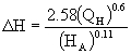
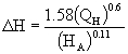
| STEP 3: | Calculate plume rise utilizing the appropriate formula given below and the total heat emission rate obtained in Step 2: |
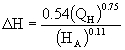
H = 2.58 (Q)0.6 for Q 6000 btu/sec.
(X)0.11
 (in English Units for QH≥ 6000 btu/sec)
 (in Metric Units for QH≥ 1500 kcal/sec)
H = 0.718 (Q)0.75 for Q 6000 btu/sec.
(X)0.11
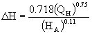 (in English Units for QH< 6000 btu/sec)
 (in Metric Units for QH< 1500 kcal/sec)
| STEP 4: | Calculate the weighted average facility effective height of effluent release utilizing the plume rise obtained in Step 3, the average stack height obtained in Step 1 and the formula given below: |
Y = X + H
| HE = HA + ∆H | |
| STEP 5: | Calculate the total facility hourly emission limitation utilizing the weighted actual stack height obtained in Step 1, the effective stack height given in Step 4, and the following formula: |
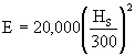
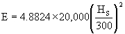
E = (X)0.11 (Y)2
128
![]() (in English units)
(in English units)
![]() (in Metric units)
(in Metric units)
(Source: Amended at _ Ill. Reg. _, effective _)
TITLE 35: ENVIRONMENTAL PROTECTION
SUBTITLE B: AIR POLLUTION
CHAPTER I: POLLUTION CONTROL BOARD
SUBCHAPTER c: EMISSIONS STANDARDS AND
LIMITATIONS FOR STATIONARY SOURCES
PART 218
ORGANIC MATERIAL EMISSION STANDARDS AND
LIMITATIONS FOR THE CHICAGO AREA
SUBPART A: GENERAL PROVISIONS
Section
| 218.100 | Introduction |
| 218.101 | Savings Clause |
| 218.102 | Abbreviations and Conversion Factors |
| 218.103 | Applicability |
| 218.104 | Definitions |
| 218.105 | Test Methods and Procedures |
| 218.106 | Compliance Dates |
| 218.107 | Operation of Afterburners |
| 218.108 | Exemptions, Variations, and Alternative Means of Control or Compliance Determinations |
| 218.109 | Vapor Pressure of Volatile Organic Liquids |
| 218.110 | Vapor Pressure of Organic Material or Solvent |
| 218.111 | Vapor Pressure of Volatile Organic Material |
| 218.112 | Incorporations by Reference |
| 218.113 | Monitoring for Negligibly-Reactive Compounds |
| 218.114 | Compliance with Permit Conditions |
SUBPART B: ORGANIC EMISSIONS FROM STORAGE AND LOADING OPERATIONS
Section
| 218.119 | Applicability for VOL |
| 218.120 | Control Requirements for Storage Containers of VOL |
| 218.121 | Storage Containers of VPL |
| 218.122 | Loading Operations |
| 218.123 | Petroleum Liquid Storage Tanks |
| 218.124 | External Floating Roofs |
| 218.125 | Compliance Dates |
| 218.126 | Compliance Plan (Repealed) |
| 218.127 | Testing VOL Operations |
| 218.128 | Monitoring VOL Operations |
| 218.129 | Recordkeeping and Reporting for VOL Operations |
SUBPART C: ORGANIC EMISSIONS FROM MISCELLANEOUS EQUIPMENT
Section
| 218.141 | Separation Operations |
| 218.142 | Pumps and Compressors |
| 218.143 | Vapor Blowdown |
| 218.144 | Safety Relief Valves |
SUBPART E: SOLVENT CLEANING
Section
| 218.181 | Solvent Cleaning in General |
| 218.182 | Cold Cleaning |
| 218.183 | Open Top Vapor Degreasing |
| 218.184 | Conveyorized Degreasing |
| 218.185 | Compliance Schedule (Repealed) |
| 218.186 | Test Methods |
SUBPART F: COATING OPERATIONS
Section
| 218.204 | Emission Limitations |
| 218.205 | Daily-Weighted Average Limitations |
| 218.206 | Solids Basis Calculation |
| 218.207 | Alternative Emission Limitations |
| 218.208 | Exemptions from Emission Limitations |
| 218.209 | Exemption from General Rule on Use of Organic Material |
| 218.210 | Compliance Schedule |
| 218.211 | Recordkeeping and Reporting |
| 218.212 | Cross-Line Averaging to Establish Compliance for Coating Lines |
| 218.213 | Recordkeeping and Reporting for Cross-Line Averaging Participating Coating Lines |
| 218.214 | Changing Compliance Methods |
218.215 Wood Furniture Coating Averaging Approach
218.216 Wood Furniture Coating Add-On Control Use
218.217 Wood Furniture Coating Work Practice Standards
SUBPART G: USE OF ORGANIC MATERIAL
Section
| 218.301 | Use of Organic Material |
| 218.302 | Alternative Standard |
| 218.303 | Fuel Combustion Emission Units |
| 218.304 | Operations with Compliance Program |
SUBPART H: PRINTING AND PUBLISHING
Section
| 218.401 | Flexographic and Rotogravure Printing |
| 218.402 | Applicability |
| 218.403 | Compliance Schedule |
| 218.404 | Recordkeeping and Reporting |
| 218.405 | Lithographic Printing: Applicability |
| 218.406 | Provisions Applying to Heatset Web Offset Lithographic Printing Prior to March 15, 1996 |
| 218.407 | Emission Limitations and Control Requirements for Lithographic Printing Lines On and After March 15, 1996 |
| 218.408 | Compliance Schedule for Lithographic Printing On and After March 15, 1996 |
| 218.409 | Testing for Lithographic Printing On and After March 15, 1996 |
| 218.410 | Monitoring Requirements for Lithographic Printing |
| 218.411 | Recordkeeping and Reporting for Lithographic Printing |
SUBPART Q: SYNTHETIC ORGANIC CHEMICAL AND POLYMER MANUFACTURING PLANT
Section
| 218.421 | General Requirements |
| 218.422 | Inspection Program Plan for Leaks |
| 218.423 | Inspection Program for Leaks |
| 218.424 | Repairing Leaks |
| 218.425 | Recordkeeping for Leaks |
| 218.426 | Report for Leaks |
| 218.427 | Alternative Program for Leaks |
| 218.428 | Open-Ended Valves |
| 218.429 | Standards for Control Devices |
| 218.430 | Compliance Date (Repealed) |
| 218.431 | Applicability |
| 218.432 | Control Requirements |
| 218.433 | Performance and Testing Requirements |
| 218.434 | Monitoring Requirements |
| 218.435 | Recordkeeping and Reporting Requirements |
| 218.436 | Compliance Date |
SUBPART R: PETROLEUM REFINING AND RELATED INDUSTRIES; ASPHALT MATERIALS
Section
| 218.441 | Petroleum Refinery Waste Gas Disposal |
| 218.442 | Vacuum Producing Systems |
| 218.443 | Wastewater (Oil/Water) Separator |
| 218.444 | Process Unit Turnarounds |
| 218.445 | Leaks: General Requirements |
| 218.446 | Monitoring Program Plan for Leaks |
| 218.447 | Monitoring Program for Leaks |
| 218.448 | Recordkeeping for Leaks |
| 218.449 | Reporting for Leaks |
| 218.450 | Alternative Program for Leaks |
| 218.451 | Sealing Device Requirements |
| 218.452 | Compliance Schedule for Leaks |
| 218.453 | Compliance Dates (Repealed) |
SUBPART S: RUBBER AND MISCELLANEOUS PLASTIC PRODUCTS
Section
| 218.461 | Manufacture of Pneumatic Rubber Tires |
| 218.462 | Green Tire Spraying Operations |
| 218.463 | Alternative Emission Reduction Systems |
| 218.464 | Emission Testing |
| 218.465 | Compliance Dates (Repealed) |
| 218.466 | Compliance Plan (Repealed) |
SUBPART T: PHARMACEUTICAL MANUFACTURING
Section
| 218.480 | Applicability |
| 218.481 | Control of Reactors, Distillation Units, Crystallizers, Centrifuges and Vacuum Dryers |
| 218.482 | Control of Air Dryers, Production Equipment Exhaust Systems and Filters |
| 218.483 | Material Storage and Transfer |
| 218.484 | In-Process Tanks |
| 218.485 | Leaks |
| 218.486 | Other Emission Units |
| 218.487 | Testing |
| 218.488 | Monitoring for Air Pollution Control Equipment |
| 218.489 | Recordkeeping for Air Pollution Control Equipment |
SUBPART V: BATCH OPERATIONS AND AIR OXIDATION PROCESSES
Section
| 218.500 | Applicability for Batch Operations |
| 218.501 | Control Requirements for Batch Operations |
| 218.502 | Determination of Uncontrolled Total Annual Mass Emissions and Average Flow Rate Values for Batch Operations |
| 218.503 | Performance and Testing Requirements for Batch Operations |
| 218.504 | Monitoring Requirements for Batch Operations |
| 218.505 | Reporting and Recordkeeping for Batch Operations |
| 218.506 | Compliance Date |
| 218.520 | Emission Limitations for Air Oxidation Processes |
| 218.521 | Definitions (Repealed) |
| 218.522 | Savings Clause |
| 218.523 | Compliance |
| 218.524 | Determination of Applicability |
| 218.525 | Emission Limitations for Air Oxidation Processes |
| 218.526 | Testing and Monitoring |
| 218.527 | Compliance Date (Repealed) |
SUBPART W: AGRICULTURE
Section
| 218.541 | Pesticide Exception |
SUBPART X: CONSTRUCTION
Section
| 218.561 | Architectural Coatings |
| 218.562 | Paving Operations |
| 218.563 | Cutback Asphalt |
SUBPART Y: GASOLINE DISTRIBUTION
Section
| 218.581 | Bulk Gasoline Plants |
| 218.582 | Bulk Gasoline Terminals |
| 218.583 | Gasoline Dispensing Operations - Storage Tank Filling Operations |
| 218.584 | Gasoline Delivery Vessels |
| 218.585 | Gasoline Volatility Standards |
| 218.586 | Gasoline Dispensing Operations - Motor Vehicle Fueling Operations |
SUBPART Z: DRY CLEANERS
Section
| 218.601 | Perchloroethylene Dry Cleaners (Repealed) |
| 218.602 | Applicability (Repealed) |
| 218.603 | Leaks (Repealed) |
| 218.604 | Compliance Dates (Repealed) |
| 218.605 | Compliance Plan (Repealed) |
| 218.606 | Exception to Compliance Plan (Repealed) |
| 218.607 | Standards for Petroleum Solvent Dry Cleaners |
| 218.608 | Operating Practices for Petroleum Solvent Dry Cleaners |
| 218.609 | Program for Inspection and Repair of Leaks |
| 218.610 | Testing and Monitoring |
| 218.611 | Applicability for Petroleum Solvent Dry Cleaners |
| 218.612 | Compliance Dates (Repealed) |
| 218.613 | Compliance Plan (Repealed) |
SUBPART AA: PAINT AND INK MANUFACTURING
Section
| 218.620 | Applicability |
| 218.621 | Exemption for Waterbase Material and Heatset Offset Ink |
| 218.623 | Permit Conditions (Repealed) |
| 218.624 | Open Top Mills, Tanks, Vats or Vessels |
| 218.625 | Grinding Mills |
| 218.626 | Storage Tanks |
| 218.628 | Leaks |
| 218.630 | Clean Up |
| 218.636 | Compliance Schedule |
| 218.637 | Recordkeeping and Reporting |
SUBPART BB: POLYSTYRENE PLANTS
Section
| 218.640 | Applicability |
| 218.642 | Emissions Limitation at Polystyrene Plants |
| 218.644 | Emissions Testing |
SUBPART CC: POLYESTER RESIN PRODUCT MANUFACTURING PROCESS
Section
| 218.660 | Applicability |
| 218.666 | Control Requirements |
| 218.667 | Compliance Schedule |
| 218.668 | Testing |
| 218.670 | Recordkeeping and Reporting for Exempt Emission Units |
| 218.672 | Recordkeeping and Reporting for Subject Emission Units |
SUBPART DD: AEROSOL CAN FILLING
Section
| 218.680 | Applicability |
| 218.686 | Control Requirements |
| 218.688 | Testing |
| 218.690 | Recordkeeping and Reporting for Exempt Emission Units |
| 218.692 | Recordkeeping and Reporting for Subject Emission Units |
SUBPART FF: BAKERY OVENS (REPEALED)
Section
| 218.720 | Applicability (Repealed) |
| 218.722 | Control Requirements (Repealed) |
| 218.726 | Testing (Repealed) |
| 218.727 | Monitoring (Repealed) |
| 218.728 | Recordkeeping and Reporting (Repealed) |
| 218.729 | Compliance Date (Repealed) |
| 218.730 | Certification (Repealed) |
SUBPART GG: MARINE TERMINALS
Section
| 218.760 | Applicability |
| 218.762 | Control Requirements |
| 218.764 | Compliance Certification |
| 218.766 | Leaks |
| 218.768 | Testing and Monitoring |
| 218.770 | Recordkeeping and Reporting |
SUBPART HH: MOTOR VEHICLE REFINISHING
Section
| 218.780 | Emission Limitations |
| 218.782 | Alternative Control Requirements |
| 218.784 | Equipment Specifications |
| 218.786 | Surface Preparation Materials |
| 218.787 | Work Practices |
| 218.788 | Testing |
| 218.789 | Monitoring and Recordkeeping for Control Devices |
| 218.790 | General Recordkeeping and Reporting (Repealed) |
| 218.791 | Compliance Date |
| 218.792 | Registration |
| 218.875 | Applicability of Subpart BB (Renumbered) |
| 218.877 | Emissions Limitation at Polystyrene Plants (Renumbered) |
| 218.879 | Compliance Date (Repealed) |
| 218.881 | Compliance Plan (Repealed) |
| 218.883 | Special Requirements for Compliance Plan (Repealed) |
| 218.886 | Emissions Testing (Renumbered) |
SUBPART PP: MISCELLANEOUS FABRICATED PRODUCT MANUFACTURING PROCESSES
Section
| 218.920 | Applicability |
| 218.923 | Permit Conditions (Repealed) |
| 218.926 | Control Requirements |
| 218.927 | Compliance Schedule |
| 218.928 | Testing |
218.929 Cementable and Dress or Performance Shoe Leather
SUBPART QQ: MISCELLANEOUS FORMULATION MANUFACTURING PROCESSES
Section
| 218.940 | Applicability |
| 218.943 | Permit Conditions (Repealed) |
| 218.946 | Control Requirements |
| 218.947 | Compliance Schedule |
| 218.948 | Testing |
SUBPART RR: MISCELLANEOUS ORGANIC CHEMICAL MANUFACTURING PROCESSES
Section
| 218.960 | Applicability |
| 218.963 | Permit Conditions (Repealed) |
| 218.966 | Control Requirements |
| 218.967 | Compliance Schedule |
| 218.968 | Testing |
SUBPART TT: OTHER EMISSION UNITS
Section
| 218.980 | Applicability |
| 218.983 | Permit Conditions (Repealed) |
| 218.986 | Control Requirements |
| 218.987 | Compliance Schedule |
| 218.988 | Testing |
SUBPART UU: RECORDKEEPING AND REPORTING
Section
| 218.990 | Exempt Emission Units |
| 218.991 | Subject Emission Units |
| Section 218.Appendix A: | |
| List of Chemicals Defining Synthetic Organic Chemical and Polymer Manufacturing | |
| Section 218.Appendix B: | |
| VOM Measurement Techniques for Capture Efficiency (Repealed) |
| Section 218.Appendix C: | |
| Reference Methods and Procedures |
| Section 218.Appendix D: | |
| Coefficients for the Total Resource Effectiveness Index (TRE) Equation |
| Section 218.Appendix E: | |
| List of Affected Marine Terminals |
| Section 218.Appendix G: | |
| TRE Index Measurements for SOCMI Reactors and Distillation Units | |
| Section 218.Appendix H: | |
| Baseline VOM Content Limitations for Subpart F, Section 218.212 Cross-Line Averaging | |
AUTHORITY: Implementing Section 10 and authorized by Sections 27, 28, 28.5 of the Environmental Protection Act [415 ILCS 5/10 and 28.5].
SOURCE: Adopted at R91-7 at 15 Ill. Reg. 12231, effective August 16, 1991; amended in R91-24 at 16 Ill. Reg. 13564, effective August 24, 1992; amended in R91-28 and R91-30 at 16 Ill. Reg. 13864, effective August 24, 1992; amended in R93-9 at 17 Ill. Reg. 16636, effective September 27, 1993; amended in R93-14 at 18 Ill. Reg. at 1945, effective January 24, 1994; amended in R94-12 at 18 Ill. Reg. at 14973, effective September 21, 1994; amended in R94-15 at 18 Ill. Reg. 16392, effective October 25, 1994; amended in R94-16 at 18 Ill. Reg. 16950, effective November 15, 1994; amended in R94-21, R94-31 and R94-32 at 19 Ill. Reg. 6848, effective May 9, 1995; amended in R94-33 at 19 Ill. Reg. 7359, effective May 22, 1995; amended in R96-13 at 20 Ill. Reg. 14428, effective October 17, 1996; amended in R97-24 at 21 Ill. Reg. 7708, effective June 9, 1997; amended in R97-31 at 22 Ill. Reg. 3556, effective February 2, 1998; amended in R98-16 at 22 Ill. Reg. 14282, effective July 16, 1998; amended in R02-20, at 27 Ill. Reg 7283, effective April 8, 2003; amended in R04-20 at _ Ill. Reg. _, effective _.
BOARD NOTE: This Part implements the Environmental Protection Act as of July 1, 1994.
SUBPART A: GENERAL PROVISIONS
Section 218.105 Test Methods and Procedures
| a) | Coatings, Inks and Fountain Solutions |
The following test methods and procedures shall be used to determine compliance of as applied coatings, inks, and fountain solutions with the limitations set forth in this Part.
| 1) | Sampling: Samples collected for analyses shall be one-liter taken into a one-liter container at a location and time such that the sample will be representative of the coating as applied (i.e., the sample shall include any dilution solvent or other VOM added during the manufacturing process). The container must be tightly sealed immediately after the sample is taken. Any solvent or other VOM added after the sample is taken must be measured and accounted for in the calculations in subsection (a)(3) of this Section. For multiple package coatings, separate samples of each component shall be obtained. A mixed sample shall not be obtained as it will cure in the container. Sampling procedures shall follow the guidelines presented in: |
| A) | ASTM D3925-81 (1985) standard practice for sampling liquid paints and related pigment coating. This practice is incorporated by reference in Section 218.112 of this Part. |
| B) | ASTM E300-86 standard practice for sampling industrial chemicals. This practice is incorporated by reference in Section 218.112 of this Part. |
| 2) | Analyses: The applicable analytical methods specified below shall be used to determine the composition of coatings, inks, or fountain solutions as applied. |
| A) | Method 24 of 40 CFR 60, Appendix A, incorporated by reference in Section 218.112 of this Part, shall be used to determine the VOM content and density of coatings. If it is demonstrated to the satisfaction of the Agency and the USEPA that plant coating formulation data are equivalent to Method 24 results, formulation data may be used. In the event of any inconsistency between a Method 24 test and a facility's formulation data, the Method 24 test will govern. |
| B) | Method 24A of 40 CFR Part 60, Appendix A, incorporated by reference in Section 218.112 of this Part, shall be used to determine the VOM content and density of rotogravure printing inks and related coatings. If it is demonstrated to the satisfaction of the Agency and USEPA that the plant coating formulation data are equivalent to Method 24A results, formulation data may be used. In the event of any inconsistency between a Method 24A test and formulation data, the Method 24A test will govern. |
| C) | The following ASTM methods are the analytical procedures for determining VOM: |
| i) | ASTM D1475-85: Standard test method for density of paint, varnish, lacquer and related products. This test method is incorporated by reference in Section 218.112 of this Part. |
| ii) | ASTM D2369-87: Standard test method for volatile content of a coating. This test method is incorporated by reference in Section 218.112 of this Part. |
| iii) | ASTM D3792-86: Standard test method for water content of water-reducible paints by direct injection into a gas chromatograph. This test method is incorporated by reference in Section 218.112 of this Part. |
| iv) | ASTM D4017-81 (1987): Standard test method for water content in paints and paint materials by the Karl Fischer method. This test method is incorporated by reference in Section 218.112 of this Part. |
| v) | ASTM D4457-85: Standard test method for determination of dichloromethane and 1,1,1, trichloroethane in paints and coatings by direct injection into a gas chromatograph. (The procedure delineated above can be used to develop protocols for any compounds specifically exempted from the definition of VOM.) This test method is incorporated by reference in Section 218.112 of this Part. |
| vi) | ASTM D2697-86: Standard test method for volume non-volatile matter in clear or pigmented coatings. This test method is incorporated by reference in Section 218.112 of this Part. |
| vii) | ASTM D3980-87: Standard practice for interlaboratory testing of paint and related materials. This practice is incorporated by reference in Section 218.112 of this Part. |
| viii) | ASTM E180-85: Standard practice for determining the precision data of ASTM methods for analysis of and testing of industrial chemicals. This practice is incorporated by reference in Section 218.112 of this Part. |
| ix) | ASTM D2372-85: Standard method of separation of vehicle from solvent-reducible paints. This method is incorporated by reference in Section 218.112 of this Part. |
| D) | Use of an adaptation to any of the analytical methods specified in subsections (a)(2)(A), (B), and (C) of this Section may not be used unless approved by the Agency and USEPA. An owner or operator must submit sufficient documentation for the Agency and USEPA to find that the analytical methods specified in subsections (a)(2)(A), (B), and (C) of this Section will yield inaccurate results and that the proposed adaptation is appropriate. |
| 3) | Calculations: Calculations for determining the VOM content, water content and the content of any compounds which are specifically exempted from the definition of VOM of coatings, inks and fountain solutions as applied shall follow the guidance provided in the following documents: |
| A) | “A Guide for Surface Coating Calculation”, EPA-340/1-86-016, incorporated by reference in Section 218.112 of this Part. |
| B) | “Procedures for Certifying Quantity of Volatile Organic Compounds Emitted by Paint, Ink and Other Coatings” (revised June 1986), EPA-450/3-84-019, incorporated by reference in Section 218.112 of this Part. |
| C) | “A Guide for Graphic Arts Calculations”, August 1988, EPA-340/1-88-003, incorporated by reference in Section 218.112 of this Part. |
| b) | Automobile or Light-Duty Truck Test Protocol |
| 1) | The protocol for testing, including determining the transfer efficiency of coating applicators, at primer surfacer operations and topcoat operations at an automobile or light-duty truck assembly source shall follow the procedures in: "Protocol for Determining the Daily Volatile Organic Compound Emission Rate of Automobile and Light-Duty Truck Topcoat Operations" ("topcoat protocol"), December 1988, EPA-450/3-88-018, incorporated by reference in Section 218.112 of this Part. |
| 2) | Prior to testing pursuant to the topcoat protocol, the owner or operator of a coating operation subject to the topcoat or primer surfacer limit in Sections 218.204(a)(2) or 218.204(a)(3) shall submit a detailed testing proposal specifying the method by which testing will be conducted and how compliance will be demonstrated consistent with the topcoat protocol. The proposal shall include, at a minimum, a comprehensive plan (including a rationale) for determining the transfer efficiency at each booth through the use of in-plant or pilot testing, the selection of coatings to be tested (for the purpose of determining transfer efficiency) including the rationale for coating groupings, the method for determining the analytic VOM content of as applied coatings and the formulation solvent content of as applied coatings, and a description of the records of coating VOM content as applied and coating's usage which will be kept to demonstrate compliance. Upon approval of the proposal by the Agency and USEPA, the compliance demonstration for a coating line may proceed. |
| c) | Capture System Efficiency Test Protocols |
| 1) | Applicability |
The requirements of subsection (c)(2) of this Section shall apply to all VOM emitting process emission units employing capture equipment (e.g., hoods, ducts), except those cases noted below.
| A) | If an emission unit is equipped with (or uses) a permanent total enclosure (PTE) that meets Agency and USEPA specifications, and which directs all VOM to a control device, then the emission unit is exempted from the requirements described in subsection (c)(2) of this Section. The Agency and USEPA specifications to determine whether a structure is considered a PTE are given in Method 204 |
| B) | If an emission unit is equipped with (or uses) a control device designed to collect and recover VOM (e.g., carbon adsorber), an explicit measurement of capture efficiency is not necessary provided that the conditions given below are met. The overall control of the system can be determined by directly comparing the input liquid VOM to the recovered liquid VOM. The general procedure for use in this situation is given in 40 CFR 60.433, incorporated by reference in Section 218.112 of this Part, with the following additional restrictions: |
| i) | Unless otherwise specified in subsection (c)(1)(B)(ii) below, the owner or operator shall obtain data each operating day for the solvent usage and solvent recovery to permit the determination of the solvent recovery efficiency of the system each operating day using a 7-day rolling period. The recovery efficiency for each operating day is computed as the ratio of the total recovered solvent for that day and the most recent prior 6 operating days to the total solvent usage for the same 7-day period used for the recovered solvent, rather than a 30-day weighted average as given in 40 CFR 60.433 incorporated by reference at Section 218.112 of this Part. This ratio shall be expressed as a percentage. The ratio shall be computed within 72 hours following each 7-day period. A source that believes that the 7-day rolling period is not appropriate may use an alterative multi-day rolling period not to exceed 30 days, with the approval of the Agency and USEPA. In addition, the criteria in subsection (c)(1)(B)(iii) or subsection (c)(1)(B)(iv) below must be met. |
| ii) | The owner or operator of the source engaged in printing located at 350 E. 22nd Street, Chicago, Illinois, shall obtain data each operating day for the solvent usage and solvent recovery to permit the determination of the solvent recovery efficiency of the system each operating day using a 14-day rolling period. The recovery efficiency for each operating day is computed as the ratio of the total recovered solvent for that day and the most recent prior 13 operating days to the total solvent usage for the same 14-day period used for the recovered solvent, rather than a 30-day weighted average as given in 40 CFR 60.433, incorporated by reference in Section 218.112 of this Part. This ratio shall be expressed as a percentage. The ratio shall be computed within 17 days following each 14-day period. In addition, the criteria in subsection (c)(1)(B)(iii) or subsection (c)(1)(B)(iv) below must be met. |
| iii) | The solvent recovery system (i.e., capture and control system) must be dedicated to a single coating line, printing line, or other discrete activity that by itself is subject to an applicable VOM emission standard, or |
| iv) | If the solvent recovery system controls more than one coating line, printing line or other discrete activity that by itself is subject to an applicable VOM emission standard, the overall control (i.e. the total recovered VOM divided by the sum of liquid VOM input from all lines and other activities venting to the control system) must meet or exceed the most stringent standard applicable to any line or other discrete activity venting to the control system. |
| 2) | Capture Efficiency Protocols |
| The capture efficiency of an emission unit shall be measured using one of the | ||||
| A) | Gas/gas method using temporary total enclosure (TTE). The Agency and USEPA specifications to determine whether a temporary enclosure is considered a TTE are given in Method 204 |
CE = Gww/(Gww + Fww)
where:
CE = Capture efficiency, decimal fraction;
Gww = Mass of VOM captured and delivered to control device using a TTE;
Fww = Mass of uncaptured fugitive VOM that escapes from
a TTE.
Method 204B or 204C Procedure G.2 contained in Appendix M of 40 CFR Part 51, incorporated by reference in Section 218.112 of this Part Appendix B of this Part is used to obtain Gww. Method 204D Procedure F.1 in Appendix B in Appendix M of 40 CFR Part 51, incorporated by reference in Section 218.112 of this Part of this Part, is used to obtain Fww.
| B) | Liquid/gas method using TTE. The Agency and USEPA specifications to determine whether a temporary enclosure is considered a TTE are given in Method 204 |
CE = (L - Fww) /L
where:
CE = Capture efficiency, decimal fraction;
L = Mass of liquid VOM input to process emission unit;
Fww = Mass of uncaptured fugitive VOM that escapes from
a TTE.
| Method 204A or 204F | |||||
| C) | Gas/gas method using the building or room (building or room enclosure), in which the affected coating line, printing line or other emission unit is located, as the enclosure as determined by Method 204 of Appendix M of 40 CFR Part 51, incorporated by reference in Section 218.112 of this Part, and in which "FB" |
| CE = G/(G +FB) | |
| where: | |
| CE = Capture efficiency, decimal fraction; | |
G = Mass of VOM captured and delivered to control
device;
FB = Mass of uncaptured fugitive VOM that escapes from
building enclosure.
| Method 204B or 204C | |||||
| D) | Liquid/gas method using the building or room (building or room enclosure), in which the affected coating line, printing line or other emission unit is located, as the enclosure as determined by Method 204 of Appendix M of 40 CFR Part 51, incorporated by reference in Section 218.112 of this Part, and in which "FB" |
| CE = (L - FB) /L | |
| where: | |
| CE = Capture efficiency, decimal fraction; | |
| L = Mass of liquid VOM input to process emission unit; | |
FB = Mass of uncaptured fugitive VOM that escapes from
building enclosure.
Method 204A or 204F Procedure L contained in Appendix B of this Part Appendix M of 40 CFR Part 51, incorporated by reference in Section 218.112 of this Part is used to obtain L. Method 204E Procedure F.2 in Appendix B of this Part Appendix M of 40 CFR Part 51, incorporated by reference in Section 218.112 of this Part is used to obtain FB.
| E) | Mass balance using Data Quality Objective (DQO) or Lower Confidence Limit (LCL) protocol. For a liquid/gas input where an owner or operator is using the DQO/LCL protocol and not using an enclosure as described in Method 204 of Appendix M of 40 CFR Part 51, incorporated by reference in Section 218.112 of this Part, the VOM content of the liquid input (L) must be determined using Method 204A or 204F in Appendix M of 40 CFR Part 51, incorporated by reference in Section 218.112 of this Part. The VOM content of the captured gas stream (G) to the control device must be determined using Method 204B or 204C in Appendix M of 40 CFR Part 51. The results of capture efficiency calculations (G/L) must satisfy the DQO or LCL statistical analysis protocol as described in Section 3 of USEPA’s “Guidelines for Determining Capture Efficiency,” incorporated by reference at 218.112 of this Part. Where capture efficiency testing is done to determine emission reductions for the purpose of establishing emission credits for offsets, shutdowns, and trading, the LCL protocol cannot be used for these applications. In enforcement cases, the LCL protocol cannot confirm non-compliance; capture efficiency must be determined using a protocol under subsection (c)(2)(A), (B), (C) or (D) of this Section, the DQO protocol of this subsection (c)(2)(E), or an alternative protocol pursuant to Section 218.108(b) of this Part. | ||
| BOARD NOTE: Where LCL was used in testing emission units that are the subject of later requests for establishing emission credits for offsets, shutdowns, and trading, prior LCL results may not be relied upon to determine the appropriate amount of credits. Instead, to establish the appropriate amount of credits, additional testing may be required that would satisfy the protocol of Section 218.105(c)(2)(A), (B), (C) or (D), the DQO protocol of Section 218.105(c)(2)(E), or an alternative protocol pursuant to Section 218.108(b) of this Part. | ||||
| 3) | Simultaneous testing of multiple lines or emission units with a common control device. If an owner or operator has multiple lines sharing a common control device, the capture efficiency of the lines may be tested simultaneously, subject to the following provisions: |
| A) | Multiple line testing must meet the criteria of Section 4 of USEPA’s “Guidelines for Determining Capture Efficiency,” incorporated by reference at Section 218.112 of this Part; |
| B) | The most stringent capture efficiency required for any individual line or unit must be met by the aggregate of lines or units; and |
| C) | Testing of all the lines of emission units must be performed with the same capture efficiency test protocol. |
| 4) | Recordkeeping and Reporting |
| A) | All owners or operators affected by this subsection must maintain a copy of the capture efficiency protocol submitted to the Agency and the USEPA on file. All results of the appropriate test methods and capture efficiency protocols must be reported to the Agency within |
| B) | If any changes are made to capture or control equipment, then the source is required to notify the Agency and the USEPA of these changes and a new test may be required by the Agency or the USEPA. |
| C) | The source must notify the Agency 30 days prior to performing any capture efficiency or control test. At that time, the source must notify the Agency which capture efficiency protocol and control device test methods will be used. Notification of the actual date and expected time of testing must be submitted a minimum of 5 working days prior to the actual date of the test. The Agency may at its discretion accept notification with shorter advance notice provided that such arrangements do not interfere with the Agency’s ability to review the protocol or observe testing. |
| D) | Sources utilizing a PTE must demonstrate that this enclosure meets the requirements given in Method 204 |
| E) | Sources utilizing a TTE must demonstrate that their TTE meets the requirements given in Method 204 |
| F) | Any source utilizing the DQO or LCL protocol must submit the following information to the Agency with each test report: | |||
| i) | A copy of all test methods, Quality Assurance/Quality Control procedures, and calibration procedures to be used from those described in Appendix M of 40 CFR Part 51, incorporated by reference in Section 218.112 of this Part; | ||||
| ii) | A table with information on each sample taken, including the sample identification and the VOM content of the sample; |
| iii) | The quantity of material used for each test run; | |||
| iv) | The quantity of captured VOM for each test run; | |||
| v) | The capture efficiency calculations and results for each test run; | |||
| vi) | The DQO and/or LCL calculations and results; and | |||
| vii) | The Quality Assurance/Quality Control results, including how often the instruments were calibrated, the calibration results, and the calibration gases used. | |||
| d) | Control Device Efficiency Testing and Monitoring |
| 1) | The control device efficiency shall be determined by simultaneously measuring the inlet and outlet gas phase VOM concentrations and gas volumetric flow rates in accordance with the gas phase test methods specified in subsection (f) of this Section. |
| 2) | An owner or operator: |
| A) | That uses an afterburner or carbon adsorber to comply with any Section of Part 218 shall use Agency and USEPA approved continuous monitoring equipment which is installed, calibrated, maintained, and operated according to vendor specifications at all times the |
| i) | For each afterburner which does not have a catalyst bed, the combustion chamber temperature of each afterburner. |
| ii) | For each afterburner which has a catalyst bed, commonly known as a catalytic afterburner, the temperature rise across each catalytic afterburner bed or VOM concentration of exhaust. |
| iii) | For each carbon adsorber, the VOM concentration of each carbon adsorption bed exhaust or the exhaust of the bed next in sequence to be desorbed. |
| B) | Must install, calibrate, operate and maintain, in accordance with manufacturer’s specifications, a continuous recorder on the temperature monitoring device, such as a strip chart, recorder or computer, having an accuracy of ± 1 percent of the temperature measured in degrees Celsius or ± 0.5o C, whichever is greater. | ||
| C | Of an automobile or light-duty truck primer surfacer operation or topcoat operation subject to subsection (d)(2)(A) above, shall keep a separate record of the following data for the control devices, unless alternative provisions are set forth in a permit pursuant to Title V of the Clean Air Act: |
| i) | For thermal afterburners for which combustion chamber temperature is monitored, all 3-hour periods of operation in which the average combustion temperature was more than 28oC (50oF) below the average combustion temperature measured during the most recent performance test that demonstrated that the operation was in compliance. |
| ii) | For catalytic afterburners for which temperature rise is monitored, all 3-hour periods of operation in which the average gas temperature before the catalyst bed is more than 28oC (50oF) below the average gas temperature immediately before the catalyst bed measured during the most recent performance test that demonstrated that the operation was in compliance. |
| iii) | For catalytic afterburners and carbon adsorbers for which VOM concentration is monitored, all 3-hour periods of operation during which the average VOM concentration or the reading of organics in the exhaust gases is more than 20 percent greater than the average exhaust gas concentration or reading measured by the organic monitoring device during the most recent determination of the recovery efficiency of a carbon adsorber or performance test for a catalytic afterburner, which determination or test demonstrated that the operation was in compliance. |
| 3) | An owner or operator that uses a carbon adsorber to comply with Section 218.401 of this Part may operate the adsorber during periods of monitoring equipment malfunction, provided that: |
| A) | The owner or operator notifies in writing the Agency within, 10 days after the conclusion of any 72 hour period during which the adsorber is operated and the associated monitoring equipment is not operational, of such monitoring equipment failure and provides the duration of the malfunction, a description of the repairs made to the equipment, and the total to date of all hours in the calendar year during which the adsorber was operated and the associated monitoring equipment was not operational; |
| B) | During such period of malfunction the adsorber is operated using timed sequences as the basis for periodic regeneration of the adsorber; |
| C) | The period of such adsorber operation does not exceed 360 hours in any calendar year without the approval of the Agency and USEPA; and |
| D) | The total of all hours in the calendar year during which the adsorber was operated and the associated monitoring equipment was not operational shall be reported, in writing, to the Agency and USEPA by January 31st of the following calendar year. |
| e) | Overall Efficiency |
| 1) | The overall efficiency of the emission control system shall be determined as the product of the capture system efficiency and the control device efficiency or by the liquid/liquid test protocol as specified in 40 CFR 60.433, incorporated by reference in Section 218.112 of this Part, (and revised by subsection (c)(1)(B) of this Section) for each solvent recovery system. In those cases in which the overall efficiency is being determined for an entire line, the capture efficiency used to calculate the product of the capture and control efficiency is the total capture efficiency over the entire line. |
| 2) | For coating lines which are both chosen by the owner or operator to comply with Section 218.207(c), (d), (e), (f), or (g) of this Part by the alternative in Section 218.207(b)(2) of this Part and meet the criteria allowing them to comply with Section 218.207 of this Part instead of Section 218.204 of this Part, the overall efficiency of the capture system and control device, as determined by the test methods and procedures specified in subsections (c), (d) and (e)(1) of this Section, shall be no less than the equivalent overall efficiency which shall be calculated by the following equation: |
| E = ([VOMa - VOM1]/VOMa) x 100 | |
| where: | |
| E = | Equivalent overall efficiency of the capture system and control device as a percentage; |
| VOMa = | Actual VOM content of a coating, or the daily-weighted average VOM content of two or more coatings (if more than one coating is used), as applied to the subject coating line as determined by the applicable test methods and procedures specified in subsection (a) of this Section in units of kg VOM/l (lb VOM/gal) of coating solids as applied; |
| VOM1 = | The VOM emission limit specified in Section 218.204 or 218.205 of this Part in units of kg VOM/l (lb VOM/gal) of coating solids as applied |
| f) | Volatile Organic Material Gas Phase Source Test Methods. The methods in 40 CFR Part 60, Appendix A, incorporated by reference in Section 218.112 of this Part delineated below shall be used to determine control device efficiencies. |
| 1) | 40 CFR Part 60, Appendix A, Method 18, 25 or 25A, incorporated by reference in Section 218.112 of this Part as appropriate to the conditions at the site, shall be used to determine VOM concentration. Method selection shall be based on consideration of the diversity of organic species present and their total concentration and on consideration of the potential presence of interfering gases. Except as indicated in subsections (f)(1)(A) and (B) below, the test shall consist of three separate runs, each lasting a minimum of 60 minutes, unless the Agency and the USEPA determine that process variables dictate shorter sampling times. |
| A) | When the method is to be used to determine the efficiency of a carbon adsorption system with a common exhaust stack for all the individual adsorber vessels, the test shall consist of three separate runs, each coinciding with one or more complete sequences through the adsorption cycles of all the individual absorber vessels. |
| B) | When the method is to be used to determine the efficiency of a carbon adsorption system with individual exhaust stacks for each absorber vessel, each adsorber vessel shall be tested individually. The test for each absorber vessel shall consist of three separate runs. Each run shall coincide with one or more complete adsorption cycles. |
| 2) | 40 CFR Part 60, Appendix A, Method 1 or 1A, incorporated by reference in Section 218.112 of this Part, shall be used for sample and velocity traverses. |
| 3) | 40 CFR Part 60, Appendix A, Method 2, 2A, 2C or 2D, incorporated by reference in Section 218.112 of this Part, shall be used for velocity and volumetric flow rates. |
| 4) | 40 CFR Part 60, Appendix A, Method 3, incorporated by reference in Section 218.112 of this Part, shall be used for gas analysis. |
| 5) | 40 CFR Part 60, Appendix A, Method 4, incorporated by reference in Section 218.112 of this Part, shall be used for stack gas moisture. |
| 6) | 40 CFR Part 60, Appendix A, Methods 2, 2A, 2C, 2D, 3 and 4, incorporated by reference in Section 218.112 of this Part, shall be performed, as applicable, at least twice during each test run. |
| 7) | Use of an adaptation to any of the test methods specified in subsections (f)(1), (2), (3), (4), (5) and (6) of this Section may not be used unless approved by the Agency and the USEPA on a case by case basis. An owner or operator must submit sufficient documentation for the Agency and the USEPA to find that the test methods specified in subsections (f)(1), (2), (3), (4), (5) and (6) of this Section will yield inaccurate results and that the proposed adaptation is appropriate. |
| g) | Leak Detection Methods for Volatile Organic Material |
Owners or operators required by this Part to carry out a leak detection monitoring program shall comply with the following requirements:
| 1) | Leak Detection Monitoring |
| A) | Monitoring shall comply with 40 CFR 60, Appendix A, Method 21, incorporated by reference in Section 218.112 of this Part. |
| B) | The detection instrument shall meet the performance criteria of Method 21. |
| C) | The instrument shall be calibrated before use on each day of its use by the methods specified in Method 21. |
| D) | Calibration gases shall be: |
| i) | Zero air (less than 10 ppm of hydrocarbon in air); and |
| ii) | A mixture of methane or n-hexane and air at a concentration of approximately, but no less than, 10,000 ppm methane or n-hexane. |
| E) | The instrument probe shall be traversed around all potential leak interfaces as close to the interface as possible as described in Method 21. |
| 2) | When equipment is tested for compliance with no detectable emissions as required, the test shall comply with the following requirements: |
| A) | The requirements of subsections (g)(1)(A) through (g)(1)(E) of this Section above shall apply. |
| B) | The background level shall be determined as set forth in Method 21. |
| 3) | Leak detection tests shall be performed consistent with: |
| A) | “APTI Course SI 417 controlling Volatile Organic Compound Emissions from Leaking Process Equipment”, EPA-450/2-82-015, incorporated by reference in Section 218.112 of this Part. |
| B) | “Portable Instrument User's Manual for Monitoring VOC Sources”, EPA-340/1-86-015, incorporated by reference in Section 218.112 of this Part. |
| C) | “Protocols for Generating Unit-Specific Emission Estimates for Equipment Leaks of VOC and VHAP”, EPA-450/3-88-010, incorporated by reference in Section 218.112 of this Part. |
| D) | “Petroleum Refinery Enforcement Manual”, EPA-340/1-80-008, incorporated by reference in Section 218.112 of this Part. |
| h) | Bulk Gasoline Delivery System Test Protocol |
| 1 | The method for determining the emissions of gasoline from a vapor recovery system are delineated in 40 CFR 60, Subpart XX, Section 60.503, incorporated by reference in Section 218.112 of this Part. |
| 2) | Other tests shall be performed consistent with: |
| A) | “Inspection Manual for Control of Volatile Organic Emissions from Gasoline Marketing Operations: Appendix D”, EPA-340/1-80-012, incorporated by reference in Section 218.112 of this Part. |
| B) | “Control of Hydrocarbons from Tank Truck Gasoline Loading Terminals: Appendix A”, EPA-450/2-77-026, incorporated by reference in Section 218.112 of this Part. |
| i) | Notwithstanding other requirements of this Part, upon request of the Agency where it is necessary to demonstrate compliance, an owner or operator of an emission unit which is subject to this Part shall, at his own expense, conduct tests in accordance with the applicable test methods and procedures specific in this Part. Nothing in this Section shall limit the authority of the USEPA pursuant to the Clean Air Act, as amended, to require testing. |
| j) | Stage II Gasoline Vapor Recovery Test Methods |
The methods for determining the acceptable performance of Stage II Gasoline Vapor Recovery System are delineated in "Technical Guidance-Stage II Vapor Recovery Systems for Control of Vehicle Refueling Emissions at Gasoline Dispensing Facilities," found at EPA 450/3-91-022b and incorporated by reference in Section 218.112 of this Part. Specifically, the test methods are as follows:
| 1) | Dynamic Backpressure Test is a test procedure used to determine the pressure drop (flow resistance) through balance vapor collection and control systems (including nozzles, vapor hoses, swivels, dispenser piping and underground piping) at prescribed flow rates. |
| 2) | Pressure Decay/Leak Test is a test procedure used to quantify the vapor tightness of a vapor collection and control system installed at gasoline dispensing facilities. |
| 3) | Liquid Blockage Test is a test procedure used to detect low points in any vapor collection and control system where condensate may accumulate. |
(Source: Amended at _ Ill. Reg. _, effective _)
Section 218.112 Incorporations by Reference
The following materials are incorporated by reference and do not contain any subsequent additions or amendments.
| a) | American Society for Testing and Materials, 100 Barr Harbor Drive, West Conshohocken, PA 19428-9555: |
| 1) | ASTM D2879-86 | |
| 2) | ASTM D323-82 | |
| 3) | ASTM D86-82 | |
| 4) | ASTM D-369-69 (1971) | |
| 5) | ASTM D-396-69 | |
| 6) | ASTM D2880-71 | |
| 7) | ASTM D-975-68 | |
| 8) | ASTM D3925-81 (1985) | |
| 9) | ASTM E300-86 | |
| 10) | ASTM D1475-85 | |
| 11) | ASTM D2369-87 | |
| 12) | ASTM D3792-86 | |
| 13) | ASTM D4017-81 (1987) | |
| 14) | ASTM D4457-85 | |
| 15) | ASTM D2697-86 | |
| 16) | ASTM D3980-87 | |
| 17) | ASTM E180-85 | |
| 18) | ASTM D2372-85 | |
| 19) | ASTM D97-66 | |
| 20) | ASTM E-168-67 (1977) | |
| 21) | ASTM E-169-87 | |
| 22) | ASTM E-260-91 | |
| 23) | ASTM D2504-83 | |
| 24) | ASTM D2382-83 | |
| 25) | ASTM D323-82 (approved 1982) | |
26) ASTM D2099-00
b) Standard Industrial Classification Manual, published by Executive Office of the President, Office of Management and Budget, Washington, D.C., 1987.
c) American Petroleum Institute Bulletin 2517, "Evaporation Loss From Floating Roof Tanks", Second ed., February 1980.
d) 40 CFR 60 (July 1, 1991) and 40 CFR 60, Appendix A, Method 24 (57 FR 30654, July 10, 1992).
e) 40 CFR 61 (July 1, 1991).
f) 40 CFR 50 (July 1, 1991).
g) 40 CFR 51 (July 1, 1991) and 40 CFR Part 51 Appendix M, Methods 204-204F (July 1, 1999).
h) 40 CFR 52 (July 1, 1991).
i) 40 CFR 80 (July 1, 1991) and 40 CFR Part 80 Appendixes D, E, and F (July 1, 1993).
j) "A Guide for Surface Coating Calculation", July 1986, United States Environmental Protection Agency, Washington, D.C., EPA-340/1-86-016.
k) "Procedures for Certifying Quantity of Volatile Organic Compounds Emitted by Paint, Ink and Other Coating", (revised June 1986), United States Environmental Protection Agency, Washington, D.C., EPA-450/3-84-019.
l) "A Guide for Graphic Arts Calculations", August 1988, United States Environmental Protection Agency, Washington, D.C., EPA-340/1-88-003.
m) "Protocol for Determining the Daily Volatile Organic Compound Emission Rate of Automobile and Light-Duty Truck Topcoat Operations", December 1988, United States Environmental Protection Agency, Washington, D.C., EPA-450/3-88-018.
n) "Control of Volatile Organic Emissions from Manufacturing of Synthesized Pharmaceutical Products", December 1978, United States Environmental Protection Agency, Washington, D.C., EPA-450/2-78-029.
o) "Control of Volatile Organic Compound Leaks from Gasoline Tank Trucks and Vapor Collection Systems", December 1978, Appendix B, United States Environmental Protection Agency, Washington, D.C., EPA-450/-78-051.
p) "Control of Volatile Organic Compound Emissions from Large Petroleum Dry Cleaners", September 1982, United States Environmental Protection Agency, Washington, D.C., EPA-450/3-82-009.
q) "APTI Course SI417 Controlling Volatile Organic Compound Emissions from Leaking Process Equipment", 1982, United States Environmental Protection Agency, Washington, D.C., EPA-450/2-82-015.
r) "Portable Instrument User's Manual for Monitoring VOC Sources", June 1986, United States Environmental Protection Agency, Washington, D.C., EPA-340/1-86-015.
s) "Protocols for Generating Unit-Specific Emission Estimates for Equipment Leaks of VOC and VHAP", October 1988, Unites States Environmental Protection Agency, Washington, D.C., EPA-450/3-88-010.
t) "Petroleum Refinery Enforcement Manual", March 1980, United States Environmental Protection Agency, Washington, D.C., EPA-340/1-80-008.
u) "Inspection Manual for Control of Volatile Organic Emissions from Gasoline Marketing Operations: Appendix D", 1980, United States Environmental Protection Agency, Washington, D.C., EPA-340/1-80-012.
v) "Control of Hydrocarbons from Tank Truck Gasoline Loading Terminals: Appendix A", December 1977, United States Environmental Protection Agency, Washington, D.C., EPA-450/2-77-026.
w) "Technical Guidance-Stage II Vapor Recovery Systems for Control of Vehicle Refueling Emissions at Gasoline Dispensing Facilities", November 1991, United States Environmental Protection Agency, Washington, D.C., EPA-450/3-91-022b.
x) California Air Resources Board, Compliance Division. Compliance Assistance Program: Gasoline Marketing and Distribution: Gasoline Facilities Phase I & II (October 1988, rev. November 1993) (CARB Manual).
y) South Coast Air Quality Management District (SCAQMD), Applied Science & Technology Division, Laboratory Services Branch, SCAQMD Method 309-91, Determination of Static Volatile Emissions (February 1993).
z) South Coast Air Quality Management District (SCAQMD), Applied Science & Technology Division, Laboratory Services Branch, SCAQMD Method 312-91, Determination of Percent Monomer in Polyester Resins (April 1996).
| aa) | “Guidelines for Determining Capture Efficiency,” January, 1995, Office of Air Quality Planning and Standards, United States Environmental Protection Agency, Research Triangle Park, NC. |
| bb) | Memorandum “Revised Capture Efficiency Guidance for Control of Volatile Organic Compound Emissions,” February, 1995, John S. Seitz, Director, Office of Air Quality Planning and Standards, United States Environmental Protection Agency. |
(Source: Amended at _ Ill. Reg. _, effective _)
SUBPART F: COATING OPERATIONS
| Section 218.204 | Emission Limitations |
Except as provided in Sections 218.205, 218.207, 218.208, 218.212, 218.215 and 218.216 of this Subpart, no owner or operator of a coating line shall apply at any time any coating in which the VOM content exceeds the following emission limitations for the specified coating. Except as provided in Section 218.204(l), compliance with the emission limitations marked with an asterisk in this Section is required on and after March 15, 1996, and compliance with emission limitations not marked with an asterisk is required until March 15, 1996. The following emission limitations are expressed in units of VOM per volume of coating (minus water and any compounds which are specifically exempted from the definition of VOM) as applied at each coating applicator, except where noted. Compounds which are specifically exempted from the definition of VOM should be treated as water for the purpose of calculating the "less water" part of the coating composition. Compliance with this Subpart must be demonstrated through the applicable coating analysis test methods and procedures specified in Section 218.105(a) of this Part and the recordkeeping and reporting requirements specified in Section 218.211(c) of this Subpart except where noted. (Note: The equation presented in Section 218.206 of this Part shall be used to calculate emission limitations for determining compliance by add-on controls, credits for transfer efficiency, emissions trades and cross-line averaging.) The emission limitations are as follows:
a) |
Automobile or Light-Duty Truck Coating |
kg/l |
lb/gal |
1) |
Prime coat |
0.14 |
(1.2) |
0.14* |
(1.2)* |
2) |
Primer surface coat |
1.81 |
(15.1) |
1.81* |
(15.1)* |
(Note: The primer surface coat limitation is in units of kg (lbs) of VOM per l (gal) of coating solids deposited. Compliance with the limitation shall be based on the daily-weighted average from an entire primer surfacer operation. Compliance shall be demonstrated in accordance with the topcoat protocol referenced in Section 218.105(b) and the recordkeeping and reporting requirements specified in Section 218.211(f). Testing to demonstrate compliance shall be performed in accordance with the topcoat protocol and a detailed testing proposal approved by the Agency and USEPA specifying the method of demonstrating compliance with the protocol. Section 218.205 does not apply to the primer surfacer limitation.)
kg/l |
lb/gal |
||
3) |
Topcoat |
1.81 |
(15.1) |
1.81* |
(15.1)* |
(Note: The topcoat limitation is in units of kg (lbs) of VOM per l (gal) of coating solids deposited. Compliance with the limitation shall be based on the daily-weighted average from an entire topcoat operation. Compliance shall be demonstrated in accordance with the topcoat protocol referenced in Section 218.105(b) of this Part and the recordkeeping and reporting requirements specified in Section 218.211(f). Testing to demonstrate compliance shall be performed in accordance with the topcoat protocol and a detailed testing proposal approved by the Agency and USEPA specifying the method of demonstrating compliance with the protocol. Section 218.205 of this Part does not apply to the topcoat limitation.)
kg/l |
lb/gal |
4) |
Final repair coat |
0.58 |
(4.8) |
0.58* |
(4.8)* |
b) |
Can Coating |
kg/l |
lb/gal |
1) |
Sheet basecoat and overvarnish |
A) |
Sheet basecoat |
0.34 |
(2.8) |
0.26* |
(2.2)* |
||
B) |
Overvarnish |
0.34 |
(2.8) |
0.34 |
(2.8)* |
2) |
Exterior basecoat and overvarnish |
0.34 |
(2.8) |
0.25* |
(2.1)* |
3) |
Interior body spray coat |
A) |
Two piece |
0.51 |
(4.2) |
0.44* |
(3.7)* |
||
B) |
Three piece |
0.51 |
(4.2) |
0.51* |
(4.2)* |
4) |
Exterior end coat |
0.51 |
(4.2) |
0.51* |
(4.2)* |
5) |
Side seam spray coat |
0.66 |
(5.5) |
0.66* |
(5.5)* |
6) |
End sealing compound coat |
0.44 |
(3.7) |
0.44* |
(3.7)* |
kg/l |
lb/gal |
||
c) |
Paper Coating |
0.35 |
(2.9) |
0.28* |
(2.3)* |
(Note: The paper coating limitation shall not apply to any owner or operator of any paper coating line on which flexographic or rotogravure printing is performed if the paper coating line complies with the emissions limitations in Subpart H: Printing and Publishing, Section 218.401 of this Part. In addition, screen printing on paper is not regulated as paper coating, but is regulated under Subpart TT of this Part.)
kg/l |
lb/gal |
d) |
Coil Coating |
0.31 |
(2.6) |
0.20* |
(1.7)* |
e) |
Fabric Coating |
0.35 |
(2.9) |
0.28* |
(2.3)* |
f) |
Vinyl Coating |
0.45 |
(3.8) |
0.28* |
(2.3)* |
g) |
Metal Furniture Coating |
1) |
Air dried |
0.36 |
(3.0) |
0.34* |
(2.8)* |
2) |
Baked |
0.36 |
(3.0) |
0.28* |
(2.3)* |
h) |
Large Appliance Coating |
1) |
Air dried |
0.34 |
(2.8) |
0.34* |
(2.8)* |
2) |
Baked |
0.34 |
(2.8) |
0.28* |
(2.3)* |
(Note: The limitation shall not apply to the use of quick-drying lacquers for repair of scratches and nicks that occur during assembly, provided that the volume of coating does not exceed 0.95 l (1 quart) in any one rolling eight-hour period.)
kg/l |
lb/gal |
i) |
Magnet Wire Coating |
0.20 |
(1.7) |
0.20* |
(1.7)* |
j) |
Miscellaneous Metal Parts and Products Coating |
1) |
Clear coating |
0.52 |
(4.3) |
0.52* |
(4.3)* |
2) |
Extreme performance coating |
A) |
Air dried |
0.42 |
(3.5) |
0.42* |
(3.5)* |
B) |
Baked |
0.42 |
(3.5) |
0.40* |
(3.3)* |
3) |
Steel pail and drum interior coating |
0.52 |
(4.3) |
0.52* |
(4.3)* |
4) |
All other coatings |
A) |
Air Dried |
0.42 |
(3.5) |
0.40* |
(3.3)* |
B) |
Baked |
0.36 |
(3.0) |
0.34* |
(2.8)* |
5) |
Marine engine coating |
A) |
Air Dried |
0.42 |
(3.5) |
0.42* |
(3.5)* |
B) |
Baked |
i) |
Primer/Topcoat |
0.42 |
(3.5) |
0.42* |
(3.5)* |
ii) |
Corrosion resistant basecoat |
0.42 |
(3.5) |
0.28* |
(2.3)* |
C) |
Clear Coating |
0.52 |
(4.3) |
0.52* |
(4.3)* |
6) |
Metallic Coating |
A) |
Air Dried |
0.42 |
(3.5) |
0.42* |
(3.5)* |
B) |
Baked |
0.36 |
(3.0) |
0.36 |
(3.0)* |
| 7) | Definitions |
| A) | For purposes of subsection 218.204(j)(5) of this Section, the following terms are defined: |
| i) | "Corrosion resistant basecoat" means, for purposes of subsection 218.204(j)(5)(B)(ii) of this Section, a water-borne epoxy coating applied via an electrodeposition process to a metal surface prior to spray coating, for the purpose of enhancing corrosion resistance. |
| ii) | "Electrodeposition process" means, for purposes of subsection 218.204(j)(5) of this Section, a water-borne dip coating process in which opposite electrical charges are applied to the substrate and the coating. The coating is attracted to the substrate due to the electrochemical potential difference that is created. |
| iii) | "Marine engine coating" means, for purposes of subsection 218.204(j)(5) of this Section, any extreme performance protective, decorative or functional coating applied to an engine that is used to propel watercraft. |
| B) | For purposes of subsection 218.204(j)(6) of this Section, "metallic coating" means a coating which contains more than 1/4 lb/gal of metal particles, as applied. |
k) |
Heavy Off-Highway Vehicle Products Coating |
kg/l |
lb/gal |
1) |
Extreme performance prime coat |
0.42 |
(3.5) |
0.42* |
(3.5)* |
2) |
Extreme performance topcoat (air dried) |
0.42 |
(3.5) |
0.42* |
(3.5)* |
3) |
Final repair coat (air dried) |
0.42 |
(3.5) |
0.42* |
(3.5)* |
| 4) | All other coatings are subject to the emission limitations for miscellaneous metal parts and products coatings in subsection (j) above. |
| l) | Wood Furniture Coating | |
1) |
Limitations before March 15, 1998: |
kg/l |
lb/gal |
A) |
Clear topcoat |
0.67 |
(5.6) |
B) |
Opaque stain |
0.56 |
(4.7) |
C) |
Pigmented coat |
0.60 |
(5.0) |
D) |
Repair coat |
0.67 |
(5.6) |
E) |
Sealer |
0.67 |
(5.6) |
F) |
Semi-transparent stain |
0.79 |
(6.6) |
G) |
Wash coat |
0.73 |
(6.1) |
(Note: Prior to March 15, 1998, an owner or operator of a wood furniture coating operation subject to this Section shall apply all coatings, with the exception of no more than 37.8 l (10 gal) of coating per day used for touch-up and repair operations, using one or more of the following application systems: airless spray application system, air-assisted airless spray application system, electrostatic spray application system, electrostatic bell or disc spray application system, heated airless spray application system, roller coating, brush or wipe coating application system, dip coating application system or high volume low pressure (HVLP) application system.)
| 2) | On and after March 15, 1998, wood furniture sealers and topcoats must comply with one of the limitations specified in subsections (l)(2)(A) through (E), below: |
kg VOM/kg solids |
lb VOM/lb solids |
||
A) |
Topcoat |
0.8 |
(0.8) |
B) |
Sealers and topcoats with the following limits: |
i) |
Sealer other than |
1.9 |
(1.9) |
ii) |
Topcoat other than |
1.8 |
(1.8) |
iii) |
Acid-cured alkyd amino vinyl sealer |
2.3 |
(2.3) |
iv) |
Acid-cured alkyd amino conversion varnish topcoat |
2.0 |
(2.0) |
| C) | Meet the provisions of Section 218.215 of this Subpart for use of an averaging approach; |
| D) | Achieve a reduction in emissions equivalent to the requirements of subsection (l)(2)(A) or (B) of this Section, as calculated using Section 218.216 of this Subpart; or |
| E) | Use a combination of the methods specified in subsections (l)(2)(A) through (D) of this Section. |
| 3) | Other wood furniture coating limitations on and after March 15, 1998: |
kg/l |
lb/gal |
||
A) |
Opaque stain |
0.56 |
(4.7) |
B) |
Non-topcoat pigmented coat |
0.60 |
(5.0) |
C) |
Repair coat |
0.67 |
(5.6) |
D) |
Semi-transparent stain |
0.79 |
(6.6) |
E) |
Wash coat |
0.73 |
(6.1) |
| 4) | Other wood furniture coating requirements on and after March 15, 1998: |
| A) | No source subject to the limitations of subsection (l)(2) or (3) of this Section and utilizing one or more wood furniture coating spray booths shall use strippable spray booth coatings containing more than 0.8 kg VOM/kg solids (0.8 lb VOM/lb solids), as applied. |
| B) | Any source subject to the limitations of subsection (l)(2) or (3) of this Section shall comply with the requirements of Section 218.217 of this Subpart. |
| C) | Any source subject to the limitations of subsection (l)(2)(A) or (B) of this Section and utilizing one or more continuous coaters shall, for each continuous coater, use an initial coating which complies with the limitations of subsection (l)(2)(A) or (B) of this Section. The viscosity of the coating in each reservoir shall always be greater than or equal to the viscosity of the initial coating in the reservoir. The owner or operator shall: |
| i) | Monitor the viscosity of the coating in the reservoir with a viscosity meter or by testing the viscosity of the initial coating and retesting the coating in the reservoir each time solvent is added; |
| ii) | Collect and record the reservoir viscosity and the amount and weight of VOM per weight of solids of coating and solvent each time coating or solvent is added; and |
| iii) | Maintain these records at the source for a period of three years. |
m) |
Existing Diesel-Electric Locomotive Coating Lines in Cook County |
kg/l |
lb/gal |
1) |
Extreme performance prime coat |
0.42 |
(3.5) |
0.42* |
(3.5)* |
2) |
Extreme performance top-coat (air dried) |
0.42 |
(3.5) |
0.42* |
(3.5)* |
3) |
Final repair coat (air dried) |
0.42 |
(3.5) |
0.42* |
(3.5)* |
4) |
High-temperature aluminum coating |
0.72 |
(6.0) |
0.72* |
(6.0)* |
5) |
All other coatings |
0.36 |
(3.0) |
0.36* |
(3.0)* |
n) |
Plastic Parts Coating: Automotive/Transportation |
kg/l |
lb/gal |
1) |
Interiors |
A) |
Baked |
i) |
Color coat |
0.49* |
(4.1)* |
ii) |
Primer |
0.46* |
(3.8)* |
B) |
Air Dried |
i) |
Color coat |
0.38* |
(3.2)* |
ii) |
Primer |
0.42* |
(3.5)* |
2) |
Exteriors (flexible and non-flexible) |
A) |
Baked |
i) |
Primer |
0.60* |
(5.0)* |
ii) |
Primer non-flexible |
0.54* |
(4.5)* |
iii) |
Clear coat |
0.52* |
(4.3)* |
iv) |
Color coat |
0.55* |
(4.6)* |
B) |
Air Dried |
i) |
Primer |
0.66* |
(5.5)* |
ii) |
Clear coat |
0.54* |
(4.5)* |
iii) |
Color coat (red & black) |
0.67* |
(5.6)* |
iv) |
Color coat (others) |
0.61* |
(5.1)* |
3) |
Specialty |
A) |
Vacuum metallizing basecoats, texture basecoats |
0.66* |
(5.5)* |
B) |
Black coatings, reflective argent coatings, air bag cover coatings, and soft coatings |
0.71* |
(5.9)* |
C) |
Gloss reducers, vacuum metallizing topcoats, and texture topcoats |
0.77* |
(6.4)* |
D) |
Stencil coatings, adhesion primers, ink pad coatings, electrostatic prep coatings, and resist coatings |
0.82* |
(6.8)* |
E) |
Head lamp lens coatings |
0.89* |
(7.4)* |
o) |
Plastic Parts Coating: Business Machine |
kg/l |
lb/gal |
1) |
Primer |
0.14* |
(1.2)* |
2) |
Color coat (non-texture coat) |
0.28* |
(2.3)* |
3) |
Color coat (texture coat) |
0.28* |
(2.3)* |
4) |
Electromagnetic interference/radio frequency interference (EMI/RFI) shielding coatings |
0.48* |
(4.0)* |
5) |
Specialty Coatings |
A) |
Soft coat |
0.52* |
(4.3)* |
B) |
Plating resist |
0.71* |
(5.9)* |
C) |
Plating sensitizer |
0.85* |
(7.1)* |
(Source: Amended at _ Ill. Reg. ____, effective ____)
Section 218.405 Lithographic Printing: Applicability
| a) | Until March 15, 1996, the limitations of Section 218.406 of this Subpart apply to all heatset web offset lithographic printing lines (including solvents used for cleanup operations associated with the heatset web offset lithographic printing line(s)) at a source subject to the requirements of this Subpart. All sources with heatset web offset lithographic printing lines are sources subject to the requirements of this Subpart unless: |
| 1) | Total maximum theoretical emissions of VOM from all heatset web offset lithographic printing lines (including solvents used for cleanup operations associated with the heatset web offset lithographic printing line(s)) at the source never exceed 90.7 Mg (100 tons) per calendar year in the absence of air pollution control equipment; or |
| 2) | A federally enforceable permit or SIP revision for all heatset web offset lithographic printing line(s) at a source requires the owner or operator to limit production or capacity of these printing line(s) to reduce total VOM emissions from all heatset web offset lithographic printing line(s) to 90.7 Mg (100 tons) per calendar year or less in the absence of air pollution control equipment. |
| b) | Any owner or operator of any heatset web offset lithographic printing line that is exempt from the limitations in Section 218.406 of this Subpart because of the criteria in subsection (a) of this Section shall be subject to the recordkeeping and reporting requirements in Section 218.406(b)(1) of this Subpart. |
| c) | On and after March 15, 1996, every owner or operator of lithographic printing line(s) is subject to the recordkeeping and reporting requirements in Section 218.411 of this Subpart. |
| d) | On and after March 15, 1996, Sections 218.407 through 218.410 |
| 1) | All owners or operators of heatset web offset lithographic printing line(s) unless: |
| A) | Total maximum theoretical emissions of VOM from all heatset web offset lithographic printing lines (including solvents used for cleanup operations associated with heatset web offset lithographic printing lines) at the source never exceed 90.7 Mg (100 tons) per calendar year before the application of capture systems and control devices. To determine a source's total maximum theoretical emissions of VOM for the purposes of this subsection, the owner or operator shall use the calculations set forth in Section 218.406(b)(1)(A)(ii) of this Subpart; or |
| B) | Federally enforceable permit conditions or SIP revision for all heatset web offset lithographic printing line(s) at the source requires the owner or operator to limit production or capacity of these printing line(s) to total VOM emissions of 90.7 Mg/yr (100 TPY) or less, before the application of capture systems and control devices; |
| 2) | All owners or operators of heatset web offset, non-heatset web offset, or sheet-fed offset lithographic printing line(s), unless the combined emissions of VOM from all lithographic printing line(s) at the source (including solvents used for cleanup operations associated with the lithographic printing line(s)) never exceed 45.5 kg/day (100 lbs/day), as determined in accordance with Section 218.411(a)(1)(B), before the application of capture systems and control devices. |
| e) | If a lithographic printing line at a source is or becomes subject to one or more of the limitations in Sections 218.406 or 218.407 of this Subpart, the lithographic printing line(s) at the source are always subject to the applicable provisions of this Subpart. |
(Source: Amended at _ Ill. Reg. _, effective _)
| Section 218.406 | Provisions Applying to Heatset Web Offset Lithographic Printing Prior to March 15, 1996 |
| a) | Emission Standards and Limitations. No owner or operator of a heatset web offset printing line at a source that meets or exceeds the applicability levels in Section 218.405(a) of this Subpart may cause or allow the operation of such heatset web offset printing line(s) unless the owner or operator meets the requirements in subsections (a)(1) or (a)(2) of this Section and the requirements in subsections (a)(3) and (a)(4) of this Section. The owner or operator shall demonstrate compliance with this Section by using the applicable test methods and procedures specified in Section 218.105(a), (d), and (f) of this Part and by complying with the recordkeeping and reporting requirements specified in subsection (b) of this Section. |
| 1) | An afterburner system is installed and operated that reduces 90 percent of the VOM emissions (excluding methane and ethane) from the dryer exhaust; or |
| 2) | The fountain solution contains no more than 8 percent, by weight, of VOM and a condensation recovery system is installed and operated that removes at least 75 percent of the non-isopropyl alcohol organic materials from the dryer exhaust; and |
| 3) | The control device is equipped with the applicable monitoring equipment specified in Section 218.105(d)(2) of this Part and the monitoring equipment is installed, calibrated, operated and maintained according to manufacturer's specifications at all times when the control device is in use; and |
| 4) | The control device is operated at all times when the printing line is in operation. |
| b) | Recordkeeping and Reporting. The VOM content of each fountain solution and ink and the efficiency of each control device shall be determined by the applicable test methods and procedures specified in Section 218.105 of this Part to establish the records required under this subsection. |
| 1) | Any owner or operator of a lithographic printing line which is exempted from the limitations of subsection (a) of this Section because of the criteria in 218.405(a) of this Subpart shall comply with the following: |
| A) | By a date consistent with Section 218.106 of this Part, the owner or operator of a heatset web offset lithographic printing line to which subsection (b)(1) of this Section is applicable shall certify to the Agency that the heatset web offset lithographic printing line is exempt under the provisions of Section 218.405(a) of this Subpart. Such certification shall include: |
| i) | A declaration that the heatset web offset lithographic printing line is exempt from the limitations of subsection (a) of this Section because of the criteria in Section 218.405(a) of this Subpart; and |
| ii) | Calculations which demonstrate that total maximum theoretical emissions of VOM from all heatset web offset lithographic printing lines at the source never exceed 90.7 Mg (100 tons) per calendar year before the application of air pollution control equipment. Total maximum theoretical emissions of VOM for a heatset web offset lithographic printing source is the sum of maximum theoretical emissions of VOM from each heatset web offset lithographic printing line at the source. The following equation shall be used to calculate total maximum theoretical emissions of VOM per calendar year in the absence of air pollution control equipment for each heatset web offset lithographic printing line at the source: |
| Ep = (R x A x B) + [(C x D) + 1095 (Fx Gx H)] | |
| 100 | |
| where: | |
| Ep = | Total maximum theoretical emissions of VOM from one heatset web offset printing line in units of kg/yr (lb/yr); |
| A = | Weight of VOM per volume of solids of ink with the highest VOM content as applied each year on the printing line in units of kg/1 (lb/gal) of solids; |
| B = | Total volume of solids for all inks that can potentially be applied each year on the printing line in units of 1/yr (gal/yr). The instrument or method by which the owner or operator accurately measured or calculated the volume of each ink as applied and the amount that can potentially be applied each year on the printing line shall be described in the certification to the Agency; |
| C = | Weight of VOM per volume of fountain solution with the highest VOM content as applied each year on the printing line in units of kg/l (lb/gal) |
| D = | The total volume of fountain solution that can potentially be used each year on the printing line in units of 1/yr (gal/yr). The instrument and/or method by which the owner or operator accurately measured or calculated the volume of each fountain solution used and the amount that can potentially be used each year on the printing line shall be described in the certification to the Agency; |
| F = | Weight of VOM per volume of material for the cleanup material or solvent with the highest VOM content as used each year on the printing line in units of Kg/l (lb/gal) of such material; |
| G = | The greatest volume of cleanup material or solvent used in any 8-hour period; and |
H = The highest fraction of cleanup material or solvent which is not recycled or recovered for offsite disposal during any 8-hour period.
| R = | The multiplier representing the amount of VOM not retained in the substrate being used. For paper, R = 0.8. For foil, plastic, or other impervious substrates, R = 1.0. | ||
| B) | On and after a date consistent with Section 218.106 of this Part, the owner or operator of a heatset web offset lithographic printing line to which subsection (b)(1) of this Section is applicable shall collect and record all of the following information each year for each printing line and maintain the information at the source for a period of three years: |
| i) | The name and identification of each fountain solution and ink as applied on each printing line; and |
| ii) | The VOM content and the volume of each fountain solution and ink as applied each year on each printing line. |
| C) | On and after a date consistent with Section 218.106 of this Part, the owner or operator of a source exempted from the limitations of subsection (a) of this Section because of the criteria in Section 218.405(a) of this Subpart shall notify the Agency of any record showing that total maximum theoretical emissions of VOM from all heatset web offset lithographic printing lines exceed 90.7 Mg (100 tons) in any calendar year in the absence of air pollution control equipment by sending a copy of such record to the Agency within 30 days after the exceedence occurs. |
| 2) | Any owner or operator of a printing line subject to the limitations of subsection (a) of this Section and complying by means of subsection (a)(1) of this Section shall comply with the following: |
| A) | By a date consistent with Section 218.106 of this Part, or upon initial start-up of a new printing line, or upon changing the method of compliance for an existing printing line from subsection (a)(2) to (a)(1) of this Section, perform all tests and submit to the Agency the results of all tests and calculations necessary to demonstrate that the subject printing line will be in compliance with subsection (a)(1) of this Section on and after a date consistent with Section 218.106 of this Part, or on and after the initial start-up date; |
| B) | On and after a date consistent with Section 218.106 of this Part, or on and after the initial start-up date, collect and record the following information each day for each printing line and maintain the information at the source for a period of three years: |
| i) | Control device monitoring data; |
| ii) | A log of operating time for the control device, monitoring equipment and the associated printing line; and |
| iii) | A maintenance log for the control device and monitoring equipment detailing all routine and nonroutine maintenance performed including dates and duration of any outages; |
| C) | On and after a date consistent with Section 218.106 of this Part, notify the Agency in the following instances: |
| i) | Any violation of subsection (a)(1) of this Section shall be reported to the Agency, in writing, within 30 days following the occurrence of the violation; |
| ii) | Any record showing a violation of subsection (a)(1) of this Section shall be reported by sending a copy of such record to the Agency within 30 days following the occurrence of the violation; and |
| iii) | At least 30 calendar days before changing the method of compliance with subsection (a) of this Section from subsection (a)(1) to (a)(2) of this Section, the owner or operator shall comply with all requirements of subsection (b)(3)(A) of this Section. Upon changing the method of compliance with subsection (a) of this Section from subsection (a)(1) to (a)(2) of this Section, the owner or operator shall comply with all requirements of subsection (b)(3) of this Section. |
| 3) | Any owner or operator of a printing line subject to the limitations of subsection (a) of this Section and complying by means of subsection (a)(2) of this Section shall: |
| A) | By a date consistent with Section 218.106 of this Part, or upon initial start-up of a new printing line, or upon changing the method of compliance for an existing printing line from subsection (a)(1) to (a)(2) of this Section, perform all tests and submit to the Agency and the USEPA the results of all tests and calculations necessary to demonstrate that the subject printing line will be in compliance with subsection (a)(2) of this Section on and after a date consistent with Section 218.106 of this Part, or on and after the initial start-up date; |
| B) | On and after a date consistent with Section 218.106 of this Part, or on and after the initial start-up date, collect and record the following information each day for each printing line and maintain the information at the source for a period of three years: |
| i) | The VOM content of the fountain solution used each day on each printing line; |
| ii) | A log of operating time for the control device and the associated printing line; and |
| iii) | A maintenance log for the control device detailing all routine and non-routine maintenance performed including dates and duration of any outages; |
| C) | On and after a date consistent with Section 218.106 of this Part, notify the Agency in the following instances: |
| i) | Any violation of subsection (a)(2) shall be reported to the Agency, in writing, within 30 days following the occurrence of the violation; |
| ii) | Any record showing a violation of subsection (a)(2) of this Section shall be reported by sending a copy of such record to the Agency within 30 days following the occurrence of the violation; and |
| iii) | At least 30 calendar days before changing the method of compliance with subsection (a) of this Section from subsection (a)(2) to (a)(1) of this Section, the owner or operator shall comply with all requirements of subsection (b)(2)(A) of this Section. Upon changing the method of compliance with subsection (a) of this Section from subsection (a)(2) to (a)(1) of this Section, the owner or operator shall comply with all requirements of subsection (b)(2) of this Section. |
| c) | Compliance Schedule. Every owner or operator of a heatset web offset lithographic printing line shall comply with the applicable requirements of subsections (a) and (b) of this Section in accordance with the applicable compliance schedule specified in subsections (c)(1), (c)(2), or (c)(3) of this Section: |
| 1) | No owner or operator of a heatset web offset lithographic printing line which is exempt from the limitations of subsection (a) of this Section because of the criteria in Section 218.405 (a) of this Subpart shall operate said printing line on or after a date consistent with Section 218.106 of this Part, unless the owner or operator has complied with, and continues to comply with, Sections 218.405(a) and 218.406(b)(1) of this Subpart. |
| 2) | No owner or operator of a heatset web offset lithographic printing line complying by means of subsection (a)(1) of this Section shall operate said printing line on or after a date consistent with Section 218.106 of this Part, unless the owner or operator has complied with, and continues to comply with, subsections (a)(1), (a)(3), (a)(4) and (b)(2) of this Section. |
| 3) | No owner or operator of a heatset web offset lithographic printing line complying by means of subsection (a)(2) of this Section shall operate said printing line on or after a date consistent with Section 218.106 of this Part, unless the owner or operator has complied with, and continues to comply with, subsections (a)(2), (a)(3), (a)(4) and (b)(3) of this Section. |
(Source: Amended at _ Ill. Reg. _, effective _)
| Section 218.407 | Emission Limitations and Control Requirements for Lithographic Printing Lines On and After March 15, 1996 |
| a) | On and after March 15, 1996, no owner or operator of lithographic printing line(s) subject to the requirements of this Subpart shall: |
| 1) | Cause or allow the operation of any heatset web offset lithographic printing line unless: |
| A) | The total VOM content in the as-applied fountain solution meets one of the following conditions: |
| i) | 1.6 percent or less, by volume; |
| ii) | 3 percent or less, by volume, and the temperature of the fountain solution is maintained below 15.6oC (60o F), measured at the reservoir or the fountain tray; or |
| iii) | 5 percent or less, by volume, and the as-applied fountain solution contains no alcohol; |
| B) | The air pressure in the dryer is maintained lower than the air pressure of the press room, such that air flow through all openings in the dryer, other than the exhaust, is into the dryer at all times when the printing line is operating; |
| C) | An afterburner is installed and operated so that VOM emissions (excluding methane and ethane) from the press dryer exhaust(s) are reduced by 90 percent, by weight, or to a maximum afterburner exhaust outlet concentration of 20 ppmv (as carbon); |
| D) | The afterburner is equipped with the applicable monitoring equipment specified in Section 218.105(d)(2) of this Part and the monitoring equipment is installed, calibrated, operated, and maintained according to manufacturer's specifications at all times when the afterburner is in use; and |
| E) | The afterburner is operated at all times when the printing line is in operation, except the afterburner may be shut down between November 1 and April 1 as provided in Section 218.107 of this Part; |
| 2) | Cause or allow the operation of any non-heatset web offset lithographic printing line unless the VOM content of the as-applied fountain solution is 5 percent or less, by volume, and the as-applied fountain solution contains no alcohol; |
| 3) | Cause or allow the operation of any sheet-fed offset lithographic printing line unless: |
| A) | The VOM content of the as-applied fountain solution is 5 percent or less, by volume; or |
| B) | The VOM content of the as-applied fountain solution is 8.5 percent or less, by volume, and the temperature of the fountain solution is maintained below 15.6o C (60o F), measured at the reservoir or the fountain tray; |
| 4) | Cause or allow the use of a cleaning solution on any lithographic printing line unless: |
| A) | The VOM content of the as-used cleaning solution is less than or equal to 30 percent, by weight; or |
| B) | The VOM composite partial vapor pressure of the as-used cleaning solution is less than 10 mmHg at 20oC (68oF); |
| 5) | Cause or allow VOM containing cleaning materials, including used cleaning towels, associated with any lithographic printing line to be kept, stored or disposed of in any manner other than in closed containers. |
| b) | An owner or operator of a heatset web offset lithographic printing line subject to the requirements of subsection (a)(1)(C) of this Section may use a control device other than an afterburner, if: |
| 1) | The control device reduces VOM emissions from the press dryer exhaust(s) by at least 90 percent, by weight, or to a maximum control device exhaust outlet concentration of 20 ppmv (as carbon); |
| 2) | The owner or operator submits a plan to the Agency detailing appropriate monitoring devices, test methods, recordkeeping requirements, and operating parameters for the control device; and |
| 3) | The use of the control device with testing, monitoring, and recordkeeping in accordance with this plan is approved by the Agency and USEPA as federally enforceable permit conditions. |
(Source: Amended at _ Ill. Reg. _, effective _)
Section 218.410 Monitoring Requirements for Lithographic Printing
| a) | Fountain Solution Temperature. |
| 1) | The owner or operator of any lithographic printing line(s) relying on the temperature of the fountain solution to demonstrate compliance shall install, maintain, and continuously operate a temperature monitor of the fountain solution in the reservoir or fountain tray, as applicable. |
| 2) | The temperature monitor must be capable of reading with an accuracy of 1oC or 2oC |
| b) | Fountain Solution VOM Content. The owner or operator of any lithographic printing line(s) subject to Section 218.407(a)(1)(A), (a)(2) or (a)(3) of this Subpart shall: |
| 1) | For a fountain solution to which VOM is not added automatically: |
| A) | Maintain records of the VOM content of the fountain solution in accordance with Section 218.411(c)(2)(C); or |
| B) | Take a sample of the as-applied fountain solution from the fountain tray or reservoir, as applicable, each time a fresh batch of fountain solution is prepared or each time VOM is added to an existing batch of fountain solution in the fountain tray or reservoir, and shall determine compliance with the VOM content limitation of the as-applied fountain solution by using one of the following options: |
| i) | With a refractometer or hydrometer with a visual, analog, or digital readout and with an accuracy of 0.5 percent. The refractometer or hydrometer must be calibrated with a standard solution for the type of VOM used in the fountain solution, in accordance with manufacturer's specifications, against measurements performed to determine compliance. The refractometer or hydrometer must be corrected for temperature at least once per 8-hour shift or once per batch of fountain solution prepared or modified, whichever is longer; or |
| ii) | With a conductivity meter if it is demonstrated that a refractometer and hydrometer cannot distinguish between compliant and noncompliant fountain solution for the type and amount of VOM in the fountain solution. A source may use a conductivity meter if it demonstrates that both hydrometers and refractometers fail to provide significantly different measurements for standard solutions containing 95 percent, 100 percent and 105 percent of the applicable VOM content limit. The conductivity meter reading for the fountain solution must be referenced to the conductivity of the incoming water. A standard solution shall be used to calibrate the conductivity meter for the type of VOM used in the fountain solution, in accordance with manufacturer's specifications; |
| 2) | For fountain solutions to which VOM is added at the source with automatic feed equipment, determine the VOM content of the as-applied fountain solution based on the setting of the automatic feed equipment which makes additions of VOM up to a pre-set level. Records must be retained of the VOM content of the fountain solution in accordance with Section 218.411(c)(2)(D) of this Subpart. The equipment used to make automatic additions must be installed, calibrated, operated and maintained in accordance with manufacturer's specifications. |
| c) | Afterburners For Heatset Web Offset Lithographic Printing Line(s). |
If an afterburner is used to demonstrate compliance, the owner or operator of a heatset web offset lithographic printing line subject to Section 218.407(a)(1)(C) of this Subpart shall:
| 1) | Install, calibrate, maintain, and operate temperature monitoring device(s) with an accuracy of 3o C or 5o F on the afterburner in accordance with Section 218.105(d)(2) of this Part and in accordance with the manufacturer's specifications. Monitoring shall be performed at all times when the afterburner is operating; and |
| 2) | Install, calibrate, operate and maintain, in accordance with manufacturer's specifications, a continuous recorder on the temperature monitoring device(s), such as a strip chart, recorder or computer, with at least the same accuracy as the temperature monitor. |
| d) | Other Control Devices for Heatset Web Offset Lithographic Printing Line(s). If a control device other than an afterburner is used to demonstrate compliance, the owner or operator of a heatset web offset lithographic printing line subject to this Subpart shall install, maintain, calibrate and operate such monitoring equipment as set forth in the owner or operator's plan approved by the Agency and USEPA pursuant to Section 218.407(b) of this Subpart. |
| e) | Cleaning Solution. |
| 1) | The owner or operator of any lithographic printing line relying on the VOM content of the cleaning solution to comply with Section 218.407(a)(4)(A) of this Subpart must: |
| A) | For cleaning solutions that are prepared at the source with equipment that automatically mixes cleaning solvent and water (or other non-VOM): |
| i) | Install, operate, maintain, and calibrate the automatic feed equipment in accordance with manufacturer's specifications to regulate the volume of each of the cleaning solvent and water (or other non-VOM), as mixed; and |
| ii) | Pre-set the automatic feed equipment so that the consumption rates of the cleaning solvent and water (or other non-VOM), as applied, comply with Section 218.407(a)(4)(A) of this Subpart; |
| B) | For cleaning solutions that are not prepared at the source with automatic feed equipment, keep records of the usage of cleaning solvent and water (or other non-VOM) as set forth in Section 218.411(d)(2) of this Subpart. |
| 2) | The owner or operator of any lithographic printing line relying on the vapor pressure of the cleaning solution to comply with Section 218.407(a)(4)(B) of this Subpart must keep records for such cleaning solutions used on any such line(s) as set forth in Section 218.411(d)(2)(C) of this Subpart. |
(Source: Amended at _ Ill. Reg. _, effective _)
Section 218.411 Recordkeeping and Reporting for Lithographic Printing
| a) | An owner or operator of lithographic printing line(s) exempt from the limitations of Section 218.407 of this Subpart because of the criteria in Section 218.405(d) of this Subpart shall comply with the following: |
| 1) | By March 15, 1996, upon initial start-up of a new lithographic printing line, and upon modification of a lithographic printing line, submit a certification to the Agency that includes: |
| A) | A declaration that the source is exempt from the control requirements in Section 218.407 of this Part because of the criteria in Section 218.405(d) of this Subpart; |
| B) | Calculations which demonstrate that combined emissions of VOM from all lithographic printing lines (including inks, fountain solutions, and solvents used for cleanup operations associated with the lithographic printing lines) at the source never exceed 45.5 kg/day (100 lbs/day) before the use of capture systems and control devices, as follows: |
| i) | To calculate daily emissions of VOM, the owner or operator shall determine the monthly emissions of VOM from all lithographic printing lines at the source (including solvents used for cleanup operations associated with the lithographic printing lines) and divide this amount by the number of days during that calendar month that lithographic printing lines at the source were in operation; |
| ii) | To determine the VOM content of the inks, fountain solution additives and cleaning solvents, the tests methods and procedures set forth in Section 218.409(c) of this Subpart shall be used; |
| iii) | To determine VOM emissions from inks used on lithographic printing line(s) at the source, an ink emission adjustment factor of 0.05 shall be used in calculating emissions from all non-heatset inks except when using an impervious substrate, and a factor of 0.80 shall be used in calculating emissions from all heatset inks to account for VOM retention in the substrate except when using an impervious substrate. For impervious substrates such as metal or plastic, no emission adjustment factor is used. The VOM content of the ink, as used, shall be multiplied by this factor to determine the amount of VOM emissions from the use of ink on the printing line(s); and |
| iv) | To determine VOM emissions from fountain solutions and cleaning solvents used on lithographic printing line(s) at the source, no retention factor is used; |
| C) | Either a declaration that the source, through federally enforceable permit conditions, has limited its maximum theoretical emissions of VOM from all heatset web offset lithographic printing lines (including solvents used for cleanup operations associated with heatset web offset printing lines) at the source to no more than 90.7 Mg (100 tons) per calendar year before the application of capture systems and control devices or calculations which demonstrate that the source's total maximum theoretical emissions of VOM do not exceed 90.7 Mg/yr (100 TPY). To determine the source's total maximum theoretical emissions for the purposes of this subsection, the owner or operator shall use the calculations set forth in Section 218.406(b)(1)(A)(ii) of this Subpart; and |
| D) | A description and the results of all tests used to determine the VOM content of inks, fountain solution additives, and cleaning solvents, and a declaration that all such tests have been properly conducted in accordance with Section 218.409(c)(1) of this Subpart; |
| 2) | On and after March 15, 1996, collect and record either the information specified in subsection (a)(2)(A) or (a)(2)(B) of this Section for all lithographic printing lines at the source: |
| A) | Standard recordkeeping, including the following: |
| i) | The name and identification of each fountain solution additive, lithographic ink, and cleaning solvent used on any lithographic printing line, recorded each month; |
| ii) | A daily record which shows whether a lithographic printing line at the source was in operation on that day; |
| iii) | The VOM content and the volume of each fountain solution additive, lithographic ink, and cleaning solvent used on any lithographic printing line, recorded each month; |
| iv) | The total VOM emissions at the source each month, determined as the sum of the product of usage and VOM content for each fountain solution additive, cleaning solvent, and lithographic ink (with the applicable ink VOM emission adjustment) used at the source, calculated each month; and |
| v) | The VOM emissions in lbs/day for the month, calculated in accordance with Section 218.411(a)(1)(B) of this Subpart; |
| B) | Purchase and inventory recordkeeping, including the following: |
| i) | The name, identification, and VOM content of each fountain solution additive, lithographic ink, and cleaning solvent used on any lithographic printing line, recorded each month; |
| ii) | Inventory records from the beginning and end of each month indicating the total volume of each fountain solution additive, lithographic ink, and cleaning solvent to be used on any lithographic printing line at the source; |
| iii) | Monthly purchase records for each fountain solution additive, lithographic ink, and cleaning solvent used on any lithographic printing line at the source; |
| iv) | A daily record which shows whether a lithographic printing line at the source was in operation on that day; |
| v) | The total VOM emissions at the source each month, determined as the sum of the product of usage and VOM content for each fountain solution additive, cleaning solvent, and lithographic ink (with the applicable ink VOM emission adjustment) used at the source, calculated each month based on the monthly inventory and purchase records required to be maintained pursuant to subsections (a)(2)(B)(i), (a)(2)(B)(ii) and (a)(2)(B)(iii) of this Section; and |
| vi) | The VOM emissions in lbs/day for the month, calculated in accordance with Section 218.411(a)(1)(B) of this Subpart; |
| 3) | On and after March 15, 1996, notify the Agency in writing if the combined emissions of VOM from all lithographic printing lines (including inks, fountain solutions, and solvents used for cleanup operations associated with the lithographic printing lines) at the source ever exceed 45.5 kg/day (100 lbs/day), before the use of capture systems and control devices, within 30 days after the event occurs. Such notification shall include a copy of all records of such event. |
| b) | An owner or operator of a heatset web offset lithographic printing line(s) subject to the control requirements of Section 218.407(a)(1)(C) or (b)(1) of this Subpart shall comply with the following: |
| 1) | By March 15, 1996, upon initial start-up of a new printing line, and upon initial start-up of a new control device for a heatset web offset printing line, submit a certification to the Agency that includes the following: |
| A) | An identification of each heatset web offset lithographic printing line at the source; |
| B) | A declaration that each heatset web offset lithographic printing line is in compliance with the requirements of Section 218.407 (a) (1) (B), (a) (1) (C), (a) (1) (D) and (a) (1) (E) or (b) of this Subpart, as appropriate; |
| C) | The type of afterburner or other approved control device used to comply with the requirements of Section 218.407(a)(1)(C) or (b)(1) of this Subpart; |
| D) | The control requirements in Section 218.407(a)(1)(C) or (b)(1) of this Subpart with which the lithographic printing line is complying; |
| E) | The results of all tests and calculations necessary to demonstrate compliance with the control requirements of Section 218.407(a)(1)(C) or (b)(1) of this Subpart, as applicable; and |
| F) | A declaration that the monitoring equipment required under Section 218.407(a)(1)(D) or (b) of this Subpart, as applicable, has been properly installed and calibrated according to manufacturer's specifications; |
| 2) | If testing of the afterburner or other approved control device is conducted pursuant to Section 218.409(b) of this Subpart, the owner or operator shall, within 90 days after conducting such testing, submit a copy of all test results to the Agency and shall submit a certification to the Agency that includes the following: |
| A) | A declaration that all tests and calculations necessary to demonstrate whether the lithographic printing line(s) is in compliance with Section 218.407(a)(1)(C) or (b)(1) of this Subpart, as applicable, have been properly performed; |
| B) | A statement whether the lithographic printing line(s) is or is not in compliance with Section 218.407(a)(1)(C) or (b)(1) of this Subpart, as applicable; and |
| C) | The operating parameters of the afterburner or other approved control device during testing, as monitored in accordance with Section 218.410(c) or (d) of this Subpart, as applicable; |
| 3) | On and after March 15, 1996, collect and record daily the following information for each heatset web offset lithographic printing line subject to the requirements of Section 218.407(a)(1)(C) or (b)(1) of this Subpart: |
| A) | Afterburner or other approved control device monitoring data in accordance with Section 218.410(c) or (d) of this Subpart, as applicable; |
| B) | A log of operating time for the afterburner or other approved control device, monitoring equipment, and the associated printing line; |
| C) | A maintenance log for the afterburner or other approved control device and monitoring equipment detailing all routine and non-routine maintenance performed, including dates and duration of any outages; and |
| D) | A log detailing checks on the air flow direction or air pressure of the dryer and press room to insure compliance with the requirements of Section 218.407(a)(1)(B) of this Subpart at least once per 24-hour period while the line is operating; |
| 4) | On and after March 15, 1996, notify the Agency in writing of any violation of Section 218.407(a)(1)(C) or (b)(1) of this Subpart within 30 days after the occurrence of such violation. Such notification shall include a copy of all records of such violation; |
| 5) | If changing its method of compliance between subsections (a)(1)(C) and (b) of Section 218.407 of this Subpart, certify compliance for the new method of compliance in accordance with subsection (b)(1) of this Section at least 30 days before making such change, and perform all tests and calculations necessary to demonstrate that such printing line(s) will be in compliance with the requirements of Section 218.407(a)(1)(B), (a)(1)(C), (a)(1)(D) and (a)(1)(E) of this Subpart, or Section 218.407(b) of this Subpart, as applicable. |
| c) | An owner or operator of a lithographic printing line subject to Section 218.407(a)(1)(A), (a)(2), or (a)(3) of this Subpart, shall: |
| 1) | By March 15, 1996, and upon initial start-up of a new lithographic printing line, certify to the Agency that fountain solutions used on each lithographic printing line will be in compliance with the applicable VOM content limitation. Such certification shall include: |
| A) | Identification of each lithographic printing line at the source, by type, e.g., heatset web offset, non-heatset web offset, or sheet-fed offset; |
| B) | Identification of each centralized fountain solution reservoir and each lithographic printing line that it serves; |
| C) | The VOM content limitation with which each fountain solution will comply; |
| D) | Initial documentation that each type of fountain solution will comply with the applicable VOM content limitation, including copies of manufacturer's specifications, test results, if any, formulation data and calculations; |
| E) | Identification of the method that will be used to demonstrate continuing compliance with the applicable limitation, e.g., a refractometer, hydrometer, conductivity meter, or recordkeeping procedures with detailed description of the compliance methodology; and |
| F) | A sample of the records that will be kept pursuant to Section 218.411(c)(2) of this Subpart. |
| 2) | On and after March 15, 1996, collect and record the following information for each fountain solution: |
| A) | The name and identification of each batch of fountain solution prepared for use on one or more lithographic printing lines, the lithographic printing line(s) or centralized reservoir using such batch of fountain solution, and the applicable VOM content limitation for the batch; |
| B) | If an owner or operator uses a hydrometer, refractometer, or conductivity meter, pursuant to Section 218.410(b)(1)(B), to demonstrate compliance with the applicable VOM content limit in Section 218.407(a)(1)(A), (a)(2), or (a)(3) of this Subpart: |
| i) | The date and time of preparation, and each subsequent modification, of the batch; |
| ii) | The results of each measurement taken in accordance with Section 218.410(b) of this Subpart; |
| iii) | Documentation of the periodic calibration of the meter in accordance with the manufacturer's specifications, including date and time of calibration, personnel conducting, identity of standard solution, and resultant reading; and |
| iv) | Documentation of the periodic temperature adjustment of the meter, including date and time of adjustment, personnel conducting and results; |
| C) | If the VOM content of the fountain solution is determined pursuant to Section 218.410(b)(1)(A) of this Subpart, for each batch of as-applied fountain solution: |
| i) | Date and time of preparation and each subsequent modification of the batch; |
| ii) | Volume and VOM content of each component used in, or subsequently added to, the fountain solution batch; |
| iii) | Calculated VOM content of the as-applied fountain solution; and |
| iv) | Any other information necessary to demonstrate compliance with the applicable VOM content limits in Section 218.407(a)(1)(A), (a)(2) and (a)(3) of this Subpart, as specified in the source's operating permit; |
| D) | If the VOM content of the fountain solution is determined pursuant to Section 218.410(b)(2) of this Subpart, for each setting: |
| i) | VOM content limit corresponding to each setting; | |||||||||||
| ii) | Date and time of initial setting and each subsequent setting; | ||||||||||||
iii) Documentation of the periodic calibration of the
automatic feed equipment in accordance with the
manufacturer’s specifications; and
| iv) | Any other information necessary to demonstrate compliance with the applicable VOM content limits in Sections 218.407(a)(1)(A), (a)(2) and (a)(3) of this Subpart, as specified in the source’s operating permit. | ||||||||||||
| E | If the owner or operator relies on the temperature of the fountain solution to comply with the requirements in Section 218.407(a)(1)(A)(ii) or (a)(3)(B) of this Subpart: |
| i) | The temperature of the fountain solution at each printing line, as monitored in accordance with Section 218.410(a); and |
| ii) | A maintenance log for the temperature monitoring devices and automatic, continuous temperature recorders detailing all routine and non-routine maintenance performed, including dates and duration of any outages; |
| 3) | Notify the Agency in writing of any violation of Section 218.407 of this Subpart within 30 days after the occurrence of such violation. Such notification shall include a copy of all records of such violation; and |
| 4) | If changing its method of demonstrating compliance with the applicable VOM content limitations in Section 218.407 of this Subpart, or changing the method of demonstrating compliance with the VOM content limitations for fountain solutions pursuant to Section 218.409 of this Subpart, certify compliance for such new method(s) in accordance with subsection (c)(1) of this Section within 30 days after making such change, and perform all tests and calculations necessary to demonstrate that such printing line(s) will be in compliance with the applicable requirements of Section 218.407 of this Subpart. |
| d) | For lithographic printing line cleaning operations, an owner or operator of a lithographic printing line subject to the requirements of Section 218.407 of this Subpart shall: |
| 1) | By March 15, 1996, and |
| A) | Identification of each VOM-containing cleaning solution used on each lithographic printing line; |
| B) | The limitation with which each VOM-containing cleaning solution will comply, i.e., the VOM content or vapor pressure; |
| C) | Initial documentation that each VOM-containing cleaning solution will comply with the applicable limitation, including copies of manufacturer's specifications, test results, if any, formulation data and calculations; |
| D) | Identification of the method that will be used to demonstrate continuing compliance with the applicable limitations; |
| E) | A sample of the records that will be kept pursuant to Section 218.411(d)(2) of this Subpart; and |
| F) | A description of the practices that assure that VOM-containing cleaning materials are kept in closed containers; |
| 2) | On and after March 15, 1996, collect and record the following information for each cleaning solution used on each lithographic printing line: |
| A) | For each cleaning solution for which the owner or operator relies on the VOM content to demonstrate compliance with Section 218.407(a)(4)(A) of this Subpart and which is prepared at the source with automatic equipment: |
| i) | The name and identification of each cleaning solution; |
| ii) | The VOM content of each cleaning solvent in the cleaning solution, as determined in accordance with Section 218.409(c) of this Subpart; |
| iii) | Each change to the setting of the automatic equipment, with date, time, description of changes in the cleaning solution constituents (e.g., cleaning solvents), and a description of changes to the proportion of cleaning solvent and water (or other non-VOM); |
| iv) | The proportion of each cleaning solvent and water (or other non-VOM) used to prepare the as-used cleaning solution; |
| v) | The VOM content of the as-used cleaning solution, with supporting calculations; and |
| vi) | A calibration log for the automatic equipment, detailing periodic checks; |
| B) | For each batch of cleaning solution for which the owner or operator relies on the VOM content to demonstrate compliance with Section 218.407(a)(4)(A) of this Subpart, and which is not prepared at the source with automatic equipment: |
| i) | The name and identification of each cleaning solution; |
| ii) | Date and time of preparation, and each subsequent modification, of the batch; |
| iii) | The VOM content of each cleaning solvent in the cleaning solution, as determined in accordance with Section 218.409(c) of this Subpart; |
| iv) | The total amount of each cleaning solvent and water (or other non-VOM) used to prepare the as-used cleaning solution; and |
| v) | The VOM content of the as-used cleaning solution, with supporting calculations; |
| C) | For each batch of cleaning solution for which the owner or operator relies on the vapor pressure of the cleaning solution to demonstrate compliance with Section 218.407(a)(4)(B) of this Subpart: |
| i) | The name and identification of each cleaning solution; |
| ii) | Date and time of preparation, and each subsequent modification, of the batch; |
| iii) | The molecular weight, density, and VOM composite partial vapor pressure of each cleaning solvent, as determined in accordance with Section 218.409(e) of this Subpart; |
| iv) | The total amount of each cleaning solvent used to prepare the as-used cleaning solution; and |
| v) | The VOM composite partial vapor pressure of each as-used cleaning solution, as determined in accordance with Section 218.409(e) of this Subpart; |
| D) | The date, time and duration of scheduled inspections performed to confirm the proper use of closed containers to control VOM emissions, and any instances of improper use of closed containers, with descriptions of actual practice and corrective action taken, if any; |
| 3) | On and after March 15, 1996, notify the Agency in writing of any violation of Section 218.407 of this Subpart within 30 days after the occurrence of such violation. Such notification shall include a copy of all records of such violation; and |
| 4) | If changing its method of demonstrating compliance with the requirements of Section 218.407(a)(4) of this Subpart, or changing between automatic and manual methods of preparing cleaning solutions, certify compliance for such new method in accordance with subsection (d)(1) of this Section, within 30 days after making such change, and perform all tests and calculations necessary to demonstrate that such printing line(s) will be in compliance with the applicable requirements of Section 218.407(a)(4) of this Subpart. |
| e) | The owner or operator shall maintain all records required by this Section at the source for a minimum period of three years and shall make all records available to the Agency upon request. |
(Source: Amended at _ Ill. Reg. _, effective _)
SUBPART Z: DRY CLEANERS
Section 218.601 Perchloroethylene Dry Cleaners (Repealed)
The owner or operator of a dry cleaning operation which uses perchloroethylene shall:
(Source: Repealed at _ Ill. Reg. _, effective _)
Section 218.602 Applicability (Repealed)
The provisions of Section 218.601 of this Part are not applicable to perchloroethylene dry cleaning operations which are coin-operated or to dry cleaning operations consuming less than 30 gal per month (360 gal per year) of perchloroethylene.
(Source: Repealed at _ Ill. Reg. _, effective _)
Section 218.603 Leaks (Repealed)
The presence of leaks shall be determined for purposes of Section 218.601(c) of this Part by a visual inspection of the following: hose connections, unions, couplings and valves; machine door gaskets and seatings; filter head gasket and seating; pumps; base tanks and storage containers; water separators; filter sludge recovery; distillation unit; diverter valves; saturated lint from lint baskets; and cartridge filters.
(Source: Repealed at _ Ill. Reg. _, effective _)
SUBPART HH: MOTOR VEHICLE REFINISHING
Section 218.790 General Recordkeeping and Reporting (Repealed)
On and after the compliance date specified in Section 218.791 of this Subpart, every owner or operator of a motor vehicle refinishing operation shall maintain the following records for the most recent consecutive 3 years. Such records shall be made available to the Agency immediately upon request:
(Source: Repealed at _ Ill. Reg. _, effective _)
Section 218.792 Registration
| a) | Every owner or operator of a motor vehicle refinishing operation shall register with the Agency on or before the date specified in Section 218.791 of this Subpart |
| 1) | The name and address of the source, and the name and telephone number of the person responsible for submitting the registration information; |
| 2) | A description of all coating operations of motor vehicles, mobile equipment, or their parts or components, and all associated surface preparation operations at the source; |
| 3) | A description of all coating applicators used at the source to comply with Section 218.784(a) of this Subpart, if applicable; |
| 4) | A description of all cleanup operations at the source, including equipment used to comply with Section 218.784(b) of this Subpart, if applicable; |
| 5) | A description of all work practices at the source used to comply with Section 218.787 of this Subpart; |
| 6) | If a source claims to be exempt from the equipment requirements in Section 218.784 of this Subpart because it uses less than 20 gallons of coating per year, the owner's or operator's certification that the annual usage is below this level; |
| 7) | A written declaration stating whether the source is complying with this Subpart by using coatings that comply with the applicable VOM content limits in Section 218.780 of this Subpart or by control equipment as specified in Section 218.782; and |
| 8) | A description of any control devices used to comply with Section 218.782 of this Subpart and the date(s) the device was installed and became operational. |
| b) | At least 30 calendar days before changing the method of compliance to or from Sections 218.780 and 218.782, the owner or operator of a motor vehicle refinishing operation shall notify the Agency and certify that the source is in compliance with the applicable requirements for the new method of compliance. |
(Source: Amended at _ Ill. Reg. _, effective _)
Section 218.Appendix B VOM Measurement Techniques for Capture Efficiency (Repealed)
Procedure G.1 - Captured VOM Emissions
1. INTRODUCTION
1.1 Applicability. This procedure is applicable for determining the volatile organic materials (VOM) content of captured gas streams. It is intended to be used as a segment in the development of liquid/gas or gas/gas protocols for determining VOM capture efficiency (CE) for surface coating and printing operations. The procedure may not be acceptable in certain site-specific situations, e.g., when: (1) direct fired heaters or other circumstances affect the quantity of VOM at the control device inlet; and (2) particulate organic aerosols are formed in the process and are present in the captured emissions.
1.2 Principle. The amount of VOM captured (G) is calculated as the sum of the products of the VOM content (CGj), the flow rate (QGj), and the sample time (TC) from each captured emissions point.
1.3 Estimated Measurement Uncertainty. The measurement uncertainties are estimated for each captured or fugitive emissions point as follows: QGj = 5.5 percent and CGj = "5.0 percent. Based on these numbers, the probable uncertainty for G is estimated at about "7.4 percent.
1.4 Sampling Requirements. A capture efficiency test shall consist of at least three sampling runs. The sampling time for each run should be at least 8 hours, unless otherwise approved.
1.5 Notes. Because this procedure is often applied in highly explosive areas, caution and care should be exercised in choosing appropriate equipment and installing and using the equipment. Mention of trade names or company products does not constitute endorsement. All gas concentrations (percent, ppm) are by volume, unless otherwise noted.
2. APPARATUS AND REAGENTS
2.1 Gas VOM Concentration. A schematic of the measurement system is shown in Figure 1. The main components are described below:
2.1.1 Sample Probe. Stainless steel, or equivalent. The probe shall be heated to prevent VOM condensation.
2.1.2 Calibration Valve Assembly. Three-way valve assembly at the outlet of sample probe to direct the zero and calibration gases to the analyzer. Other methods, such as quick-connect lines, to route calibration gases to the outlet of the sample probe are acceptable.
2.1.3 Sample Line. Stainless steel or Teflon tubing to transport the sample gas to the analyzer. The sample line must be heated to prevent condensation.
2.1.4 Sample Pump. A leak-free pump, to pull the sample gas through the system at a flow rate sufficient to minimize the response time of the measurement system. The components of the pump that contact the gas stream shall be constructed of stainless steel or Teflon. The sample pump must be heated to prevent condensation.
2.1.5 Sample Flow Rate Control. A sample flow rate control valve and rotameter, or equivalent, to maintain a constant sampling rate within 10 percent. The flow rate control valve and rotameter must be heated to prevent condensation. A control valve may also be located on the sample pump bypass loop to assist in controlling the sample pressure and flow rate.
2.1.6 Sample Gas Manifold. Capable of diverting a portion of the sample gas stream to the flame ionization analyzer (FIA), and the remainder to the bypass discharge vent. The manifold components shall be constructed of stainless steel or Teflon. If captured or fugitive emissions are to be measured at multiple locations, the measurement system shall be designed to use separate sampling probes, lines, and pumps for each measurement location and a common sample gas manifold and FIA. The sample gas manifold and connecting lines to the FIA must be heated to prevent condensation.
2.1.7 Organic Concentration Analyzer. An FIA with a span value of 1.5 times the expected concentration as propane; however, other span values may be used if it can be demonstrated that they would provide more accurate measurements. The system shall be capable of meeting or exceeding the following specifications:
2.1.7.1 Zero Drift. Less than "3.0 percent of the span value.
2.1.7.2 Calibration Drift. Less than "3.0 percent of the span value.
2.1.7.3 Calibration Error. Less than "5.0 percent of the calibration gas value.
2.1.7.4 Response Time. Less than 30 seconds.
2.1.8 Integrator/Data Acquisition System. An analog or digital device or computerized data acquisition system used to integrate the FIA response or compute the average response and record measurement data. The minimum data sampling frequency for computing average or integrated values is one measurement value every 5 seconds. The device shall be capable of recording average values at least once per minute.
2.1.9 Calibration and Other Gases. Gases used for calibration, fuel, and combustion air (if required) are contained in compressed gas cylinders. All calibration gases shall be traceable to NIST standards and shall be certified by the manufacturer to "1 percent of the tag value. Additionally, the manufacturer of the cylinder should provide a recommended shelf life for each calibration gas cylinder over which the concentration does not change more than "2 percent from the certified value. For calibration gas values not generally available, alternative methods for preparing calibration gas mixtures, such as dilution systems, may be used with prior approval.
2.1.9.1 Fuel. A 40 percent H2/60 percent He or 40 percent H2/60 percent N2 gas mixture is recommended to avoid an oxygen synergism effect that reportedly occurs when oxygen concentration varies significantly from a mean value.
2.1.9.2 Carrier Gas. High purity air with less than 1 ppm of organic material (as propane or carbon equivalent) or less than 0.1 percent of the span value, whichever is greater.
2.1.9.3 FIA Linearity Calibration Gases. Low-, mid-, and high-range gas mixture standards with nominal propane concentrations of 20-30, 45-55, and 70-80 percent of the span value in air, respectively. Other calibration values and other span values may be used if it can be shown that more accurate measurements would be achieved.
2.1.10 Particulate Filter. An in-stack or an out-of-stack glass fiber filter is recommended if exhaust gas particulate loading is significant. An out-of-stack filter must be heated to prevent any condensation unless it can be demonstrated that no condensation occurs.
2.2 Captured Emissions Volumetric Flow Rate.
2.2.1 Method 2 or 2A Apparatus. For determining volumetric flow rate.
2.2.2 Method 3 Apparatus and Reagents. For determining molecular weight of the gas stream. An estimate of the molecular weight of the gas stream may be used if it can be justified.
2.2.3 Method 4 Apparatus and Reagents. For determining moisture content, if necessary.
3. DETERMINATION OF VOLUMETRIC FLOW RATE OF CAPTURED EMISSIONS
3.1 Locate all points where emissions are captured from the affected emission unit. Using Method 1, determine the sampling points. Be sure to check each site for cyclonic or swirling flow.
3.2 Measure the velocity at each sampling site at least once every hour during each sampling run using Method 2 or 2A.
4. DETERMINATION OF VOM CONTENT OF CAPTURED EMISSIONS
4.1 Analysis Duration. Measure the VOM responses at each captured emissions point during the entire test run or, if applicable, while the process is operating. If there are multiple captured emission locations, design a sampling system to allow a single FIA to be used to determine the VOM responses at all sampling locations.
4.2 Gas VOM Concentration.
4.2.1 Assemble the sample train as shown in Figure 1. Calibrate the FIA according to the procedure in Section 5.1.
4.2.2 Conduct a system check according to the procedure in Section 5.3.
4.2.3 Install the sample probe so that the probe is centrally located in the stack, pipe, or duct, and is sealed tightly at the stack port connection.
4.2.4 Inject zero gas at the calibration valve assembly. Allow the measurement system response to reach zero. Measure the system response time as the time required for the system to reach the effluent concentration after the calibration valve has been returned to the effluent sampling position.
4.2.5 Conduct a system check before and a system drift check after each sampling run according to the procedures in Sections 5.2 and 5.3. If the drift check following a run indicates unacceptable performance, the run is not valid. The tester may elect to perform system drift checks during the run not to exceed one drift check per hour.
4.2.6 Verify that the sample lines, filter, and pump temperatures are 120 "5NC.
4.2.7 Begin sampling at the start of the test period and continue to sample during the entire run. Record the starting and ending times and any required process information as appropriate. If multiple captured emission locations are sampled using a single FIA, sample at each location for the same amount of time (e.g., 2 minutes) and continue to switch from one location to another for the entire test run. Be sure that total sampling time at each location is the same at the end of the test run. Collect at least 4 separate measurements from each sample point during each hour of testing. Disregard the measurements at each sampling location until two times the response time of the measurement system has elapsed. Continue sampling for at least 1 minute and record the concentration measurements.
4.3 Background Concentration.
4.3.1 Locate all NDO's of the TTE. A sampling point shall be centrally located outside of the TTE at 4 equivalent diameters from each NDO, if possible. If there are more than 6 NDO's, choose 6 sampling points evenly spaced among the NDO's.
4.3.2 Assemble the sample train as shown in Figure 2. Calibrate the FIA and conduct a system check according to the procedures in Sections 5.1 and 5.3. NOTE: This sample train shall be a separate sampling train from the one to measure the captured emissions.
4.3.3 Position the probe at the sampling location.
4.3.4 Determine the response time, conduct the system check and sample according to the procedures described in Sections 4.2.4 to 4.2.7.
4.4 Alternative Procedure. The direct interface sampling and analysis procedure described in Section 7.2 of Method 18 may be used to determine the gas VOC concentration. The system must be designed to collect and analyze at least one sample every 10 minutes.
5. CALIBRATION AND QUALITY ASSURANCE
5.1 FIA Calibration and Linearity Check. Make necessary adjustments to the air and fuel supplies for the FIA and ignite the burner. Allow the FIA to warm up for the period recommended by the manufacturer. Inject a calibration gas into the measurement system and adjust the back-pressure regulator to the value required to achieve the flow rates specified by the manufacturer. Inject the zero- and the high-range calibration gases and adjust the analyzer calibration to provide the proper responses. Inject the low- and mid-range gases and record the responses of the measurement system. The calibration and linearity of the system are acceptable if the responses for all four gases are within 5 percent of the respective gas values. If the performance of the system is not acceptable, repair or adjust the system and repeat the linearity check. Conduct a calibration and linearity check after assembling the analysis system and after a major change is made to the system.
5.2 Systems Drift Checks. Select the calibration gas that most closely approximates the concentration of the captured emissions for conducting the drift checks. Introduce the zero and calibration gas at the calibration valve assembly and verify that the appropriate gas flow rate and pressure are present at the FIA. Record the measurement system responses to the zero and calibration gases. The performance of the system is acceptable if the difference between the drift check measurement and the value obtained in Section 5.1 is less than 3 percent of the span value. Conduct the system drift checks at the end of each run.
5.3 System Check. Inject the high range calibration gas at the inlet of the sampling probe and record the response. The performance of the system is acceptable if the measurement system response is within 5 percent of the value obtained in Section 5.1 for the high range calibration gas. Conduct a system check before and after each test run.
5.4 Analysis Audit. Immediately before each test analyze an audit cylinder as described in Section 5.2. The analysis audit must agree with the audit cylinder concentration within 10 percent.
6. NOMENCLATURE
Ai = area of NDO i, ft2;
AN = total area of all NDO's in the enclosure, ft2;
CBi = corrected average VOM concentration of background emissions at point i, ppm propane;
CB = average background concentration, ppm propane;
CGj = corrected average VOM concentration of captured emissions at point j, ppm propane;
CDH = average measured concentration for the drift check calibration gas, ppm propane;
CD0 = average system drift check concentration for zero concentration gas, ppm propane;
CH = actual concentration of the drift check calibration gas, ppm propane;
Ci = uncorrected average background VOM concentration measured at point i, ppm propane;
Cj = uncorrected average VOM concentration measured at point j, ppm propane;
G = total VOM content of captured emissions, kg;
K1 = 1.830 x 10⁻⁶ kg/(m3-ppm);
n = number of measurement points;
QGj = average effluent volumetric flow rate corrected to standard conditions at captured emissions point j, m3/min;
TC = total duration of captured emissions sampling run, min.
7. CALCULATIONS
7.1 Total VOM Captured Emissions.
n
G =
S (CGj - CB ) QGj TC K1 Eq. 1
j=1
7.2 VOM Concentration of the Captured Emissions at Point j.
CGj = (Cj - CD0)
CH Eq. 2
CDH - CD0
7.3 Background VOM Concentration at Point i.
CBi = (Ci - CD0)
CH Eq. 3
CDH - CD0
7.4 Average Background Concentration.
n
S CBi Ai
CB = i-1 Eq. 4
nAN
NOTE: If the concentration at each point is within 20 percent of the average concentration of all points, the terms "Ai" and "AN" may be deleted from Equation 4.
Procedure G.2 - Captured VOM Emissions (Dilution Technique)
1. INTRODUCTION
1.1 Applicability. This procedure is applicable for determining the volatile organic materials (VOM) content of captured gas streams. It is intended to be used as a segment in the development of a gas/gas protocol in which fugitive emissions are measured for determining VOM capture efficiency (CE) for surface coating and printing operations. A dilution system is used to reduce the VOM concentration of the captured emission to about the same concentration as the fugitive emissions. The procedure may not be acceptable in certain site-specific situations, e.g., when: (1) direct fired heaters or other circumstances affect the quantity of VOM at the control device inlet; and (2) particulate organic aerosols are formed in the process and are present in the captured emissions.
1.2 Principle. The amount of VOM captured (G) is calculated as the sum of the products of the VOM content (CGj), the flow rate (QGj), and the sampling time (TC) from each captured emissions point.
1.3 Estimated Measurement Uncertainty. The measurement uncertainties are estimated for each captured or fugitive emissions point as follows: QGj = "5.5 percent and CGj = "5 percent. Based on these numbers, the probable uncertainty for G is estimated at about "7.4 percent.
1.4 Sampling Requirements. A capture efficiency test shall consist of at least three sampling runs. The sampling time for each run should be at least 8 hours, unless otherwise approved.
1.5 Notes. Because this procedure is often applied in highly explosive areas, caution and care should be exercised in choosing appropriate equipment and installing and using the equipment. Mention of trade names or company products does not constitute endorsement. All gas concentrations (percent, ppm) are by volume, unless otherwise noted.
2. APPARATUS AND REAGENTS
2.1 Gas VOM Concentration. A schematic of the measurement system is shown in Figure 1. The main components are described below:
2.1.1 Dilution System. A Kipp in-stack dilution probe and controller or similar device may be used. The dilution rate may be changed by substituting different critical orifices or adjustments of the aspirator supply pressure. The dilution system shall be heated to prevent VOM condensation. Note: An out-of-stack dilution device may be used.
2.1.2 Calibration Valve Assembly. Three-way valve assembly at the outlet of sample probe to direct the zero and calibration gases to the analyzer. Other methods, such as quick-connect lines, to route calibration gases to the outlet of the sample probe are acceptable.
2.1.3 Sample Line. Stainless steel or Teflon tubing to transport the sample gas to the analyzer. The sample line must be heated to prevent condensation.
2.1.4 Sample Pump. A leak-free pump, to pull the sample gas through the system at a flow rate sufficient to minimize the response time of the measurement system. The components of the pump that contact the gas stream shall be constructed of stainless steel or Teflon. The sample pump must be heated to prevent condensation.
2.1.5 Sample Flow Rate Control. A sample flow rate control valve and rotameter, or equivalent, to maintain a constant sampling rate within 10 percent. The flow control valve and rotameter must be heated to prevent condensation. A control valve may also be located on the sample pump bypass loop to assist in controlling the sample pressure and flow rate.
2.1.6 Sample Gas Manifold. Capable of diverting a portion of the sample gas stream to the flame ionization analyzer (FIA), and the remainder to the bypass discharge vent. The manifold components shall be constructed of stainless steel or Teflon. If captured or fugitive emissions are to be measured at multiple locations, the measurement system shall be designed to use separate sampling probes, lines, and pumps for each measurement location and a common sample gas manifold and FIA. The sample gas manifold and connecting lines to the FIA must be heated to prevent condensation.
2.1.7 Organic Concentration Analyzer. An FIA with a span value of 1.5 times the expected concentration as propane; however, other span values may be used if it can be demonstrated that they would provide more accurate measurements. The system shall be capable of meeting or exceeding the following specifications:
2.1.7.1 Zero Drift. Less than "3.0 percent of the span value.
2.1.7.2 Calibration Drift. Less than "3.0 percent of the span value.
2.1.7.3 Calibration Error. Less than "5.0 percent of the calibration gas value.
2.1.7.4 Response Time. Less than 30 seconds.
2.1.8 Integrator/Data Acquisition System. An analog or digital device or computerized data acquisition system used to integrate the FIA response or compute the average response and record measurement data. The minimum data sampling frequency for computing average or integrated values is one measurement value every 5 seconds. The device shall be capable of recording average values at least once per minute.
2.1.9 Calibration and Other Gases. Gases used for calibration, fuel, and combustion air (if required) are contained in compressed gas cylinders. All calibration gases shall be traceable to NIST standards and shall be certified by the manufacturer to "1 percent of the tag value. Additionally, the manufacturer of the cylinder should provide a recommended shelf life for each calibration gas cylinder over which the concentration does not change more than "2 percent from the certified value. For calibration gas values not generally available, alternative methods for preparing calibration gas mixtures, such as dilution systems, may be used with prior approval.
2.1.9.1 Fuel. A 40 percent H2/60 percent He or 40 percent H2/60 percent N2 gas mixture is recommended to avoid an oxygen synergism effect that reportedly occurs when oxygen concentration varies significantly from a mean value.
2.1.9.2 Carrier Gas and Dilution Air Supply. High purity air with less than 1 ppm of organic material (as propane or carbon equivalent) or less than 0.1 percent of the span value, whichever is greater.
2.1.9.3 FIA Linearity Calibration Gases. Low-, mid-, and high-range gas mixture standards with nominal propane concentrations of 20-30, 45-55, and 70-80 percent of the span value in air, respectively. Other calibration values and other span values may be used if it can be shown that more accurate measurements would be achieved.
2.1.9.4 Dilution Check Gas. Gas mixture standard containing propane in air, approximately half the span value after dilution.
2.1.10 Particulate Filter. An in-stack or an out-of-stack glass fiber filter is recommended if exhaust gas particulate loading is significant. An out-of-stack filter must be heated to prevent any condensation unless it can be demonstrated that no condensation occurs.
2.2 Captured Emissions Volumetric Flow Rate.
2.2.1 Method 2 or 2A Apparatus. For determining volumetric flow rate.
2.2.2 Method 3 Apparatus and Reagents. For determining molecular weight of the gas stream. An estimate of the molecular weight of the gas stream may be used if it can be justified.
2.2.3 Method 4 Apparatus and Reagents. For determining moisture content, if necessary.
3. DETERMINATION OF VOLUMETRIC FLOW RATE OF CAPTURED EMISSIONS
3.1 Locate all points where emissions are captured from the affected facility. Using Method 1, determine the sampling points. Be sure to check each site for cyclonic or swirling flow.
3.2 Measure the velocity at each sampling site at least once every hour during each sampling run using Method 2 or 2A.
4. DETERMINATION OF VOM CONTENT OF CAPTURED EMISSIONS
4.1 Analysis Duration. Measure the VOM responses at each captured emissions point during the entire test run or, if applicable, while the process is operating. If there are a multiple captured emissions locations, design a sampling system to allow a single FIA to be used to determine the VOM responses at all sampling locations.
4.2 Gas VOM Concentration.
4.2.1 Assemble the sample train as shown in Figure 1. Calibrate the FIA according to the procedure in Section 5.1.
4.2.2 Set the dilution ratio and determine the dilution factor according to the procedure in Section 5.3.
4.2.3 Conduct a system check according to the procedure in Section 5.4.
4.2.4 Install the sample probe so that the probe is centrally located in the stack, pipe, or duct, and is sealed tightly at the stack port connection.
4.2.5 Inject zero gas at the calibration valve assembly. Measure the system response time as the time required for the system to reach the effluent concentration after the calibration valve has been returned to the effluent sampling position.
4.2.6 Conduct a system check before and a system drift check after each sampling run according to the procedures in Sections 5.2 and 5.4. If the drift check following a run indicates unacceptable performance, the run is not valid. The tester may elect to perform system drift checks during the run not to exceed one drift check per hour.
4.2.7 Verify that the sample lines, filter, and pump temperatures are 120 "5NC.
4.2.8 Begin sampling at the start of the test period and continue to sample during the entire run. Record the starting and ending times and any required process information as appropriate. If multiple captured emission locations are sampled using a single FIA, sample at each location for the same amount of time (e.g., 2 minutes) and continue to switch from one location to another for the entire test run. Be sure that total sampling time at each location is the same at the end of the test run. Collect at least 4 separate measurements from each sample point during each hour of testing. Disregard the measurements at each sampling location until two times the response time of the measurement system has elapsed. Continue sampling for at least 1 minute and record the concentration measurements.
4.3 Background Concentration.
4.3.1 Locate all NDO's of the TTE. A sampling point shall be centrally located outside of the TTE at 4 equivalent diameters from each NDO, if possible. If there are more than 6 NDO's, choose 6 sampling points evenly spaced among the NDO's.
4.3.2 Assemble the sample train as shown in Figure 2. Calibrate the FIA and conduct a system check according to the procedures in Sections 5.1 and 5.4.
4.3.3 Position the probe at the sampling location.
4.3.4 Determine the response time, conduct the system check and sample according to the procedures described in Sections 4.2.4 to 4.2.8.
4.4 Alternative Procedure. The direct interface sampling and analysis procedure described in Section 7.2 of Method 18 may be used to determine the gas VOM concentration. The system must be designed to collect and analyze at least one sample every 10 minutes.
5. CALIBRATION AND QUALITY ASSURANCE
5.1 FIA Calibration and Linearity Check. Make necessary adjustments to the air and fuel supplies for the FIA and ignite the burner. Allow the FIA to warm up for the period recommended by the manufacturer. Inject a calibration gas into the measurement system after the dilution system and adjust the back- pressure regulator to the value required to achieve the flow rates specified by the manufacturer. Inject the zero- and the high-range calibration gases and adjust the analyzer calibration to provide the proper responses. Inject the low- and mid-range gases and record the responses of the measurement system. The calibration and linearity of the system are acceptable if the responses for all four gases are within 5 percent of the respective gas values. If the performance of the system is not acceptable, repair or adjust the system and repeat the linearity check. Conduct a calibration and linearity check after assembling the analysis system and after a major change is made to the system.
5.2 Systems Drift Checks. Select the calibration gas that most closely approximates the concentration of the diluted captured emissions for conducting the drift checks. Introduce the zero and calibration gas at the calibration valve assembly and verify that the appropriate gas flow rate and pressure are present at the FIA. Record the measurement system responses to the zero and calibration gases. The performance of the system is acceptable if the difference between the drift check measurement and the value obtained in Section 5.1 is less than 3 percent of the span value. Conduct the system drift check at the end of each run.
5.3 Determination of Dilution Factor. Inject the dilution check gas into the measurement system before the dilution system and record the response. Calculate the dilution factor using Equation 3.
5.4 System Check. Inject the high range calibration gas at the inlet to the sampling probe while the dilution air is turned off. Record the response. The performance of the system is acceptable if the measurement system response is within 5 percent of the value obtained in Section 5.1 for the high range calibration gas. Conduct a system check before and after each test run.
5.5 Analysis Audit. Immediately before each test analyze an audit cylinder as described in Section 5.2. The analysis audit must agree with the audit cylinder concentration within 10 percent.
6. NOMENCLATURE
Ai = area of NDO i, ft2;
AN = total area of all NDO's in the enclosure, ft2;
CA = actual concentration of the dilution check gas, ppm propane;
CBi = corrected average VOM concentration of background emissions at point i, ppm propane;
CB = average background concentration, ppm propane;
CDH = average measured concentration for the drift check calibration gas, ppm propane;
CD0 = average system drift check concentration for zero concentration gas, ppm propane;
CH = actual concent ration of the drift check calibration gas, ppm propane;
Ci = uncorrected average background VOM concentration measured at point i, ppm propane;
Cj = uncorrected average VOM concentration measured at point j, ppm propane;
CM = measured concentration of the dilution check gas, ppm propane;
DF = dilution factor;
G = total VOCM content of captured emissions, kg;
K1 = 1.830 x 10⁻⁶ kg/(m3-ppm);
n = number of measurement points;
QGj = average effluent volumetric flow rate corrected to standard conditions at captured emissions point j, m3/min;
TC = total duration of capture efficiency sampling run, min.
7. CALCULATIONS
7.1 Total VOM Captured Emissions.
n
G = S CGj QGj TC K1 Eq. 1
j=1
7.2 VOM Concentration of the Captured Emissions at Point j.
CGj = DF (Cj - CD0)
CH Eq. 2
CDH - CD0
7.3 Dilution Factor.
DF = CA Eq. 3
CM
7.4 Background VOM Concentration at Point i.
CBi = (Ci - CD0)
CH Eq. 4
CDH - CD0
7.5 Average Background Concentration.
n
S CBJ Ai
CB =
i=1 Eq. 5
nAN
NOTE: If the concentration at each point is within 20 percent of the average concentration of all points, the terms "Ai" and "AN" may be deleted from Equation 4.
Procedure F.2 - Fugitive VOM Emissions from Building Enclosures
1. INTRODUCTION
1.1 Applicability. This procedure is applicable for determining the fugitive volatile organic materials (VOM) emissions from a building enclosure (BE). It is intended to be used as a segment in the development of liquid/gas or gas/gas protocols for determining VOM capture efficiency (CE) for surface coating and printing operations.
1.2 Principle. The total amount of fugitive VOM emissions (FB ) from the BE is calculated as the sum of the products of the VOM content (CFj) of each fugitive emissions point, its flow rate (QFj), and time (TF).
1.3 Measurement Uncertainty. The measurement uncertainties are estimated for each fugitive emissions point as follows: QFj = "5.0 percent and CFj = "5.0 percent. Based on these numbers, the probable uncertainty for FB is estimated at about "11.2 percent.
1.4 Sampling Requirements. A capture efficiency test shall consist of at least three sampling runs. The sampling time for each run should be at least 8 hours, unless otherwise approved.
1.5 Notes. Because this procedure is often applied in highly explosive areas, caution and care should be exercised in choosing appropriate equipment and installing and using the equipment. Mention of trade names or company products does not constitute endorsement. All gas concentrations (percent, ppm) are by volume, unless otherwise noted.
2. APPARATUS AND REAGENTS
2.1 Gas VOM Concentration. A schematic of the measurement system is shown in Figure 1. The main components are described below:
2.1.1 Sample Probe. Stainless steel, or equivalent. The probe shall be heated to prevent VOM condensation.
2.1.2 Calibration Valve Assembly. Three-way valve assembly at the outlet of sample probe to direct the zero and calibration gases to the analyzer. Other methods, such as quick-connect lines, to route calibration gases to the outlet of the sample probe are acceptable.
2.1.3 Sample Line. Stainless steel or Teflon tubing to transport the sample gas to the analyzer. The sample line must be heated to prevent condensation.
2.1.4 Sample Pump. A leak-free pump, to pull the sample gas through the system at a flow rate sufficient to minimize the response time of the measurement system. The components of the pump that contact the gas stream shall be constructed of stainless steel or Teflon. The sample pump must be heated to prevent condensation.
2.1.5 Sample Flow Rate Control. A sample flow rate control valve and rotameter, or equivalent, to maintain a constant sampling rate within 10 percent. The flow rate control valve and rotameter must be heated to prevent condensation. A control valve may also be located on the sample pump bypass loop to assist in controlling the sample pressure and flow rate.
2.1.6 Sample Gas Manifold. Capable of diverting a portion of the sample gas stream to the flame ionization analyzer (FIA), and the remainder to the bypass discharge vent. The manifold components shall be constructed of stainless steel or Teflon. If emissions are to be measured at multiple locations, the measurement system shall be designed to use separate sampling probes, lines, and pumps for each measurement location and a common sample gas manifold and FIA. The sample gas manifold must be heated to prevent condensation.
2.1.7 Organic Concentration Analyzer. An FIA with a span value of 1.5 times the expected concentration as propane; however, other span values may be used if it can be demonstrated that they would provide more accurate measurements. The system shall be capable of meeting or exceeding the following specifications:
2.1.7.1 Zero Drift. Less than "3.0 percent of the span value.
2.1.7.2 Calibration Drift. Less than "3.0 percent of the span value.
2.1.7.3 Calibration Error. Less than "5.0 percent of the calibration gas value.
2.1.7.4 Response Time. Less than 30 seconds.
2.1.8 Integrator/Data Acquisition System. An analog or digital device or computerized data acquisition system used to integrate the FIA response or compute the average response and record measurement data. The minimum data sampling frequency for computing average or integrated values is one measurement value every 5 seconds. The device shall be capable of recording average values at least once per minute.
2.1.9 Calibration and Other Gases. Gases used for calibration, fuel, and combustion air (if required) are contained in compressed gas cylinders. All calibration gases shall be traceable to NIST standards and shall be certified by the manufacturer to "1 percent of the tag value. Additionally, the manufacturer of the cylinder should provide a recommended shelf life for each calibration gas cylinder over which the concentration does not change more than "2 percent from the certified value. For calibration gas values not generally available, alternative methods for preparing calibration gas mixtures, such as dilution systems, may be used with prior approval.
2.1.9.1 Fuel. A 40 percent H2/60 percent He or 40 percent H2/60 percent N2 gas mixture is recommended to avoid an oxygen synergism effect that reportedly occurs when oxygen concentration varies significantly from a mean value.
2.1.9.2 Carrier Gas. High purity air with less than 1 ppm of organic material (propane or carbon equivalent) or less than 0.1 percent of the span value, whichever is greater.
2.1.9.3 FIA Linearity Calibration Gases. Low-, mid-, and high-range gas mixture standards with nominal propane concentrations of 20-30, 45-55, and 70-80 percent of the span value in air, respectively. Other calibration values and other span values may be used if it can be shown that more accurate measurements would be achieved.
2.1.10 Particulate Filter. An in-stack or an out-of-stack glass fiber filter is recommended if exhaust gas particulate loading is significant. An out-of-stack filter must be heated to prevent any condensation unless it can be demonstrated that no condensation occurs.
2.2 Fugitive Emissions Volumetric Flow Rate.
2.2.1 Flow Direction Indicators. Any means of indicating inward or outward flow, such as light plastic film or paper streamers, smoke tubes, filaments, and sensory perception.
2.2.2 Method 2 or 2A Apparatus. For determining volumetric flow rate. Anemometers or similar devices calibrated according to the manufacturer's instructions may be used when low velocities are present. Vane anemometers (Young-maximum response propeller), specialized pitots with electronic manometers (e.g., Shortridge Instruments Inc., Airdata Multimeter 860) are commercially available with measurement thresholds of 15 and 8 mpm (50 and 25 fpm), respectively.
2.2.3 Method 3 Apparatus and Reagents. For determining molecular weight of the gas stream. An estimate of the molecular weight of the gas stream may be used if it can be justified.
2.2.4 Method 4 Apparatus and Reagents. For determining moisture content, if necessary.
3. DETERMINATION OF VOLUMETRIC FLOW RATE OF FUGITIVE EMISSIONS
3.1 Preliminary Determinations. The purpose of this exercise is to determine which exhaust points should be measured for volumetric flow rates and VOM concentrations.
3.1.1 Forced Draft Openings. Identify all forced draft openings. Determine the volumetric flow rate according to Method 2.
3.1.2 NDO's Exhaust Points. The NDO's in the roof of a facility the building or room in which the emission unit is located are considered to be exhaust points. Determine volumetric flow rate from these NDO's. Divide the cross-sectional area according to Method 1 using 12 equal areas. Use the appropriate velocity measurement devices, e.g., propeller anemometers.
3.1.3 Other NDO's.
3.1.3.1 This step is optional. Determine the exhaust flow rate, including that of the control device, from the enclosure and the intake air flow rate. If the exhaust flow rate divided by the intake air flow rate is greater than 1.1, then all other NDO's are not considered to be significant exhaust points.
3.1.3.2 If the option above is not taken, identify all other NDO's and other potential points through which fugitive emissions may escape the enclosure. Then use the following criteria to determine whether flow rates and VOM concentrations need to be measured:
3.1.3.2.1 Using the appropriate flow direction indicator, determine the flow direction. An NDO with zero or inward flow is not an exhaust point.
3.1.3.2.2 Measure the outward volumetric flow rate from the remainder of the NDO's. If the collective flow rate is 2 percent, or less, of the flow rate from Sections 3.1.1 and 3.1.2, then these NDO's, except those within two equivalent diameters (based on NDO opening) from a VOM emitting point, may be considered to be non-exhaust points.
3.1.3.2.3 If the percentage calculated in Section 3.1.3.2.2 is greater than 2 percent, those NDO's (except those within two equivalent diameters from a VOM emitting point) whose volumetric flow rate total 2 percent of the flow rate from Sections 3.1.1 and 3.1.2 may be considered as non-exhaust points. All remaining NDO's shall be measured for volumetric flow rate and VOM concentrations during the CE test.
3.1.3.2.4 The tester may choose to measure VOM concentrations at the forced exhaust points and the NDO's. If the total VOM emissions from the NDO's are less than 2 percent of the emissions from the forced draft and roof NDO's, then these NDO's may be eliminated from further consideration.
3.2 Determination of Flow Rates.
3.2.1 Measure the volumetric flow rate at all locations identified as exhaust points in Section 3.1. Divide each exhaust opening into 9 equal areas for rectangular openings and 8 for circular openings.
3.2.2 Measure the velocity at each site at least once every hour during each sampling run using Method 2 or 2A, if applicable, or using the low velocity instruments in Section 2.2.2.
4. DETERMINATION OF VOM CONTENT OF FUGITIVE EMISSIONS
4.1 Analysis Duration. Measure the VOM responses at each fugitive emission point during the entire test run or, if applicable, while the process is operating. If there are multiple emissions locations, design a sampling system to allow a single FIA to be used to determine the VOM responses at all sampling locations.
4.2 Gas VOM Concentration.
4.2.1 Assemble the sample train as shown in Figure 1. Calibrate the FIA and conduct a system check according to the procedures in Sections 5.1 and 5.3, respectively.
4.2.2 Install the sample probe so that the probe is centrally located in the stack, pipe, or duct, and is sealed tightly at the stack port connection.
4.2.3 Inject zero gas at the calibration valve assembly. Allow the measurement system response to reach zero. Measure the system response time as the time required for the system to reach the effluent concentration after the calibration valve has been returned to the effluent sampling position.
4.2.4 Conduct a system check before and a system drift check after each sampling run according to the procedures in Sections 5.2 and 5.3. If the drift check following a run indicates unacceptable performance, the run is not valid. The tester may elect to perform drift checks during the run not to exceed one drift check per hour.
4.2.5 Verify that the sample lines, filter, and pump temperatures are 120 "5NC.
4.2.6 Begin sampling at the start of the test period and continue to sample during the entire run. Record the starting and ending times and any required process information as appropriate. If multiple emission locations are sampled using a single FIA, sample at each location for the same amount of time (e.g., 2 minutes) and continue to switch from one location to another for the entire test run. Be sure that total sampling time at each location is the same at the end of the test run. Collect at least 4 separate measurements from each sample point during each hour of testing. Disregard the response measurements at each sampling location until two times the response time of the measurement system has elapsed. Continue sampling for at least 1 minute and record the concentration measurements.
4.3 Alternative Procedure The direct interface sampling and analysis procedure described in Section 7.2 of Method 18 may be used to determine the gas VOM concentration. The system must be designed to collect and analyze at least one sample every 10 minutes.
5. CALIBRATION AND QUALITY ASSURANCE
5.1 FIA Calibration and Linearity Check. Make necessary adjustments to the air and fuel supplies for the FIA and ignite the burner. Allow the FIA to warm up for the period recommended by the manufacturer. Inject a calibration gas into the measurement system and adjust the back-pressure regulator to the value required to achieve the flow rates specified by the manufacturer. Inject the zero- and the high-range calibration gases and adjust the analyzer calibration to provide the proper responses. Inject the low- and mid-range gases and record the responses of the measurement system. The calibration and linearity of the system are acceptable if the responses for all four gases are within 5 percent of the respective gas values. If the performance of the system is not acceptable, repair or adjust the system and repeat the linearity check. Conduct a calibration and linearity check after assembling the analysis system and after a major change is made to the system.
5.2 Systems Drift Checks. Select the calibration gas that most closely approximates the concentration of the captured emissions for conducting the drift checks. Introduce the zero and calibration gas at the calibration valve assembly and verify that the appropriate gas flow rate and pressure are present at the FIA. Record the measurement system responses to the zero and calibration gases. The performance of the system is acceptable if the difference between the drift check measurement and the value obtained in Section 5.1 is less than 3 percent of the span value. Conduct a system drift check at the end of each run.
5.3 System Check. Inject the high range calibration gas at the inlet of the sampling probe and record the response. The performance of the system is acceptable if the measurement system response is within 5 percent of the value obtained in Section 5.1 for the high range calibration gas. Conduct a system check before each test run.
5.4 Analysis Audit. Immediately before each test analyze an audit cylinder as described in Section 5.2. The analysis audit must agree with the audit cylinder concentration within 10 percent.
6. NOMENCLATURE
CDH = average measured concentration for the drift check calibration gas, ppm propane;
CD0 = average system drift check concentration for zero concentration gas, ppm propane;
CFj = corrected average VOM concentration of fugitive emissions at point j, ppm propane;
CH = actual concentration of the drift check calibration gas, ppm propane;
Cj = uncorrected average VOM concentration measured at point j, ppm propane;
FB = total VOM content of fugitive emissions from the building, kg;
K1 = 1.830 x 10⁻⁶ kg/(m3-ppm);
n = number of measurement points;
QFj = average effluent volumetric flow rate corrected to standard conditions at fugitive emissions point j, m3/min;
TF = total duration of capture efficiency sampling run, min.
7. CALCULATIONS
7.1 Total VOM Fugitive Emissions From the Building.
n
FB = & CFj QFj TF K1 Eq. 1
j=1
7.2 VOM Concentration of the Fugitive Emissions at Point j.
CFj = (Cj - CD0)
CH Eq. 2
CDH - CD0
Procedure F.1 - Fugitive VOM Emissions from Temporary Enclosures
1. INTRODUCTION
1.1 Applicability. This procedure is applicable for determining the fugitive volatile organic materials (VOM) emissions from a temporary total enclosure (TTE). It is intended to be used as a segment in the development of liquid/gas or gas/gas protocols for determining VOM capture efficiency (CE) for surface coating and printing operations.
1.2 Principle. The amount of fugitive VOM emissions (F) from the TTE is calculated as the sum of the products of the VOM content (CFj), the flow rate (QFj), and the sampling time (TF) from each fugitive emissions point.
1.3 Estimated Measurement Uncertainty. The measurement uncertainties are estimated for each fugitive emission point as follows: QFj = "5.5 percent and CFj = "5.0 percent. Based on these numbers, the probable uncertainty for F is estimated at about "7.4 percent.
1.4 Sampling Requirements. A capture efficiency test shall consist of at least three sampling runs. The sampling time for each run should be at least 8 hours, unless otherwise approved.
1.5 Notes. Because this procedure is often applied in highly explosive areas, caution and care should be exercised in choosing appropriate equipment and installing and using the equipment. Mention of trade names or company products does not constitute endorsement. All gas concentrations (percent, ppm) are by volume, unless otherwise noted.
2. APPARATUS AND REAGENTS
2.1 Gas VOM Concentration. A schematic of the measurement system is shown in Figure 1. The main components are described below:
2.1.1 Sample Probe. Stainless steel, or equivalent. The probe shall be heated to prevent VOM condensation.
2.1.2 Calibration Valve Assembly. Three-way valve assembly at the outlet of sample probe to direct the zero and calibration gases to the analyzer. Other methods, such as quick-connect lines, to route calibration gases to the outlet of the sample probe are acceptable.
2.1.3 Sample Line. Stainless steel or Teflon tubing to transport the sample gas to the analyzer. The sample line must be heated to prevent condensation.
2.1.4 Sample Pump. A leak-free pump, to pull the sample gas through the system at a flow rate sufficient to minimize the response time of the measurement system. The components of the pump that contact the gas stream shall be constructed of stainless steel or Teflon. The sample pump must be heated to prevent condensation.
2.1.5 Sample Flow Rate Control. A sample flow rate control valve and rotameter, or equivalent, to maintain a constant sampling rate within 10 percent. The flow control valve and rotameter must be heated to prevent condensation. A control valve may also be located on the sample pump bypass loop to assist in controlling the sample pressure and flow rate.
2.1.6 Sample Gas Manifold. Capable of diverting a portion of the sample gas stream to the flame ionization analyzer (FIA), and the remainder to the bypass discharge vent. The manifold components shall be constructed of stainless steel or Teflon. If emissions are to be measured at multiple locations, the measurement system shall be designed to use separate sampling probes, lines, and pumps for each measurement location and a common sample gas manifold and FIA. The sample gas manifold and connecting lines to the FIA must be heated to prevent condensation.
2.1.7 Organic Concentration Analyzer. An FIA with a span value of 1.5 times the expected concentration as propane; however, other span values may be used if it can be demonstrated that they would provide more accurate measurements. The system shall be capable of meeting or exceeding the following specifications:
2.1.7.1 Zero Drift. Less than "3.0 percent of the span value.
2.1.7.2 Calibration Drift. Less than "3.0 percent of the span value.
2.1.7.3 Calibration Error. Less than "5.0 percent of the calibration gas value.
2.1.7.4 Response Time. Less than 30 seconds.
2.1.8 Integrator/Data Acquisition System. An analog or digital device or computerized data acquisition system used to integrate the FIA response or compute the average response and record measurement data. The minimum data sampling frequency for computing average or integrated values is one measurement value every 5 seconds. The device shall be capable of recording average values at least once per minute.
2.1.9 Calibration and Other Gases. Gases used for calibration, fuel, and combustion air (if required) are contained in compressed gas cylinders. All calibration gases shall be traceable to NIST standards and shall be certified by the manufacturer to "1 percent of the tag value. Additionally, the manufacturer of the cylinder should provide a recommended shelf life for each calibration gas cylinder over which the concentration does not change more than "2 percent from the certified value. For calibration gas values not generally available, alternative methods for preparing calibration gas mixtures, such as dilution systems, may be used with prior approval.
2.1.9.1 Fuel. A 40 percent H2/60 percent He or 40 percent H2/60 percent N2 gas mixture is recommended to avoid an oxygen synergism effect that reportedly occurs when oxygen concentration varies significantly from a mean value.
2.1.9.2 Carrier Gas. High purity air with less than 1 ppm of organic material (as propane or carbon equivalent) or less than 0.1 percent of the span value, whichever is greater.
2.1.9.3 FIA Linearity Calibration Gases. Low-, mid-, and high-range gas mixture standards with nominal propane concentrations of 20-30, 45-55, and 70-80 percent of the span value in air, respectively. Other calibration values and other span values may be used if it can be shown that more accurate measurements would be achieved.
2.1.10 Particulate Filter. An in-stack or an out-of-stack glass fiber filter is recommended if exhaust gas particulate loading is significant. An out-of-stack filter must be heated to prevent any condensation unless it can be demonstrated that no condensation occurs.
2.2 Fugitive Emissions Volumetric Flow Rate.
2.2.1 Method 2 or 2A Apparatus. For determining volumetric flow rate.
2.2.2 Method 3 Apparatus and Reagents. For determining molecular weight of the gas stream. An estimate of the molecular weight of the gas stream may be used if it can be justified.
2.2.3 Method 4 Apparatus and Reagents. For determining moisture content, if necessary.
2.3 Temporary Total Enclosure. The criteria for designing a TTE are discussed in Procedure T.
3. DETERMINATION OF VOLUMETRIC FLOW RATE OF FUGITIVE EMISSIONS
3.1 Locate all points where emissions are exhausted from the TTE. Using Method 1, determine the sampling points. Be sure to check each site for cyclonic or swirling flow.
3.2 Measure the velocity at each sampling site at least once every hour during each sampling run using Method 2 or 2A.
4. DETERMINATION OF VOM CONTENT OF FUGITIVE EMISSIONS
4.1 Analysis Duration. Measure the VOM responses at each fugitive emission point during the entire test run or, if applicable, while the process is operating. If there are multiple emission locations, design a sampling system to allow a single FIA to be used to determine the VOM responses at all sampling locations.
4.2 Gas VOM Concentration.
4.2.1 Assemble the sample train as shown in Figure 1. Calibrate the FIA and conduct a system check according to the procedures in Sections 5.1 and 5.3, respectively.
4.2.2 Install the sample probe so that the probe is centrally located in the stack, pipe, or duct, and is sealed tightly at the stack port connection.
4.2.3 Inject zero gas at the calibration valve assembly. Allow the measurement system response to reach zero. Measure the system response time as the time required for the system to reach the effluent concentration after the calibration valve has been returned to the effluent sampling position.
4.2.4 Conduct a system check before and a system drift check after each sampling run according to the procedures in Sections 5.2 and 5.3. If the drift check following a run indicates unacceptable performance, the run is not valid. The tester may elect to perform system drift checks during the run not to exceed one drift check per hour.
4.2.5 Verify that the sample lines, filter, and pump temperatures are 120 "5NC.
4.2.6 Begin sampling at the start of the test period and continue to sample during the entire run. Record the starting and ending times and any required process information as appropriate. If multiple emission locations are sampled using a single FIA, sample at each location for the same amount of time (e.g., 2 minutes) and continue to switch from one location to another for the entire test run. Be sure that total sampling time at each location is the same at the end of the test run. Collect at least 4 separate measurements from each sample point during each hour of testing. Disregard the response measurements at each sampling location until two times the response time of the measurement system has elapsed. Continue sampling for at least 1 minute and record the concentration measurements.
4.3 Background Concentration.
4.3.1 Determination of VOM Background Concentration.
4.3.1.1 Locate all NDO's of the TTE. A sampling point shall be centrally located outside of the TTE at 4 equivalent diameters from each NDO, if possible. If there are more than 6 NDO's, choose 6 sampling points evenly spaced among the NDO's.
4.3.1.2 Assemble the sample train as shown in Figure 2. Calibrate the FIA and conduct a system check according to the procedures in Sections 5.1 and 5.3.
4.3.1.3 Position the probe at the sampling location.
4.3.1.4 Determine the response time, conduct the system check and sample according to the procedures described in Sections 4.2.3 to 4.2.6.
4.4 Alternative Procedure. The direct interface sampling and analysis procedure described in Section 7.2 of Method 18 may be used to determine the gas VOM concentration. The system must be designed to collect and analyze at least one sample every 10 minutes.
5. CALIBRATION AND QUALITY ASSURANCE
5.1 FIA Calibration and Linearity Check. Make necessary adjustments to the air and fuel supplies for the FIA and ignite the burner. Allow the FIA to warm up for the period recommended by the manufacturer. Inject a calibration gas into the measurement system and adjust the back-pressure regulator to the value required to achieve the flow rates specified by the manufacturer. Inject the zero- and the high-range calibration gases and adjust the analyzer calibration to provide the proper responses. Inject the low- and mid-range gases and record the responses of the measurement system. The calibration and linearity of the system are acceptable if the responses for all four gases are within 5 percent of the respective gas values. If the performance of the system is not acceptable, repair or adjust the system and repeat the linearity check. Conduct a calibration and linearity check after assembling the analysis system and after a major change is made to the system.
5.2 Systems Drift Checks. Select the calibration gas concentration that most closely approximates that of the fugitive gas emissions to conduct the drift checks. Introduce the zero and calibration gas at the calibration valve assembly and verify that the appropriate gas flow rate and pressure are present at the FIA. Record the measurement system responses to the zero and calibration gases. The performance of the system is acceptable if the difference between the drift check measurement and the value obtained in Section 5.1 is less than 3 percent of the span value. Conduct a system drift check at the end of each run.
5.3 System Check. Inject the high range calibration gas at the inlet of the sampling probe and record the response. The performance of the system is acceptable if the measurement system response is within 5 percent of the value obtained in Section 5.1 for the high range calibration gas. Conduct a system check before each test run.
5.4 Analysis Audit. Immediately before each test analyze an audit cylinder as described in Section 5.2. The analysis audit must agree with the audit cylinder concentration within 10 percent.
6. NOMENCLATURE
Ai = area of NDO i, ft2;
AN = total area of all NDO's in the enclosure, ft2;
CBi = corrected average VOM concentration of background emissions at point i, ppm propane.;
CB = average background concentration, ppm propane;
CDH = average measured concentration for the drift check calibration gas, ppm propane;
CDO = average system drift check concentration for zero concentration gas, ppm propane;
CFj = corrected average VOM concentration of fugitive emissions at point j, ppm propane;
CH = actual concentration of the drift check calibration gas, ppm propane;
Ci = uncorrected average background VOM concentration measured at point i, ppm propane;
Cj = uncorrected average VOM concentration measured at point j, ppm propane;
G = total VOM content of captured emissions, kg;
K1 = 1.830 x 10⁻⁶ kg/(m3-ppm);
n = number of measurement points;
QFj = average effluent volumetric flow rate corrected to standard conditions at fugitive emissions point j, m3/min;
TF = total duration of fugitive emissions sampling run, min.
7. CALCULATIONS
7.1 Total VOM Fugitive Emissions.
n
F = S (CFj - CB ) QFj TF K1 Eq. 1
j=1
7.2 VOM Concentration of the Fugitive Emissions at Point j.
CFj = (Cj - CD0)
CH Eq. 2
CDH - CD0
7.3 Background VOM Concentration at Point i.
CBi = (Ci - CD0)
CH Eq. 3
CDH - CD0
7.4 Average Background Concentration.
n
S CBi Ai
CB = i=1 Eq. 4
nAN
NOTE: If the concentration at each point is within 20 percent of the average concentration of all points, the terms "Ai" and "AN" may be deleted from Equation 4.
Procedure L - VOM Input
1. INTRODUCTION
1.1 Applicability. This procedure is applicable for determining the input of volatile organic materials (VOM). It is intended to be used as a segment in the development of liquid/gas protocols for determining VOM capture efficiency (CE) for surface coating and printing operations.
1.2 Principle. The amount of VOM introduced to the process (L) is the sum of the products of the weight (W) of each VOM containing liquid (ink, paint, solvent, etc.) used and its VOM content (V). A sample of each VOM containing liquid is analyzed with a flame ionization analyzer (FIA) to determine V.
1.3 Estimated Measurement Uncertainty. The measurement uncertainties are estimated for each VOM containing liquid as follows: W = 2.0 percent and V = "12.0 percent. Based on these numbers, the probable uncertainty for L is estimated at about "12.2 percent for each VOM containing liquid.
1.4 Sampling Requirements. A capture efficiency test shall consist of at least three sampling runs. The sampling time for each run should be at least 8 hours, unless otherwise approved.
1.5 Notes. Because this procedure is often applied in highly explosive areas, caution and care should be exercised in choosing appropriate equipment and installing and using the equipment. Mention of trade names or company products does not constitute endorsement. All gas concentrations (percent, ppm) are by volume, unless otherwise noted.
2. APPARATUS AND REAGENTS
2.1 Liquid Weight.
2.1.1 Balances/Digital Scales. To weigh drums of VOM containing liquids to within 0.2 lb.
2.1.2 Volume Measurement Apparatus (Alternative). Volume meters, flow meters, density measurement equipment, etc., as needed to achieve same accuracy as direct weight measurements.
2.2 VOM Content (Flame Ionization Analyzer Technique). The liquid sample analysis system is shown in Figures 1 and 2. The following equipment is required:
2.2.1 Sample Collection Can. An appropriately sized metal can to be used to collect VOM containing materials. The can must be constructed in such a way that it can be grounded to the coating container.
2.2.2 Needle Valves. To control gas flow.
2.2.3 Regulators. For carrier gas and calibration gas cylinders.
2.2.4 Tubing. Teflon or stainless steel tubing with diameters and lengths determined by connection requirements of equipment. The tubing between the sample oven outlet and the FIA shall be heated to maintain a temperature of 120 "5NC.
2.2.5 Atmospheric Vent. A tee and 0- to 0.5-liter/min rotameter placed in the sampling line between the carrier gas cylinder and the VOM sample vessel to release the excess carrier gas. A toggle valve placed between the tee and the rotameter facilitates leak tests of the analysis system.
2.2.6 Thermometer. Capable of measuring the temperature of the hot water bath to within 1NC.
2.2.7 Sample Oven. Heated enclosure, containing calibration gas coil heaters, critical orifice, aspirator, and other liquid sample analysis components, capable of maintaining a temperature of 120 "5NC.
2.2.8 Gas Coil Heaters. Sufficient lengths of stainless steel or Teflon tubing to allow zero and calibration gases to be heated to the sample oven temperature before entering the critical orifice or aspirator.
2.2.9 Water Bath. Capable of heating and maintaining a sample vessel temperature of 100 "5NC.
2.2.10 Analytical Balance. To measure "0.001 g.
2.2.11 Disposable Syringes. 2-cc or 5-cc.
2.2.12 Sample Vessel. Glass, 40-ml septum vial. A separate vessel is needed for each sample.
2.2.13 Rubber Stopper. Two-hole stopper to accommodate 3.2-mm (1/8-in.) Teflon tubing, appropriately sized to fit the opening of the sample vessel. The rubber stopper should be wrapped in Teflon tape to provide a tighter seal and to prevent any reaction of the sample with the rubber stopper. Alternatively, any leak-free closure fabricated of non-reactive materials and accommodating the necessary tubing fittings may be used.
2.2.14 Critical Orifices. Calibrated critical orifices capable of providing constant flow rates from 50 to 250 ml/min at known pressure drops. Sapphire orifice assemblies (available from O'Keefe Controls Company) and glass capillary tubing have been found to be adequate for this application.
2.2.15 Vacuum Gauge. 0- to 760-mm (0- to 30-in.) Hg U-Tube manometer or vacuum gauge.
2.2.16 Pressure Gauge. Bourdon gauge capable of measuring the maximum air pressure at the aspirator inlet (e.g., 100 psig).
2.2.17 Aspirator. A device capable of generating sufficient vacuum at the sample vessel to create critical flow through the calibrated orifice when sufficient air pressure is present at the aspirator inlet. The aspirator must also provide sufficient sample pressure to operate the FIA. The sample is also mixed with the dilution gas within the aspirator.
2.2.18 Soap Bubble Meter. Of an appropriate size to calibrate the critical orifices in the system.
2.2.19 Organic Concentration Analyzer. An FIA with a span value of 1.5 times the expected concentration as propane; however other span values may be used if it can be demonstrated that they would provide more accurate measurements. The system shall be capable of meeting or exceeding the following specifications:
2.2.19.1 Zero Drift. Less than "3.0 percent of the span value.
2.2.19.2 Calibration Drift. Less than "3.0 percent of span value.
2.2.19.3 Calibration Error. Less than "5.0 percent of the calibration gas value.
2.2.20 Integrator/Data Acquisition System. An analog or digital device or computerized data acquisition system used to integrate the FIA response or compute the average response and record measurement data. The minimum data sampling frequency for computing average or integrated values is one measurement value every 5 seconds. The device shall be capable of recording average values at least once per minute.
2.2.21 Chart Recorder (Optional). A chart recorder or similar device is recommended to provide a continuous analog display of the measurement results during the liquid sample analysis.
2.2.22 Calibration and Other Gases. For calibration, fuel, and combustion air (if required) contained in compressed gas cylinders. All calibration gases shall be traceable to NIST standards and shall be certified by the manufacturer to "1 percent of the tag value. Additionally, the manufacturer of the cylinder should provide a recommended shelf life for each calibration gas cylinder over which the concentration does not change more than "2 percent from the certified value. For calibration gas values not generally available, alternative methods for preparing calibration gas mixtures, such as dilution systems, may be used with prior approval.
2.2.22.1 Fuel. A 40 percent H2/60 percent He or 40 percent H2/60 percent N2 gas mixture is recommended to avoid an oxygen synergism effect that reportedly occurs when oxygen concentration varies significantly from a mean value.
2.2.22.2 Carrier Gas. High purity air with less than 1 ppm of organic material (as propane) or less than 0.1 percent of the span value, whichever is greater.
2.2.22.3 FIA Linearity Calibration Gases. Low-, mid-, and high-range gas mixture standards with nominal propane concentrations of 20-30, 45-55, and 70-80 percent of the span value in air, respectively. Other calibration values and other span values may be used if it can be shown that more accurate measurements would be achieved.
2.2.22.4 System Calibration Gas. Gas mixture standard containing propane in air, approximating the undiluted VOM concentration expected for the liquid samples.
3. DETERMINATION OF LIQUID INPUT WEIGHT
3.1 Weight Difference. Determine the amount of material introduced to the process as the weight difference of the feed material before and after each sampling run. In determining the total VOM containing liquid usage, account for: (a) the initial (beginning) VOM containing liquid mixture; (b) any solvent added during the test run; (c) any coating added during the test run; and (d) any residual VOM containing liquid mixture remaining at the end of the sample run.
3.1.1 Identify all points where VOM containing liquids are introduced to the process. To obtain an accurate measurement of VOM containing liquids, start with an empty fountain (if applicable). After completing the run, drain the liquid in the fountain back into the liquid drum (if possible), and weigh the
drum again. Weigh the VOM containing liquids to "0.5 percent of the total weight (full) or "0.1 percent of the total weight of VOM containing liquid used during the sample run, whichever is less. If the residual liquid cannot be returned to the drum, drain the fountain into a preweighed empty drum to determine the final weight of the liquid.
3.1.2 If it is not possible to measure a single representative mixture, then weigh the various components separately (e.g., if solvent is added during the sampling run, weigh the solvent before it is added to the mixture). If a fresh drum of VOM containing liquid is needed during the run, then weigh both the empty drum and fresh drum.
3.2 Volume Measurement (Alternative). If direct weight measurements are not feasible, the tester may use volume meters and flow rate meters (and density measurements) to determine the weight of liquids used if it can be demonstrated that the technique produces results equivalent to the direct weight measurements. If a single representative mixture cannot be measured, measure the components separately.
4. DETERMINATION OF VOM CONTENT IN INPUT LIQUIDS
4.1 Collection of Liquid Samples.
4.1.1 Collect a 100-ml or larger sample of the VOM containing liquid mixture at each application location at the beginning and end of each test run. A separate sample should be taken of each VOM containing liquid added to the application mixture during the test run. If a fresh drum is needed during the sampling run, then obtain a sample from the fresh drum.
4.1.2 When collecting the sample, ground the sample container to the coating drum. Fill the sample container as close to the rim as possible to minimize the amount of headspace.
4.1.3 After the sample is collected, seal the container so the sample cannot leak out or evaporate.
4.1.4 Label the container to identify clearly the contents.
4.2 Liquid Sample VOM Content.
4.2.1 Assemble the liquid VOM content analysis system as shown in Figure 1.
4.2.2 Permanently identify all of the critical orifices that may be used. Calibrate each critical orifice under the expected operating conditions (i.e., sample vacuum and temperature) against a volume meter as described in Section 5.3.
4.2.3 Label and tare the sample vessels (including the stoppers and caps) and the syringes.
4.2.4 Install an empty sample vessel and perform a leak test of the system. Close the carrier gas valve and atmospheric vent and evacuate the sample vessel to 250 mm (10 in.) Hg absolute or less using the aspirator. Close the toggle valve at the inlet to the aspirator and observe the vacuum for at least one minute. If there is any change in the sample pressure, release the vacuum, adjust or repair the apparatus as necessary and repeat the leak test.
4.2.5 Perform the analyzer calibration and linearity checks according to the procedure in Section 5.1. Record the responses to each of the calibration gases and the back-pressure setting of the FIA.
4.2.6 Establish the appropriate dilution ratio by adjusting the aspirator air supply or substituting critical orifices. Operate the aspirator at a vacuum of at least 25 mm (1 in.) Hg greater than the vacuum necessary to achieve critical flow. Select the dilution ratio so that the maximum response of the FIA to the sample does not exceed the high-range calibration gas.
4.2.7 Perform system calibration checks at two levels by introducing compressed gases at the inlet to the sample vessel while the aspirator and dilution devices are operating. Perform these checks using the carrier gas (zero concentration) and the system calibration gas. If the response to the carrier gas exceeds "0.5 percent of span, clean or repair the apparatus and repeat the check. Adjust the dilution ratio as necessary to achieve the correct response to the upscale check, but do not adjust the analyzer calibration. Record the identification of the orifice, aspirator air supply pressure, FIA back-pressure, and the responses of the FIA to the carrier and system calibration gases.
4.2.8 After completing the above checks, inject the system calibration gas for approximately 10 minutes. Time the exact duration of the gas injection using a stopwatch. Determine the area under the FIA response curve and calculate the system response factor based on the sample gas flow rate, gas concentration, and the duration of the injection as compared to the integrated response using Equations 2 and 3.
4.2.9 Verify that the sample oven and sample line temperatures are 120 "5NC and that the water bath temperature is 100 "5NC.
4.2.10 Fill a tared syringe with approximately 1 g of the VOM containing liquid and weigh it. Transfer the liquid to a tared sample vessel. Plug the sample vessel to minimize sample loss. Weigh the sample vessel containing the liquid to determine the amount of sample actually received. Also, as a quality control check, weigh the empty syringe to determine the amount of material delivered. The two coating sample weights should agree within "0.02 g. If not, repeat the procedure until an acceptable sample is obtained.
4.2.11 Connect the vessel to the analysis system. Adjust the aspirator supply pressure to the correct value. Open the valve on the carrier gas supply to the sample vessel and adjust it to provide a slight excess flow to the atmospheric vent. As soon as the initial response of the FIA begins to decrease, immerse the sample vessel in the water bath. (Applying heat to the sample vessel too soon may cause the FID response to exceed the calibrated range of the instrument, and thus invalidate the analysis.)
4.2.12 Continuously measure and record the response of the FIA until all of the volatile material has been evaporated from the sample and the instrument response has returned to the baseline (i.e., response less than 0.5 percent of the span value). Observe the aspirator supply pressure, FIA back-pressure, atmospheric vent, and other system operating parameters during the run; repeat the analysis procedure if any of these parameters deviate from the values established during the system calibration checks in Section 4.2.7. After each sample perform the drift check described in Section 5.2. If the drift check results are acceptable, calculate the VOM content of the sample using the equations in Section 7. Integrate the area under the FIA response curve, or determine the average concentration response and the duration of sample analysis.
5. CALIBRATION AND QUALITY ASSURANCE
5.1 FIA Calibration and Linearity Check. Make necessary adjustments to the air and fuel supplies for the FIA and ignite the burner. Allow the FIA to warm up for the period recommended by the manufacturer. Inject a calibration gas into the measurement system and adjust the back-pressure regulator to the value required to achieve the flow rates specified by the manufacturer. Inject the zero- and the high-range calibration gases and adjust the analyzer calibration to provide the proper responses. Inject the low- and mid-range gases and record the responses of the measurement system. The calibration and linearity of the system are acceptable if the responses for all four gases are within 5 percent of the respective gas values. If the performance of the system is not acceptable, repair or adjust the system and repeat the linearity check. Conduct a calibration and linearity check after assembling the analysis system and after a major change is made to the system.
5.2 Systems Drift Checks. After each sample, repeat the system calibration checks in Section 4.2.7 before any adjustments to the FIA or measurement system are made. If the zero or calibration drift exceeds "3 percent of the span value, discard the result and repeat the analysis.
5.3 Critical Orifice Calibration.
5.3.1 Each critical orifice must be calibrated at the specific operating conditions that it will be used. Therefore, assemble all components of the liquid sample analysis system as shown in Figure 3. A stopwatch is also required.
5.3.2 Turn on the sample oven, sample line, and water bath heaters and allow the system to reach the proper operating temperature. Adjust the aspirator to a vacuum of 380 mm (15 in.) Hg vacuum. Measure the time required for one soap bubble to move a known distance and record barometric pressure.
5.3.3 Repeat the calibration procedure at a vacuum of 406 mm (16 in.) Hg and at 25-mm (1-in.) Hg intervals until three consecutive determinations provide the same flow rate. Calculate the critical flow rate for the orifice in ml/min at standard conditions. Record the vacuum necessary to achieve critical flow.
6. NOMENCLATURE
AL = area under the response curve of the liquid sample, area count;
AS = area under the response curve of the calibration gas, area count;
CS = actual concentration of system calibration gas, ppm propane;
K = 1.830 x 10⁻⁹ g/(ml-ppm);
L = total VOM content of liquid input, kg;
ML = mass of liquid sample delivered to the sample vessel, g;
q = flow rate through critical orifice, ml/min;
RF = liquid analysis system response factor, g/area count;
TS = total gas injection time for system calibration gas during integrator calibration, min;
VFj = final VOM fraction of VOM containing liquid j;
VIj = initial VOM fraction of VOM containing liquid j;
VAj = VOM fraction of VOM containing liquid j added during the run;
V = VOM fraction of liquid sample;
WFj = weight of VOM containing liquid j remaining at end of the run, kg;
WIj = weight of VOM containing liquid j at beginning of the run, kg;
WAj = weight of VOM containing liquid j added during the run, kg.
7. CALCULATIONS
7.1 Total VOM Content of the Input VOM Containing Liquid.
n n
n
L =
S VIj WIj = VFj WFj + S VAj WAj R Eq. 1
j=1 j=1 j=1
7.2 Liquid Sample Analysis System Response Factor for Systems Using Integrators, Grams/Area Counts.
RF = CS q TS K Eq. 2
AS
7.3 VOM Content of the Liquid Sample.
V = AL RF Eq. 3
ML
Procedure T - Criteria for and Verification of a Permanent or Temporary Total Enclosure
1. INTRODUCTION
1.1 Applicability. This procedure is used to determine whether a permanent or temporary enclosure meets the criteria of a total enclosure.
1.2 Principle. An enclosure is evaluated against a set of criteria. If the criteria are met and if all the exhaust gases are ducted to a control device, then the volatile organic materials (VOM) capture efficiency (CE) is assumed to be 100 percent and CE need not be measured. However, if part of the exhaust gas stream is not ducted to a control device, CE must be determined.
2. DEFINITIONS
2.1 Natural Draft Opening (NDO) -- Any permanent opening in the enclosure that remains open during operation of the emission unit and is not connected to a duct in which a fan is installed.
2.2 Permanent Total Enclosure (PTE) -- A permanently installed enclosure that completely surrounds an emissionunit such that all VOM emissions are captured and contained for discharge through a control device.
2.3 Temporary Total Enclosure (TTE) -- A temporarily installed enclosure that completely surrounds an emissionunit such that all VOM emissions are captured and contained for discharge through ducts that allow for the accurate measurement of VOM rates.
3. CRITERIA OF A TEMPORARY TOTAL ENCLOSURE
3.1 Any NDO shall be at least 4 equivalent opening diameters from each VOM emitting point.
3.2 Any exhaust point from the enclosure shall be at least 4 equivalent duct or hood diameters from each NDO.
3.3 The total area of all NDO's shall not exceed 5 percent of the surface area of the enclosure's four walls, floor, and ceiling.
3.4 The average facial velocity (FV) of air through all NDO's shall be at least 3,600 m/hr (200 fpm). The direction of air through all NDO's shall be into the enclosure.
3.5 All access doors and windows whose areas are not included in Section 3.3 and are not included in the calculation in Section 3.4 shall be closed during routine operation of the emission unit.
4. CRITERIA OF A PERMANENT TOTAL ENCLOSURE
4.1 Same as Sections 3.1 and 3.3 - 3.5.
4.2 All VOM emissions must be captured and contained for discharge through a control device.
5. PROCEDURE
5.1 Determine the equivalent diameters of the NDO's and determine the distances from each VOM emitting point to all NDO's. Determine the equivalent diameter of each exhaust duct or hood and its distance to all NDO's. Calculate the distances in terms of equivalent diameters. The number of equivalent diameters shall be at least 4.
5.2 Measure the total area (At) of the enclosure and the total area (AN) of all NDO's of the enclosure. Calculate the NDO to enclosure area ratio (NEAR) as follows:
NEAR = AN/At
The NEAR must be < 0.05.
5.3 Measure the volumetric flow rate, corrected to standard conditions, of each gas stream exiting the enclosure through an exhaust duct or hood using EPA Method 2. In some cases (e.g., when the building is the enclosure), it may be necessary to measure the volumetric flow rate, corrected to standard conditions, of each gas stream entering the enclosure through a forced makeup air duct using Method 2. Calculate FV using the following equation:
FV = [QO - QI]/AN
where:
QO = the sum of the volumetric flow from all gas streams exiting the enclosure through an exhaust duct or hood.
QI = the sum of the volumetric flow from all gas streams into the enclosure through a forced makeup air duct; zero, if there is no forced makeup air into the enclosure.
AN = total area of all NDO's in enclosure.
The FV shall be at least 3,600 m/hr (200 fpm).
5.4 Verify that the direction of air flow through all NDO's is inward. Use streamers, smoke tubes, tracer gases, etc. Strips of plastic wrapping film have been found to be effective. Monitor the direction of air flow at intervals of at least 10 minutes for at least 1 hour.
6. QUALITY ASSURANCE
6.1 The success of this protocol lies in designing the TTE to simulate the conditions that exist without the TTE, i.e., the effect of the TTE on the normal flow patterns around the affected emission unit or the amount of fugitive VOM emissions should be minimal. The TTE must enclose the application stations, coating reservoirs, and all areas from the application station to the oven. The oven does not have to be enclosed if it is under negative pressure. The NDO's of the temporary enclosure and a fugitive exhaust fan must be properly sized and placed.
6.2. Estimate the ventilation rate of the TTE that best simulates the conditions that exist without the TTE, i.e., the effect of the TTE on the normal flow patterns around the affected emission unit or the amount of fugitive VOM emissions should be minimal. Figure 1 may be used as an aid. Measure the concentration (CG) and flow rate (QG) of the captured gas stream, specify a safe concentration (CF) for the fugitive gas stream, estimate the CE, and then use the plot in Figure 1 to determine the volumetric flowrate of the fugitive gas stream (QF). A fugitive VOM emission exhaust fan that has a variable flow control is desirable.
6.2.1 Monitor the concentration of VOM into the capture device without the TTE. To minimize the effect of temporal variation on the captured emissions, the baseline measurement should be made over as long a time period as practical. However, the process conditions must be the same for the measurement in Section 6.2.3 as they are for this baseline measurement. This may require short measuring times for this quality control check before and after the construction of the TTE.
6.2.2 After the TTE is constructed, monitor the VOM concentration inside the TTE. This concentration shall not continue to increase and must not exceed the safe level according to OSHA requirements for permissible exposure limits. An increase in VOM concentration indicates poor TTE design or poor capture efficiency.
Monitor the concentration of VOM into the capture device with the TTE. To limit the effect of the TTE on the process, the VOM concentration with and without the TTE must be within "10 percent. If the measurements do not agree, adjust the ventilation rate from the TTE until they agree within 10 percent.
(Source: Repealed at _ Ill. Reg. _, effective _)
TITLE 35: ENVIRONMENTAL PROTECTION
SUBTITLE B: AIR POLLUTION
CHAPTER I: POLLUTION CONTROL BOARD
SUBCHAPTER c: EMISSIONS STANDARDS AND
LIMITATIONS FOR STATIONARY SOURCES
PART 219
ORGANIC MATERIAL EMISSION STANDARDS AND LIMITATIONS FOR THE METRO EAST AREA
SUBPART A: GENERAL PROVISIONS
Section
| 219.100 | Introduction |
| 219.101 | Savings Clause |
| 219.102 | Abbreviations and Conversion Factors |
| 219.103 | Applicability |
| 219.104 | Definitions |
| 219.105 | Test Methods and Procedures |
| 219.106 | Compliance Dates |
| 219.107 | Operation of Afterburners |
| 219.108 | Exemptions, Variations, and Alternative Means of Control or Compliance Determinations |
| 219.109 | Vapor Pressure of Volatile Organic Liquids |
| 219.110 | Vapor Pressure of Organic Material or Solvent |
| 219.111 | Vapor Pressure of Volatile Organic Material |
| 219.112 | Incorporations by Reference |
| 219.113 | Monitoring for Negligibly-Reactive Compounds |
SUBPART B: ORGANIC EMISSIONS FROM STORAGE AND LOADING OPERATIONS
Section
| 219.119 | Applicability for VOL |
| 219.120 | Control Requirements for Storage Containers of VOL |
| 219.121 | Storage Containers of VPL |
| 219.122 | Loading Operations |
| 219.123 | Petroleum Liquid Storage Tanks |
| 219.124 | External Floating Roofs |
| 219.125 | Compliance Dates |
| 219.126 | Compliance Plan (Repealed) |
| 219.127 | Testing VOL Operations |
| 219.128 | Monitoring VOL Operations |
| 219.129 | Recordkeeping and Reporting for VOL Operations |
SUBPART C: ORGANIC EMISSIONS FROM MISCELLANEOUS EQUIPMENT
Section
| 219.141 | Separation Operations |
| 219.142 | Pumps and Compressors |
| 219.143 | Vapor Blowdown |
| 219.144 | Safety Relief Valves |
SUBPART E: SOLVENT CLEANING
Section
| 219.181 | Solvent Cleaning in General |
| 219.182 | Cold Cleaning |
| 219.183 | Open Top Vapor Degreasing |
| 219.184 | Conveyorized Degreasing |
| 219.185 | Compliance Schedule (Repealed) |
| 219.186 | Test Methods |
SUBPART F: COATING OPERATIONS
Section
| 219.204 | Emission Limitations |
| 219.205 | Daily-Weighted Average Limitations |
| 219.206 | Solids Basis Calculation |
| 219.207 | Alternative Emission Limitations |
| 219.208 | Exemptions From Emission Limitations |
| 219.209 | Exemption From General Rule on Use of Organic Material |
| 219.210 | Compliance Schedule |
| 219.211 | Recordkeeping and Reporting |
| 219.212 | Cross-Line Averaging to Establish Compliance for Coating Lines |
| 219.213 | Recordkeeping and Reporting for Cross-Line Averaging Participating Coating Lines |
| 219.214 | Changing Compliance Methods |
| 219.215 | Wood Furniture Coating Averaging Approach |
| 219.216 | Wood Furniture Coating Add-On Control Use |
| 219.217 | Wood Furniture Coating Work Practice Standards |
SUBPART G: USE OF ORGANIC MATERIAL
Section
| 219.301 | Use of Organic Material |
| 219.302 | Alternative Standard |
| 219.303 | Fuel Combustion Emission Units |
| 219.304 | Operations with Compliance Program |
SUBPART H: PRINTING AND PUBLISHING
Section
| 219.401 | Flexographic and Rotogravure Printing |
| 219.402 | Applicability |
| 219.403 | Compliance Schedule |
| 219.404 | Recordkeeping and Reporting |
| 219.405 | Lithographic Printing: Applicability |
| 219.406 | Provisions Applying to Heatset Web Offset Lithographic Printing Prior to March 15, 1996 |
| 219.407 | Emission Limitations and Control Requirements for Lithographic Printing Lines On and After March 15, 1996 |
| 219.408 | Compliance Schedule for Lithographic Printing On and After March 15, 1996 |
| 219.409 | Testing for Lithographic Printing On and After March 15, 1996 |
| 219.410 | Monitoring Requirements for Lithographic Printing |
| 219.411 | Recordkeeping and Reporting for Lithographic Printing |
SUBPART Q: SYNTHETIC ORGANIC CHEMICAL AND POLYMER MANUFACTURING PLANT
Section
| 219.421 | General Requirements |
| 219.422 | Inspection Program Plan for Leaks |
| 219.423 | Inspection Program for Leaks |
| 219.424 | Repairing Leaks |
| 219.425 | Recordkeeping for Leaks |
| 219.426 | Report for Leaks |
| 219.427 | Alternative Program for Leaks |
| 219.428 | Open-Ended Valves |
| 219.429 | Standards for Control Devices |
| 219.430 | Compliance Date (Repealed) |
| 219.431 | Applicability |
| 219.432 | Control Requirements |
| 219.433 | Performance and Testing Requirements |
| 219.434 | Monitoring Requirements |
| 219.435 | Recordkeeping and Reporting Requirements |
| 219.436 | Compliance Date |
SUBPART R: PETROLEUM REFINING AND RELATED INDUSTRIES; ASPHALT MATERIALS
Section
| 219.441 | Petroleum Refinery Waste Gas Disposal |
| 219.442 | Vacuum Producing Systems |
| 219.443 | Wastewater (Oil/Water) Separator |
| 219.444 | Process Unit Turnarounds |
| 219.445 | Leaks: General Requirements |
| 219.446 | Monitoring Program Plan for Leaks |
| 219.447 | Monitoring Program for Leaks |
| 219.448 | Recordkeeping for Leaks |
| 219.449 | Reporting for Leaks |
| 219.450 | Alternative Program for Leaks |
| 219.451 | Sealing Device Requirements |
| 219.452 | Compliance Schedule for Leaks |
| 219.453 | Compliance Dates (Repealed) |
SUBPART S: RUBBER AND MISCELLANEOUS PLASTIC PRODUCTS
Section
| 219.461 | Manufacture of Pneumatic Rubber Tires |
| 219.462 | Green Tire Spraying Operations |
| 219.463 | Alternative Emission Reduction Systems |
| 219.464 | Emission Testing |
| 219.465 | Compliance Dates (Repealed) |
| 219.466 | Compliance Plan (Repealed) |
SUBPART T: PHARMACEUTICAL MANUFACTURING
Section
| 219.480 | Applicability |
| 219.481 | Control of Reactors, Distillation Units, Crystallizers, Centrifuges and Vacuum Dryers |
| 219.482 | Control of Air Dryers, Production Equipment Exhaust Systems and Filters |
| 219.483 | Material Storage and Transfer |
| 219.484 | In-Process Tanks |
| 219.485 | Leaks |
| 219.486 | Other Emission Units |
| 219.487 | Testing |
| 219.488 | Monitoring for Air Pollution Control Equipment |
| 219.489 | Recordkeeping for Air Pollution Control Equipment |
SUBPART V: BATCH OPERATIONS AND AIR OXIDATION PROCESSES
Section
| 219.500 | Applicability for Batch Operations |
| 219.501 | Control Requirements for Batch Operations |
| 219.502 | Determination of Uncontrolled Total Annual Mass Emissions and Actual Weighted Average Flow Rate Values for Batch Operations |
| 219.503 | Performance and Testing Requirements for Batch Operations |
| 219.504 | Monitoring Requirements for Batch Operations |
| 219.505 | Reporting and Recordkeeping for Batch Operations |
| 219.506 | Compliance Date |
| 219.520 | Emission Limitations for Air Oxidation Processes |
| 219.521 | Definitions (Repealed) |
| 219.522 | Savings Clause |
| 219.523 | Compliance |
| 219.524 | Determination of Applicability |
| 219.525 | Emission Limitations for Air Oxidation Processes (Renumbered) |
| 219.526 | Testing and Monitoring |
| 219.527 | Compliance Date (Repealed) |
SUBPART W: AGRICULTURE
Section
| 219.541 | Pesticide Exception |
SUBPART X: CONSTRUCTION
Section
| 219.561 | Architectural Coatings |
| 219.562 | Paving Operations |
| 219.563 | Cutback Asphalt |
SUBPART Y: GASOLINE DISTRIBUTION
Section
| 219.581 | Bulk Gasoline Plants |
| 219.582 | Bulk Gasoline Terminals |
| 219.583 | Gasoline Dispensing Operations - Storage Tank Filling Operations |
| 219.584 | Gasoline Delivery Vessels |
| 219.585 | Gasoline Volatility Standards |
| 219.586 | Gasoline Dispensing Operations - Motor Vehicle Fueling Operations (Repealed) |
SUBPART Z: DRY CLEANERS
Section
| 219.601 | Perchloroethylene Dry Cleaners (Repealed) |
| 219.602 | Exemptions (Repealed) |
| 219.603 | Leaks (Repealed) |
| 219.604 | Compliance Dates (Repealed) |
| 219.605 | Compliance Plan (Repealed) |
| 219.606 | Exception to Compliance Plan (Repealed) |
| 219.607 | Standards for Petroleum Solvent Dry Cleaners |
| 219.608 | Operating Practices for Petroleum Solvent Dry Cleaners |
| 219.609 | Program for Inspection and Repair of Leaks |
| 219.610 | Testing and Monitoring |
| 219.611 | Exemption for Petroleum Solvent Dry Cleaners |
| 219.612 | Compliance Dates (Repealed) |
| 219.613 | Compliance Plan (Repealed) |
SUBPART AA: PAINT AND INK MANUFACTURING
Section
| 219.620 | Applicability |
| 219.621 | Exemption for Waterbase Material and Heatset-Offset Ink |
| 219.623 | Permit Conditions |
| 219.624 | Open-Top Mills, Tanks, Vats or Vessels |
| 219.625 | Grinding Mills |
| 219.626 | Storage Tanks |
| 219.628 | Leaks |
| 219.630 | Clean Up |
| 219.636 | Compliance Schedule |
| 219.637 | Recordkeeping and Reporting |
SUBPART BB: POLYSTYRENE PLANTS
Section
| 219.640 | Applicability |
| 219.642 | Emissions Limitation at Polystyrene Plants |
| 219.644 | Emissions Testing |
SUBPART FF: BAKERY OVENS (REPEALED)
Section
| 219.720 | Applicability (Repealed) |
| 219.722 | Control Requirements (Repealed) |
| 219.726 | Testing (Repealed) |
| 219.727 | Monitoring (Repealed) |
| 219.728 | Recordkeeping and Reporting (Repealed) |
| 219.729 | Compliance Date (Repealed) |
| 219.730 | Certification (Repealed) |
SUBPART GG: MARINE TERMINALS
Section
| 219.760 | Applicability |
| 219.762 | Control Requirements |
| 219.764 | Compliance Certification |
| 219.766 | Leaks |
| 219.768 | Testing and Monitoring |
| 219.770 | Recordkeeping and Reporting |
SUBPART HH: MOTOR VEHICLE REFINISHING
Section
| 219.780 | Emission Limitations |
| 219.782 | Alternative Control Requirements |
| 219.784 | Equipment Specifications |
| 219.786 | Surface Preparation Materials |
| 219.787 | Work Practices |
| 219.788 | Testing |
| 219.789 | Monitoring and Recordkeeping for Control Devices |
| 219.790 | General Recordkeeping and Reporting (Repealed) |
| 219.791 | Compliance Date |
| 219.792 | Registration |
| 219.875 | Applicability of Subpart BB (Renumbered) |
| 219.877 | Emissions Limitation at Polystyrene Plants (Renumbered) |
| 219.879 | Compliance Date (Repealed) |
| 219.881 | Compliance Plan (Repealed) |
| 219.883 | Special Requirements for Compliance Plan (Repealed) |
| 219.886 | Emissions Testing (Renumbered) |
SUBPART PP: MISCELLANEOUS FABRICATED PRODUCT MANUFACTURING PROCESSES
Section
| 219.920 | Applicability |
| 219.923 | Permit Conditions |
| 219.926 | Control Requirements |
| 219.927 | Compliance Schedule |
| 219.928 | Testing |
SUBPART QQ: MISCELLANEOUS FORMULATION MANUFACTURING PROCESSES
Section
| 219.940 | Applicability |
| 219.943 | Permit Conditions |
| 219.946 | Control Requirements |
| 219.947 | Compliance Schedule |
| 219.948 | Testing |
SUBPART RR: MISCELLANEOUS ORGANIC CHEMICAL MANUFACTURING PROCESSES
Section
| 219.960 | Applicability |
| 219.963 | Permit Conditions |
| 219.966 | Control Requirements |
| 219.967 | Compliance Schedule |
| 219.968 | Testing |
SUBPART TT: OTHER EMISSION UNITS
Section
| 219.980 | Applicability |
| 219.983 | Permit Conditions |
| 219.986 | Control Requirements |
| 219.987 | Compliance Schedule |
| 219.988 | Testing |
SUBPART UU: RECORDKEEPING AND REPORTING
Section
| 219.990 | Exempt Emission Units |
| 219.991 | Subject Emission Units |
| APPENDIX A: | List of Chemicals Defining Synthetic Organic Chemical and Polymer Manufacturing |
| APPENDIX B: | VOM Measurement Techniques for Capture Efficiency (Repealed) |
| APPENDIX C: | Reference Methods And Procedures |
| APPENDIX D: | Coefficients for the Total Resource Effectiveness Index (TRE) Equation |
| APPENDIX E: | List of Affected Marine Terminals |
| APPENDIX G: | TRE Index Measurements for SOCMI Reactors and Distillation Units |
| APPENDIX H: | Baseline VOM Content Limitations for Subpart F, Section 219.212 Cross-Line Averaging |
AUTHORITY: Implementing Section 10 and authorized by Section 27, 28 and 28.5 of the Environmental Protection Act [415 ILCS 5/10, 27, 28 and 28.5].
SOURCE: Adopted at R91-8 at 15 Ill. Reg. 12491, effective August 16, 1991; amended in R91-24 at 16 Ill. Reg. 13597, effective August 24, 1992; amended in R91-30 at 16 Ill. Reg. 13883, effective August 24, 1992; emergency amendment in R93-12 at 17 Ill. Reg. 8295, effective May 24, 1993, for a maximum of 150 days, amended in R93-9 at 17 Ill. Reg. 16918, effective September 27, 1993 and October 21, 1993; amended in R93-28 at 18 Ill. Reg. 4242, effective March 3, 1994; amended in R94-12 at 18 Ill. Reg. 14987, effective September 21, 1994; amended in R94-15 at 18 Ill. Reg. 16415, effective October 25, 1994; amended in R94-16 at 18 Ill. Reg. 16980, effective November 15, 1994; emergency amendment in R95-10 at 19 Ill. Reg. 3059, effective February 28, 1995, for a maximum of 150 days; amended in R94-21, R94-31 and R94-32 at 19 Ill. Reg. 6958, effective May 9, 1995; amended in R94-33 at 19 Ill. Reg. 7385, effective May 22, 1995; amended in R96-2 at 20 Ill. Reg. 3848, effective February 15, 1996; amended in R96-13 at 20 Ill. Reg. 14462, effective October 28, 1996; amended in R97-24 at 21 Ill. Reg. 7721, effective June 9, 1997; amended in R97-31 at 22 Ill. Reg. 3517, effective February 2, 1998.; amended in R04-20 at _ Ill. Reg. _, effective _.
BOARD NOTE: This Part implements the Illinois Environmental Protection Act as of July 1, 1994.
SUBPART A: GENERAL PROVISIONS
Section 219.105 Test Methods and Procedures
| a) | Coatings, Inks and Fountain Solutions |
The following test methods and procedures shall be used to determine compliance of as applied coatings, inks, and fountain solutions with the limitations set forth in this Part.
| 1) | Sampling: Samples collected for analyses shall be one-liter taken into a one-liter container at a location and time such that the sample will be representative of the coating as applied (i.e., the sample shall include any dilution solvent or other VOM added during the manufacturing process). The container must be tightly sealed immediately after the sample is taken. Any solvent or other VOM added after the sample is taken must be measured and accounted for in the calculations in subsection (a)(3) of this Section. For multiple package coatings, separate samples of each component shall be obtained. A mixed sample shall not be obtained as it will cure in the container. Sampling procedures shall follow the guidelines presented in: |
| A) | ASTM D3925-81 (1985) standard practice for sampling liquid paints and related pigment coating. This practice is incorporated by reference in Section 219.112 of this Part. |
| B) | ASTM E300-86 standard practice for sampling industrial chemicals. This practice is incorporated by reference in Section 219.112 of this Part. |
| 2) | Analyses: The applicable analytical methods specified below shall be used to determine the composition of coatings, inks, or fountain solutions as applied. |
| A) | Method 24 of 40 CFR 60, Appendix A, incorporated by reference in Section 219.112 of this Part, shall be used to determine the VOM content and density of coatings. If it is demonstrated to the satisfaction of the Agency and the USEPA that plant coating formulation data are equivalent to Method 24 results, formulation data may be used. In the event of any inconsistency between a Method 24 test and a facility's formulation data, the Method 24 test will govern. |
| B) | Method 24A of 40 CFR Part 60, Appendix A, incorporated by reference in Section 219.112, shall be used to determine the VOM content and density of rotogravure printing inks and related coatings. If it is demonstrated to the satisfaction of the Agency and USEPA that the plant coating formulation data are equivalent to Method 24A results, formulation data may be used. In the event of any inconsistency between a Method 24A test and formulation data, the Method 24A test will govern. |
| C) | The following ASTM methods are the analytical procedures for determining VOM: |
| i) | ASTM D1475-85: Standard test method for density of paint, varnish, lacquer and related products. This test method is incorporated by reference in Section 219.112 of this Part. |
| ii) | ASTM D2369-87: Standard test method for volatile content of a coating. This test method is incorporated by reference in Section 219.112 of this Part. |
| iii) | ASTM D3792-86: Standard test method for water content of water-reducible paints by direct injection into a gas chromatograph. This test method is incorporated by reference in Section 219.112 of this Part. |
| iv) | ASTM D4017-81 (1987): Standard test method for water content in paints and paint materials by the Karl Fischer method. This test method is incorporated by reference in Section 219.112 of this Part. |
| v) | ASTM D4457-85: Standard test method for determination of dichloromethane and 1,1,1, trichloroethane in paints and coatings by direct injection into a gas chromatograph. (The procedure delineated above can be used to develop protocols for any compounds specifically exempted from the definition of VOM.) This test method is incorporated by reference in Section 219.112 of this Part. |
| vi) | ASTM D2697-86: Standard test method for volume non-volatile matter in clear or pigmented coatings. This test method is incorporated by reference in Section 219.112 of this Part. |
| vii) | ASTM D3980-87: Standard practice for interlaboratory testing of paint and related materials. This practice is incorporated by reference in Section 219.112 of this Part. |
| viii) | ASTM E180-85: Standard practice for determining the precision of ASTM methods for analysis of and testing of industrial chemicals. This practice is incorporated by reference in Section 219.112 of this Part. |
| ix) | ASTM D2372-85: Standard method of separation of vehicle from solvent-reducible paints. This method is incorporated by reference in Section 219.112 of this Part. |
| D) | Use of an adaptation to any of the analytical methods specified in subsections (a)(2)(A), (B), and (C) of this Section may not be used unless approved by the Agency and USEPA. An owner or operator must submit sufficient documentation for the Agency and USEPA to find that the analytical methods specified in subsections (a)(2)(A), (B), and (C) of this Section will yield inaccurate results and that the proposed adaptation is appropriate. |
| 3) | Calculations: Calculations for determining the VOM content, water content and the content of any compounds which are specifically exempted from the definition of VOM of coatings, inks and fountain solutions as applied shall follow the guidance provided in the following documents: |
| A) | "A Guide for Surface Coating Calculation", EPA-340/1-86-016, incorporated by reference in Section 219.112 of this Part. |
| B) | "Procedures for Certifying Quantity of Volatile Organic Compounds Emitted by Paint, Ink and Other Coatings" (revised June 1986), EPA-450/3-84-019, incorporated by reference in Section 219.112 of this Part. |
| C) | "A Guide for Graphic Arts Calculations", August 1988, EPA-340/1-88-003, incorporated by reference in Section 219.112 of this Part. |
| b) | Automobile or Light-Duty Truck Test Protocol |
| 1) | The protocol for testing, including determining the transfer efficiency of coating applicators, at primer surfacer operations and topcoat operations at an automobile or light-duty truck assembly source shall follow the procedure in: "Protocol for Determining the Daily Volatile Organic Compound Emission Rate of Automobile and Light-Duty Truck Topcoat Operations" ("topcoat protocol"), December 1988, EPA-450/3-88-018, incorporated by reference in Section 219.112 of this Part. |
| 2) | Prior to testing pursuant to the topcoat protocol, the owner or operator of a coating operation subject to the topcoat or primer surfacer limit in Sections 219.204(a)(2) or 219.204(a)(3) shall submit a detailed testing proposal specifying the method by which testing will be conducted and how compliance will be demonstrated consistent with the topcoat protocol. The proposal shall include, at a minimum, a comprehensive plan (including a rationale) for determining the transfer efficiency at each booth through the use of in-plant or pilot testing, the selection of coatings to be tested (for the purpose of determining transfer efficiency) including the rationale for coating groupings, the method for determining the analytic VOM content of as applied coatings and the formulation solvent content of as applied coatings, and a description of the records of coating VOM content as applied and coating's usage which will be kept to demonstrate compliance. Upon approval of the proposal by the Agency and USEPA, the compliance demonstration for a coating line may proceed. |
| c) | Capture System Efficiency Test Protocols |
| 1) | Applicability |
The requirements of subsection (c)(2) of this Section shall apply to all VOM emitting process emission units employing capture equipment (e.g., hoods, ducts), except those cases noted below.
| A) | If an emission unit is equipped with (or uses) a permanent total enclosure (PTE) that meets Agency and USEPA specifications, and which directs all VOM to a control device, then the emission unit is exempted from the requirements described in subsection (c)(2) of this Section. The Agency and USEPA specifications to determine whether a structure is considered a PTE are given in Method 204 |
| B) | If an emission unit is equipped with (or uses) a control device designed to collect and recover VOM (e.g., carbon adsorber), an explicit measurement of capture efficiency is not necessary provided that the conditions given below are met. The overall control of the system can be determined by directly comparing the input liquid VOM to the recovered liquid VOM. The general procedure for use in this situation is given in 40 CFR 60.433, incorporated by reference in Section 219.112 of this Part, with the following additional restrictions: |
| i) | The source owner or operator shall obtain data each operating day for the solvent usage and solvent recovery to permit the determination of the solvent recovery efficiency of the system each operating day using a 7-day rolling period. The recovery efficiency for each operating day is computed as the ratio of the total recovered solvent for that day and the most recent prior 6 operating days to the total solvent usage for the same 7-day period used for the recovered solvent, rather than a 30-day weighted average as given in 40 CFR 60.433 incorporated by reference in Section 219.112 of this Part. This ratio shall be expressed as a percentage. The ratio shall be computed within 72 hours following each 7-day period. A source that believes that the 7-day rolling period is not appropriate may use an alternative multi-day rolling period not to exceed 30 days, with the approval of the Agency and USEPA. In addition, the criteria in subsection (c)(1)(B)(ii) or subsection (c)(1)(B)(iii) below must be met. |
| ii) | The solvent recovery system (i.e., capture and control system) must be dedicated to a single coating line, printing line, or other discrete activity that by itself is subject to an applicable VOM emission standard, or |
| iii) | If the solvent recovery system controls more than one coating line, printing line or other discrete activity that by itself is subject to an applicable VOM emission standard, the overall control (i.e. the total recovered VOM divided by the sum of liquid VOM input from all lines and other activities venting to the control system) must meet or exceed the most stringent standard applicable to any line or other discrete activity venting to the control system. |
| 2) | Capture Efficiency Protocols |
| The capture efficiency of an emission unit shall be measured using one of the | ||||
| A) | Gas/gas method using temporary total enclosure (TTE). The Agency and USEPA specifications to determine whether a temporary enclosure is considered a TTE are given in Method 204 |
| CE =G | |
| where: | |
| CE | = capture efficiency, decimal fraction; |
| G | = mass of VOM captured and |
delivered to control device using a
TTE;
| F | = mass of uncaptured |
that escapes from a TTE.
Method 204B or 204C Procedure G.2 contained in Appendix M of 40 CFR Part 51, incorporated by reference in Section 219.112 of this Part Appendix B of this Part is used to obtain GwW. Method 204D Procedure F.1 in Appendix B in Appendix M of 40 CFR Part 51, incorporated by reference in Section 219.112 of this Part this Part is used to obtain FwW.
| B) | Liquid/gas method using TTE. The Agency and USEPA specifications to determine whether a temporary enclosure is considered a TTE are given in Method 204 |
| CE =(L - F | |
| where: | |
| CE | = capture efficiency, decimal fraction; |
| L | = mass of liquid VOM input to |
process emission unit;
| F | = mass of uncaptured |
that escapes from a TTE.
Method 204A or 204F Procedure L contained in Appendix M of 40 CFR Part 51, incorporated by reference in Section 219.112 of this Part Appendix B of this Part is used to obtain L. Method 204Procedure F.1 in Appendix M of 40 CFR Part 51, incorporated by reference in Section 219.112 of this Part Appendix B of this Part is used to obtain FwW.
| C) | Gas/gas method using the building or room (building or room enclosure), in which the affected coating line, printing line or other emission unit is located, as the enclosure as determined by Method 204 of Appendix M of 40 CFR Part 51, incorporated by reference in Section 219.112 of this Part and in which "FB" |
| CE | = G/(G + FB) |
| where: | |
| CE | = capture efficiency, decimal fraction; |
G = mass of VOM captured and
delivered to control device;
| FB | = mass of uncaptured |
that escapes from building enclosure.
Method 204B or 204C Procedure G.2 contained in Appendix M of 40 CFR Part 51, incorporated by reference in Section 219.112 of this Part Appendix B of this Part is used to obtain G. Method 204E Procedure F.2 in Appendix M of 40 CFR Part 51, incorporated by reference in Section 219.112 of this Part Appendix B of this Part is used to obtain FB.
| D) | Liquid/gas method using the building or room (building or room enclosure), in which the affected coating line, printing line or other emission unit is located, as the enclosure as determined by Method 204 of Appendix M of 40 CFR Part 51, incorporated by reference in Section 219.112 of this Part and in which "FB" |
| CE | = (L - FB)/L |
| where: | |
CE = capture efficiency, decimal fraction;
L = mass of liquid VOM input to
process emission unit;
| FB | = mass of uncaptured |
that escapes from building enclosure.
| Method 204A or 204F | |||||
| in Appendix M of 40 CFR Part 51, incorporated by reference in Section 219.112 of this Part | |||||
| E) | Mass balance using Data Quality Objective (DQO) or Lower Confidence Limit (LCL) protocol. For a liquid/gas input where an owner or operator is using the DQO/LCL protocol and not using an enclosure as described in Method 204 of Appendix M of 40 CFR Part 51, incorporated by reference in Section 219.112 of this Part, the VOM content of the liquid input (L) must be determined using Method 204A or 204F in Appendix M of 40 CFR Part 51, incorporated by reference in Section 219.112 of this Part. The VOM content of the captured gas stream (G) to the control device must be determined using Method 204B or 204C in Appendix M of 40 CFR Part 51, incorporated by reference in Section 219.112 of this Part. The results of capture efficiency calculations (G/L) must satisfy the DQO or LCL statistical analysis methodology as described in Section 3 of USEPA’s “Guidelines for Determining Capture Efficiency,” incorporated by reference at Section 219.112 of this Part. Where capture efficiency testing is done to determine emission reductions for the purpose of establishing emission credits for offsets, shutdowns, and trading, the LCL protocol cannot be used for these applications. In enforcement cases, the LCL protocol cannot confirm non-compliance; capture efficiency must be determined using a protocol under subsection (c)(2)(A), (B), (C) or (D) of this Section, the DQO protocol of this subsection (c)(2)(E), or an alternative protocol pursuant to Section 219.108(b) of this Part. | ||
BOARD NOTE: Where LCL was used in testing emission units that are the subject of later requests for establishing emission credits for offsets, shutdowns, and trading, prior LCL results may not be relied upon to determine the appropriate amount of credits. Instead, to establish the appropriate amount of credits, additional testing may be required that would satisfy the protocol of Section 219.105(c)(2)(A), (B), (C) or (D), the DQO protocol of Section 219.105(c)(2)(E), or an alternative protocol pursuant to Section 219.108(b) of this Part.
| 3) | Simultaneous testing of multiple lines or emission units with a common control device. If an owner or operator has multiple lines sharing a common control device, the capture efficiency of the lines may be tested simultaneously, subject to the following provisions: |
| A) | Multiple line testing must meet the criteria of Section 4 of USEPA’s “Guidelines for Determining Capture Efficiency,” incorporated by reference at Section 219.112 of this Part; |
| B) | The most stringent capture efficiency required for any individual line or unit must be met by the aggregate of lines or units; and |
| C) | Testing of all the lines of emission units must be performed with the same capture efficiency test protocol. |
| 4) | Recordkeeping and Reporting |
| A) | All owners or operators affected by this subsection must maintain a copy of the capture efficiency protocol submitted to the Agency and the USEPA on file. All results of the appropriate test methods and capture efficiency protocols must be reported to the Agency within sixty (60) days of the test date. A copy of the results must be kept on file with the source for a period of three (3) years. |
| B) | If any changes are made to capture or control equipment, then the source is required to notify the Agency and the USEPA of these changes and a new test may be required by the Agency or the USEPA. |
| C) | The source must notify the Agency 30 days prior to performing any capture efficiency or control test. At that time, the source must notify the Agency which capture efficiency protocol and control device test methods will be used. Notification of the actual date and expected time of testing must be submitted a minimum of 5 working days prior to the actual date of the test. The Agency may at its discretion accept notification with shorter advance notice provided that such arrangements do not interfere with the Agency’s ability to review the protocol and/or observe testing. |
| D) | Sources utilizing a PTE must demonstrate that this enclosure meets the requirement given in Method 204 |
| E) | Sources utilizing a TTE must demonstrate that their TTE meets the requirements given in Method 204 |
| F) | Any source utilizing the DQO or LCL protocol must submit the following information to the Agency with each test report: | ||
| i) | A copy of all test methods, Quality Assurance/Quality Control procedures, and calibration procedures to be used from those described in Appendix M of 40 CFR Part 51, incorporated by reference in Section 219.112 of this Part; | |||
| ii) | A table with information on each sample taken, including the sample identification and the VOM content of the sample; |
| iii) | The quantity of material used for each test run; | |||
| iv) | The quantity of captured VOM for each test run; | |||
| v) | The capture efficiency calculations and results for each test run; | ||
| vi) | The DQO and/or LCL calculations and results; and | |||
| vii) | The Quality Assurance/Quality Control results, including how often the instruments were calibrated, the calibration results, and the calibration gases used. | ||
| d) | Control Device Efficiency Testing and Monitoring |
| 1) | The control device efficiency shall be determined by simultaneously measuring the inlet and outlet gas phase VOM concentrations and gas volumetric flow rates in accordance with the gas phase test methods specified in subsection (f) of this Section. |
| 2) | An owner or operator: |
| A) | That uses an afterburner or carbon adsorber to comply with any Section of Part 219 shall use Agency and USEPA approved continuous monitoring equipment which is installed, calibrated, maintained, and operated according to vendor specifications at all times the |
| i) | For each afterburner which does not have a catalyst bed, the combustion chamber temperature of each afterburner. |
| ii) | For each afterburner which has a catalyst bed, commonly known as a catalytic afterburner, the temperature rise across each catalytic afterburner bed or VOM concentration of exhaust. |
| iii) | For each carbon adsorber, the VOM concentration of each carbon adsorption bed exhaust or the exhaust of the bed next in sequence to be desorbed. | |
| B) | Must install, calibrate, operate and maintain, in accordance with manufacturer’s specifications, a continuous recorder on the temperature monitoring device, such as a strip chart, recorder or computer, having an accuracy of ± 1 percent of the temperature measured, expressed in degrees Celsius or ± 0.5oC, whichever is greater. | ||
| C) | Of an automobile or light-duty truck primer surfacer operation or topcoat operation subject to subsection (d)(2)(A) above, shall keep a separate record of the following data for the control devices, unless alternative provisions are set forth in a permit pursuant to Title V of the Clean Air Act: |
| i) | For thermal afterburners for which combustion chamber temperature is monitored, all 3-hour periods of operation in which the average combustion temperature was more than 28° C (50° F) below the average combustion temperature measured during the most recent performance test that demonstrated that the operation was in compliance. |
| ii) | For catalytic afterburners for which temperature rise is monitored, all 3-hour periods of operation in which the average gas temperature before the catalyst bed is more than 28° C (50° F) below the average gas temperature immediately before the catalyst bed measured during the most recent performance test that demonstrated that the operation was in compliance. |
| iii) | For catalytic afterburners and carbon adsorbers for which VOM concentration is monitored, all 3-hour periods of operation during which the average VOM concentration or the reading of organics in the exhaust gases is more than 20 percent greater than the average exhaust gas concentration or reading measured by the organic monitoring device during the most recent determination of the recovery efficiency of a carbon adsorber or performance test for a catalytic afterburner, which determination or test that demonstrated that the operation was in compliance. |
| 3) | An owner or operator that uses a carbon adsorber to comply with Section 219.401 of this Part may operate the adsorber during periods of monitoring equipment malfunction, provided that: |
| A) | The owner or operator notifies in writing the Agency and USEPA, within 10 days after the conclusion of any 72 hour period during which the adsorber is operated and the associated monitoring equipment is not operational, of such monitoring equipment failure and provides the duration of the malfunction, a description of the repairs made to the equipment, and the total to date of all hours in the calendar year during which the adsorber was operated and the associated monitoring equipment was not operational; |
| B) | During such period of malfunction the adsorber is operated using timed sequences as the basis for periodic regeneration of the adsorber; |
| C) | The period of such adsorber operation does not exceed 360 hours in any calendar year without the approval of the Agency and USEPA; and |
| D) | The total of all hours in the calendar year during which the adsorber was operated and the associated monitoring equipment was not operational shall be reported, in writing, to the Agency and USEPA by January 31st of the following calendar year. |
| e) | Overall Efficiency |
| 1) | The overall efficiency of the emission control system shall be determined as the product of the capture system efficiency and the control device efficiency or by the liquid/liquid test protocol as specified in 40 CFR 60.433, incorporated by reference in Section 219.112 of this Part, (and revised by subsection (c)(1)(B) of this Section) for each solvent recovery system. In those cases in which the overall efficiency is being determined for an entire line, the capture efficiency used to calculate the product of the capture and control efficiency is the total capture efficiency over the entire line. |
| 2) | For coating lines which are both chosen by the owner or operator to comply with Section 219.207(a), (d), (e), (f), or (g) of this Part by the alternative in Section 219.207(b)(2) of this Part and meet the criteria allowing them to comply with Section 219.207 instead of Section 219.204 of this Part, the overall efficiency of the capture system and control device, as determined by the test methods and procedures specified in subsections (c), (d) and (e)(1) of this Section, shall be no less than the equivalent overall efficiency which shall be calculated by the following equation: |
| E | = ([VOMa - VOMl]/VOMa) x 100 |
| where: | |
| E | = Equivalent overall efficiency of the capture system |
and control device as a percentage;
| VOMa | = Actual VOM content of a coating, or the daily- |
weighted average VOM content of two or more
coatings (if more than one coating is used), as
applied to the subject coating line as determined by
the applicable test methods and procedures
specified in subsection (a)(4)(i) of this Part in units
of kg VOM/1 (1b VOM/gal) of coating solids as
applied;
| VOMl | = The VOM emission limit specified in Sections |
219.204 or 219.205 of this Part in units of kg
VOM/1 (1b VOM/gal) of coating solids as applied.
| f) | Volatile Organic Material Gas Phase Source Test Methods |
The methods in 40 CFR Part 60, Appendix A, incorporated by reference in Section 219.112 of this Part delineated below shall be used to determine control device efficiencies.
| 1) | 40 CFR Part 60, Appendix A, Method 18, 25 or 25A, incorporated by reference in Section 219.112 of this Part as appropriate to the conditions at the site, shall be used to determine VOM concentration. Method selection shall be based on consideration of the diversity of organic species present and their total concentration and on consideration of the potential presence of interfering gases. Except as indicated in subsections (f)(1)(A) and (B) below, the test shall consist of three separate runs, each lasting a minimum of 60 min, unless the Agency and the USEPA determine that process variables dictate shorter sampling times. |
| A) | When the method is to be used to determine the efficiency of a carbon adsorption system with a common exhaust stack for all the individual adsorber vessels, the test shall consist of three separate runs, each coinciding with one or more complete sequences through the adsorption cycles of all the individual adsorber vessels. |
| B) | When the method is to be used to determine the efficiency of a carbon adsorption system with individual exhaust stacks for each adsorber vessel, each adsorber vessel shall be tested individually. The test for each adsorber vessel shall consist of three separate runs. Each run shall coincide with one or more complete adsorption cycles. |
| 2) | 40 CFR Part 60, Appendix A, Method 1 or 1A, incorporated by reference in Section 219.112 of this Part, shall be used for sample and velocity traverses. |
| 3) | 40 CFR Part 60, Appendix A, Method 2, 2A, 2C or 2D, incorporated by reference in Section 219.112 of this Part, shall be used for velocity and volumetric flow rates. |
| 4) | 40 CFR Part 60, Appendix A, Method 3, incorporated by reference in Section 219.112 of this Part, shall be used for gas analysis. |
| 5) | 40 CFR Part 60, Appendix A, Method 4, incorporated by reference in Section 219.112 of this Part, shall be used for stack gas moisture. |
| 6) | 40 CFR Part 60, Appendix A, Methods 2, 2A, 2C, 2D, 3 and 4, incorporated by reference in Section 219.112 of this Part, shall be performed, as applicable, at least twice during each test run. |
| 7) | Use of an adaptation to any of the test methods specified in subsections (f)(1), (2), (3), (4), (5) and (6) of this Section may not be used unless approved by the Agency and the USEPA on a case by case basis. An owner or operator must submit sufficient documentation for the Agency and the USEPA to find that the test methods specified in subsections (f)(1), (2), (3), (4), (5) and (6) of this Section will yield inaccurate results and that the proposed adaptation is appropriate. |
| g) | Leak Detection Methods for Volatile Organic Material Owners or operators required by this Part to carry out a leak detection monitoring program shall comply with the following requirements: |
| 1) | Leak Detection Monitoring |
| A) | Monitoring shall comply with 40 CFR 60, Appendix A, Method 21, incorporated by reference in Section 219.112 of this Part. |
| B) | The detection instrument shall meet the performance criteria of Method 21. |
| C) | The instrument shall be calibrated before use on each day of its use by the methods specified in Method 21. |
| D) | Calibration gases shall be: |
| i) | Zero air (less than 10 ppm of hydrocarbon in air); and |
| ii) | A mixture of methane or n-hexane and air at a concentration of approximately, but no less than, 10,000 ppm methane or n-hexane. |
| E) | The instrument probe shall be traversed around all potential leak interfaces as close to the interface as possible as described in Method 21. |
| 2) | When equipment is tested for compliance with no detectable emissions as required, the test shall comply with the following requirements: |
| A) | The requirements of subsections (g)(1)(A) through (g)(1)(E) of this Section above shall apply. |
| B) | The background level shall be determined as set forth in Method 21. |
| 3) | Leak detection tests shall be performed consistent with: |
| A) | "APTI Course SI 417 controlling Volatile Organic Compound Emissions from Leaking Process Equipment", EPA-450/2-82-015, incorporated by reference in Section 219.112 of this Part. |
| B) | "Portable Instrument User's Manual for Monitoring VOM Sources", EPA-340/1-86-015, incorporated by reference in Section 219.112 of this Part. |
| C) | "Protocols for Generating Unit-Specific Emission Estimates for Equipment Leaks of VOM and VHAP", EPA-450/3-88-010, incorporated by reference in Section 219.112 of this Part. |
| D) | "Petroleum Refinery Enforcement Manual", EPA-340/1-80-008, incorporated by reference in Section 219.112 of this Part. |
| h) | Bulk Gasoline Delivery System Test Protocol |
| 1) | The method for determining the emissions of gasoline from a vapor recovery system are delineated in 40 CFR 60, Subpart XX, Section 60.503, incorporated by reference in Section 219.112 of this Part. |
| 2) | Other tests shall be performed consistent with: |
| A) | "Inspection Manual for Control of Volatile Organic Emissions from Gasoline Marketing Operations: Appendix D", EPA-340/1-80-012, incorporated by reference in Section 219.112 of this Part. |
| B) | "Control of Hydrocarbons from Tank Truck Gasoline Loading Terminals: Appendix A", EPA-450/2-77-026, incorporated by reference in Section 219.112 of this Part. |
| i) | Notwithstanding other requirements of this Part, upon request of the Agency where it is necessary to demonstrate compliance, an owner or operator of an emission unit which is subject to this Part shall, at his own expense, conduct tests in accordance with the applicable test methods and procedures specific in this Part. Nothing in this Section shall limit the authority of the USEPA pursuant to the Clean Air Act, as amended, to require testing. |
| j) | Stage II Gasoline Vapor Recovery Test Methods |
The methods for determining the acceptable performance of Stage II Gasoline Vapor Recovery System are delineated in "Technical Guidance-Stage II Vapor Recovery Systems for Control of Vehicle Refueling Emissions at Gasoline Dispensing Facilities," found at EPA 450/3-91-022b and incorporated by reference in Section 219.112 of this Part. Specifically, the test methods are as follows:
| 1) | Dynamic Backpressure Test is a test procedure used to determine the pressure drop (flow resistance) through balance vapor collection and control systems (including nozzles, vapor hoses, swivels, dispenser piping and underground piping) at prescribed flow rates. |
| 2) | Pressure Decay/Leak Test is a test procedure used to quantify the vapor tightness of a vapor collection and control system installed at gasoline dispensing facilities. |
| 3) | Liquid Blockage Test is a test procedure used to detect low points in any vapor collection and control system where condensate may accumulate. |
(Source: Amended at _ Ill. Reg. _, effective _)
Section 219.112 Incorporations by Reference
The following materials are incorporated by reference and do not contain any subsequent additions or amendments:
| a) | American Society for Testing and Materials, 1916 Race Street, Philadelphia, PA 19103: |
| 1) | ASTM D2879-86 | |
| 2) | ASTM D323-82 | |
| 3) | ASTM D86-82 | |
| 4) | ASTM D369-69 (1971) | |
| 5) | ASTM D396-69 | |
| 6) | ASTM D2880-71 | |
| 7) | ASTM D975-68 | |
| 8) | ASTM D3925-81 (1985) | |
| 9) | ASTM E300-86 | |
| 10) | ASTM D1475-85 | |
| 11) | ASTM D2369-87 | |
| 12) | ASTM D3792-86 | |
| 13) | ASTM D4017-81 (1987) | |
| 14) | ASTM D4457-85 | |
| 15) | ASTM D2697-86 | |
| 16) | ASTM D3980-87 | |
| 17) | ASTM E180-85 | |
| 18) | ASTM D2372-85 | |
| 19) | ASTM D97-66 | |
| 20) | ASTM E168-87 (1977) | |
| 21) | ASTM E169-87 | |
| 22) | ASTM E260-91 | |
| 23) | ASTM D2504-83 | |
| 24) | ASTM D2382-83 | |
| 25) | ASTM D323-82 (approved 1982) | |
| b) | Standard Industrial Classification Manual, published by Executive Office of the President, Office of Management and Budget, Washington, D.C., 1987. |
| c) | American Petroleum Institute Bulletin 2517, "Evaporation Loss From Floating Roof Tanks", Second ed., February, 1980. |
| d) | 40 CFR Part 60 (July 1, 1991). |
| e) | 40 CFR Part 61 (July 1, 1991). |
| f) | 40 CFR Part 50 (July 1, 1991). |
| g) | 40 CFR Part 51 (July 1, 1991) and 40 CFR Part 51 Appendix M, Methods 204-204F (July 1, 1999). |
| h) | 40 CFR Part 52 (July 1, 1991). |
| i) | 40 CFR Part 80 (July 1, 1991) and 40 CFR Part 80 Appendixes D, E, and F (July 1, 1993). |
| j) | "A Guide for Surface Coating Calculation", July 1986, United States Environmental Protection Agency, Washington, D.C., EPA-340/1-86-016. |
| k) | "Procedures for Certifying Quantity of Volatile Organic Compounds Emitted by Paint, Ink and Other Coating", (revised June 1986), United States Environmental Protection Agency, Washington D.C., EPA-450/3-84-019. |
| l) | "A Guide for Graphic Arts Calculations", August 1988, United States Environmental Protection Agency, Washington D.C., EPA-340/1-88-003. |
| m) | "Protocol for Determining the Daily Volatile Organic Compound Emission Rate of Automobile and Light-Duty Truck Topcoat Operations", December 1988, United States Environmental Protection Agency, Washington D.C., EPA-450/3-88-018. |
| n) | "Control of Volatile Organic Emissions from Manufacturing of Synthesized Pharmaceutical Products", December 1978, United States Environmental Protection Agency, Washington, D.C., EPA-450/2-78-029. |
| o) | "Control of Volatile Organic Compound Leaks from Gasoline Tank Trucks and Vapor Collection Systems", December 1978, Appendix B, United States Environmental Protection Agency, Washington, D.C., EPA-450/2-78-051. |
| p) | "Control of Volatile Organic Compound |
q) "APTI Course SI417 Controlling Volatile Organic Compound Emissions from Leaking Process Equipment", 1982, United States Environmental Protection Agency, Washington, D.C., EPA-450/2-82-015.
| r) | "Portable Instrument User's Manual for Monitoring VOM Sources", June 1986, United States Environmental Protection Agency, Washington, D.C., EPA-340/1-86-015. |
| s) | "Protocols for Generating Unit-Specific Emission Estimates for Equipment Leaks of VOM and VHAP", October 1988, United States Environmental Protection Agency, Washington, D.C., EPA-450/3-88-010. |
| t) | "Petroleum Refinery Enforcement Manual", March 1980, United States Environmental Protection Agency, Washington, D.C., EPA-340/1-80-008. |
| u) | "Inspection Manual for Control of Volatile Organic Emissions from Gasoline Marketing Operations: Appendix D", 1980, United States Environmental Protection Agency, Washington, D.C., EPA-340/1-80-012. |
| v) | "Control of Hydrocarbons from Tank Truck Gasoline Loading Terminals: Appendix A", December 1977, United States Environmental Protection Agency, Washington, D.C., EPA-450/2-77-026. |
| w) | "Technical Guidance-Stage II Vapor Recovery Systems for Control of Vehicle Refueling Emissions at Gasoline Dispensing Facilities", November 1991, United States Environmental Protection Agency, Washington, D.C., EPA-450/3-91-022b. |
| x) | California Air Resources Board, Compliance Division. Compliance Assistance Program: Gasoline Marketing and Distribution: Gasoline Facilities Phase I & II (October 1988, rev. November 1993) (CARB Manual). |
| y) | “Guidelines for Determining Capture Efficiency,”, January 1995, Office of Air Quality Planning and Standards, United States Environmental Protection Agency, Research Triangle Park, NC. |
| z) | Memorandum “Revised Capture Efficiency Guidance for Control of Volatile Organic Compound Emissions,” February, 1995, John S. Seitz, Director, Office of Air Quality Planning and Standards, United States Environmental Protection Agency. |
(Source: Amended at _ Ill. Reg. _, effective _)
| Section 219.204 | Emission Limitations |
Except as provided in Sections 219.205, 219.207, 219.208, 219.212, 219.215 and 219.216 of this Subpart, no owner or operator of a coating line shall apply at any time any coating in which the VOM content exceeds the following emission limitations for the specified coating. Except as provided in Section 219.204(l), compliance with the emission limitations marked with an asterisk in this Section is required on and after March 15, 1996, and compliance with emission limitations not marked with an asterisk is required until March 15, 1996. The following emission limitations are expressed in units of VOM per volume of coating (minus water and any compounds which are specifically exempted from the definition of VOM) as applied at each coating applicator, except where noted. Compounds which are specifically exempted from the definition of VOM should be treated as water for the purpose of calculating the "less water" part of the coating composition. Compliance with this Subpart must be demonstrated through the applicable coating analysis test methods and procedures specified in Section 219.105(a) of this Part and the recordkeeping and reporting requirements specified in Section 219.211(c) of this Subpart except where noted. (Note: The equation presented in Section 219.206 of this Part shall be used to calculate emission limitations for determining compliance by add-on controls, credits for transfer efficiency, emissions trades and cross-line averaging.) The emission limitations are as follows:
a) |
Automobile or Light-Duty Truck Coating |
kg/l |
lb/gal |
1) |
Prime coat |
0.14 |
(1.2) |
0.14* |
(1.2)* |
2) |
Primer surface coat |
1.81 |
(15.1) |
1.81* |
(15.1)* |
(Note: The primer surface coat limitation is in units of kg (lbs) of VOM per l (gal) of coating solids deposited. Compliance with the limitation shall be based on the daily-weighted average from an entire primer surface operation. Compliance shall be demonstrated in accordance with the topcoat protocol referenced in Section 219.105(b) and the recordkeeping and reporting requirements specified in Section 219.211(f). Testing to demonstrate compliance shall be performed in accordance with the topcoat protocol and a detailed testing proposal approved by the Agency and USEPA specifying the method of demonstrating compliance with the protocol. Section 219.205 does not apply to the primer surface limitation.)
kg/l |
lb/gal |
||
3) |
Topcoat |
1.81 |
(15.1) |
1.81* |
(15.1)* |
(Note: The topcoat limitation is in units of kg (lbs) of VOM per l (gal) of coating solids deposited. Compliance with the limitation shall be based on the daily-weighted average from an entire topcoat operation. Compliance shall be demonstrated in accordance with the topcoat protocol referenced in Section 219.105(b) of this Part and the recordkeeping and reporting requirements specified in Section 219.211(f). Testing to demonstrate compliance shall be performed in accordance with the topcoat protocol and a detailed testing proposal approved by the Agency and USEPA specifying the method of demonstrating compliance with the protocol. Section 219.205 of this Part does not apply to the topcoat limitation.)
kg/l |
lb/gal |
4) |
Final repair coat |
0.58 |
(4.8) |
0.58* |
(4.8)* |
b) |
Can Coating |
kg/l |
lb/gal |
1) |
Sheet basecoat and overvarnish |
A) |
Sheet basecoat |
0.34 |
(2.8) |
0.26* |
(2.2)* |
||
B) |
Overvarnish |
0.34 |
(2.8) |
0.34 |
(2.8)* |
2) |
Exterior basecoat and overvarnish |
0.34 |
(2.8) |
0.25* |
(2.1)* |
3) |
Interior body spray coat |
A) |
Two piece |
0.51 |
(4.2) |
0.44* |
(3.7)* |
||
B) |
Three piece |
0.51 |
(4.2) |
0.51* |
(4.2)* |
4) |
Exterior end coat |
0.51 |
(4.2) |
0.51* |
(4.2)* |
5) |
Side seam spray coat |
0.66 |
(5.5) |
0.66* |
(5.5)* |
6) |
End sealing compound coat |
0.44 |
(3.7) |
0.44* |
(3.7)* |
kg/l |
lb/gal |
||
c) |
Paper Coating |
0.35 |
(2.9) |
0.28* |
(2.3)* |
(Note: The paper coating limitation shall not apply to any owner or operator of any paper coating line on which flexographic or rotogravure printing is performed if the paper coating line complies with the emissions limitations in Subpart H: Printing and Publishing, Section 219.401 of this Part. In addition, screen printing on paper is not regulated as paper coating, but is regulated under Subpart TT of this Part.)
kg/l |
lb/gal |
d) |
Coil Coating |
0.31 |
(2.6) |
0.20* |
(1.7)* |
e) |
Fabric Coating |
0.35 |
(2.9) |
0.28* |
(2.3)* |
f) |
Vinyl Coating |
0.45 |
(3.8) |
0.28* |
(2.3)* |
g) |
Metal Furniture Coating |
1) |
Air dried |
0.36 |
(3.0) |
0.34* |
(2.8)* |
2) |
Baked |
0.36 |
(3.0) |
0.28* |
(2.3)* |
h) |
Large Appliance Coating |
1) |
Air dried |
0.34 |
(2.8) |
0.34* |
(2.8)* |
2) |
Baked |
0.34 |
(2.8) |
0.28* |
(2.3)* |
(Note: The limitation shall not apply to the use of quick-drying lacquers for repair of scratches and nicks that occur during assembly, provided that the volume of coating does not exceed 0.95 l (1 quart) in any one rolling eight-hour period.)
kg/l |
lb/gal |
i) |
Magnet Wire Coating |
0.20 |
(1.7) |
0.20* |
(1.7)* |
j) |
Miscellaneous Metal Parts and Products Coating |
1) |
Clear coating |
0.52 |
(4.3) |
0.52* |
(4.3)* |
2) |
Extreme performance coating |
A) |
Air dried |
0.42 |
(3.5) |
0.42* |
(3.5)* |
B) |
Baked |
0.42 |
(3.5) |
0.40* |
(3.3)* |
3) |
Steel pail and drum interior coating |
0.52 |
(4.3) |
0.52* |
(4.3)* |
4) |
All other coatings |
A) |
Air Dried |
0.42 |
(3.5) |
0.40* |
(3.3)* |
B) |
Baked |
0.36 |
(3.0) |
0.34* |
(2.8)* |
5) |
Metallic Coating |
A) |
Air Dried |
0.42 |
(3.5) |
0.42* |
(3.5)* |
B) |
Baked |
0.36 |
(3.0) |
0.36 |
(3.0)* |
| 6) | For purposes of subsection 219.204(j)(5) of this Section, "metallic coating" means a coating which contains more than 1/4 lb/gal of metal particles, as applied. |
k) |
Heavy Off-Highway Vehicle Products Coating |
kg/l |
lb/gal |
1) |
Extreme performance prime coat |
0.42 |
(3.5) |
0.42* |
(3.5)* |
2) |
Extreme performance topcoat (air dried) |
0.42 |
(3.5) |
0.42* |
(3.5)* |
3) |
Final repair coat (air dried) |
0.42 |
(3.5) |
0.42* |
(3.5)* |
| 4) | All other coatings are subject to the emission limitations for miscellaneous metal parts and products coatings in subsection (j) above. |
| l) | Wood Furniture Coating | |
1) |
Limitations before March 15, 1998: |
kg/l |
lb/gal |
A) |
Clear topcoat |
0.67 |
(5.6) |
B) |
Opaque stain |
0.56 |
(4.7) |
C) |
Pigmented coat |
0.60 |
(5.0) |
D) |
Repair coat |
0.67 |
(5.6) |
E) |
Sealer |
0.67 |
(5.6) |
F) |
Semi-transparent stain |
0.79 |
(6.6) |
G) |
Wash coat |
0.73 |
(6.1) |
(Note: Prior to March 15, 1998, an owner or operator of a wood furniture coating operation subject to this Section shall apply all coatings, with the exception of no more than 37.8 l (10 gal) of coating per day used for touch-up and repair operations, using one or more of the following application systems: airless spray application system, air-assisted airless spray application system, electrostatic spray application system, electrostatic bell or disc spray application system, heated airless spray application system, roller coating, brush or wipe coating application system, dip coating application system or high volume low pressure (HVLP) application system.)
| 2) | On and after March 15, 1998, wood furniture sealers and topcoats must comply with one of the limitations specified in subsections (l)(2)(A) through (E), below: |
kg VOM/kg solids |
lb VOM/lb solids |
||
A) |
Topcoat |
0.8 |
(0.8) |
B) |
Sealers and topcoats with the following limits: |
i) |
Sealer other than |
1.9 |
(1.9) |
ii) |
Topcoat other than |
1.8 |
(1.8) |
iii) |
Acid-cured alkyd amino vinyl sealer |
2.3 |
(2.3) |
iv) |
Acid-cured alkyd amino conversion varnish topcoat |
2.0 |
(2.0) |
| C) | Meet the provisions of Section 219.215 of this Subpart for use of an averaging approach; |
| D) | Achieve a reduction in emissions equivalent to the requirements of Section 219.204(l)(2)(A) or (B) of this Subpart, as calculated using Section 219.216 of this Subpart; or |
| E) | Use a combination of the methods specified in Section 219.204(l)(2)(A) through (D) of this Subpart. |
| 3) | Other wood furniture coating limitations on and after March 15, 1998: |
kg/l |
lb/gal |
||
A) |
Opaque stain |
0.56 |
(4.7) |
B) |
Non-topcoat pigmented coat |
0.60 |
(5.0) |
C) |
Repair coat |
0.67 |
(5.6) |
D) |
Semi-transparent stain |
0.79 |
(6.6) |
E) |
Wash coat |
0.73 |
(6.1) |
| 4) | Other wood furniture coating requirements on and after March 15, 1998: |
| A) | No source subject to the limitations of subsection (l)(2) or (3) of this Section and utilizing one or more wood furniture coating spray booths shall use strippable spray booth coatings containing more than 0.8 kg VOM/kg solids (0.8 lb VOM/lb solids), as applied. |
| B) | Any source subject to the limitations of subsection (l)(2) or (3) of this Section shall comply with the requirements of Section 219.217 of this Subpart. |
| C) | Any source subject to the limitations of subsection (l)(2)(A) or (B) of this Section and utilizing one or more continuous coaters, shall for each continuous coater, use an initial coating which complies with the limitations of subsection (l)(2)(A) or (B) of this Section. The viscosity of the coating in each reservoir shall always be greater than or equal to the viscosity of the initial coating in the reservoir. The owner or operator shall: |
| i) | Monitor the viscosity of the coating in the reservoir with a viscosity meter or by testing the viscosity of the initial coating and retesting the coating in the reservoir each time solvent is added; |
| ii) | Collect and record the reservoir viscosity and the amount and weight of VOM per weight of solids of coating and solvent each time coating or solvent is added; and |
| iii) | Maintain these records at the source for a period of three years. |
m) |
Plastic Parts Coating: Automotive/Transportation |
kg/l |
lb/gal |
1) |
Interiors |
A) |
Baked |
i) |
Color coat |
0.49* |
(4.1)* |
ii) |
Primer |
0.46* |
(3.8)* |
B) |
Air Dried |
i) |
Color coat |
0.38* |
(3.2)* |
ii) |
Primer |
0.42* |
(3.5)* |
2) |
Exteriors (flexible and non-flexible) |
A) |
Baked |
i) |
Primer |
0.60* |
(5.0)* |
ii) |
Primer non-flexible |
0.54* |
(4.5)* |
iii) |
Clear coat |
0.52* |
(4.3)* |
iv) |
Color coat |
0.55* |
(4.6)* |
B) |
Air Dried |
i) |
Primer |
0.66* |
(5.5)* |
ii) |
Clear coat |
0.54* |
(4.5)* |
iii) |
Color coat (red & black) |
0.67* |
(5.6)* |
iv) |
Color coat (others) |
0.61* |
(5.1)* |
3) |
Specialty |
A) |
Vacuum metallizing basecoats, texture basecoats |
0.66* |
(5.5)* |
B) |
Black coatings, reflective argent coatings, air bag cover coatings, and soft coatings |
0.71* |
(5.9)* |
C) |
Gloss reducers, vacuum metallizing topcoats, and texture topcoats |
0.77* |
(6.4)* |
D) |
Stencil coatings, adhesion primers, ink pad coatings, electrostatic prep coatings, and resist coatings |
0.82* |
(6.8)* |
E) |
Head lamp lens coatings |
0.89* |
(7.4)* |
n) |
Plastic Parts Coating: Business Machine |
kg/l |
lb/gal |
1) |
Primer |
0.14* |
(1.2)* |
2) |
Color coat (non-texture coat) |
0.28* |
(2.3)* |
3) |
Color coat (texture coat) |
0.28* |
(2.3)* |
4) |
Electromagnetic interference/radio frequency interference (EMI/RFI) shielding coatings |
0.48* |
(4.0)* |
5) |
Specialty Coatings |
A) |
Soft coat |
0.52* |
(4.3)* |
B) |
Plating resist |
0.71* |
(5.9)* |
C) |
Plating sensitizer |
0.85* |
(7.1)* |
(Source: Amended at _ Ill. Reg. _, effective _)
SUBPART H: PRINTING AND PUBLISHING
Section 219.405 Lithographic Printing: Applicability
| a) | Until March 15, 1996, the limitations of Section 219.406 of this Subpart apply to all heatset web offset lithographic printing lines (including solvents used for cleanup operations associated with the heatset web offset lithographic printing line(s)) at a source subject to the requirements of this Subpart. All sources with heatset web offset lithographic printing lines are sources subject to the requirements of this Subpart unless: |
| 1) | Total maximum theoretical emissions of VOM from all heatset web offset lithographic printing lines (including solvents used for cleanup operations associated with the heatset web offset lithographic printing line(s)) at the source never exceed 90.7 Mg (100 tons) per calendar year in the absence of air pollution control equipment; or |
| 2) | A federally enforceable permit or SIP revision for all heatset web offset lithographic printing line(s) at a source requires the owner or operator to limit production or capacity of these printing line(s) to reduce total VOM emissions from all heatset web offset lithographic printing line(s) to 90.7 Mg (100 tons) per calendar year or less in the absence of air pollution control equipment. |
| b) | Any owner or operator of any heatset web offset lithographic printing line that is exempt from the limitations in Section 219.406 of this Subpart because of the criteria in subsection (a) of this Section shall be subject to the recordkeeping and reporting requirements in Section 219.406(b)(1) of this Subpart. |
| c) | On and after March 15, 1996, every owner or operator of lithographic printing line(s) is subject to the recordkeeping and reporting requirements in Section 219.411 of this Subpart. |
| d) | On and after March 15, 1996, Sections 219.407 through 219.410 |
| 1) | All owners or operators of heatset web offset lithographic printing line(s) unless: |
| A) | Total maximum theoretical emissions of VOM from all heatset web offset lithographic printing lines (including solvents used for cleanup operations associated with heatset web offset lithographic printing lines) at the source never exceed 90.7 Mg (100 tons) per calendar year before the application of capture systems and control devices. To determine a source's total maximum theoretical emissions of VOM for the purposes of this subsection, the owner or operator shall use the calculations set forth in Section 219.406(b)(1)(A)(ii) of this Subpart; or |
| B) | Federally enforceable permit conditions or SIP revision for all heatset web offset lithographic printing line(s) at the source requires the owner or operator to limit production or capacity of these printing line(s) to total VOM emissions of 90.7 Mg/yr (100 TPY) or less, before the application of capture systems and control devices; |
| 2) | All owners or operators of heatset web offset, non-heatset web offset, or sheet-fed offset lithographic printing line(s), unless the combined emissions of VOM from all lithographic printing line(s) at the source (including solvents used for cleanup operations associated with the lithographic printing line(s)) never exceed 45.5 kg/day (100 lbs/day), as determined in accordance with Section 219.411(a)(1)(B), before the application of capture systems and control devices. |
| e) | If a lithographic printing line at a source is or becomes subject to one or more of the limitations in Sections 219.406 or 219.407 of this Subpart, the lithographic printing line(s) at the source are always subject to the applicable provisions of this Subpart. |
(Source: Amended at _ Ill. Reg. _, effective _)
| Section 219.406 | Provisions Applying to Heatset Web Offset Lithographic Printing Prior to March 15, 1996 |
| a) | Emission Standards and Limitations. No owner or operator of a heatset web offset printing line at a source that meets or exceeds the applicability levels in Section 219.405(a) of this Subpart may cause or allow the operation of such heatset web offset printing line(s) unless the owner or operator meets the requirements in subsections (a)(1) or (a)(2) of this Section and the requirements in subsections (a)(3) and (a)(4) of this Section. The owner or operator shall demonstrate compliance with this Section by using the applicable test methods and procedures specified in Section 219.105(a), (d), and (f) of this Part and by complying with the recordkeeping and reporting requirements specified in subsection (b) of this Section. |
| 1) | An afterburner system is installed and operated that reduces 90 percent of the VOM emissions (excluding methane and ethane) from the dryer exhaust; or |
2) The fountain solution contains no more than 8 percent, by weight, of VOM and a condensation recovery system is installed and operated that removes at least 75 percent of the non-isopropyl alcohol organic materials from the dryer exhaust; and
| 3) | The control device is equipped with the applicable monitoring equipment specified in Section 219.105(d)(2) of this Part and the monitoring equipment is installed, calibrated, operated and maintained according to manufacturer's specifications at all times when the control device is in use; and |
| 4) | The control device is operated at all times when the printing line is in operation. |
| b) | Recordkeeping and Reporting. The VOM content of each fountain solution and ink and the efficiency of each control device shall be determined by the applicable test methods and procedures specified in Section 219.105 of this Part to establish the records required under this subsection. |
| 1) | Any owner or operator of a lithographic printing line which is exempted from the limitations of subsection (a) of this Section because of the criteria in 219.405(a) of this Subpart shall comply with the following: |
| A) | By a date consistent with Section 219.106 of this Part, the owner or operator of a heatset web offset lithographic printing line to which subsection (b)(1) of this Section is applicable shall certify to the Agency that the heatset web offset lithographic printing line is exempt under the provisions of Section 219.405(a) of this Subpart. Such certification shall include: |
| i) | A declaration that the heatset web offset lithographic printing line is exempt from the limitations of subsection (a) of this Section because of the criteria in Section 219.405(a) of this Subpart; and |
| ii) | Calculations which demonstrate that total maximum theoretical emissions of VOM from all heatset web offset lithographic printing lines at the source never exceed 90.7 Mg (100 tons) per calendar year before the application of air pollution control equipment. Total maximum theoretical emissions of VOM for a heatset web offset lithographic printing source is the sum of maximum theoretical emissions of VOM from each heatset web offset lithographic printing line at the source. The following equation shall be used to calculate total maximum theoretical emissions of VOM per calendar year in the absence of air pollution control equipment for each heatset web offset lithographic printing line at the source: |
| Ep = (R x A x B) + (C x D) + 1095 (F x G x H) |
| where: | |
| Ep = | Total maximum theoretical emissions of VOM from one heatset web offset printing line in units of kg/yr (lb/yr); |
| A = | Weight of VOM per volume of solids of ink with the highest VOM content as applied each year on the printing line in units of kg/l (lb/gal) of solids; |
| B = | Total volume of solids for all inks that can potentially be applied each year on the printing line in units of 1/yr (gal/yr). The instrument or method by which the owner or operator accurately measured or calculated the volume of each ink as applied and the amount that can potentially be applied each year on the printing line shall be described in the certification to the Agency; |
| C = | Weight of VOM per volume of fountain solution with the highest VOM content as applied each year on the printing line in units of kg/l (lb/gal) |
| D = | The total volume of fountain solution that can potentially be used each year on the printing line in units of 1/yr (gal/yr). The instrument and/or method by which the owner or operator accurately measured or calculated the volume of each fountain solution used and the amount that can potentially be used each year on the printing line shall be described in the certification to the Agency; |
| F = | Weight of VOM per volume of material for the cleanup material or solvent with the highest VOM content as used each year on the printing line in units of kg/l (lb/gal) of such material; |
| G = | The greatest volume of cleanup material or solvent used in any 8-hour period; and |
| H = | The highest fraction of cleanup material or solvent which is not recycled or recovered for offsite disposal during any 8-hour period. |
| R = | The multiplier representing the amount of VOM not retained in the substrate being used. For paper, R = 0.8. For foil, plastic, or other impervious substrates, R = 1.0. | ||
| B) | On and after a date consistent with Section 219.106 of this Part, the owner or operator of a heatset web offset lithographic printing line to which subsection (b)(1) of this Section is applicable shall collect and record all of the following information each year for each printing line and maintain the information at the source for a period of three years: |
| i) | The name and identification of each fountain solution and ink as applied on each printing line; and |
| ii) | The VOM content and the volume of each fountain solution and ink as applied each year on each printing line. |
| C) | On and after a date consistent with Section 219.106 of this Part, the owner or operator of a source exempted from the limitations of subsection (a) of this Section because of the criteria in Section 219.405(a) of this Subpart shall notify the Agency of any record showing that total maximum theoretical emissions of VOM from all heatset web offset lithographic printing lines exceed 90.7 Mg (100 tons) in any calendar year in the absence of air pollution control equipment by sending a copy of such record to the Agency within 30 days after the exceedence occurs. |
| 2) | Any owner or operator of a printing line subject to the limitations of subsection (a) of this Section and complying by means of subsection (a)(1) of this Section shall comply with the following: |
| A) | By a date consistent with Section 219.106 of this Part, or upon initial start-up of a new printing line, or upon changing the method of compliance for an existing printing line from subsection (a)(2) to (a)(1) of this Section, perform all tests and submit to the Agency the results of all tests and calculations necessary to demonstrate that the subject printing line will be in compliance with subsection (a)(1) of this Section on and after a date consistent with Section 219.106 of this Part, or on and after the initial start-up date; |
| B) | On and after a date consistent with Section 219.106 of this Part, or on and after the initial start-up date, collect and record the following information each day for each printing line and maintain the information at the source for a period of three years: |
| i) | Control device monitoring data; |
| ii) | A log of operating time for the control device, monitoring equipment and the associated printing line; and |
| iii) | A maintenance log for the control device and monitoring equipment detailing all routine and non-routine maintenance performed including dates and duration of any outages; |
| C) | On and after a date consistent with Section 219.106 of this Part, notify the Agency in the following instances: |
| i) | Any violation of subsection (a)(1) of this Section shall be reported to the Agency, in writing, within 30 days following the occurrence of the violation; |
| ii) | Any record showing a violation of subsection (a)(1) of this Section shall be reported by sending a copy of such record to the Agency within 30 days following the occurrence of the violation; and |
| iii) | At least 30 calendar days before changing the method of compliance with subsection (a) of this Section from subsection (a)(1) to (a)(2) of this Section, the owner or operator shall comply with all requirements of subsection (b)(3)(A) of this Section. Upon changing the method of compliance with subsection (a) of this Section from subsection (a)(1) to (a)(2) of this Section, the owner or operator shall comply with all requirements of subsection (b)(3) of this Section. |
| 3) | Any owner or operator of a printing line subject to the limitations of subsection (a) of this Section and complying by means of subsection (a)(2) of this Section shall: |
| A) | By a date consistent with Section 219.106 of this Part, or upon initial start-up of a new printing line, or upon changing the method of compliance for an existing printing line from subsection (a)(1) to (a)(2) of this Section, perform all tests and submit to the Agency and the USEPA the results of all tests and calculations necessary to demonstrate that the subject printing line will be in compliance with subsection (a)(2) of this Section on and after a date consistent with Section 219.106 of this Part, or on and after the initial start-up date; |
| B) | On and after a date consistent with Section 219.106 of this Part, or on and after the initial start-up date, collect and record the following information each day for each printing line and maintain the information at the source for a period of three years: |
| i) | The VOM content of the fountain solution used each day on each printing line; |
| ii) | A log of operating time for the control device and the associated printing line; and |
| iii) | A maintenance log for the control device detailing all routine and non-routine maintenance performed including dates and duration of any outages; |
| C) | On and after a date consistent with Section 219.106 of this Part, notify the Agency in the following instances: |
| i) | Any violation of subsection (a)(2) shall be reported to the Agency, in writing, within 30 days following the occurrence of the violation; |
| ii) | Any record showing a violation of subsection (a)(2) of this Section shall be reported by sending a copy of such record to the Agency within 30 days following the occurrence of the violation; and |
| iii) | At least 30 calendar days before changing the method of compliance with subsection (a) of this Section from subsection (a)(2) to (a)(1) of this Section, the owner or operator shall comply with all requirements of subsection (b)(2)(A) of this Section. Upon changing the method of compliance with subsection (a) of this Section from subsection (a)(2) to (a)(1) of this Section, the owner or operator shall comply with all requirements of subsection (b)(2) of this Section. |
| c) | Compliance Schedule. Every owner or operator of a heatset web offset lithographic printing line shall comply with the applicable requirements of subsections (a) and (b) of this Section in accordance with the applicable compliance schedule specified in subsections (c)(1), (c)(2), or (c)(3) of this Section: |
| 1) | No owner or operator of a heatset web offset lithographic printing line which is exempt from the limitations of subsection (a) of this Section because of the criteria in Section 219.405(a) of this Subpart shall operate said printing line on or after a date consistent with Section 219.106 of this Part, unless the owner or operator has complied with, and continues to comply with, Sections 219.405(a) and 219.406(b)(1) of this Subpart. |
| 2) | No owner or operator of a heatset web offset lithographic printing line complying by means of subsection (a)(1) of this Section shall operate said printing line on or after a date consistent with Section 219.106 of this Part, unless the owner or operator has complied with, and continues to comply with, subsections (a)(1), (a)(3), (a)(4) and (b)(2) of this Section. |
| 3) | No owner or operator of a heatset web offset lithographic printing line complying by means of subsection (a)(2) of this Section shall operate said printing line on or after a date consistent with Section 219.106 of this Part, unless the owner or operator has complied with, and continues to comply with subsections (a)(2), (a)(3), (a)(4) and (b)(3) of this Section. |
(Source: Amended at _ Ill. Reg. _, effective _)
| Section 219.407 | Emission Limitations and Control Requirements for Lithographic Printing Lines On and After March 15, 1996 |
| a) | On and after March 15, 1996, no owner or operator of lithographic printing line(s) subject to the requirements of this Subpart shall: |
| 1) | Cause or allow the operation of any heatset web offset lithographic printing line unless: |
| A) | The total VOM content in the as-applied fountain solution meets one of the following conditions: |
| i) | 1.6 percent or less, by volume; |
| ii) | 3 percent or less, by volume, and the temperature of the fountain solution is maintained below 15.6° C (60 ° F), measured at the reservoir or the fountain tray; or |
| iii) | 5 percent or less, by volume, and the as-applied fountain solution contains no alcohol; |
| B) | The air pressure in the dryer is maintained lower than the air pressure of the press room, such that air flow through all openings in the dryer, other than the exhaust, is into the dryer at all times when the printing line is operating; |
| C) | An afterburner is installed and operated so that VOM emissions (excluding methane and ethane) from the press dryer exhaust(s) are reduced by 90 percent, by weight, or to a maximum afterburner exhaust outlet concentration of 20 ppmv (as carbon); |
| D) | The afterburner is equipped with the applicable monitoring equipment specified in Section 219.105(d)(2) of this Part and the monitoring equipment is installed, calibrated, operated, and maintained according to manufacturer's specifications at all times when the afterburner is in use; and |
| E) | The afterburner is operated at all times when the printing line is in operation, except the afterburner may be shut down between November 1 and April 1 as provided in Section 219.107 of this Part; |
| 2) | Cause or allow the operation of any non-heatset web offset lithographic printing line unless the VOM content of the as-applied fountain solution is 5 percent or less, by volume, and the as-applied fountain solution contains no alcohol; |
| 3) | Cause or allow the operation of any sheet-fed offset lithographic printing line unless: |
| A) | The VOM content of the as-applied fountain solution is 5 percent or less, by volume; or |
| B) | The VOM content of the as-applied fountain solution is 8.5 percent or less, by volume, and the temperature of the fountain solution is maintained below 15.6° C (60 ° F), measured at the reservoir or the fountain tray; |
| 4) | Cause or allow the use of a cleaning solution on any lithographic printing line unless: |
| A) | The VOM content of the as-used cleaning solution is less than or equal to 30 percent, by weight; or |
| B) | The VOM composite partial vapor pressure of the as-used cleaning solution is less than 10 mmHg at 20° C (68 ° F); |
| 5) | Cause or allow VOM containing cleaning materials, including used cleaning towels, associated with any lithographic printing line to be kept, stored or disposed of in any manner other than in closed containers. |
| b) | An owner or operator of a heatset web offset lithographic printing line subject to the requirements of Section 219.407(a)(1)(C) of this Subpart may use a control device other than an afterburner, if: |
| 1) | The control device reduces VOM emissions from the press dryer exhaust(s) by at least 90 percent, by weight, or to a maximum control device exhaust outlet concentration of 20 ppmv (as carbon); |
| 2) | The owner or operator submits a plan to the Agency detailing appropriate monitoring devices, test methods, recordkeeping requirements, and operating parameters for the control device; and |
| 3) | The use of the control device with testing, monitoring, and recordkeeping in accordance with this plan is approved by the Agency and USEPA as federally enforceable permit conditions. |
(Source: Amended at _ Ill. Reg. _, effective _)
Section 219.410 Monitoring Requirements for Lithographic Printing
| a) | Fountain Solution Temperature. |
| 1) | The owner or operator of any lithographic printing line(s) relying on the temperature of the fountain solution to demonstrate compliance shall install, maintain, and continuously operate a temperature monitor of the fountain solution in the reservoir or fountain tray, as applicable. |
| 2) | The temperature monitor must be capable of reading with an accuracy of 1oC or 2oF |
| b) | Fountain Solution VOM Content. The owner or operator of any lithographic printing line(s) subject to Section 219.407(a)(1)(A) |
| 1) | For a fountain solution to which VOM is not added automatically: |
| A) | Maintain records of the VOM content of the fountain solution in accordance with Section 219.411(c)(2)(C) |
| B) | Take a sample of the as-applied fountain solution from the fountain tray or reservoir, as applicable, each time a fresh batch of fountain solution is prepared or each time VOM is added to an existing batch of fountain solution in the fountain tray or reservoir, and shall determine compliance with the VOM content limitation of the as-applied fountain solution by using one of the following options: |
| i) | With a refractometer or hydrometer with a visual, analog, or digital readout and with an accuracy of 0.5 percent. The refractometer or hydrometer must be calibrated with a standard solution for the type of VOM used in the fountain solution, in accordance with manufacturer's specifications, against measurements performed to determine compliance. The refractometer or hydrometer must be corrected for temperature at least once per 8-hour shift or once per batch of fountain solution prepared or modified, whichever is longer; or |
| ii) | With a conductivity meter if it is demonstrated that a refractometer and hydrometer cannot distinguish between compliant and noncompliant fountain solution for the type and amount of VOM in the fountain solution. A source may use a conductivity meter if it demonstrates that both hydrometers and refractometers fail to provide significantly different measurements for standard solutions containing 95 percent, 100 percent and 105 percent of the applicable VOM content limit. The conductivity meter reading for the fountain solution must be referenced to the conductivity of the incoming water. A standard solution shall be used to calibrate the conductivity meter for the type of VOM used in the fountain solution, in accordance with manufacturer's specifications; |
| 2) | For fountain solutions to which VOM is added at the source with automatic feed equipment, determine the VOM content of the as-applied fountain solution based on the setting of the automatic feed equipment which makes additions of VOM up to a pre-set level. Records must be retained of the VOM content of the fountain solution in accordance with Section 219.411(c)(2)(D) of this Subpart. The equipment used to make automatic additions must be installed, calibrated, operated and maintained in accordance with manufacturer's specifications. |
| c) | Afterburners For Heatset Web Offset Lithographic Printing Line(s). |
If an afterburner is used to demonstrate compliance, the owner or operator of a heatset web offset lithographic printing line subject to Section 219.407(a)(1)(C) of this Subpart shall:
| 1) | Install, calibrate, maintain, and operate temperature monitoring device(s) with an accuracy of 3° C or 5 ° F on the afterburner in accordance with Section 219.105(d)(2) of this Part and in accordance with the manufacturer's specifications. Monitoring shall be performed at all times when the afterburner is operating; and |
| 2) | Install, calibrate, operate and maintain, in accordance with manufacturer's specifications, a continuous recorder on the temperature monitoring device(s), such as a strip chart, recorder or computer, with at least the same accuracy as the temperature monitor. |
| d) | Other Control Devices for Heatset Web Offset Lithographic Printing Line(s). If a control device other than an afterburner is used to demonstrate compliance, the owner or operator of a heatset web offset lithographic printing line subject to this Subpart shall install, maintain, calibrate and operate such monitoring equipment as set forth in the owner or operator's plan approved by the Agency and USEPA pursuant to Section 219.407(b) of this Subpart. |
| e) | Cleaning Solution. |
| 1) | The owner or operator of any lithographic printing line relying on the VOM content of the cleaning solution to comply with Section 219.407(a)(4)(A) of this Subpart must: |
| A) | For cleaning solutions that are prepared at the source with equipment that automatically mixes cleaning solvent and water (or other non-VOM): |
| i) | Install, operate, maintain, and calibrate the automatic feed equipment in accordance with manufacturer's specifications to regulate the volume of each of the cleaning solvent and water (or other non-VOM), as mixed; and |
| ii) | Pre-set the automatic feed equipment so that the consumption rates of the cleaning solvent and water (or other non-VOM), as applied, comply with Section 219.407(a)(4)(A) of this Subpart; |
| B) | For cleaning solutions that are not prepared at the source with automatic feed equipment, keep records of the usage of cleaning solvent and water (or other non-VOM) as set forth in Section 219.411(d)(2) of this Subpart. |
| 2) | The owner or operator of any lithographic printing line relying on the vapor pressure of the cleaning solution to comply with Section 219.407(a)(4)(B) of this Subpart must keep records for such cleaning solutions used on any such line(s) as set forth in Section 219.411(d)(2)(C) of this Subpart. |
(Source: Amended at _ Ill. Reg. _, effective _)
Section 219.411 Recordkeeping and Reporting for Lithographic Printing
| a) | An owner or operator of lithographic printing line(s) exempt from the limitations of Section 219.407 of this Subpart because of the criteria in Section 219.405(d) of this Subpart shall comply with the following: |
| 1) | By March 15, 1996, upon initial start-up of a new lithographic printing line, and upon modification of a lithographic printing line, submit a certification to the Agency that includes: |
| A) | A declaration that the source is exempt from the control requirements in Section 219.407 of this Part because of the criteria in Section 219.405(d) of this Subpart; |
| B) | Calculations which demonstrate that combined emissions of VOM from all lithographic printing lines (including inks, fountain solutions, and solvents used for cleanup operations associated with the lithographic printing lines) at the source never exceed 45.5 kg/day (100 lbs/day) before the use of capture systems and control devices, as follows: |
| i) | To calculate daily emissions of VOM, the owner or operator shall determine the monthly emissions of VOM from all lithographic printing lines at the source (including solvents used for cleanup operations associated with the lithographic printing lines) and divide this amount by the number of days during that calendar month that lithographic printing lines at the source were in operation; |
| ii) | To determine the VOM content of the inks, fountain solution additives and cleaning solvents, the tests methods and procedures set forth in Section 219.409(c) of this Subpart shall be used; |
| iii) | To determine VOM emissions from inks used on lithographic printing line(s) at the source, an ink emission adjustment factor of 0.05 shall be used in calculating emissions from all non-heatset inks except when using an impervious substrate, and a factor of 0.80 shall be used in calculating emissions from all heatset inks to account for VOM retention in the substrate except when using an impervious substrate. For impervious substrates such as metal or plastic, no emission adjustment factor is used. The VOM content of the ink, as used, shall be multiplied by this factor to determine the amount of VOM emissions from the use of ink on the printing line(s); and |
| iv) | To determine VOM emissions from fountain solutions and cleaning solvents used on lithographic printing line(s) at the source, no retention factor is used; |
| C) | Either a declaration that the source, through federally enforceable permit conditions, has limited its maximum theoretical emissions of VOM from all heatset web offset lithographic printing lines (including solvents used for cleanup operations associated with heatset web offset printing lines) at the source to no more than 90.7 Mg (100 tons) per calendar year before the application of capture systems and control devices or calculations which demonstrate that the source's total maximum theoretical emissions of VOM do not exceed 90.7 Mg/yr (100 TPY). To determine the source's total maximum theoretical emissions for the purposes of this subsection, the owner or operator shall use the calculations set forth in Section 219.406(b)(1)(A)(ii) of this Subpart; and |
| D) | A description and the results of all tests used to determine the VOM content of inks, fountain solution additives, and cleaning solvents, and a declaration that all such tests have been properly conducted in accordance with Section 219.409(c)(1) of this Subpart; |
| 2) | On and after March 15, 1996, collect and record either the information specified in subsection (a)(2)(A) or (a)(2)(B) of this Section for all lithographic printing lines at the source: |
| A) | Standard recordkeeping, including the following: |
| i) | The name and identification of each fountain solution additive, lithographic ink, and cleaning solvent used on any lithographic printing line, recorded each month; |
| ii) | A daily record which shows whether a lithographic printing line at the source was in operation on that day; |
| iii) | The VOM content and the volume of each fountain solution additive, lithographic ink, and cleaning solvent used on any lithographic printing line, recorded each month; |
| iv) | The total VOM emissions at the source each month, determined as the sum of the product of usage and VOM content for each fountain solution additive, cleaning solvent, and lithographic ink (with the applicable ink VOM emission adjustment) used at the source, calculated each month; and |
| v) | The VOM emissions in lbs/day for the month, calculated in accordance with Section 219.411(a)(1)(B) of this Subpart; |
| B) | Purchase and inventory recordkeeping, including the following: |
| i) | The name, identification, and VOM content of each fountain solution additive, lithographic ink, and cleaning solvent used on any lithographic printing line, recorded each month; |
| ii) | Inventory records from the beginning and end of each month indicating the total volume of each fountain solution additive, lithographic ink, and cleaning solvent to be used on any lithographic printing line at the source; |
| iii) | Monthly purchase records for each fountain solution additive, lithographic ink, and cleaning solvent used on any lithographic printing line at the source; |
| iv) | A daily record which shows whether a lithographic printing line at the source was in operation on that day; |
| v) | The total VOM emissions at the source each month, determined as the sum of the product of usage and VOM content for each fountain solution additive, cleaning solvent, and lithographic ink (with the applicable ink VOM emission adjustment) used at the source, calculated each month based on the monthly inventory and purchase records required to be maintained pursuant to subsections (a)(2)(B)(i), (a)(2)(B)(ii) and (a)(2)(B)(iii) of this Section; and |
| vi) | The VOM emissions in lbs/day for the month, calculated in accordance with Section 219.411(a)(1)(B) |
| 3) | On and after March 15, 1996, notify the Agency in writing if the combined emissions of VOM from all lithographic printing lines (including inks, fountain solutions, and solvents used for cleanup operations associated with the lithographic printing lines) at the source ever exceed 45.5 kg/day (100 lbs/day), before the use of capture systems and control devices, within 30 days after the event occurs. Such notification shall include a copy of all records of such event. |
| b) | An owner or operator of a heatset web offset lithographic printing line(s) subject to the control requirements of Section 219.407(a)(1)(C) or (b)(1) of this Subpart shall comply with the following: |
| 1) | By March 15, 1996, upon initial start-up of a new printing line, and upon initial start-up of a new control device for a heatset web offset printing line, submit a certification to the Agency that includes the following: |
| A) | An identification of each heatset web offset lithographic printing line at the source; |
| B) | A declaration that each heatset web offset lithographic printing line is in compliance with the requirements of Section 219.407 (a)(1)(B), (a)(1)(C), (a)(1)(D) and (a)(1)(E) or (b) of this Subpart, as appropriate; |
| C) | The type of afterburner or other approved control device used to comply with the requirements of Section 219.407(a)(1)(C) or (b)(1) of this Subpart; |
| D) | The control requirements in Section 219.407(a)(1)(C) or (b)(1) of this Subpart with which the lithographic printing line is complying; |
| E) | The results of all tests and calculations necessary to demonstrate compliance with the control requirements of Section 219.407(a)(1)(C) or (b)(1) of this Subpart, as applicable; and |
| F) | A declaration that the monitoring equipment required under Section 219.407(a)(1)(D) or (b) of this Subpart, as applicable, has been properly installed and calibrated according to manufacturer's specifications; |
| 2) | If testing of the afterburner or other approved control device is conducted pursuant to Section 219.409(b) of this Subpart, the owner or operator shall, within 90 days after conducting such testing, submit a copy of all test results to the Agency and shall submit a certification to the Agency that includes the following: |
| A) | A declaration that all tests and calculations necessary to demonstrate whether the lithographic printing line(s) is in compliance with Section 219.407(a)(1)(C) or (b)(1) of this Subpart, as applicable, have been properly performed; |
| B) | A statement whether the lithographic printing line(s) is or is not in compliance with Section 219.407(a)(1)(C) or (b)(1) of this Subpart, as applicable; and |
| C) | The operating parameters of the afterburner or other approved control device during testing, as monitored in accordance with Section 219.410(c) or (d) of this Subpart, as applicable; |
| 3) | On and after March 15, 1996, collect and record daily the following information for each heatset web offset lithographic printing line subject to the requirements of Section 219.407(a)(1)(C) or (b)(1) of this Subpart: |
| A) | Afterburner or other approved control device monitoring data in accordance with Section 219.410(c) or (d) of this Subpart, as applicable; |
| B) | A log of operating time for the afterburner or other approved control device, monitoring equipment, and the associated printing line; |
| C) | A maintenance log for the afterburner or other approved control device and monitoring equipment detailing all routine and non-routine maintenance performed, including dates and duration of any outages; and |
| D) | A log detailing checks on the air flow direction or air pressure of the dryer and press room to insure compliance with the requirements of Section 219.407(a)(1)(B) of this Subpart at least once per 24-hour period while the line is operating; |
| 4) | On and after March 15, 1996, notify the Agency in writing of any violation of Section 219.407(a)(1)(C) or (b)(1) of this Subpart within 30 days after the occurrence of such violation. Such notification shall include a copy of all records of such violation; |
| 5) | If changing its method of compliance between subsections (a)(1)(C) and (b) of Section 219.407 of this Subpart, certify compliance for the new method of compliance in accordance with subsection (b)(1) of this Section at least 30 days before making such change, and perform all tests and calculations necessary to demonstrate that such printing line(s) will be in compliance with the requirements of Section 219.407(a)(1)(B), (a)(1)(C), (a)(1)(D) and (a)(1)(E) of this Subpart, or Section 219.407(b) of this Subpart, as applicable. |
| c) | An owner or operator of a lithographic printing line subject to Section 219.407(a)(1)(A), (a)(2), or (a)(3) of this Subpart, shall: |
| 1) | By March 15, 1996, and upon initial start-up of a new lithographic printing line, certify to the Agency that fountain solutions used on each lithographic printing line will be in compliance with the applicable VOM content limitation. Such certification shall include: |
| A) | Identification of each lithographic printing line at the source, by type, e.g., heatset web offset, non-heatset web offset, or sheet-fed offset; |
| B) | Identification of each centralized fountain solution reservoir and each lithographic printing line that it serves; |
| C) | The VOM content limitation with which each fountain solution will comply; |
| D) | Initial documentation that each type of fountain solution will comply with the applicable VOM content limitation, including copies of manufacturer's specifications, test results, if any, formulation data and calculations; |
| E) | Identification of the method that will be used to demonstrate continuing compliance with the applicable limitation, e.g., a refractometer, hydrometer, conductivity meter, or recordkeeping procedures with detailed description of the compliance methodology; and |
| F) | A sample of the records that will be kept pursuant to Section 219.411(c)(2) of this Subpart. |
| 2) | On and after March 15, 1996, collect and record the following information for each fountain solution: |
| A) | The name and identification of each batch of fountain solution prepared for use on one or more lithographic printing lines, the lithographic printing line(s) or centralized reservoir using such batch of fountain solution, and the applicable VOM content limitation for the batch; |
| B) | If an owner or operator uses a hydrometer, refractometer, or conductivity meter, pursuant to Section 219.410(b)(1)(B), to demonstrate compliance with the applicable VOM content limit in Section 219.407(a)(1)(A), (a)(2), or (a)(3) of this Subpart: |
| i) | The date and time of preparation, and each subsequent modification, of the batch; |
| ii) | The results of each measurement taken in accordance with Section 219.410(b) of this Subpart; |
| iii) | Documentation of the periodic calibration of the meter in accordance with the manufacturer's specifications, including date and time of calibration, personnel conducting, identity of standard solution, and resultant reading; and |
| iv) | Documentation of the periodic temperature adjustment of the meter, including date and time of adjustment, personnel conducting and results; |
| C) | If the VOM content of the fountain solution is determined pursuant to Section 219.410(b)(1)(A) of this Subpart, for each batch of as-applied fountain solution: |
| i) | Date and time of preparation and each subsequent modification of the batch; |
| ii) | Volume and VOM content of each component used in, or subsequently added to, the fountain solution batch; |
| iii) | Calculated VOM content of the as-applied fountain solution; and |
| iv) | Any other information necessary to demonstrate compliance with the applicable VOM content limits in Section 219.407(a)(1)(A), (a)(2) and (a)(3) of this Subpart, as specified in the source's operating permit; |
| D) | If the VOM content of the fountain solution is determined pursuant to Section 219.410(b)(2) of this Subpart, for each setting: |
| i) | VOM content limit corresponding to each setting; | |||||||||||
| ii) | Date and time of initial setting and each subsequent setting; | ||||||||||||
| iii) | Documentation of the periodic calibration of the automatic feed equipment in accordance with the manufacturer’s specifications; and | ||||||||||
| iv) | Any other information necessary to demonstrate compliance with the applicable VOM content limits in Sections 219.407(a)(1)(A), (a)(2) and (a)(3) of this Subpart, as specified in the source’s operating permit. | |
| E | If the owner or operator relies on the temperature of the fountain solution to comply with the requirements in Section 219.407(a)(1)(A)(ii) or (a)(3)(B) of this Subpart: |
| i) | The temperature of the fountain solution at each printing line, as monitored in accordance with Section 219.410(a); and |
| ii) | A maintenance log for the temperature monitoring devices and automatic, continuous temperature recorders detailing all routine and non-routine maintenance performed, including dates and duration of any outages; |
| 3) | Notify the Agency in writing of any violation of Section 219.407 of this Subpart within 30 days after the occurrence of such violation. Such notification shall include a copy of all records of such violation; and |
| 4) | If changing its method of demonstrating compliance with the applicable VOM content limitations in Section 219.407 of this Subpart, or changing the method of demonstrating compliance with the VOM content limitations for fountain solutions pursuant to Section 219.409 of this Subpart, certify compliance for such new method(s) in accordance with subsection (c)(1) of this Section within 30 days after making such change, and perform all tests and calculations necessary to demonstrate that such printing line(s) will be in compliance with the applicable requirements of Section 219.407 of this Subpart. |
| d) | For lithographic printing line cleaning operations, an owner or operator of a lithographic printing line subject to the requirements of Section 219.407 of this Subpart shall: |
| 1) | By March 15, 1996, and |
| A) | Identification of each VOM-containing cleaning solution used on each lithographic printing line; |
| B) | The limitation with which each VOM-containing cleaning solution will comply, i.e., the VOM content or vapor pressure; |
| C) | Initial documentation that each VOM-containing cleaning solution will comply with the applicable limitation, including copies of manufacturer's specifications, test results, if any, formulation data and calculations; |
| D) | Identification of the method that will be used to demonstrate continuing compliance with the applicable limitations; |
| E) | A sample of the records that will be kept pursuant to Section 219.411(d)(2) of this Subpart; and |
| F) | A description of the practices that assure that VOM-containing cleaning materials are kept in closed containers; |
| 2) | On and after March 15, 1996, collect and record the following information for each cleaning solution used on each lithographic printing line: |
| A) | For each cleaning solution for which the owner or operator relies on the VOM content to demonstrate compliance with Section 219.407(a)(4)(A) of this Subpart and which is prepared at the source with automatic equipment: |
| i) | The name and identification of each cleaning solution; |
| ii) | The VOM content of each cleaning solvent in the cleaning solution, as determined in accordance with Section 219.409(c) of this Subpart; |
| iii) | Each change to the setting of the automatic equipment, with date, time, description of changes in the cleaning solution constituents (e.g., cleaning solvents), and a description of changes to the proportion of cleaning solvent and water (or other non-VOM); |
| iv) | The proportion of each cleaning solvent and water (or other non-VOM) used to prepare the as-used cleaning solution; |
| v) | The VOM content of the as-used cleaning solution, with supporting calculations; and |
| vi) | A calibration log for the automatic equipment, detailing periodic checks; |
| B) | For each batch of cleaning solution for which the owner or operator relies on the VOM content to demonstrate compliance with Section 219.407(a)(4)(A) of this Subpart, and which is not prepared at the source with automatic equipment: |
| i) | The name and identification of each cleaning solution; |
| ii) | Date and time of preparation, and each subsequent modification, of the batch; |
| iii) | The VOM content of each cleaning solvent in the cleaning solution, as determined in accordance with Section 219.409(c) of this Subpart; |
| iv) | The total amount of each cleaning solvent and water (or other non-VOM) used to prepare the as-used cleaning solution; and |
| v) | The VOM content of the as-used cleaning solution, with supporting calculations; |
| C) | For each batch of cleaning solution for which the owner or operator relies on the vapor pressure of the cleaning solution to demonstrate compliance with Section 219.407(a)(4)(B) of this Subpart: |
| i) | The name and identification of each cleaning solution; |
| ii) | Date and time of preparation, and each subsequent modification, of the batch; |
| iii) | The molecular weight, density, and VOM composite partial vapor pressure of each cleaning solvent, as determined in accordance with Section 219.409(e) of this Subpart; |
| iv) | The total amount of each cleaning solvent used to prepare the as-used cleaning solution; and |
| v) | The VOM composite partial vapor pressure of each as-used cleaning solution, as determined in accordance with Section 219.409(e) of this Subpart; |
| D) | The date, time and duration of scheduled inspections performed to confirm the proper use of closed containers to control VOM emissions, and any instances of improper use of closed containers, with descriptions of actual practice and corrective action taken, if any; |
| 3) | On and after March 15, 1996, notify the Agency in writing of any violation of Section 219.407 of this Subpart within 30 days after the occurrence of such violation. Such notification shall include a copy of all records of such violation; and |
| 4) | If changing its method of demonstrating compliance with the requirements of Section 219.407(a)(4) of this Subpart, or changing between automatic and manual methods of preparing cleaning solutions, certify compliance for such new method in accordance with subsection (d)(1) of this Section, within 30 days after making such change, and perform all tests and calculations necessary to demonstrate that such printing line(s) will be in compliance with the applicable requirements of Section 219.407(a)(4) of this Subpart. |
| e) | The owner or operator shall maintain all records required by this Section at the source for a minimum period of three years and shall make all records available to the Agency upon request. |
(Source: Amended at _ Ill. Reg. _, effective _)
SUBPART Z: DRY CLEANERS
Section 219.601 Perchloroethylene Dry Cleaners (Repealed)
(Source: Repealed at _ Ill. Reg. _, effective _)
Section 219.602 Exemptions (Repealed)
The provisions of Section 219.601 are not applicable to perchloroethylene dry cleaning operations which are coin-operated or to dry cleaning operations consuming less than 30 gal per month (360 gal per year) of perchloroethylene.
(Source: Repealed at _ Ill. Reg. _, effective ________________)
Section 219.603 Leaks (Repealed)
The presence of leaks shall be determined for purposes of Section 219.601(c) of this Part by a visual inspection of the following: hose connections, unions, couplings and valves; machine door gaskets and seatings; filter head gasket and seating; pumps; base tanks and storage containers; water separators; filter sludge recovery; distillation unit; diverter valves; saturated lint from lint baskets; and cartridge filters.
(Source: Repealed at _ Ill. Reg. _, effective _)
SUBPART HH: MOTOR VEHICLE REFINISHING
Section 219.790 General Recordkeeping and Reporting (Repealed)
On and after the compliance date specified in Section 219.791 of this Subpart, every owner or operator of a motor vehicle refinishing operation shall maintain the following records for the most recent consecutive 3 years. Such records shall be made available to the Agency immediately upon request:
(Source: Repealed at _ Ill. Reg. _, effective _)
Section 219.792 Registration
| a) | Every owner or operator of a motor vehicle refinishing operation shall register with the Agency on or before the date specified in Section 219.791 of this Subpart |
| 1) | The name and address of the source, and the name and telephone number of the person responsible for submitting the registration information; |
| 2) | A description of all coating operations of motor vehicles, mobile equipment, or their parts or components, and all associated surface preparation operations at the source; |
| 3) | A description of all coating applicators used at the source to comply with Section 219.784(a) of this Subpart, if applicable; |
| 4) | A description of all cleanup operations at the source, including equipment used to comply with Section 219.784(b) of this Subpart, if applicable; |
| 5) | A description of all work practices at the source used to comply with Section 219.787 of this Subpart; |
| 6) | If a source claims to be exempt from the equipment requirements in Section 219.784 of this Subpart because it uses less than 20 gallons of coating per year, the owner's or operator's certification that the annual usage is below this level; |
| 7) | A written declaration stating whether the source is complying with this Subpart by using coatings that comply with the applicable VOM content limits in Section 219.780 of this Subpart or by control equipment as specified in Section 219.782; and |
| 8) | A description of any control devices used to comply with Section 219.782 of this Subpart and the date(s) the device was installed and became operational. |
| b) | At least 30 calendar days before changing the method of compliance to or from Sections 219.780 and 219.782, the owner or operator of a motor vehicle refinishing operation shall notify the Agency and certify that the source is in compliance with the applicable requirements for the new method of compliance. |
(Source: Amended at _ Ill. Reg. _, effective _)
Section 219.Appendix B VOM Measurement Techniques for Capture Efficiency (Repealed)
Procedure G.1 - Captured VOM Emissions
1. INTRODUCTION
1.1 Applicability. This procedure is applicable for determining the volatile organic materials (VOM) content of captured gas streams. It is intended to be used as a segment in the development of liquid/gas or gas/gas protocols for determining VOM capture efficiency (CE) for surface coating and printing operations. The procedure may not be acceptable in certain site-specific situations, e.g., when: (1) direct fired heaters or other circumstances affect the quantity of VOM at the control device inlet; and (2) particulate organic aerosols are formed in the process and are present in the captured emissions.
1.2 Principle. The amount of VOM captured (G) is calculated as the sum of the products of the VOM content (CGj), the flow rate (QGj), and the sample time (TC) from each captured emissions point.
1.3 Estimated Measurement Uncertainty. The measurement uncertainties are estimated for each captured or fugitive emissions point as follows: QGj = 5.5 percent and CGj = +5.0 percent. Based on these numbers, the probable uncertainty for G is estimated at about + 7.4 percent.
1.4 Sampling Requirements. A capture efficiency test shall consist of at least three sampling runs. The sampling time for each run should be at least 8 hours, unless otherwise approved.
1.5 Notes. Because this procedure is often applied in highly explosive areas, caution and care should be exercised in choosing appropriate equipment and installing and using the equipment. Mention of trade names or company products does not constitute endorsement. All gas concentrations (percent, ppm) are by volume, unless otherwise noted.
2. APPARATUS AND REAGENTS
2.1 Gas VOM Concentration. A schematic of the measurement system is shown in Figure 1. The main components are described below:
2.1.1 Sample Probe. Stainless steel, or equivalent. The probe shall be heated to prevent VOM condensation.
2.1.2 Calibration Valve Assembly. Three-way valve assembly at the outlet of sample probe to direct the zero and calibration gases to the analyzer. Other methods, such as quick-connect lines, to route calibration gases to the outlet of the sample probe are acceptable.
2.1.3 Sample Line. Stainless steel or Teflon tubing to transport the sample gas to the analyzer. The sample line must be heated to prevent condensation.
2.1.4 Sample Pump. A leak-free pump, to pull the sample gas through the system at a flow rate sufficient to mininize the response time of the measurement system. The components of the pump that contact the gas stream shall be constructed of stainless steel or Teflon. The sample pump must be heated to prevent condensation.
2.1.5 Sample Flow Rate Control. A sample flow rate control valve and rotameter, or equivalent, to maintain a constant sampling rate within 10 percent. The flow rate control valve and rotameter must be heated to prevent condensation. A control valve may also be located on the sample pump bypass loop to assist in controlling the sample pressure and flow rate.
2.1.6 Sample Gas Manifold. Capable of diverting a portion of the sample gas stream to the flame ionization analyzer (FIA), and the remainder to the bypass discharge vent. The manifold components shall be constructed of stainless steel or Teflon. If captured or fugitive emissions are to be measured at multiple locations, the measurement system shall be designed to use separate sampling probes, lines, and pumps for each measurement location and a common sample gas manifold and FIA. The sample gas manifold and connecting lines to the FIA must be heated to prevent condensation.
2.1.7 Organic Concentration Analyzer. An FIA with a span value of 1.5 times the expected concentration as propane; however, other span values may be used if it can be demonstrated that they would provide more accurate measurements. The system shall be capable of meeting or exceeding the following specifications:
2.1.7.1 Zero Drift. Less than + 3.0 percent of the span value.
2.1.7.2 Calibration Drift. Less than + 3.0 percent of the span value.
2.1.7.3 Calibration Error. Less than + 5.0 percent of the calibration gas value.
2.1.7.4 Response Time. Less than 30 seconds.
2.1.8 Integrator/Data Acquisition System. An analog or digital device or computerized date acquisition system used to integrate the FIA response or compute the average response and record measurement data. The minimum data sampling frequency for computing average or integrated values is one measurement value every 5 seconds. The device shall be capable of recording average values at least once per minute.
2.1.9 Calibration and Other Gases. Gases used for calibration, fuel, and combustion air (if required) are contained in compressed gas cylinders. All calibration gases shall be traceable to NIST standards and shall be certified by the manufacturer to +1 percent of the tag value. Additionally, the manufacturer of the cylinder should provide a recommended shelf life for each calibration gas cylinder over which the concentration does not change more than +2 percent from the certified value. For calibration gas values not generally available, alternative methods for preparing calibration gas mixtures, such as dilution systems, may be used with prior approval.
2.1.9.1 Fuel. A 40 percent H2/60 percent He or 40 percent H2/60 percent N2 gas mixture is recommended to avoid an oxygen synergism effect that reportedly occurs when oxygen concentration varies significantly from a mean value.
2.1.9.2 Carrier Gas. High purity air with less than 1 ppm of organic material (as propane or carbon equivalent) or less than 0.1 percent of the span value, whichever is greater.
2.1.9.3 FIA Linearity Calibration Gases. Low-, mid-, and high-range gas mixture standards with nominal propane concentrations of 20-30, 45-55, and 70-80 percent of the span value in air, respectively. Other calibration values and other span values may be used if it can be shown that more accurate measurements would be achieved.
2.1.10 Particulate Filter. An in-stack or an out-of-stack glass fiber filter is recommended if exhaust gas particulate loading is significant. An out-of-stack filter must be heated to prevent any condensation unless it can be demonstrated that no condensation occurs.
2.2 Captured Emissions Volumetric Flow Rate.
2.2.1 Method 2 or 2A Apparatus. For determining volumetric flow rate.
2.2.2 Method 3 Apparatus and Reagents. For determining molecular weight of the gas stream. An estimate of the molecular weight of the gas stream may be used if it can be justified.
2.2.3 Method 4 Apparatus and Reagents. For determining moisture content, if necessary.
3. DETERMINATION OF VOLUMETRIC FLOW RATE OF CAPTURED EMISSIONS
3.1 Locate all points where emissions are captured from the affected emission unit. Using Method 1, determine the sampling points. Be sure to check each site for cyclonic or swirling flow.
3.2 Measure the velocity at each sampling site at least once every hour during each sampling run using Method 2 or 2A.
4. DETERMINATION OF VOM CONTENT OF CAPTURED EMISSIONS
4.1 Analysis Duration. Measure the VOM responses at each captured emissions point during the entire test run or, if applicable, while the process is operating. If there are multiple captured emission locations, design a sampling system to allow a single FIA to be used to determine the VOM responses at all sampling locations.
4.2 Gas VOM Concentration.
4.2.1 Assemble the sample train as shown in Figure 1. Calibrate the FIA according to the procedure in Section 5.1.
4.2.2 Conduct a system check according to the procedure in Section 5.3.
4.2.3 Install the sample probe so that the probe is centrally located in the stack, pipe, or duct, and is sealed tightly at the stack port connection.
4.2.4 Inject zero gas at the calibration valve assembly. Allow the measurement system response to reach zero. Measure the system response time as the time required for the system to reach the effluent concentration after the calibration valve has been returned to the effluent sampling position.
4.2.5 Conduct a system check before and a system drift check after each sampling run according to the procedures in Sections 5.2 and 5.3. If the drift check following a run indicates unacceptable performance, the run is not valid. The tester may elect to perform system drift checks during the run not to exceed one drift check per hour.
4.2.6 Verify that the sample lines, filter, and pump temperatures are 120 +5
°
C.
4.2.7 Begin sampling at the start of the test period and continue to sample during the entire run. Record the starting and ending times and any required process information as appropriate. If multiple captured emission locations are sampled using a single FIA, sample at each location for the same amount of time (e.g., 2 minutes) and continue to switch from one location to another for the entire test run. Be sure that total sampling time at each location is the same at the end of the test run. Collect at least 4 separate measurements from each sample point during each hour of testing. Disregard the measurements at each sampling location until two times the response time of the measurement system has elapsed. Continue sampling for at least 1 minute and record the concentration measurements.
4.3 Background Concentration.
4.3.1 Locate all NDO’s of the TTE. A sampling point shall be centrally located outside of the TTE at 4 equivalent diameters from each NDO, if possible. If there are more than 6 NDO’s, choose 6 sampling points evenly spaced among the NDO’s.
4.3.2 Assemble the sample train as shown in Figure 2. Calibrate the FIA and conduct a system check according to the procedures in Sections 5.1 and 5.3. NOTE: This sample train shall be a separate sampling train from the one to measure the captured emissions.
4.3.3 Position the probe at the sampling location.
4.3.4 Determine the response time, conduct the system check and sample according to the procedures described in Sections 4.2.4 to 4.2.7.
4.4 Alternative Procedure. The direct interface sampling and analysis procedure described in Section 7.2 of Method 18 may be used to determine the gas VOM concentration. The system must be designed to collect and analyze at least one sample every 10 minutes.
5. CALIBRATION AND QUALITY ASSURANCE
5.1 FIA Calibration and Linearity Check. Make necessary adjustments to the air and fuel supplies for the FIA and ignite the burner. Allow the FIA to warm up for the period recommended by the manufacturer. Inject a calibration gas into the measurement system and adjust the back-pressure regulator to the value required to achieve the flow rates specified by the manufacturer. Inject the zero- and the high-range calibration gases and adjust the analyzer calibration to provide the proper responses. Inject the low- and mid-range gases and record the responses of the measurement system. The calibration and linearity of the system are acceptable if the responses for all four gases are within 5 percent of the respective gas values. If the performance of the system is not acceptable, repair or adjust the system and repeat the linearity check. Conduct a calibration and linearity check after assembling the analysis system and after a major change is made to the system.
5.2 Systems Drift Checks. Select the calibration gas that most closely approximates the concentration of the captured emissions for conducting the drift checks. Introduce the zero and calibration gas at the calibration valve assembly and verify that the appropriate gas flow rate and pressure are present at the FIA. Record the measurement system responses to the zero and calibration gases. The performance of the system is acceptable if the difference between the drift check measurement and the value obtained in Section 5.1 is less than 3 percent of the span value. Conduct the system drift checks at the end of each run.
5.3 System Check. Inject the high range calibration gas at the inlet of the sampling probe and record the response. The performance of the system is acceptable if the measurement system response is within 5 percent of the value obtained in Section 5.1 for the high range calibration gas. Conduct a system check before and after each test run.
5.4 Analysis Audit. Immediately before each test analyze an audit cylinder as described in Section 5.2. The analysis audit must agree with the audit cylinder concentration within 10 percent.
6. NOMENCLATURE
7. CALCULATIONS
7.1 Total VOM Captured Emissions.
n
G =
S
(CGj - CB) QGj TC K1
Eq. 1
j=1
7.2 VOM Concentration of the Captured Emissions at point j.
CGj = (Cj - CDO) CH
Eq. 2
CDH - CDO
7.3 Background VOM Concentration at point i.
CBi = (Ci - CDO) CH
Eq.3
CDH - CDO
7.4
Average Background Concentration.
n
S
CBi A
i
CB =
i-1 Eq. 4
nA
N
NOTE: If the concentration at each point is within 20 percent of the average concentration of all points, the terms "Ai" and "AN" may be deleted from Equation 4.
Procedure G.2 - Captured VOM Emissions (Dilution Technique)
1. INTRODUCTION
1.1 Applicability. This procedure is applicable for determining the volatile organic materials (VOM) content of captured gas streams. It is intended to be used as a segment in the development of a gas/gas protocol in which fugitive emissions are measured for determining VOM capture efficiency (CE) for surface coating and printing operations. A dilution system is used to reduce the VOM concentration of the captured emission to about the same concentration as the fugitive emissions. The procedure may not be acceptable in certain site-specific situations, e.g., when: (1) direct fired heaters or other circumstances affect the quantity of VOM at the control device inlet; and (2) particulate organic aerosols are formed in the process and are present in the captured emissions.
1.2 Principle. The amount of VOM captured (G) is calculated as the sum of the products of the VOM content (CGj), the flow rate (QGj), and the sampling time (TC) from each captured emissions point.
1.3 Estimated Measurement Uncertainty. The measurement uncertainties are estimated for each captured or fugitive emissions point as follows: QGj = +5 percent and CGj= +5 percent. Based on these numbers, the probable uncertainty for G is estimated at about +7.4 percent.
1.4 Sampling Requirements. A capture efficiency test shall consist of at least three sampling runs. The sampling time for each run should be at least 8 hours, unless otherwise approved.
1.5 Notes. Because this procedure is often applied in highly explosive areas, caution and care should be exercised in choosing appropriate equipment and installing and using the equipment. Mention of trade names or company products does not constitute endorsement. All gas concentrations (percent, ppm) are by volume, unless otherwise noted.
2. APPARATUS AND REAGENTS
2.1 Gas VOM Concentration. A schematic of the measurement system is shown in Figure 1. The main components are described below:
2.1.1 Dilution System. A Kipp in-stack dilution probe and controller or similar device may be used. The dilution rate may be changed by substituting different critical orifices or adjustments of the aspirator supply pressure. The dilution system shall be heated to prevent VOM condensation. Note: An out-of-stack dilution device may be used.
2.1.2 Calibration Valve Assembly. Three-way valve assembly at the outlet of sample probe to direct the zero and calibration gases to the analyzer. Other methods, such as quick-connect lines, to route calibration gases to the outlet of the sample probe are acceptable.
2.1.3 Sample Line. Stainless steel or Teflon tubing to transport the sample gas to the analyzer. The sample line must be heated to prevent condensation.
2.1.4 Sample Pump. A leak-free pump, to pull the sample gas through the system at a flow rate sufficient to minimize the response time of the measurement system. The components of the pump that contact the gas stream shall be constructed of stainless steel or Teflon. The sample pump must be heated to prevent condensation.
2.1.5 Sample Flow Rate Control. A sample flow rate control valve and rotameter, or equivalent, to maintain a constant sampling rate within 10 percent. The flow control valve and rotameter must be heated to prevent condensation. A control valve may also be located on the sample pump bypass loop to assist in controlling the sample pressure and flow rate.
2.1.6 Sample Gas Manifold. Capable of diverting a portion of the sample gas stream to the flame ionization analyzer (FIA), and the remainder to the bypass discharge vent. The manifold components shall be constructed of stainless steel or Teflon. If captured or fugitive emissions are to be measured at multiple locations, the measurement system shall be designed to use separate sampling probes, lines, and pumps for each measurement location and a common sample gas manifold and FIA. The sample gas manifold and connecting lines to the FIA must be heated to prevent condensation.
2.1.7 Organic Concentration Analyzer. An FIA with a span value of 1.5 times the expected concentration as propane; however, other span values may be used if it can be demonstrated that they would provide more accurate measurements. The system shall be capable of meeting or exceeding the following specifications:
2.1.7.1 Zero Drift. Less than +3.0 percent of the span value.
2.1.7.2 Calibration Drift. Less than +3.0 percent of the span value.
2.1.7.3 Calibration Error. Less than +5.0 percent of the calibration gas value.
2.1.7.4 Response Time. Less than 30 seconds.
2.1.8 Integrator/Data Acquisition System. An analog or digital device or computerized data acquisition system used to integrate the FIA response or compute the average response and record measurement data. The minimum data sampling frequency for computing average or integrated values is one measurement value every 5 seconds. The device shall be capable of recording average values at least once per minute.
2.1.9 Calibration and Other Gases. Gases used for calibration, fuel, and combustion air (if required) are contained in compressed gas cylinders. All calibration gases shall be traceable to NIST standards and shall be certified by the manufacturer to +1 percent of the tag value. Additionally, the manufacturer of the cylinder should provide a recommended shelf life for each calibration gas cylinder over which the concentration does not change more than +2 percent from the certified value. For calibration gas values not generally available, alternative methods for preparing calibration gas mixtures, such as dilution systems, may be used with prior approval.
2.1.9.1 Fuel. A 40 percent H2/60 percent He or 40 percent H2/60 percent N2 gas mixture is recommended to avoid an oxygen synergism effect that reportedly occurs when oxygen concentration varies significantly from a mean value.
2.1.9.2 Carrier Gas and Dilution Air Supply. High purity air with less than 1 ppm of organic material (as propane or carbon equivalent) or less than 0.1 percent of the span value, whichever is greater.
2.1.9.3 FIA Linearity Calibration Gases. Low-, mid-, and high-range gas mixture standards with nominal propane concentrations of 20-30, 45-55, and 70-80 percent of the span value in air, respectively. Other calibration values and other span values may be used if it can be shown that more accurate measurements would be achieved.
2.1.9.4 Dilution Check Gas. Gas mixture standard containing propane in air, approximately half the span value after dilution.
2.1.10 Particulate Filter. An in-stack or an out-of-stack glass fiber filter is recommended if exhaust gas particulate loading is significant. An out-of-stack filter must be heated to prevent any condensation unless it can be demonstrated that no condensation occurs.
2.2 Captured Emissions Volumetric Flow Rate.
2.2.1 Method 2 or 2A Apparatus. For determining volumetric flow rate.
2.2.2 Method 3 Apparatus and Reagents. For determining molecular weight of the gas stream. An estimate of the molecular weight of the gas stream may be used if it can be justified.
2.2.3 Method 4 Apparatus and Reagents. For determining moisture content, if necessary.
3. DETERMINATION OF VOLUMETRIC FLOW RATE OF CAPTURED EMISSIONS
3.1 Locate all points where emissions are captured from the affected facility. Using Method 1, determine the sampling points. Be sure to check each site for cyclonic or swirling flow.
3.2 Measure the velocity at each sampling site at least once every hour during each sampling run using Method 2 or 2A.
4. DETERMINATION OF VOM CONTENT OF CAPTURED EMISSIONS
4.1 Analysis Duration. Measure the VOM responses at each captured emissions point during the entire test run or, if applicable, while the process is operating. If there are a multiple captured emissions locations, design a sampling system to allow a single FIA to be used to determine the VOM responses at all sampling locations.
4.2 Gas VOM Concentration.
4.2.1 Assemble the sample train as shown in Figure 1. Calibrate the FIA according to the procedure in Section 5.1.
4.2.2 Set the dilution ratio and determine the dilution factor according to the procedure in Section 5.3.
4.2.3 Conduct a system check according to the procedure in Section 5.4.
4.2.4 Install the sample probe so that the probe is centrally located in the stack, pipe, or duct, and is sealed tightly at the stack port connection.
4.2.5 Inject zero gas at the calibration valve assembly. Measure the system response time as the time required for the system to reach the effluent concentration after the calibration valve has been returned to the effluent sampling position.
4.2.6 Conduct a system check before and a system drift check after each sampling run according to the procedures in Sections 5.2 and 5.4. If the drift check following a run indicates unacceptable performance, the run is not valid. The tester may elect to perform system drift checks during the run not to exceed one drift check per hour.
4.2.7 Verify that the sample lines, filter, and pump temperatures are 120 +5
°
C.
4.2.8 Begin sampling at the start of the test period and continue to sample during the entire run. Record the starting and ending times and any required process information as appropriate. If multiple captured emission locations are sampled using a single FIA, sample at each location for the same amount of time (e.g., 2 minutes) and continue to switch from one location to another for the entire test run. Be sure that total sampling time at each location is the same at the end of the test run. Collect at least 4 separate measurements from each sample point during each hour of testing. Disregard the measurements at each sampling location until two times the response time of the measurement system has elapsed. Continue sampling for at least 1 minute and record the concentration measurements.
4.3 Background Concentration.
4.3.1 Locate all NDO’s of the TTE. A sampling point shall be centrally located outside of the TTE at 4 equivalent diameters from each NDO, if possible. If there are more than 6 NDO’s, choose 6 sampling points evenly spaced among the NDO’s.
4.3.2 Assemble the sample train as shown in Figure 2. Calibrate the FIA and conduct a system check according to the procedures in Sections 5.1 and 5.4.
4.3.3 Position the probe at the sampling location.
4.3.4 Determine the response time, conduct the system check and sample according to the procedures described in Sections 4.2.4 to 4.2.8.
4.4 Alternative Procedure. The direct interface sampling and analysis procedure described in Section 7.2 of Method 18 may be used to determine the gas VOM concentration. The system must be designed to collect and analyze at least one sample every 10 minutes.
5. CALIBRATION AND QUALITY ASSURANCE
5.1 FIA Calibration and Linearity Check. Make necessary adjustments to the air and fuel supplies for the FIA and ignite the burner. Allow the FIA to warm up for the period recommended by the manufacturer. Inject a calibration gas into the measurement system after the dilution system and adjust the back-pressure regulator to the value required to achieve the flow rates specified by the manufacturer. Inject the zero- and the high-range calibration gases and adjust the analyzer calibration to provide the proper responses. Inject the low- and mid-range gases and record the responses of the measurement system. The calibration and linearity of the system are acceptable if the responses for all four gases are within 5 percent of the respective gas values. If the performance of the system is not acceptable, repair or adjust the system and repeat the linearity check. Conduct a calibration and linearity check after assembling the analysis system and after a major change is made to the system.
5.2 Systems Drift Checks. Select the calibration gas that most closely approximates the concentration of the diluted captured emissions for conducting the drift checks. Introduce the zero and calibration gas at the calibration valve assembly and verify that the appropriate gas flow rate and pressure are present at the FIA. Record the measurement system responses to the zero and calibration gases. The performance of the system is acceptable if the difference between the drift check measurement and the value obtained in Section 5.1 is less than 3 percent of the span value. Conduct the system drift check at the end of each run.
5.3 Determination of Dilution Factor. Inject the dilution check gas into the measurement system before the dilution system and record the response. Calculate the dilution factor using Equation 3.
5.4 System Check. Inject the high range calibration gas at the inlet to the sampling probe while the dilution air is turned off. Record the response. The performance of the system is acceptable if the measurement system response is within 5 percent of the value obtained in Section 5.1 for the high range calibration gas. Conduct a system check before and after each test run.
5.5 Analysis Audit. Immediately before each test analyze an audit cylinder as described in Section 5.2. The analysis audit must agree with the audit cylinder concentration within 10 percent.
6. NOMENCLATURE
7. CALCULATIONS
7.1 Total VOM Captured Emissions.
n
G =
S
CGj QGj TC Kl
Eq. 1
j=1
7.2 VOM Concentration of the Captured Emissions at Point j.
CGj = DF (Cj - CDO) CH
Eq.2
CDH - CDO
7.3 Dilution Factor.
DF = CA
Eq. 3
C
M
7.4 Background VOM Concentration at Point i.
CBi = (Ci - CDO) CH
Eq. 4
CDH - CDO
7.5 Average Background Concentration.
n
S
CBJAi
Eq. 5
CB =
i=1
nA
N
NOTE: If the concentration at each point is within 20 percent of the average concentration of all points, the terms "Ai" and "AN" may be deleted from Equation 4.
Procedure F.2 - Fugitive VOM Emissions from Building Enclosures
1. INTRODUCTION
1.1 Applicability. This procedure is applicable for determining the fugitive volatile organic materials (VOM) emissions from a building enclosure (BE). It is intended to be used as a segment in the development of liquid/gas or gas/gas protocols for determining VOM capture efficiency (CE) for surface coating and printing operations.
1.2 Principle. The total amount of fugitive VOM emissions (FB) from the BE is calculated as the sum of the products of the VOM content (CFj) of each fugitive emissions point, its flow rate (QFj), and time (TF).
1.3 Measurement Uncertainty. The measurement uncertainties are estimated for each fugitive emissions point as follows: QFj = +5.0 percent and CFj = +5.0 percent. Based on these numbers, the probable uncertainty for FB is estimated at about +11.2 percent.
1.4 Sampling Requirements. A capture efficiency test shall consist of at least three sampling runs. The sampling time for each run should be at least 8 hours, unless otherwise approved.
1.5 Notes. Because this procedure is often applied in highly explosive areas, caution and care should be exercised in choosing appropriate equipment and installing and using the equipment. Mention of trade names or company products does not constitute endorsement. All gas concentrations (percent, ppm) are by volume, unless otherwise noted.
2. APPARATUS AND REAGENTS
2.1 Gas VOM Concentration. A schematic of the measurement system is shown in Figure 1. The main components are described below:
2.1.1 Sample Probe. Stainless steel, or equivalent. The probe shall be heated to prevent VOM condensation.
2.1.2 Calibration Valve Assembly. Three-way valve assembly at the outlet of sample probe to direct the zero and calibration gases to the analyzer. Other methods, such as quick-connect lines, to route calibration gases to the outlet of the sample probe are acceptable.
2.1.3 Sample Line. Stainless steel or Teflon tubing to transport the sample gas to the analyzer. The sample line must be heated to prevent condensation.
2.1.4 Sample Pump. A leak-free pump, to pull the sample gas through the system at a flow rate sufficient to minimize the response time of the measurement system. The components of the pump that contact the gas stream shall be constructed of stainless steel or Teflon. The sample pump must be heated to prevent condensation.
2.1.5 Sample Flow Rate Control. A sample flow rate control valve and rotameter, or equivalent, to maintain a constant sampling rate within 10 percent. The flow rate control valve and rotameter must be heated to prevent condensation. A control valve may also be located on the sample pump bypass loop to assist in controlling the sample pressure and flow rate.
2.1.6 Sample Gas Manifold. Capable of diverting a portion of the sample gas stream to the flame ionization analyzer (FIA), and the remainder to the bypass discharge vent. The manifold components shall be constructed of stainless steel or Teflon. If emissions are to be measured at multiple locations, the measurement system shall be designed to use separate sampling probes, lines, and pumps for each measurement location and a common sample gas manifold and FIA. The sample gas manifold must be heated to prevent condensation.
2.1.7 Organic Concentration Analyzer. An FIA with a span value of 1.5 times the expected concentration as propane; however, other span values may be used if it can be demonstrated that they would provide more accurate measurements. The system shall be capable of meeting or exceeding the following specifications:
2.1.7.1 Zero Drift. Less than +3.0 percent of the span value.
2.1.7.2 Calibration Drift. Less than +3.0 percent of the span value.
2.1.7.3 Calibration Error. Less than +5.0 percent of the calibration gas value.
2.1.7.4 Response Time. Less than 30 seconds.
2.1.8 Integrator/Data Acquisition System. An analog or digital device or computerized data acquisition system used to integrate the FIA response or compute the average response and record measurement data. The minimum data sampling frequency for computing average or integrated values is one measurement value every 5 seconds. The device shall be capable of recording average values at least once per minute.
2.1.9 Calibration and Other Gases. Gases used for calibration, fuel, and combustion air (if required) are contained in compressed gas cylinders. All calibration gases shall be traceable to NIST standards and shall be certified by the manufacturer to +1 percent of the tag value. Additionally, the manufacturer of the cylinder should provide a recommended shelf life for each calibration gas cylinder over which the concentration does not change more than +2 percent from the certified value. For calibration gas values not generally available, alternative methods for preparing calibration gas mixtures, such as dilution systems, may be used with prior approval.
2.1.9.1 Fuel. A 40 percent H2/60 percent He or 40 percent H2/60 percent N2 gas mixture is recommended to avoid an oxygen synergism effect that reportedly occurs when oxygen concentration varies significantly from a mean value.
2.1.9.2 Carrier Gas. High purity air with less than 1 ppm of organic material (propane or carbon equivalent) or less than 0.1 percent of the span value, whichever is greater.
2.1.9.3 FIA Linearity Calibration Gases. Low-, mid-, and high-range gas mixture standards with nominal propane concentrations of 20-30, 45-55, and 70-80 percent of the span value in air, respectively. Other calibration values and other span values may be used if it can be shown that more accurate measurements would be achieved.
2.1.10 Particulate Filter. An in-stack or an out-of-stack glass fiber filter is recommended if exhaust gas particulate loading is significant. An out-of-stack filter must be heated to prevent any condensation unless it can be demonstrated that no condensation occurs.
2.2 Fugitive Emissions Volumetric Flow Rate.
2.2.1 Flow Direction Indicators. Any means of indicating inward or outward flow, such as light plastic film or paper streamers, smoke tubes, filaments, and sensory perception.
2.2.2 Method 2 or 2A Apparatus. For determining volumetric flow rate. Anemometers or similar devices calibrated according to the manufacturer's instructions may be used when low velocities are present. Vane anemometers (Young-maximum response propeller), specialized pitots with electronic manometers (e.g., Shortridge Instruments Inc., Airdata Multimeter 860) are commercially available with measurement thresholds of 15 and 8 mpm (50 and 25 fpm), respectively.
2.2.3 Method 3 Apparatus and Reagents. For determining molecular weight of the gas stream. An estimate of the molecular weight of the gas stream may be used if it can be justified.
2.2.4 Method 4 Apparatus and Reagents. For determining moisture content, if necessary.
3. DETERMINATION OF VOLUMETRIC FLOW RATE OF FUGITIVE EMISSIONS
3.1 Preliminary Determinations. The purpose of this exercise is to determine which exhaust points should be measured for volumetric flow rates and VOM concentrations.
3.1.1 Forced Draft Openings. Identify all forced draft openings. Determine the volumetric flow rate according to Method 2.
3.1.2 NDO’s Exhaust points. The NDO’s in the roof of the building or room in which the emission unit is located are considered to be exhaust points. Determine volumetric flow rate from these NDO’s. Divide the cross-sectional area according to Method 1 using 12 equal areas. Use the appropriate velocity measurement devices, e.g., propeller anemometers.
3.1.3 Other NDO’s.
3.1.3.1 This step is optional. Determine the exhaust flow rate, including that of the control device, from the enclosure and the intake air flow rate. If the exhaust flow rate divided by the intake air flow rate is greater than 1.1, then all other NDO’s are not considered to be significant exhaust points.
3.1.3.2 If the option above is not taken, identify all other NDO's and other potential points through which fugitive emissions may escape the enclosure.
Then use the following criteria to determine whether flow rates and VOM concentrations need to be measured:
3.1.3.2.1 Using the appropriate flow direction indicator, determine the flow direction. An NDO with zero or inward flow is not an exhaust point.
3.1.3.2.2 Measure the outward volumetric flow rate from the remainder of the NDO’s. If the collective flow rate is 2 percent, or less, of the flow rate from Sections 3.1.1 and 3.1.2, then these NDO’s, except those within two equivalent diameters (based on NDO opening) from a VOM emitting point, may be considered to be non-exhaust points.
3.1.3.2.3 If the percentage calculated in Section 3.1.3.2.2 is greater than 2 percent, those NDO’s (except those within two equivalent diameters from a VOM emitting point) whose volumetric flow rate total 2 percent of the flow rate from Sections 3.1.1 and 3.1.2 may be considered as non-exhaust points. All remaining NDO’s shall be measured for volumetric flow rate and VOM concentrations during the CE test.
3.1.3.2.4 The tester may choose to measure VOM concentrations at the forced exhaust points and the NDO’s. If the total VOM emissions from the NDO’s are less than 2 percent of the emissions from the forced draft and roof NDO’s, then these NDO’s may be eliminated from further consideration.
3.2 Determination of Flow Rates.
3.2.1 Measure the volumetric flow rate at all locations identified as exhaust points in Section 3.1. Divide each exhaust opening into 9 equal areas for rectangular openings and 8 for circular openings.
3.2.2 Measure the velocity at each site at least once every hour during each sampling run using Method 2 or 2A, if applicable, or using the low velocity instruments in Section 2.2.2.
4. DETERMINATION OF VOM CONTENT OF FUGITIVE EMISSIONS
4.1 Analysis Duration. Measure the VOM responses at each fugitive emission point during the entire test run or, if applicable, while the process is operating. If there are multiple emissions locations, design a sampling system to allow a single FIA to be used to determine the VOM responses at all sampling locations.
4.2 Gas VOM Concentration.
4.2.1 Assemble the sample train as shown in Figure 1. Calibrate the FIA and conduct a system check according to the procedures in Sections 5.1 and 5.3, respectively.
4.2.2 Install the sample probe so that the probe is centrally located in the stack, pipe, or duct, and is sealed tightly at the stack port connection.
4.2.3 Inject zero gas at the calibration valve assembly. Allow the measurement system response to reach zero. Measure the system response time as the time required for the system to reach the effluent concentration after the calibration valve has been returned to the effluent sampling position.
4.2.4 Conduct a system check before and a system drift check after each sampling run according to the procedures in Sections 5.2 and 5.3. If the drift check following a run indicates unacceptable performance, the run is not valid. The tester may elect to perform drift checks during the run not to exceed one drift check per hour.
4.2.5 Verify that the sample lines, filter, and pump temperatures are 120 +5
°
C.
4.2.6 Begin sampling at the start of the test period and continue to sample during the entire run. Record the starting and ending times and any required process information as appropriate. If multiple emission locations are sampled using a single FIA, sample at each location for the same amount of time (e.g., 2 minutes) and continue to switch from one location to another for the entire test run. Be sure that total sampling time at each location is the same at the end of the test run. Collect at least 4 separate measurements from each sample point during each hour of testing. Disregard the response measurements at each sampling location until two times the response time of the measurement system has elapsed. Continue sampling for at least 1 minute and record the concentration measurements.
4.3 Alternative Procedure The direct interface sampling and analysis procedure described in Section 7.2 of Method 18 may be used to determine the gas VOM concentration. The system must be designed to collect and analyze at least one sample every 10 minutes.
5. CALIBRATION AND QUALITY ASSURANCE
5.1 FIA Calibration and Linearity Check. Make necessary adjustments to the air and fuel supplies for the FIA and ignite the burner. Allow the FIA to warm up for the period recommended by the manufacturer. Inject a calibration gas into the measurement system and adjust the back-pressure regulator to the value required to achieve the flow rates specified by the manufacturer. Inject the zero- and the high-range calibration gases and adjust the analyzer calibration to provide the proper responses. Inject the low- and mid-range gases and record the responses of the measurement system. The calibration and linearity of the system are acceptable if the responses for all four gases are within 5 percent of the respective gas values. If the performance of the system is not acceptable, repair or adjust the system and repeat the linearity check. Conduct a calibration and linearity check after assembling the analysis system and after a major change is made to the system.
5.2 Systems Drift Checks. Select the calibration gas that most closely approximates the concentration of the captured emissions for conducting the drift checks. Introduce the zero and calibration gas at the calibration valve assembly and verify that the appropriate gas flow rate and pressure are present at the FIA. Record the measurement system responses to the zero and calibration gases. The performance of the system is acceptable if the difference between the drift check measurement and the value obtained in Section 5.1 is less than 3 percent of the span value. Conduct a system drift check at the end of each run.
5.3 System Check. Inject the high range calibration gas at the inlet of the sampling probe and record the response. The performance of the system is acceptable if the measurement system response is within 5 percent of the value obtained in Section 5.1 for the high range calibration gas. Conduct a system check before each test run.
5.4 Analysis Audit. Immediately before each test analyze an audit cylinder as described in Section 5.2. The analysis audit must agree with the audit cylinder concentration within 10 percent.
6. NOMENCLATURE
7. CALCULATIONS
7.1 Total VOM Fugitive Emissions From the Building.
n
FB =
S
CFj QFj TF K1
Eq. 1
j=1
7.2 VOM Concentration of the Fugitive Emissions at Point j.
CFj = Cj - CDO) CH
Eq. 2
CDH - CDO
Procedure F.1 - Fugitive VOM Emissions from Temporary Enclosures
1. INTRODUCTION
1.1 Applicability. This procedure is applicable for determining the fugitive volatile organic materials (VOM) emissions from a temporary total enclosure (TTE). It is intended to be used as a segment in the development of liquid/gas or gas/gas protocols for determining VOM capture efficiency (CE) for surface coating and printing operations.
1.2 Principle. The amount of fugitive VOM emissions (F) from the TTE is calculated as the sum of the products of the VOM content (CFj), the flow rate (QFj), and the sampling time (TF) from each fugitive emissions point.
1.3 Estimated Measurement Uncertainty. The measurement uncertainties are estimated for each fugitive emission point as follows: QFj) = +5.5 percent and CFj = +5.0 percent. Based on these numbers, the probable uncertainty for F is estimated at about +7.4 percent.
1.4 Sampling Requirements. A capture efficiency test shall consist of at least three sampling runs. The sampling time for each run should be at least 8 hours, unless otherwise approved.
1.5 Notes. Because this procedure is often applied in highly explosive areas, caution and care should be exercised in choosing appropriate equipment and installing and using the equipment. Mention of trade names or company products does not constitute endorsement. All gas concentrations (percent, ppm) are by volume, unless otherwise noted.
2. APPARATUS AND REAGENTS
2.1 Gas VOM Concentration. A schematic of the measurement system is shown in Figure 1. The main components are described below:
2.1.1 Sample Probe. Stainless steel, or equivalent. The probe shall be heated to prevent VOM condensation.
2.1.2 Calibration Valve Assembly. Three-way valve assembly at the outlet of sample probe to direct the zero and calibration gases to the analyzer. Other methods, such as quick-connect lines, to route calibration gases to the outlet of the sample probe are acceptable.
2.1.3 Sample Line. Stainless steel or Teflon tubing to transport the sample gas to the analyzer. The sample line must be heated to prevent condensation.
2.1.4 Sample Pump. A leak-free pump, to pull the sample gas through the system at a flow rate sufficient to minimize the response time of the measurement system. The components of the pump that contact the gas stream shall be constructed of stainless steel or Teflon. The sample pump must be heated to prevent condensation.
2.1.5 Sample Flow Rate Control. A sample flow rate control valve and rotameter, or equivalent, to maintain a constant sampling rate within 10 percent. The flow control valve and rotameter must be heated to prevent condensation. A control valve may also be located on the sample pump bypass loop to assist in controlling the sample pressure and flow rate.
2.1.6 Sample Gas Manifold. Capable of diverting a portion of the sample gas stream to the flame ionization analyzer (FIA), and the remainder to the bypass discharge vent. The manifold components shall be constructed of stainless steel or Teflon. If emissions are to be measured at multiple locations, the measurement system shall be designed to use separate sampling probes, lines, and pumps for each measurement location and a common sample gas manifold and FIA. The sample gas manifold and connecting lines to the FIA must be heated to prevent condensation.
2.1.7 Organic Concentration Analyzer. An FIA with a span value of 1.5 times the expected concentration as propane; however, other span values may be used if it can be demonstrated that they would provide more accurate measurements. The system shall be capable of meeting or exceeding the following specifications:
2.1.7.1 Zero Drift. Less than
±
3.0 percent of the span value.
2.1.7.2 Calibration Drift. Less than
±
3.0 percent of the span value.
2.1.7.3 Calibration Error. Less than
±
5.0 percent of the calibration gas value.
2.1.7.4 Response Time. Less than 30 seconds.
2.1.8 Integrator/Data Acquisition System. An analog or digital device or computerized data acquisition system used to integrate the FIA response or compute the average response and record measurement data. The minimum data sampling frequency for computing average or integrated values is one measurement value every 5 seconds. The device shall be capable of recording average values at least once per minute.
2.1.9 Calibration and Other Gases. Gases used for calibration, fuel, and combustion air (if required) are contained in compressed gas cylinders. All calibration gases shall be traceable to NIST standards and shall be certified by the manufacturer to
±
1 percent of the tag value. Additionally, the manufacturer of the cylinder should provide a recommended shelf life for each calibration gas cylinder over which the concentration does not change more than
±
2 percent from thecertified value. For calibration gas values not generally available, alternative methods for preparing calibration gas mixtures, such as dilution systems, may be used with prior approval.
2.1.9.1 Fuel. A 40 percent H2/60 percent He or 40 percent H2/60 percent N2 gas mixture is recommended to avoid an oxygen synergism effect that reportedly occurs when oxygen concentration varies significantly from a mean value.
2.1.9.2 Carrier Gas. High purity air with less than 1 ppm of organic material (as propane or carbon equivalent) or less than 0.1 percent of the span value, whichever is greater.
2.1.9.3 FIA Linearity Calibration Gases. Low-, mid-, and high-range gas mixture standards with nominal propane concentrations of 20-30, 45-55, and 70-80 percent of the span value in air, respectively. Other calibration values and other span values may be used if it can be shown that more accurate measurements would be achieved.
2.1.10 Particulate Filter. An in-stack or an out-of-stack glass fiber filter is recommended if exhaust gas particulate loading is significant. An out-of-stack filter must be heated to prevent any condensation unless it can be demonstrated that no condensation occurs.
2.2 Fugitive Emissions Volumetric Flow Rate.
2.2.1 Method 2 or 2A Apparatus. For determining volumetric flow rate.
2.2.2 Method 3 Apparatus and Reagents. For determining molecular weight of the gas stream. An estimate of the molecular weight of the gas stream may be used if it can be justified.
2.2.3 Method 4 Apparatus and Reagents. For determining moisture content, if necessary.
2.3 Temporary Total Enclosure. The criteria for designing a TTE are discussed in Procedure T.
3. DETERMINATION OF VOLUMETRIC FLOW RATE OF FUGITIVE EMISSIONS
3.1 Locate all points where emissions are exhausted from the TTE. Using Method 1, determine the sampling points. Be sure to check each site for cyclonic or swirling flow.
3.2 Measure the velocity at each sampling site at least once every hour during each sampling run using Method 2 or 2A.
4. DETERMINATION OF VOM CONTENT OF FUGITIVE EMISSIONS
4.1 Analysis Duration. Measure the VOM responses at each fugitive emission point during the entire test run or, if applicable, while the process is operating. If there are multiple emission locations, design a sampling system to allow a single FIA to be used to determine the VOCM responses at all sampling locations.
4.2 Gas VOM Concentration.
4.2.1 Assemble the sample train as shown in Figure 1. Calibrate the FIA and conduct a system check according to the procedures in Sections 5.1 and 5.3, respectively.
4.2.2 Install the sample probe so that the probe is centrally located in the stack, pipe, or duct, and is sealed tightly at the stack port connection.
4.2.3 Inject zero gas at the calibration valve assembly. Allow the measurement system response to reach zero. Measure the system response time as the time required for the system to reach the effluent concentration after the calibration valve has been returned to the effluent sampling position. 4.2.4 Conduct a system check before and a system drift check after each sampling run according to the procedures in Sections 5.2 and 5.3. If the drift check following a run indicates unacceptable performance, the run is not valid. The tester may elect to perform system drift checks during the run not to exceed one drift check per hour.
4.2.5 Verify that the sample lines, filter, and pump temperatures are 120
±
5
°
C.
4.2.6 Begin sampling at the start of the test period and continue to sample during the entire run. Record the starting and ending times and any required process information as appropriate. If multiple emission locations are sampled using a single FIA, sample at each location for the same amount of time (e.g., 2 minutes) and continue to switch from one location to another for the entire test run. Be sure that total sampling time at each location is the same at the end of the test run. Collect at least 4 separate measurements from each sample point during each hour of testing. Disregard the response measurements at each sampling location until two times the response time of the measurement system has elapsed. Continue sampling for at least 1 minute and record the concentration measurements
4.3 Background Concentration.
4.3.1 Determination of VOM Background Concentration.
4.3.1.1 Locate all NDO’s of the TTE. A sampling point shall be centrally located outside of the TTE at 4 equivalent diameters from each NDO, if possible. If there are more than 6 NDO’s, choose 6 sampling points evenly spaced among the NDO’s.
4.3.1.2 Assemble the sample train as shown in Figure 2. Calibrate the FIA and conduct a system check according to the procedures in Sections 5.1 and 5.3.
4.3.1.3 Position the probe at the sampling location.
4.3.1.4 Determine the response time, conduct the system check and sample according to the procedures described in Sections 4.2.3 to 4.2.6.
4.4 Alternative Procedure. The direct interface sampling and analysis procedure described in Section 7.2 of Method 18 may be used to determine the gas VOM concentration. The system must be designed to collect and analyze at least one sample every 10 minutes.
5. CALIBRATION AND QUALITY ASSURANCE
5.1 FIA Calibration and Linearity Check. Make necessary adjustments to the air and fuel supplies for the FIA and ignite the burner. Allow the FIA to warm up for the period recommended by the manufacturer. Inject a calibration gas into the measurement system and adjust the back-pressure regulator to the value required to achieve the flow rates specified by the manufacturer. Inject the zero- and the high-range calibration gases and adjust the analyzer calibration to provide the proper responses. Inject the low- and mid-range gases and record the responses of the measurement system. The calibration and linearity of the system are acceptable if the responses for all four gases are within 5 percent of the respective gas values. If the performance of the system is not acceptable, repair or adjust the system and repeat the linearity check. Conduct a calibration and linearity check after assembling the analysis system and after a major change is made to the system.
5.2 Systems Drift Checks. Select the calibration gas concentration that most closely approximates that of the fugitive gas emissions to conduct the drift checks. Introduce the zero and calibration gas at the calibration valve assembly and verify that the appropriate gas flow rate and pressure are present at the FIA. Record the measurement system responses to the zero and calibration gases. The performance of the system is acceptable if the difference between the drift check measurement and the value obtained in Section 5.1 is less than 3 percent of the span value. Conduct a system drift check at the end of each run.
5.3 System Check. Inject the high range calibration gas at the inlet of the sampling probe and record the response. The performance of the system is acceptable if the measurement system response is within 5 percent of the value obtained in Section 5.1 for the high range calibration gas. Conduct a system check before each test run.
5.4 Analysis Audit. Immediately before each test analyze an audit cylinder as described in Section 5.2. The analysis audit must agree with the audit cylinder concentration within 10 percent.
6. NOMENCLATURE
7. CALCULATIONS
7.1 Total VOM Fugitive Emissions.
n
F =
S
(CFj - CB) QFj TF Kl
Eq. 1
j=l
7.2 VOM Concentration of the Fugitive Emissions at Point j.
CFj = (Cj - CDO) CH
Eq. 2
CDH - CDO
7.3 Background VOM Concentration at Point i.
CBi = (Ci - CDO) CH
Eq. 3
CDH - CDO
7.4 Average Background Concentration.
n
S
CBi Ai
Eq. 5
CB =
i=1
nA
N
NOTE: If the concentration at each point is within 20 percent of the average concentration of all points, the terms "Ai" and "AN" may be deleted from Equation 4.
Procedure L - VOM Input
1. INTRODUCTION
1.1 Applicability. This procedure is applicable for determining the input of volatile organic materials (VOM). It is intended to be used as a segment in the development of liquid/gas protocols for determining VOM capture efficiency (CE) for surface coating and printing operations.
1.2 Principle. The amount of VOM introduced to the process (L) is the sum of the products of the weight (W) of each VOM containing liquid (ink, paint, solvent, etc.) used and its VOM content (V). A sample of each VOM containing liquid is analyzed with a flame ionization analyzer (FIA) to determine V.
1.3 Estimated Measurement Uncertainty. The measurement uncertainties are estimated for each VOM containing liquid as follows: W =
±
2.0 percent and V =
±
-12.0 percent. Based on these numbers, the probable uncertainty for L is estimated at about
±
12.2 percent for each VOM containing liquid.
1.4 Sampling Requirements. A capture efficiency test shall consist of at least three sampling runs. The sampling time for each run should be at least 8 hours, unless otherwise approved.
1.5 Notes. Because this procedure is often applied in highly explosive areas, caution and care should be exercised in choosing appropriate equipment and installing and using the equipment. Mention of trade names or company products does not constitute endorsement. All gas concentrations (percent, ppm) are by volume, unless otherwise noted.
2. APPARATUS AND REAGENTS
2.1 Liquid Weight.
2.1.1 Balances/Digital Scales. To weigh drums of VOM containing liquids to within 0.2 lb.
2.1.2 Volume Measurement Apparatus (Alternative). Volume meters, flow meters, density measurement equipment, etc., as needed to achieve same accuracy as direct weight measurements.
2.2 VOM Content (Flame Ionization Analyzer Technique). The liquid sample analysis system is shown in Figures 1 and 2. The following equipment is required:
2.2.1 Sample Collection Can. An appropriately sized metal can to be used to collect VOM containing materials. The can must be constructed in such a way that it can be grounded to the coating container.
2.2.2 Needle Valves. To control gas flow.
2.2.3 Regulators. For carrier gas and calibration gas cylinders.
2.2.4 Tubing. Teflon or stainless steel tubing with diameters and lengths determined by connection requirements of equipment. The tubing between the sample oven outlet and the FIA shall be heated to maintain a temperature of 120
±
5
°
C.
2.2.5 Atmospheric Vent. A tee and 0- to 0.5-liter/min rotameter placed in the sampling line between the carrier gas cylinder and the VOM sample vessel to release the excess carrier gas. A toggle valve placed between the tee and the rotameter facilitates leak tests of the analysis system.
2.2.6 Thermometer. Capable of measuring the temperature of the hot water bath to within 1
°
C.
2.2.7 Sample Oven. Heated enclosure, containing calibration gas coil heaters, critical orifice, aspirator, and other liquid sample analysis components, capable of maintaining a temperature of 120
±
5
°
C.
2.2.8 Gas Coil Heaters. Sufficient lengths of stainless steel or Teflon tubing to allow zero and calibration gases to be heated to the sample oven temperature before entering the critical orifice or aspirator.
2.2.9 Water Bath. Capable of heating and maintaining a sample vessel temperature of 100
±
5
°
C.
2.2.10 Analytical Balance. To measure
±
0.001 g.
2.2.11 Disposable Syringes. 2-cc or 5-cc.
2.2.12 Sample Vessel. Glass, 40-ml septum vial. A separate vessel is needed for each sample.
2.2.13 Rubber Stopper. Two-hole stopper to accommodate 3.2-mm (1/8-in) Teflon tubing, appropriately sized to fit the opening of the sample vessel. The rubber stopper should be wrapped in Teflon tape to provide a tighter seal and to prevent any reaction of the sample with the rubber stopper. Alternatively, any leak-free closure fabricated of non-reactive materials and accommodating the necessary tubing fittings may be used.
2.2.14 Critical Orifices. Calibrated critical orifices capable of providing constant flow rates from 50 to 250 ml/min at known pressure drops. Sapphire orifice assemblies (available from O'Keefe Controls Company) and glass capillary tubing have been found to be adequate for this application.
2.2.15 Vacuum Gauge. 0- to 760-mm (0- to 30-in) Hg U-Tube manometer or vacuum gauge.
2.2.16 Pressure Gauge. Bourdon gauge capable of measuring the maximum air pressure at the aspirator inlet (e.g., 100 psig).
2.2.17 Aspirator. A device capable of generating sufficient vacuum at the sample vessel to create critical flow through the calibrated orifice when sufficient air pressure is present at the aspirator inlet. The aspirator must also provide sufficient sample pressure to operate the FIA. The sample is also mixed with the dilution gas within the aspirator.
2.2.18 Soap Bubble Meter. Of an appropriate size to calibrate the critical orifices in the system.
2.2.19 Organic Concentration Analyzer. An FIA with a span value of 1.5 times the expected concentration as propane; however other span values may be used if it can be demonstrated that they would provide more accurate measurements. The system shall be capable of meeting or exceeding the following specifications:
2.2.19.1 Zero Drift. Less than
±
3.0 percent of the span value.
2.2.19.2 Calibration Drift. Less than
±
3.0 percent of span value.
2.2.19.3 Calibration Error. Less than
±
5.0 percent of the calibration gas value.
2.2.20 Integrator/Data Acquisition System. An analog or digital device or computerized data acquisition system used to integrate the FIA response or compute the average response and record measurement data. The minimum data sampling frequency for computing average or integrated values is one measurement value every 5 seconds. The device shall be capable of recording average values at least once per minute.
2.2.21 Chart Recorder (Optional). A chart recorder or similar device is recommended to provide a continuous analog display of the measurement results during the liquid sample analysis.
2.2.22 Calibration and Other Gases. For calibration, fuel, and combustion air (if required) contained in compressed gas cylinders. All calibration gases shall be traceable to NIST standards and shall be certified by the manufacturer to
±
1 percent of the tag value. Additionally, the manufacturer of the cylinder should provide a recommended shelf-life for each calibration gas cylinder over which the concentration does nor change more than
±
2 percent from the certified value. For calibration gas values not generally available, alternative methods for preparing calibration gas mixtures, such as dilution systems, may be used with prior approval.
2.2.22.1 Fuel. A 40 percent H2/60 percent He or 40 percent H2/60 percent N2 gas mixture is recommended to avoid an oxygen synergism effect that reportedly occurs when oxygen concentration varies significantly from a mean value.
2.2.22.2 Carrier Gas. High purity air with less than 1 ppm of organic material (as propane) or less than 0.1 percent of the span value, whichever is greater.
2.2.22.3 FIA Linearity Calibration Gases. Low-, mid-, and high-range gas mixture standards with nominal propane concentrations of 20-30, 45-55, and 70-80 percent of the span value in air, respectively. Other calibration values and other span values may be used if it can be shown that more accurate measurements would be achieved.
2.2.22.4 System Calibration Gas. Gas mixture standard containing propane in air, approximating the undiluted VOM concentration expected for the liquid samples.
3. DETERMINATION OF LIQUID INPUT WEIGHT
3.1 Weight Difference. Determine the amount of material introduced to the process as the weight difference of the feed material before and after each sampling run. In determining the total VOM containing liquid usage, account for: (a) the initial (beginning) VOM containing liquid mixture; (b) any solvent added during the test run; (c) any coating added during the test run; and (d) any residual VOM containing liquid mixture remaining at the end of the sample run.
3.1.1 Identify all points where VOM containing liquids are introduced to the process. To obtain an accurate measurement of VOM containing liquids, start with an empty fountain (if applicable). After completing the run, drain the liquid in the fountain back into the liquid drum (if possible), and weigh the drum again. Weigh the VOM containing liquids to
±
0.5 percent of the total weight (full) or
±
-0.1 percent of the total weight of VOM containing liquid used during the sample run, whichever is less. If the residual liquid cannot be returned to the drum, drain the fountain into a preweighed empty drum to determine the final weight of the liquid.
3.1.2 If it is not possible to measure a single representative mixture, then weigh the various components separately (e.g., if solvent is added during the sampling run, weigh the solvent before it is added to the mixture). If a fresh drum of VOM containing liquid is needed during the run, then weigh both the empty drum and fresh drum.
3.2 Volume Measurement (Alternative). If direct weight measurements are not feasible, the tester may use volume meters and flow rate meters (and density measurements) to determine the weight of liquids used if it can be demonstrated that the technique produces results equivalent to the direct weight measurements. If a single representative mixture cannot be measured, measure the components separately.
4. DETERMINATION OF VOM CONTENT IN INPUT LIQUIDS
4.1 Collection of Liquid Samples.
4.1.1 Collect a 100-ml or larger sample of the VOM containing liquid mixture at each application location at the beginning and end of each test run. A separate sample should be taken of each VOM containing liquid added to the application mixture during the test run. If a fresh drum is needed during the sampling run, then obtain a sample from the fresh drum.
4.1.2 When collecting the sample, ground the sample container to the coating drum. Fill the sample container as close to the rim as possible to minimize the amount of headspace.
4.1.3 After the sample is collected, seal the container so the sample cannot leak out or evaporate.
4.1.4 Label the container to identify clearly the contents.
4.2 Liquid Sample VOM Content.
4.2.1 Assemble the liquid VOM content analysis system as shown in Figure 1.
4.2.2 Permanently identify all of the critical orifices that may be used. Calibrate each critical orifice under the expected operating conditions (i.e., sample vacuum and temperature) against a volume meter as described in Section 5.3.
4.2.3 Label and tare the sample vessels (including the stoppers and caps) and the syringes.
4.2.4 Install an empty sample vessel and perform a leak test of the system. Close the carrier gas valve and atmospheric vent and evacuate the sample vessel to 250 mm (10 in.) Hg absolute or less using the aspirator. Close the toggle valve at the inlet to the aspirator and observe the vacuum for at least one minute. If there is any change in the sample pressure, release the vacuum, adjust or repair the apparatus as necessary and repeat the leak test.
4.2.5 Perform the analyzer calibration and linearity checks according to the procedure in Section 5.1. Record the responses to each of the calibration gases and the back-pressure setting of the FIA.
4.2.6 Establish the appropriate dilution ratio by adjusting the aspirator air
supply or substituting critical orifices. Operate the aspirator at a vacuum of at least 25 mm (1 in.) Hg greater than the vacuum necessary to achieve critical flow. Select the dilution ratio so that the maximum response of the FIA to the sample does not exceed the high-range calibration gas.
4.2.7 Perform system calibration checks at two levels by introducing compressed gases at the inlet to the sample vessel while the aspirator and dilution devices are operating. Perform these checks using the carrier gas (zero concentration) and the system calibration gas. If the response to the carrier gas exceeds
±
0.5 percent of span, clean or repair the apparatus and repeat the check. Adjust the dilution ratio as necessary to achieve the correct response to the upscale check, but do not adjust the analyzer calibration. Record the identification of the orifice, aspirator air supply pressure, FIA back-pressure, and the responses of the FIA to the carrier and system calibration gases.
4.2.8 After completing the above checks, inject the system calibration gas for approximately 10 minutes. Time the exact duration of the gas injection using a stopwatch. Determine the area under the FIA response curve and calculate the system response factor based on the sample gas flow rate, gas concentration, and the duration of the injection as compared to the integrated response using Equations 2 and 3.
4.2.9 Verify that the sample oven and sample line temperatures are 120
±
5
°
C and that the water bath temperature is 100
±
5
°
C.
4.2.10 Fill a tared syringe with approximately 1 g of the VOM containing liquid and weigh it. Transfer the liquid to a tared sample vessel. Plug the sample vessel to minimize sample loss. Weigh the sample vessel containing the liquid to determine the amount of sample actually received. Also, as a quality control check, weigh the empty syringe to determine the amount of material delivered. The two coating sample weights should agree within
±
0.02 g. If not, repeat the procedure until an acceptable sample is obtained.
4.2.11 Connect the vessel to the analysis system. Adjust the aspirator supply pressure to the correct value. Open the valve on the carrier gas supply to the sample vessel and adjust it to provide a slight excess flow to the atmospheric vent. As soon as the initial response of the FIA begins to decrease, immerse the sample vessel in the water bath. (Applying heat to the sample vessel too soon may cause the FID response to exceed the calibrated range of the instrument, and thus invalidate the analysis.)
4.2.12 Continuously measure and record the response of the FIA until all of the volatile material has been evaporated from the sample and the instrument response has returned to the baseline (i.e., response less than 0.5 percent of the span value). Observe the aspirator supply pressure, FIA back-pressure, atmospheric vent, and other system operating parameters during the run; repeat the analysis procedure if any of these parameters deviate from the values established during the system calibration checks in Section 4.2.7. After each sample perform the drift check described in Section 5.2. If the drift check results are acceptable, calculate the VOM content of the sample using the equations in Section 7. Integrate the area under the FIA response curve, or determine the average concentration response and the duration of sample analysis.
5. CALIBRATION AND QUALITY ASSURANCE
5.1 FIA Calibration and Linearity Check. Make necessary adjustments to the air and fuel supplies for the FIA and ignite the burner. Allow the FIA to warm up for the period recommended by the manufacturer. Inject a calibration gas into the measurement system and adjust the back-pressure regulator to the value required to achieve the flow rates specified by the manufacturer. Inject the zero- and the high-range calibration gases and adjust the analyzer calibration to provide the proper responses. Inject the low- and mid-range gases and record the responses of the measurement system. The calibration and linearity of the system are acceptable if the responses for all four gases are within 5 percent of the respective gas values. If the performance of the system is not acceptable, repair or adjust the system and repeat the linearity check. Conduct a calibration and linearity check after assembling the analysis system and after a major change is made to the system.
5.2 Systems Drift Checks. After each sample, repeat the system calibration checks in Section 4.2.7 before any adjustments to the FIA or measurement system are made. If the zero or calibration drift exceeds
±
3 percent of the span value, discard the result and repeat the analysis.
5.3 Critical Orifice Calibration.
5.3.1 Each critical orifice must be calibrated at the specific operating conditions that it will be used. Therefore, assemble all components of the liquid sample analysis system as shown in Figure 3. A stopwatch is also required.
5.3.2 Turn on the sample oven, sample line, and water bath heaters and allow the system to reach the proper operating temperature. Adjust the aspirator to a vacuum of 380 mm (15 in.) Hg vacuum. Measure the time required for one soap bubble to move a known distance and record barometric pressure.
5.3.3 Repeat the calibration procedure at a vacuum of 406 mm (16 in.) Hg and at 25 mm (1-in.) Hg intervals until three consecutive determinations provide the same flow rate. Calculate the critical flow rate for the orifice in ml/min at standard conditions. Record the vacuum necessary to achieve critical flow.
6. NOMENCLATURE
7. CALCULATIONS
7.1 Total VOM Content of the Input VOM Containing Liquid.
n n n
L =
S
VIj WIj = VFj WFj +
S
VAj WAj
R Eq.1
j=1 j=1 j=1
7.2 Liquid Sample Analysis System Response Factor for Systems Using Integrators, Grams/Area Counts.
RF = CS q TS K
Eq. 2
A
S
7.3 VOM Content of the Liquid Sample.
V = AL RF
Eq. 3
M
L
Procedure T - Criteria for and Verification of a Permanent or Temporary Total Enclosure
1. INTRODUCTION
1.1 Applicability. This procedure is used to determine whether a permanent or temporary enclosure meets the criteria of a total enclosure.
1.2 Principle. An enclosure is evaluated against a set of criteria. If the criteria are met and if all the exhaust gases are ducted to a control device, then the volatile organic materials (VOM) capture efficiency (CE) is assumed to be 100 percent and CE need not be measured. However, if part of the exhaust gas stream is not ducted to a control device, CE must be determined.
2. DEFINITIONS
2.1 Natural Draft Opening (NDO) -- Any permanent opening in the enclosure that remains open during operation of the emission unit and is not connected to a duct in which a fan is installed.
2.2 Permanent Total Enclosure (PTE) -- A permanently installed enclosure that completely surrounds an emission unit such that all VOM emissions are captured and contained for discharge through a control device.
2.3 Temporary Total Enclosure (TTE) -- A temporarily installed enclosure that completely surrounds an emission unit such that all VOM emissions are captured and contained for discharge through ducts that allow for the accurate measurement of VOM rates.
3. CRITERIA OF A TEMPORARY TOTAL ENCLOSURE
3.1 Any NDO shall be at least 4 equivalent opening diameters from each VOM emitting point.
3.2 Any exhaust point from the enclosure shall be at least 4 equivalent duct or hood diameters from each NDO.
3.3 The total area of all NDO’s shall not exceed 5 percent of the surface area of the enclosure's four walls, floor, and ceiling.
3.4 The average facial velocity (FV) of air through all NDO’s shall be at least 3,600 m/hr (200 fpm). The direction of air through all NDO’s shall be into the enclosure.
3.5 All access doors and windows whose areas are not included in Section 3.3 and are not included in the calculation in Section 3.4 shall be closed during routine operation of the emission unit.
4. CRITERIA OF A PERMANENT TOTAL ENCLOSURE
4.1 Same as Sections 3.1 and 3.3 - 3.5.
4.2 All VOM emissions must be captured and contained for discharge through a control device.
5. PROCEDURE
5.1 Determine the equivalent diameters of the NDO’s and determine the distances from each VOM emitting point to all NDO’s. Determine the equivalent diameter of each exhaust duct or hood and its distance to all NDO’s. Calculate the distances in terms of equivalent diameters. The number of equivalent diameters shall be at least 4.
5.2 Measure the total area (At) of the enclosure and the total area (AN) of all NDO's of the enclosure. Calculate the NDO to enclosure area ratio (NEAR) as follows:
NEAR = AN/At
The NEAR must be
<
0.05.
5.3 Measure the volumetric flow rate, corrected to standard conditions, of each gas stream exiting the enclosure through an exhaust duct or hood using EPA Method 2. In some cases (e.g., when the building is the enclosure), it may be necessary to measure the volumetric flow rate, corrected to standard conditions, of each gas stream entering the enclosure through a forced makeup air duct using Method 2. Calculate FV using the following equation:
FV = [QO - QI]/AN
where:
The FV shall be at least 3,600 m/hr (200 fpm).
5.4 Verify that the direction of air flow through all NDO’s is inward. Use streamers, smoke tubes, tracer gases, etc. Strips of plastic wrapping film have been found to be effective. Monitor the direction of air flow at intervals of at least 10 minutes for at least 1 hour.
6. QUALITY ASSURANCE
6.1 The success of this protocol lies in designing the TTE to simulate the conditions that exist without the TTE, i.e., the effect of the TTE on the normal flow patterns around the affected emission unit or the amount of fugitive VOM emissions should be minimal. The TTE must enclose the application stations, coating reservoirs, and all areas from the application station to the oven. The oven does not have to be enclosed if it is under negative pressure. The NDO’s of the temporary enclosure and a fugitive exhaust fan must be properly sized and placed.
6.2. Estimate the ventilation rate of the TTE that best simulates the conditions that exist without the TTE, i.e., the effect of the TTE on the normal flow patterns around the affected emission unit or the amount of fugitive VOM emissions should be minimal. Figure 1 may be used as an aid. Measure the concentration (CG) and flow rate (QG) of the captured gas stream, specify a safe concentration (CF) for the fugitive gas stream, estimate the CE, and then use the plot in Figure 1 to determine the volumetric flowrate of the fugitive gas stream (QF). A fugitive VOM emission exhaust fan that has a variable flow control is desirable.
6.2.1 Monitor the concentration of VOM into the capture device without the TTE. To minimize the effect of temporal variation on the captured emissions, the baseline measurement should be made over as long a time period as practical. However, the process conditions must be the same for the measurement in Section 6.2.3 as they are for this baseline measurement. This may require short measuring times for this quality control check before and after the construction of the TTE.
6.2.2 After the TTE is constructed, monitor the VOM concentration inside the TTE. This concentration shall not continue to increase and must not exceed the safe level according to OSHA requirements for permissible exposure limits. An increase in VOM concentration indicates poor TTE design or poor capture efficiency.
6.2.3 Monitor the concentration of VOM into the capture device with the TTE. To limit the effect of the TTE on the process, the VOM concentration with and without the TTE must be within
±
10 percent. If the measurements do not agree, adjust the ventilation rate from the TTE until they agree within 10 percent.
(Source: Repealed at _ Ill. Reg. _, effective _)
IT IS SO ORDERED.
Section 41(a) of the Environmental Protection Act provides that final Board orders may be appealed directly to the Illinois Appellate Court within 35 days after the Board serves the order. 415 ILCS 5/41(a) (2004); see also 35 Ill. Adm. Code 101.300(d)(2), 101.906, 102.706. Illinois Supreme Court Rule 335 establishes filing requirements that apply when the Illinois Appellate Court, by statute, directly reviews administrative orders. 172 Ill. 2d R. 335. The Board’s procedural rules provide that motions for the Board to reconsider or modify its final orders may be filed with the Board within 35 days after the order is received. 35 Ill. Adm. Code 101.520; see also 35 Ill. Adm. Code 101.902, 102.700, 102.702.
I, Dorothy M. Gunn, Clerk of the Illinois Pollution Control Board, certify that the Board adopted the above opinion and order on May 4, 2006, by a vote of 4-0.
Dorothy M. Gunn, Clerk
Illinois Pollution Control Board
The Chicago hearing transcript is cited as “Tr.1 at _.” The Springfield hearing transcript is cited as “Tr.2 at _.”
The Board cites hearing exhi