©~II~~AL
BEFORE THE
ILLINOIS POLLUTION CONTROL BOARD
RECEIVED
CLERcS
OF~1’E
APR
2
4
2001
STATE OF
ILLINOIS
Pollution
Con
tról
BoOr(1
IN THE MATTER
OF:
AMENDMENTS
TO LIVESTOCK
WASTE REGULATIONS
(35
ILL.
ADM. CODE 506)
)
)
)
)
R01-28
)
(Rulemaking-Land)
)
NOTICE OF
FILING
Dorothy M.
Gunn, Clerk
flhnois Pollution Control Board
James R. ThompsonCenter
100 West Randolph Street, Suite.
11-500
Chicago, Illinois 60601
Carol Sudman,
Hearing Officer
Illinois Pollution Control Board
600 South Sixth Street,
Suite
402
Springfield, Illinois 62704
AND TEE ATTACHED SERVICE LIST
(Via U.
S. Mail)
PLEASE
TAKE
NOTICE
that I have today filed
with
the
Office of the Clerk of the
Pollution Control
Board the Appearance of the Illinois Environmental Protection Agency, a Motion to fileTestimony and the
TestimonyofDaniel L. Heacock, a copy of which is herewith served upon you.
DATED: April
23, 2001
Illinois Environmental ProtectionAgency
1021 North Grand Avenue East
Post Office Box 19276
Springfield, Illinois
62794-9276
(217) 782-5544
ENVIRONMENTAL PROTECTION AGENCY
OF
THE
STATE OF ILLINOIS
By:
Connie L. Tonsor
Associate Counsel
Division of Legal Counsel
THIS
FILING
IS
SUBMITTED ON
RECYCLED
PAPER
,,,,,,~“
~
,~
-
-
RECEIVED
CLERK’S
OFFICE
BEFORE THE ILLINOIS POLLUTION CONTROL BOARD
APR
2 4
2001
IN THE MATTER OF:
)
STATE
OF
ILLINOIS
Pollutjo~
Control Board
)
AMENDMENTS
TO LIVESTOCK
)
WASTE
REGULATIONS
)
R01-28
(35
ILL.
ADM.
CODE
506)
)
(Rulemaking-Land)
)
APPEARANCE
The
undersigned,
as one ofits attorneys, hereby enters her Appearance on behalfofthe
Illinois Environmental Protection Agency.
ILLINOIS
ENVIRONMENTAL
-
PROTECTION AGENCY
By:
(t~~’C74~
Connie L. Tonsor
Associate Counsel
Division ofLegal Counsel
DATED: April 23, 2001
Illinois Environmental Protection Agency
1021 North Grand Avenue East
Post Office Box 19276
Springfield, Illinois 62794-9276
(217)
782-5544
THIS FILING
IS
SUBMiTTED
ON RECYCLED PAPER
RECEIVED
CLERK’S
OFFICE
BEFORETHE
APR
2
4
2001
ILLINOIS POLLUTION CONTROL BOARD
STATE OF
ILLINOIS
Pollution
Control
Boarr
IN
THE MATTER OF:
AMENDMENTS TO LIVESTOCK
)
-
WASTE REGULATIONS
)
R01-28
(35 ILL. ADM. CODE 506)
)
(Rulemaking-Land)
MOTION TO FILE
TESTIMONY
Now
comes
the Illinois Environmental
Protection Agency (illinois EPA”) by one of its
attorneys,
Connie L. Tonsor and moves that the Illinois Pollution Control
Board (“Board”)
accept the attached
testimony of Daniel
L. Heacock in the above encaptioned matter.
1.
On January 22, 2001, the Illinois Department of Agriculture filed proposed rules concerning the
design and construction of livestock waste handling facilities.
2.
On
February 21, 2001, the Board set the matter forhearing and established dates for the pre-
filing of testimony.
3.
On
March 27, 2001, the Hearing Officer set April
30,
2001 as the second hearing date.
The order
set April
23,
2001
as the date for pre-flIed
testimony.
WHEREFORE, for the reasons set forth
above, the Illinois EPA respectfully moves that the Board
accept the attached
testimony of Daniel
L.
Heacock.
Respectfully submitted,
-
ILLINOIS
ENVIRONMENT
L
PROTECTION AGENCY
By:__________
Connie L. Tonso~
Associate Counsel
DATED:
April
23, 2001
1021
North Grand Ave.
E.
P.O. Box 19276
Springfield Illinois 62794-9276
217/782-5544
PRINTED
ON RECYCLED PAPER
1
RECEIVED
CLERK’S
(~F~
APR
24
2001
ILLINOIS POLLUTION CONTROL BOARD
STATE OF
ILLINOIS
-
Pollution Control Boar,i
IN
THE MATTER
OF:
-
)
)
AMENDMENTS TO LIVESTOCK
)
WASTE REGULATIONS
)
R0I-28
-
(35
ILL. ADM.
CODE 506)
)
(Rulemaking-Land)
-
)
TESTIMONY OF DAN HEACOCK
OUALIFICATIONS
My
name
is
Dan
Heacock. I am employed by the Illinois Environmental Protection
Agency (“Agency”) as the manager of the Facility Evaluation Unit in the Watershed Management
Section ofthe Bureau of Water. The duties
of the Facility Evaluation Unit include reviewing
NPDES applications and
providing technical assistance forthe livestock waste
management
program
administered by the Illinois
EPA. I have been employed-in-the
permit programs-of the
Bureau of Water or Division of Water Pollution Control since
1985. My experiencewith the
livestock waste
management programs of the Agency began with my employment with the
Agency. I have participated in the Livestock Management Advisory Committeemeetings during
the development of the proposed amendmentsto
Part
506
and
the Illinois Department of
Agriculture’s
Part
900 rules. I am a graduate ofthe University ofIllinois
in Agricultural
Engineering. I am a registered professional engineer in Illinois.
INTRODUCTION
The Agency participated in the developmentofthis proposal through the~Livestock
Management Advisory Committee
and
appreciates the opportunity to further that participation by
offering comments
and this testimony concerning the proposed revision of 35
Ill. Adm. Code
506.
My testimony will: (1) discuss
two
areas of substantive concern regarding the detection of
voids and construction in karst areas,
and
the installation and operation ofperimeter drainage
tubing; (2) seek clarification of one area; and
(3) address other matters
that mayrequire
clarificatioq due to typographical errors or other reasons.
REGULATORY REViEW
Section 506.103
-
The provision for species other than listed in the proposed regulation requires the
Departmentto detennine mature animal weight. Immature livestockshuuldbe included in the
calculation of animal units at a livestock management facility.
Section 506.104
The
ASAE standard for anaerobic lagoons
was
revised in December
1998
and is now
referenced
as ASAE EP 403.3
DEC98. The ASAE standard for manure
storages was revised in
December
1998
and is now referenced
as ASAE EP 393.3 DEC
9-8.
The regulations should
be
revised to referencethe most current standards for manure lagoons and manure storages.Section
I 3(b)(2) and (b)(3) of the Livestock Management Facilities Actrequires use of the updated
standards for manure storages,
Section
506.204
The
ASAE publishes
all of its standards
annually in a single volume, resulting in changes
to -the page numberingof unchanged standards, as new standards are added or modified. The
section numbers of the standards remain the same unless the standard
is revised and issued with a
new standard number. Therefore,
the Agency recommends that references to page numbers, used
in
the
regulations, be changed to section numbers of the standards to eliminate ambiguity
regarding the standard referenced.
-
Section
506.2O4(g)(3)
The ASAE EP 403.3 DEC98 “Design of AnaerobicLagoons for Animal
Waste
Management” clarifies the method of determining the totalvolume of the lagoon by
specifically
including runoffand precipitation generated between manure removal events. The proposed
regulations do not specifically list this runoffand precipitation as additional
volumes, although
2
the runoffand precipitation generated, which are tributary to a lagoon for a storage period of 270
days, should be accounted for in the calculation of the
amount of
waste generated in
the same
270-clay
period. The
illinois EPA- suggests that for clarity, these volumes be listed in the proposed
regulation.
We recommend that Section
506.204(g)(3)(C) be replaced with:
“Runoff and wash
down volumes generated during a 270-day period including all runoffand precipitation from lots,
roofs and other surfaces where collected precipitation is directed into the
lagoon, plus all the
washdown liquids that are directed into the lagoon. In no case shall this volume
be
less than the
precipitation and runoff
generated by a 25-year, 24-hour
storm
event
and directed to the
lagoon;
and”
Section
506.205(a)
Proposed Section
506.205(a) adds a cross-reference to Section
506.203(d) and deletes a
cross-reference to Section 506.204(d). The Agency proposes removing the deletion of Section
506.204(d). Section
506.203(d) is shown as repealed in the proposed regulations,
and
the stricken
reference, Section
506.204(d), appears to be the correct reference.
Section 506.206(a)
Proposed
Section 506.206(a) adds a cross-reference to Section
506.203(d) and deletes a
cross-reference to Section
506.204(d).
The Agency proposes removing the deletion of Section
506.204(d). Section 506.203(d)
is
shown as repealed in
the proposed regulations, and the stricken
reference, Section 506.204(d), appears to be the correctreference.
Section
506.207(b)
This provision
requiring rigid construction materials should be appficabletolagoons
constructed on
the
land
surfacenot just to lagoons constructed below the We-construction land
surface in karst areas. A non-rigid lagoon could be constructed on the land surface. Requiring a
rigid structure will provide additional
assurance that a collapse
causing groundwater
contamination will not occur.
3
Section
506.208(d)
Section 506.208(d) concerns
groundwater-monitoring wells. The referenceto Section
506.205
Liner Standards appears that it should be replaced with a reference-to -Section 506.206
Groundwater Monitoring.
Section
506.303
-
The last sentence of 506.303(a) should
be revised for clarity to include the term
“volume”
as follows, “In
addition,
the
design volume of livestockwaste storage structuresthat handle the
waste in liquid or semi-solid form shall include the following:”
The regulations do not specifically list as an additional volume~therunoff
and
precipitation generated and
tributary
to the livestock waste
handling facility for a period of 150
days. This runoff
and
precipitation is livestock waste
and
should be included in the calculation of
the livestock waste
volume generated during a period of 150 days
and
listed in the regulations for
th~
calculation of the total volume ofthe livestock waste handling facilities. The Illinois EPA
suggests that for clarity,this volume be added to the list of additional
volumes in the proposed
-
regulation andrecommends that Section
506.303(a) (1)and (2)be replaced with:
“(1)
Runoffvolumes generated during a 150-day period including all runoff
and
precipitation from lots, roofs and other surfaces where collected precipitation
is
directed into the storage. In no case shall this volume be
less
than
the precipitation
and runoff generated by a 25-year, 24-hour storm event
and
directed to the livestock
waste handling facility;
and
(2)the volume of all washdown liquids generated during the
150-day period that are
directed
into the livestockwaste handling facility.”
Section
506.304(c)
The Agency recommends that this subsection be revised to include:
•
Specifications for the maximum allowable horizontal separation between the perimeter
drainage tubing and the -livestock waste
handling facility. The drainage tubing must be
4
located nearthe structure to effectively lower the water
table
-below The livestock waste
handling facility to prevent floatation. The
following language should be added:
“The perimeter drainage tubing must be located at a horizontal distance that
provides sufficientdrainage to maintain the water table elevation below the bottom
-
of the livestock waste handling facility.”
•
A required sampling port. The drainage tubing mayreceive and transport livestock waste
that has leaked from the nearby livestock waste storage structure. A subsurface drain
discharge may be discovered discharging livestock wastewith several possible sources of
livestock waste upstream. A sampling port located on-site immediately
downstream
of
the subsurface drain around the livestock waste handling facility, would provide
easy
access for sampling and inspection to determine ifthe particular facility
is or is not
causing the discharge of livestock waste.
Additionally, early detection of such a
discharge
by sampling or
inspection of the sampling port would provide the facility a
better opportunity to initiate actions to contain the livestock waste
or prevent a discharge
to waters ofthe state.
•
A reference to howthe “seasonal high water table” may be determined (this may require
the addition of a definition in Section 506.103). If the water table rises
above the
livestock waste handling facility bottom, the livestock waste handling facility
can be
damaged by floatation, possibly causing a discharge. Therefore,
it is critical to know
accurately the seasonal high water table elevation when no subsurface drainage is
installed.
-
•
A provision forthe diversion of livestockwaste that may be discharged from the drainage
tubing, away from surface waters, to a field or collection area,
pending collection and
appropriate disposal. Ifthe subsurface drainage tubing receives
livestock waste, a means
to contain the waste and
prevent discharge to waters of the- state-would-need-to be
implemented.
5
Section 506.310(c)(3)
This Section requires
the certification by the Licensed ProfessionalEngineer of the liners
for livestock facilities locatednear aquifer materials.
Does this provision require certification of
Sections 506.3 10
and
506.304 requirements for liners?
The Agency is uncertain from the
language of the proposal
and
recommends that the certification
by the Licensed Professional
Engineer include both Sections 506.310
and
506.304 requirements because the provisions ofboth
sections are important to the prevention of groundwater-contamination by
livestock waste.
Section
506.3 12(b)
This provision requiring rigid construction materials should be applicable to livestock
waste handling facilities constructed on the land surface not justto livestock-waste handling
facilities constructed below the pre-construction land surface in karst areas. A non-rigid livestock
waste handling facility could be constructed on
the land surface. Requiring a rigid structure will
-
provide additional assurance that a collapse
causing groundwater contamination will
not occur.
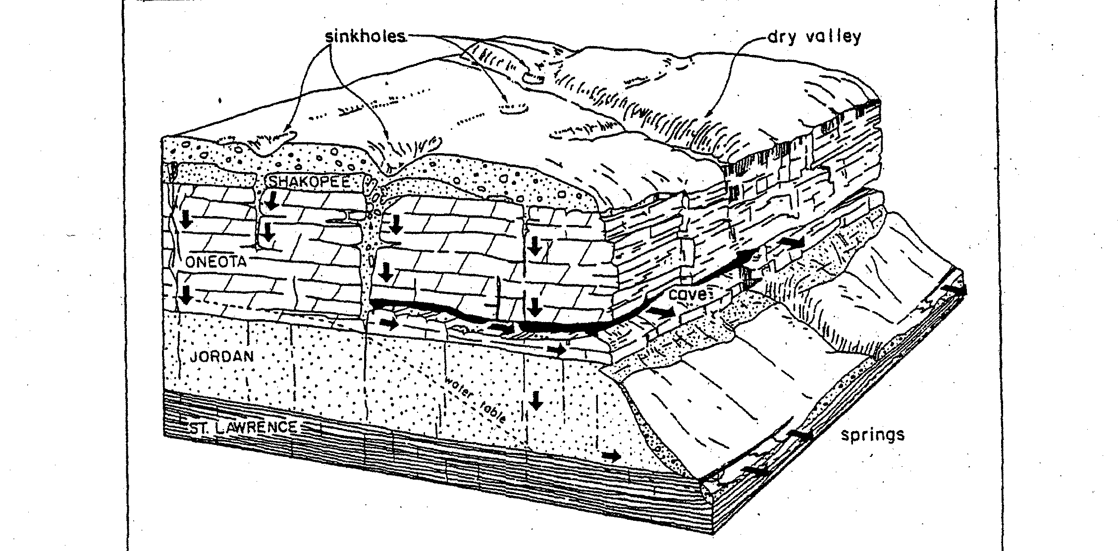
Sections 506. 207
and 506.312
-
These sections regard
the
construction of lagoons and non-lagoons in karst areas. The
Agency
is concerned that ifa single boring is made to a maximum depth of 20 feet below the
waste handling structure bottom elevation,
as
is proposed in these new sections of Part 506, a
void maybe present below the proposed livestock waste handling structure
and
still be
undetected.
Agency research has revealed the following:
Jannick, et al., 1992, reported that of 14 wastewater lagoon sites in southeastern
Minnesota located over karstic bedrock and with 30 meters
or less of overburden soil or till
over the bedrock, 2 had failed in the twentyyears preceding
1992.
An interim guidance
document titled “ConstructingNew Manure Storage Systems in the Karst Region”
(Minnesota Pollution Control Agency, March 2000), reports that 3 of 22 municipal
-
wastewater treatmentponds failed in the karst region of southeast Minnesota between 1974
6
and 1992. The report also
indicates that one manure storage system had manure seepage into
fractured bedrock occurring
so rapidly that the storage system did not ever
need
to be
pumped.
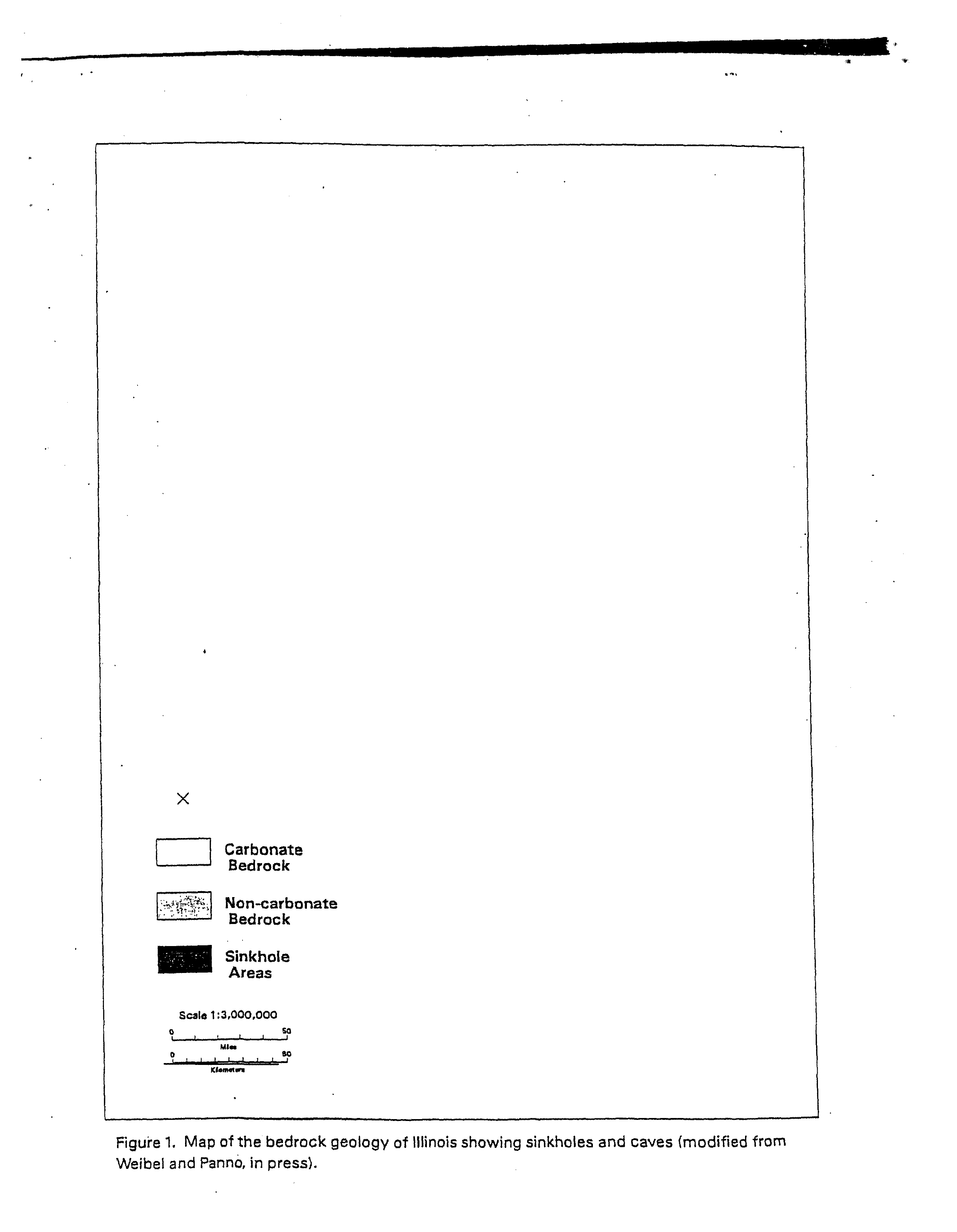
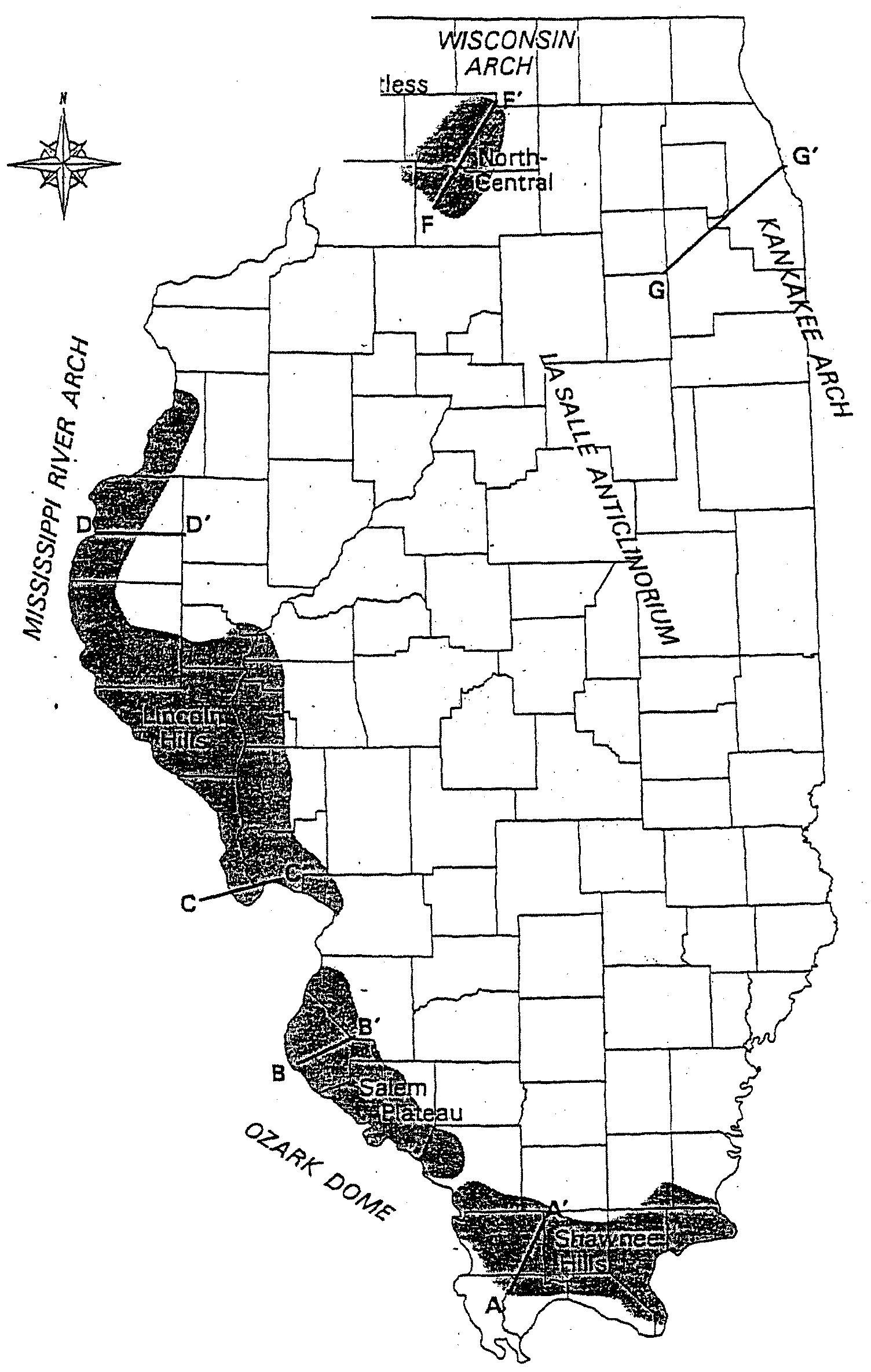
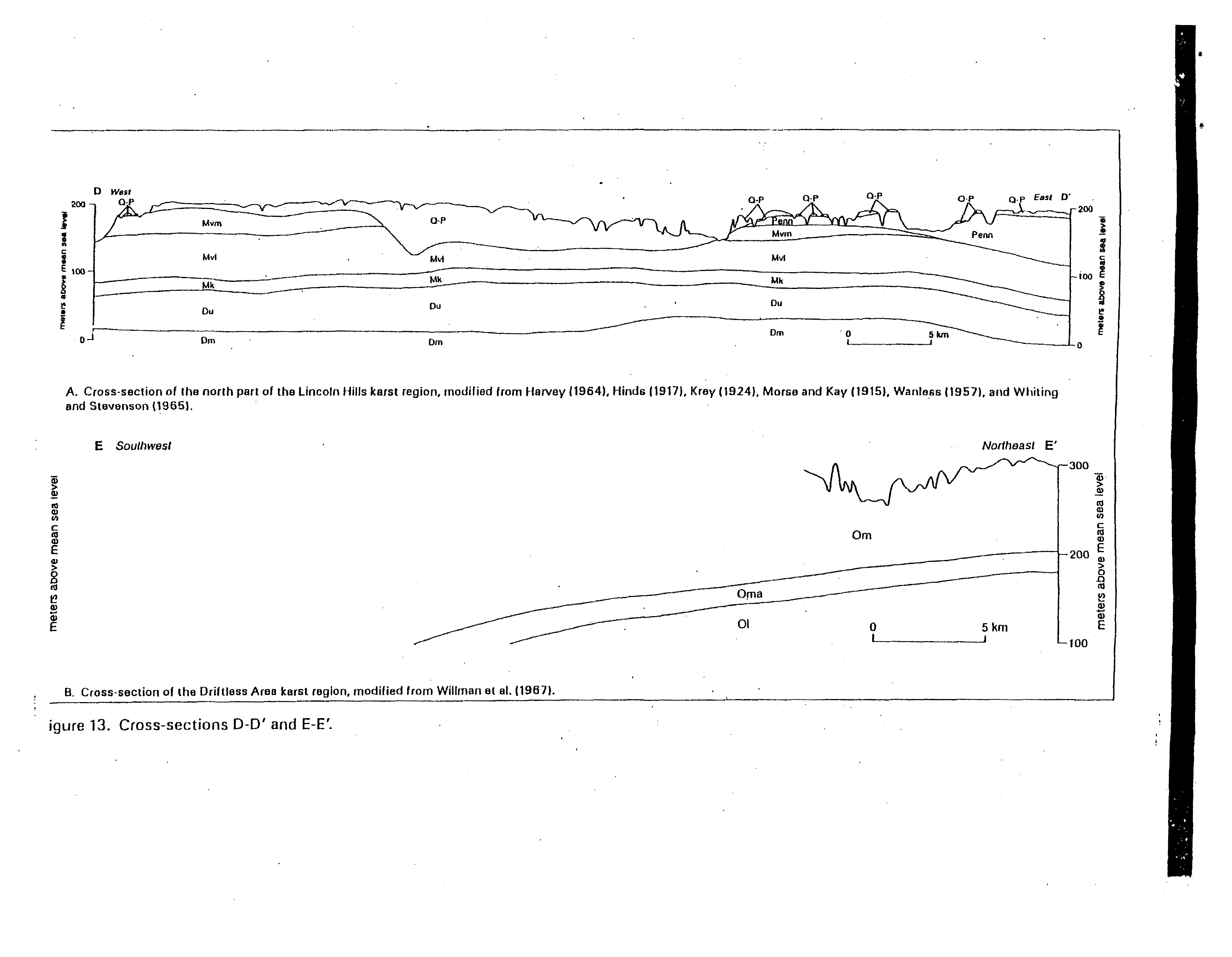
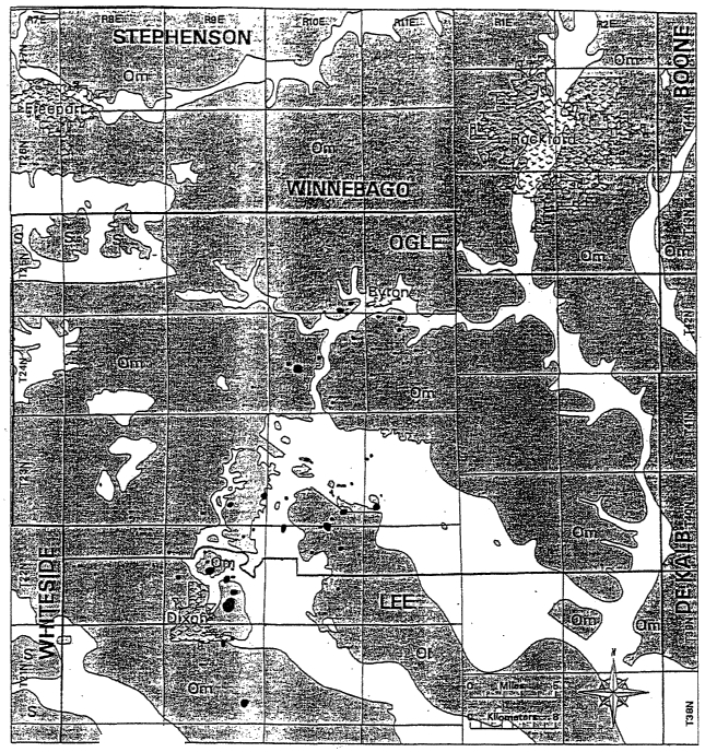
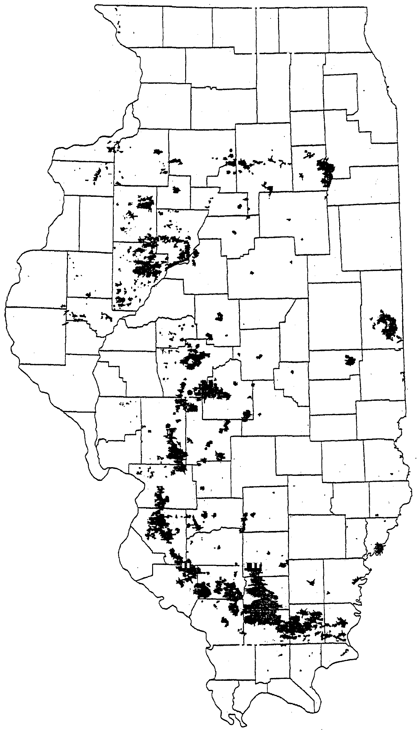
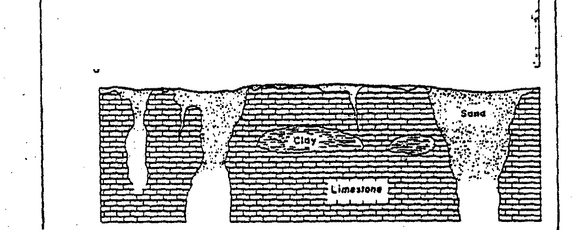
The IDNR- ISGS Illinois Map
8
“Karst Terrains and Carbonate Rocks of Illinois,”
incorporated by reference in Section
506.
104(a)(3), shows that karst areas with sinkholes exist in
areas with drift over the bedrock of 50
feet or
less.
Small areas of the Salem Plateau and Lincoln
Hills karst areas are shown on the map to have sinkholes in areas where drift thickness is greater
than 50 feet over the bedrock.
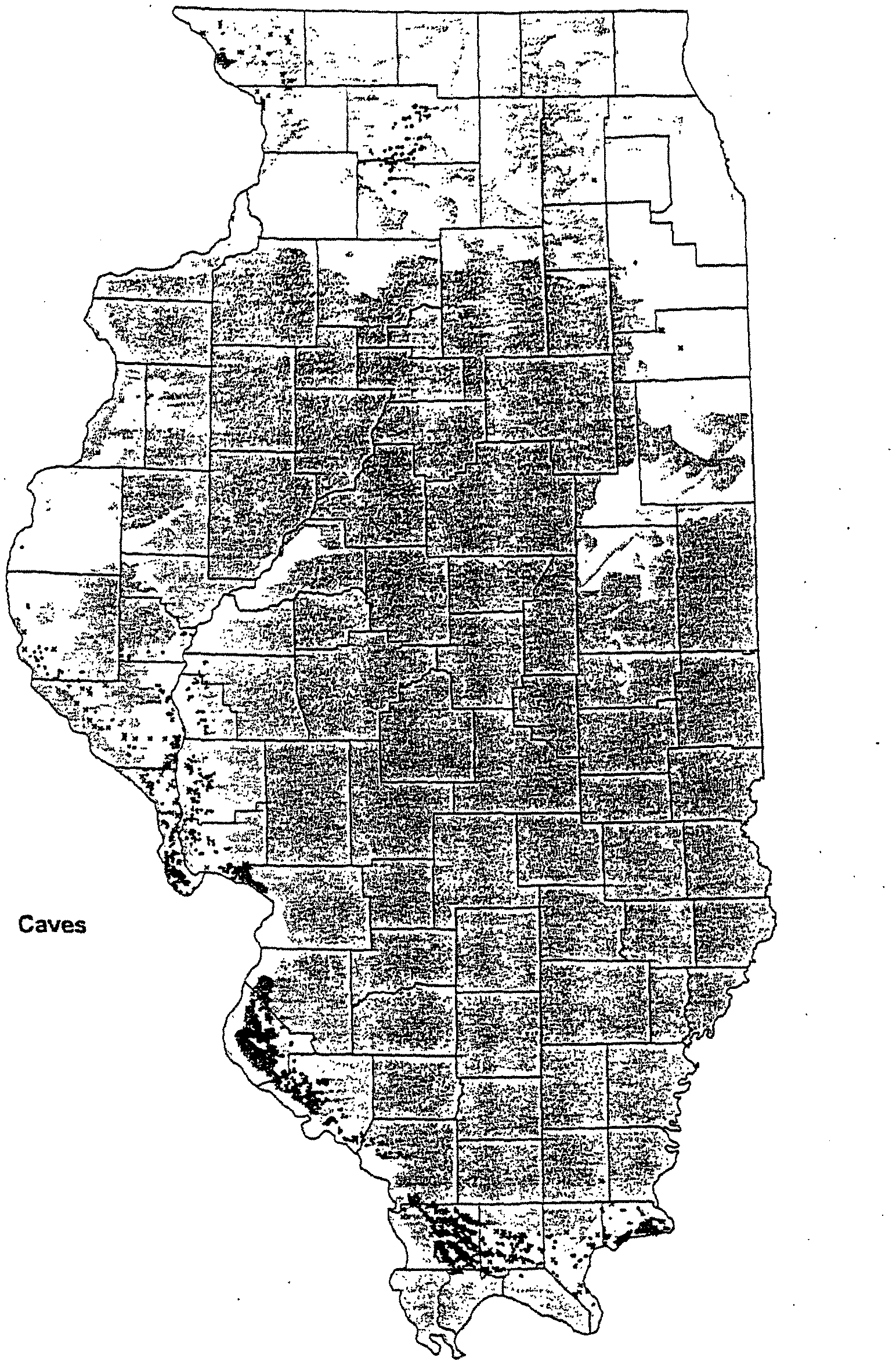
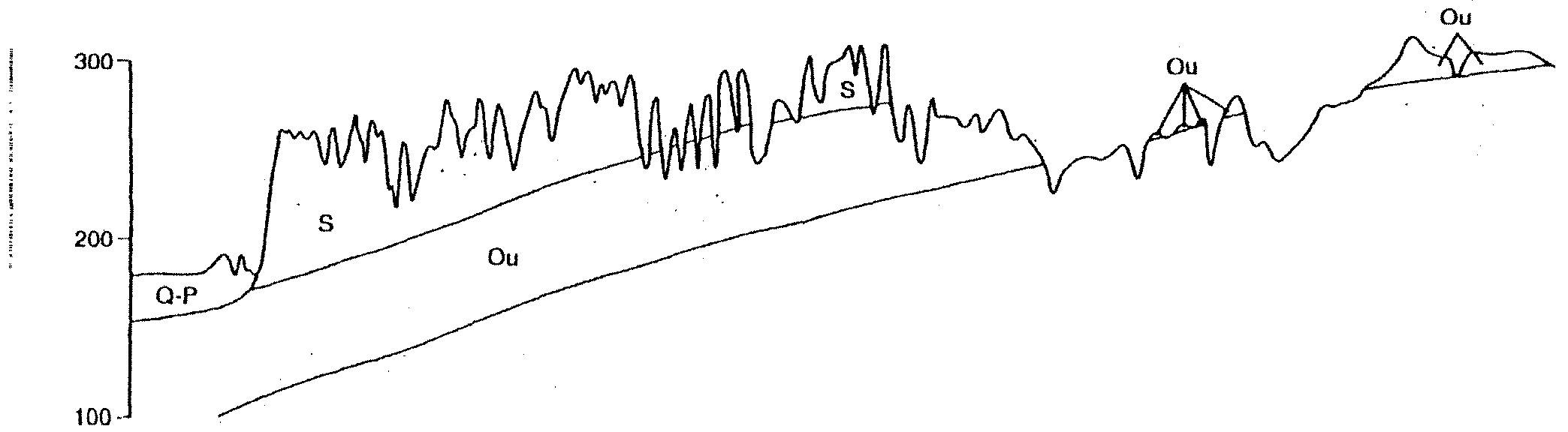
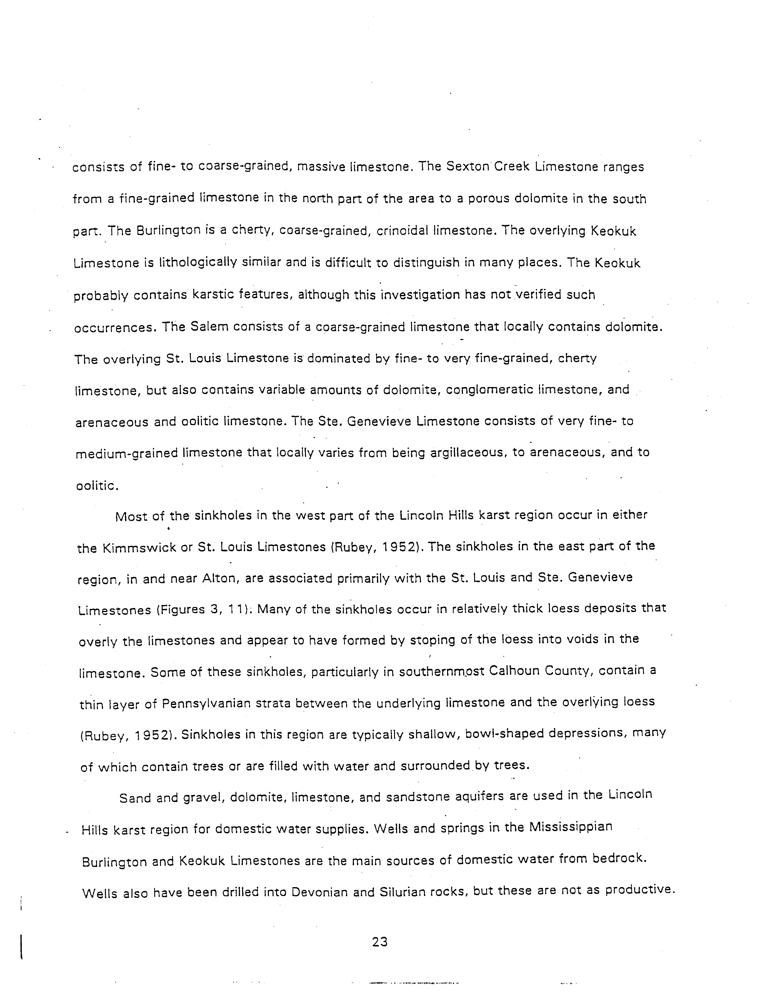
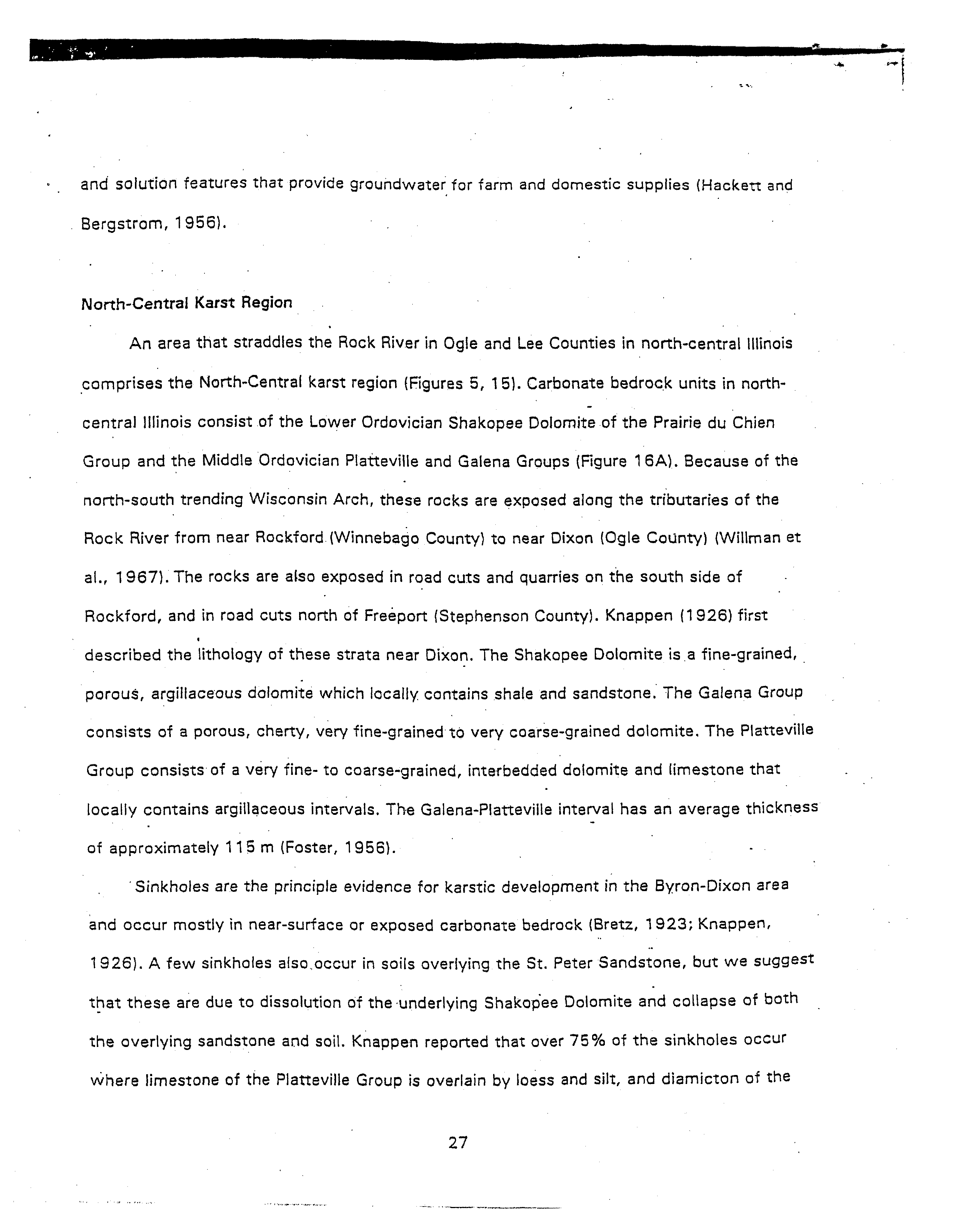
In the report “Karst Regions of Illinois” by Panno, et a! (1997) for
the Salem Plateau karst area,
the bedrock is reported to be typically less than
15
meters (or
approximately 49
feet) belowthe surface, although some areas exceed this depth.
In the Lincoln
Hills karst region the report indicates that many of the sinkholes in this region occur in “relatively
thick bess deposits.”
Most sinkholes form
in driftthickness of less than 20 feet below the
surface in the North Central Karstregion according to the report by Panno. The formation of
sinkholes appears to occur in areas with depth to bedrock up to 50
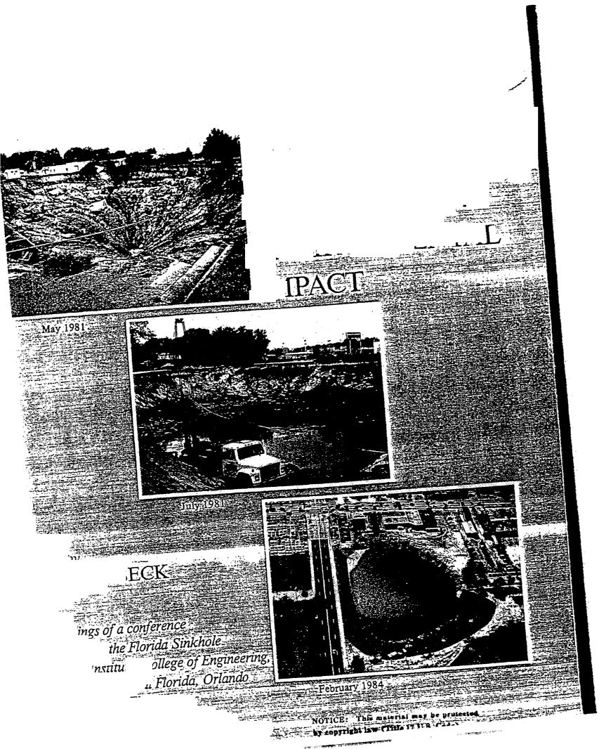
feet or more in Illinois. Benson
and La Fountain,
1984, state that 1000
borings conducted on agrid would be needed for a 90
probability to detect a void of2.3 meters
in size on a one acre site.
-
The
Agency concludes, therefore, that ifa single boring is made to a maximum depth of
20 feet below awaste handling structure bottom elevation a void-may be-present below the
proposed structure and still be undetected.
The
Agency recommends a more comprehensive
investigation based on several sources of data.
Such systems are described below from
-
information on programs in Minnesota and Missouri.
The State ofMinnesota adopted regulations in October,
2000 regarding the location of
manure storage structures in karst areas. The regulations as adopted require that certain facilities:
•
have aminimum separation
from bedrock of twentyto forty feet for earthen liners,
based
on the size of operation
and type
of structures,
•
use rigid structures or
composite
earthen/synthetic liners,
7
•
limit the size of manure storage structuresto 250,000 gallons,
•
prohibit manure storage structures if
the
bedrock is within
5
to
15
feet of the livestock
waste handling structure bottom, or
•
relocate away from the karst features.
Minnesota also convened a workgroup of engineers that were not state regulatory
personnel to determinewhat should
be required for livestock facilities located in karst areas
(Minnesota Pollution Control Agency, 2000, Minnesota
Pollution
Control Agency, 2001).
The
report from that workgroup indicates
the following:
-
•
that in
5
instances earthen manure storage structures have failed due-to- sinkhole
development in states other than Minnesota,
•
Minnesota
and
other states also have had non-livestockwastewater treatmentponds fail
due to sinkhole development,
-
•
In
all cases
the failures have occurred when there is no
liner or the liner is designed to
seep at greater than the Minnesota requirements for earthen soil liners. The seepage rate
-
requirement is
1156th
inch per day. l/56~’
inch per day
is equivalent to a 2 feet thick
liner
with ahydraulic conductivity of
1
x
10~
cm/sec with an operating depth of livestock
waste of 8.6 feet.
-
The Minnesota workgroup issued the
report
“Recommendations of the Technical
-
Workgroup-Liquid Manure Storage Structures in the KarstRegion”
on
December 20, 2000. The
report concludesthat the following be required:
•
no new earthen manure storages located in areas where carbonate bedrock is
less than 5-0
feet from the ground surface and the upper bedrock
is fractured or other geologic strata
where soil collapse or sinkhole formation occurs,
•
construction of manure storage structure is not allowed if voids
are
encountered
in
the
construction of
the
structure
or soil inspection,
8
•
minimum bedrock separation of five feet for concrete tanks, dual lined basins, composite
lined
basins
and
above-ground tanks with concrete floors,
•
a secondary liner with a leachate collection system if bedrock separation is less than
5
feet,
-
-
•
soil inspections during construction,
•
diversion of fresh water away from the perimeter of manure storages,
•
annual liner inspections,
•
monitor manure levels,
and
•
emergency response plans.
The
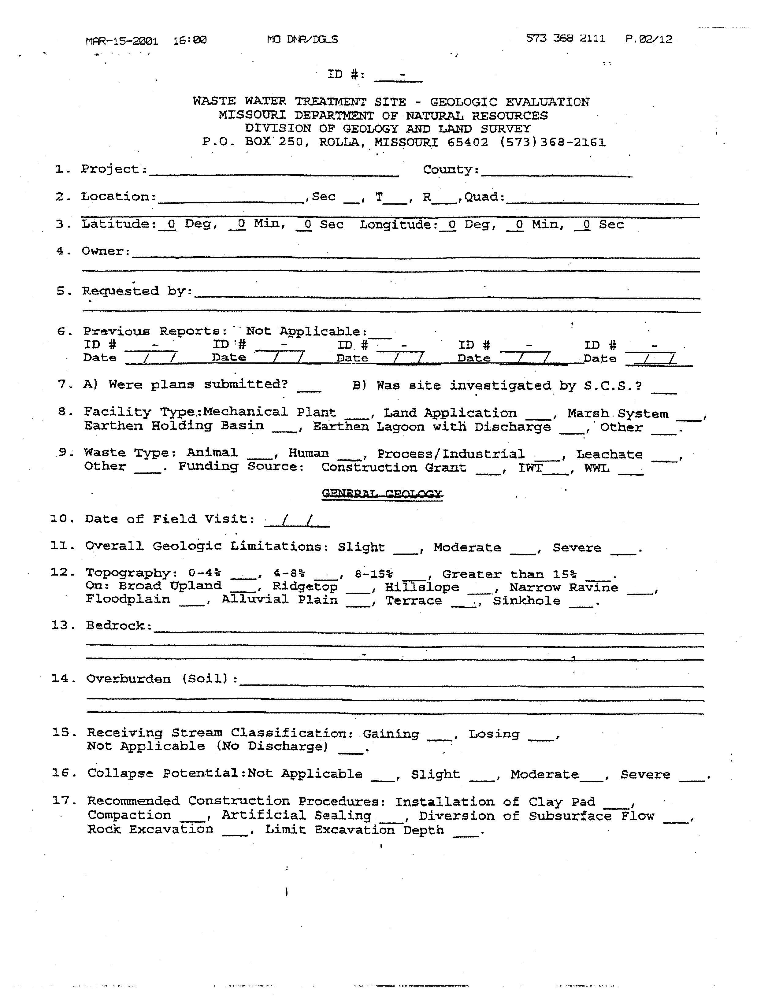
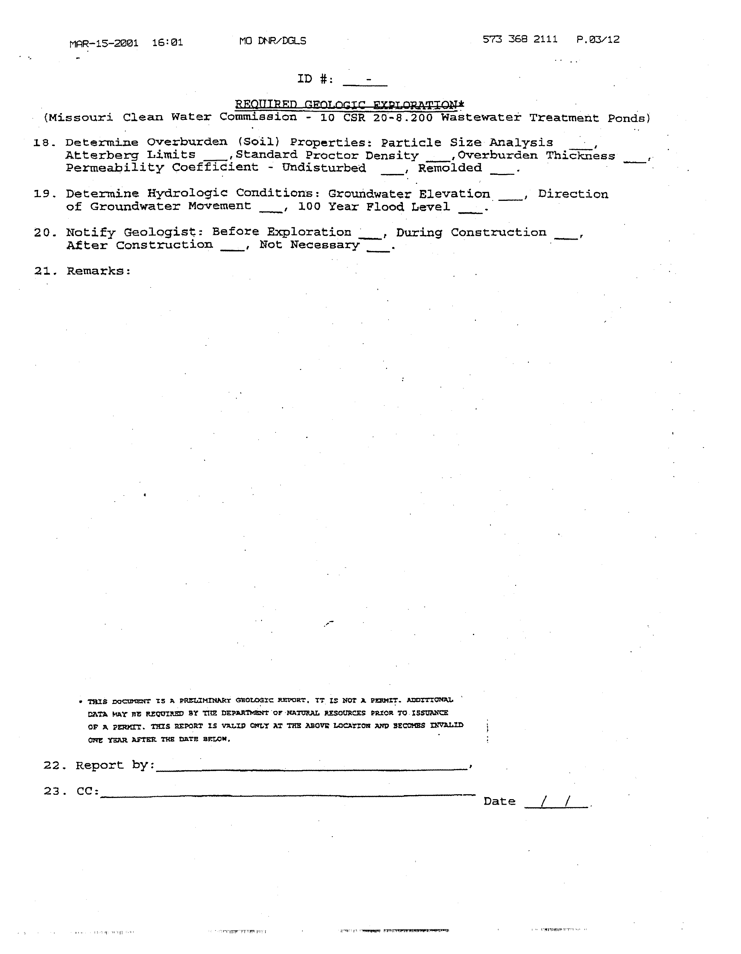
Missouri Department ofNatural Resources regulations~
require that each site for a
earthen wastewater pond, including livestock waste
facilities, be subject to a geological
evaluation. These evaluations are conducted by the Missouri
DepartmentofNatural Resources. If
the facility has severe geological
limitations,the wastewater pond
(i.e., livestock waste lagoon or
holding pond) may be prohibited unless liner technology-and/ormore detailed investigation and
analysis can demonstrate that the proposed pond will not cause groundwater contamination. If the
geological evaluation indicates high collapse
potential, then
the
ponds are generally prohibited
(Missouri Code of State Regulations,
1999).
The Missouri
system provides for the evaluation
and
designation of a score for the
followingeight factors in making an assessment of
the
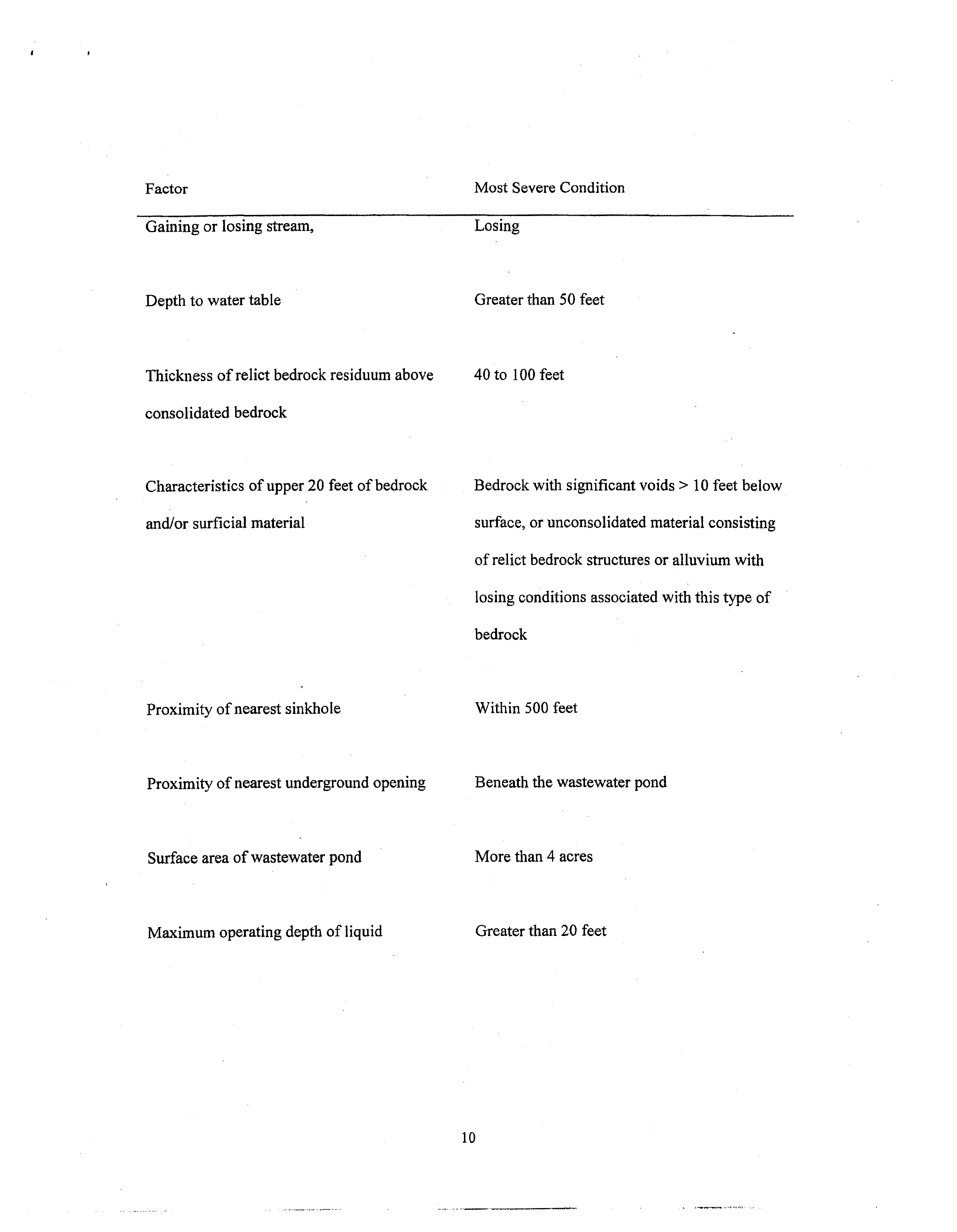
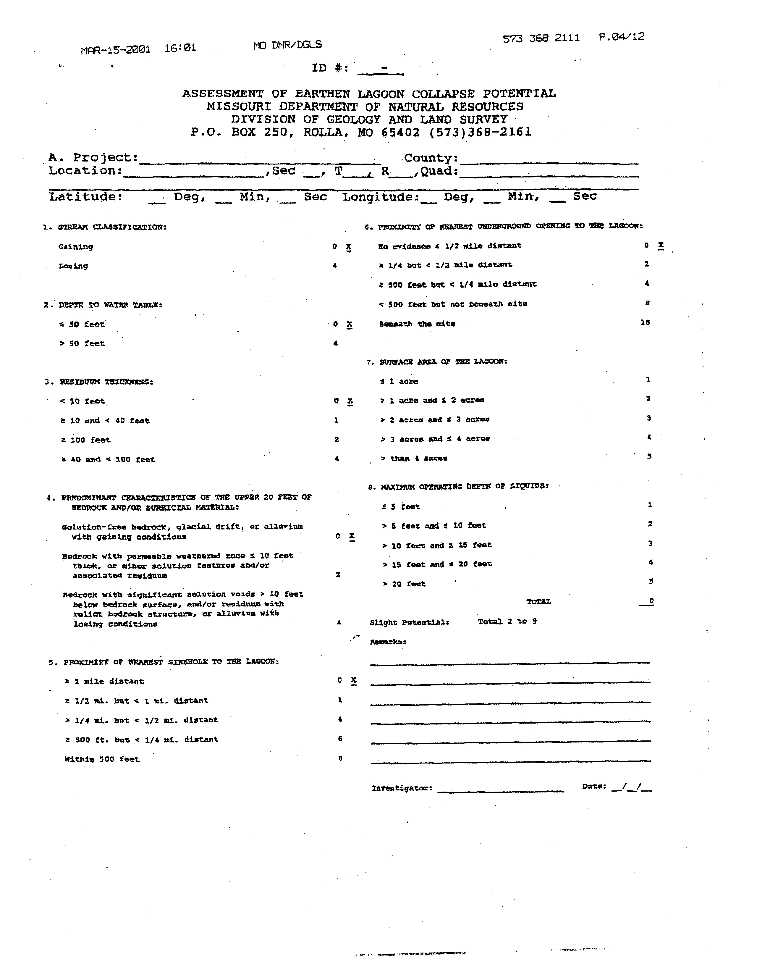
earthen lagoon collapse potential of a site.
A site
is scored if greater than 50
of the top twenty feet ofbedrock is limestone, dolomite
or
calcareous sediments and the wastewater pond bottom is underlain by
less than 20 feet of
unconsolidated material
on top of the bedrock. A site is not scored for an assessment of
earthen
lagooncollapse potential ifthe
earthen
lagoon bottom is underlain by 20 feet or more of
unconsolidated material (other than relict bedrock residuum or alluvium). Listed with each
factor
is the conditionthat is scored the highest for potential wastewater pond
collapse as shown below:
9
Factor
Gaining or losing stream,
Depth to water table
Most Severe Condition
Losing
Greaterthan 50 feet
Thickness
ofrelict bedrock residuum above
consolidated bedrock
Characteristics of upper 20
feet of bedrock
and/or surficial material
Proximity ofnearest sinkhole
Proximity of nearest underground opening
Surface area of wastewater pond
Maximum operating depth of liquid
4Oto
100 feet
Bedrock with significant voids
10 feet below
surface, or unconsolidated material
consisting
of relict bedrock structures or alluvium with
losing conditions associated
with this type of
bedrock
Within 500 feet
Beneath the wastewater pond
Morethan 4 acres
Greater than 20
feet
10
Section
2.5 of the report “Recommendations of the Technical Workgroup- Liquid Manure
Storage in the Karst Region” provides a summary ofthat workgroup’s reviewof requirements of
manure storage structures located in karst areas often states with karst geology. The factors or
restrictions used
by Florida, Pennsylvania, Indiana, Ohio, Missouri, Kentucky, Wisconsin, Iowa
and two other unidentified states surveyed included:
-
•
size-of the manure storage structure,
-
•
use of rigid materials, above ground storage or impermeable liners,
•
liner permeability requirements,
-
•
prohibition of earthen liners,
•
setbacks from sinkholes of 150 to 500 feet,
•
site assessment to determinerelative risk, and
-
•
depth to bedrock
I have attached a chart comparing the Part 506 proposal with the Minnesota and Missouri
regulations and workgroup report.
-
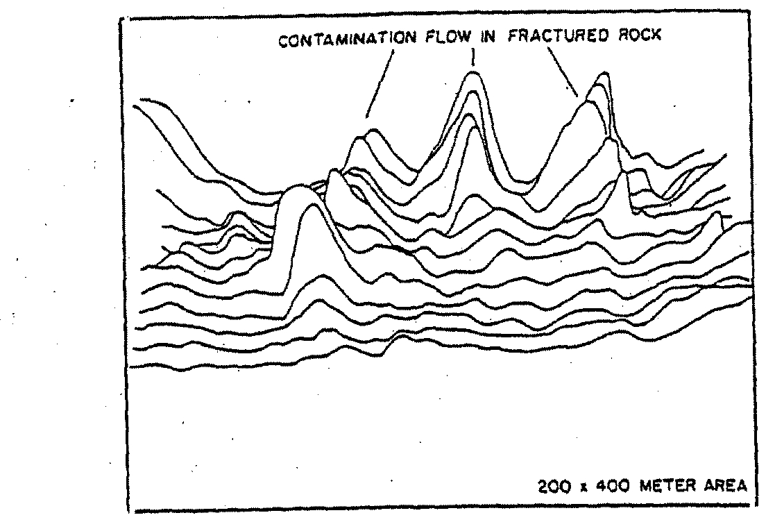
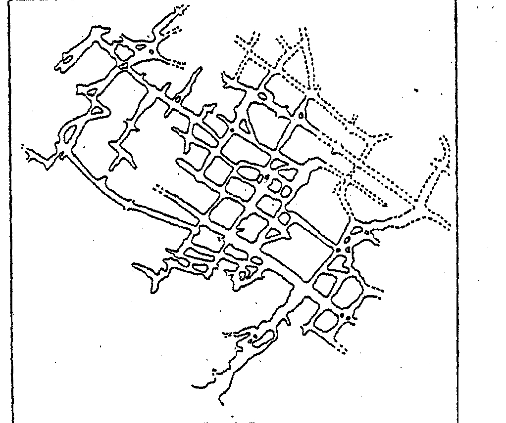
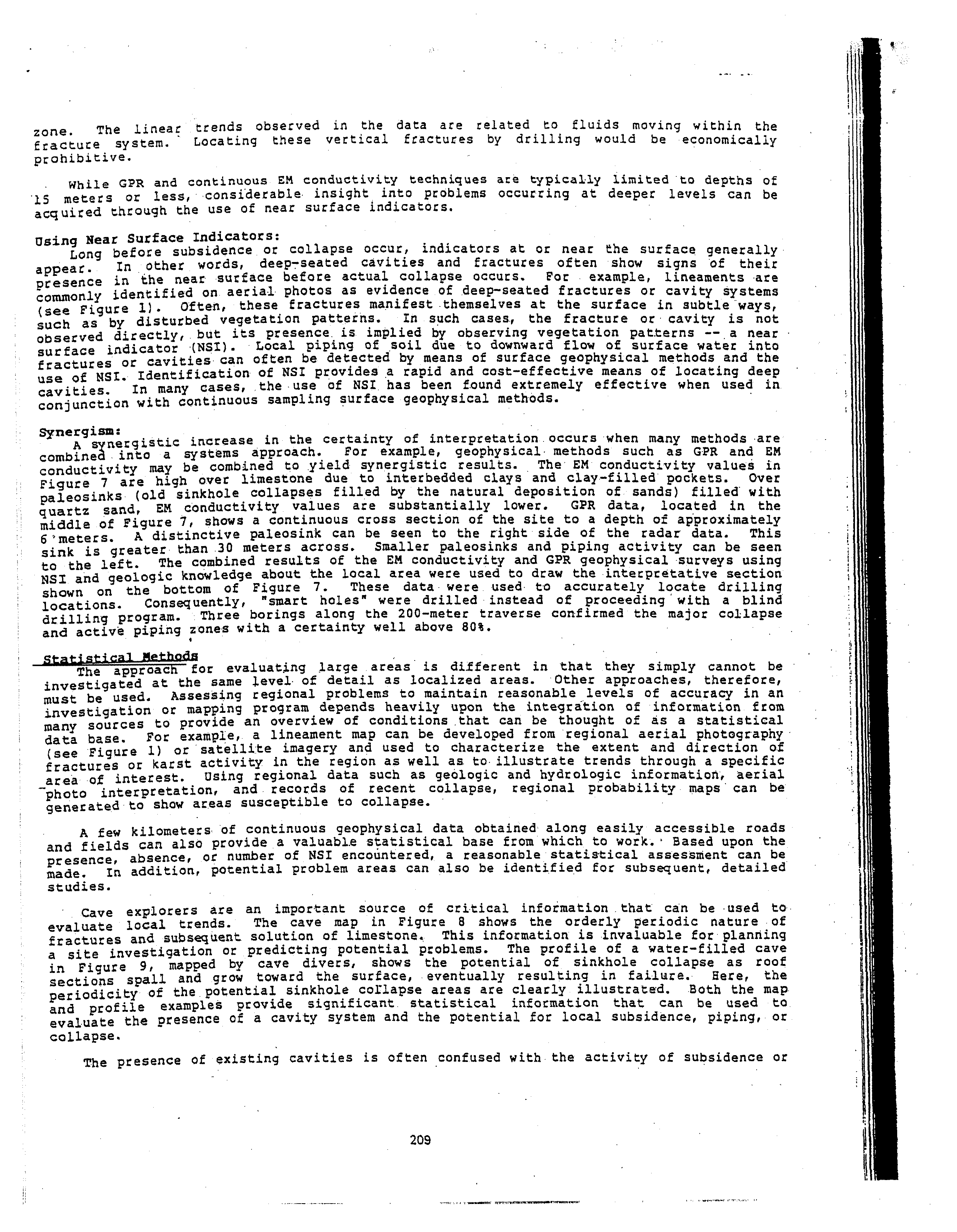
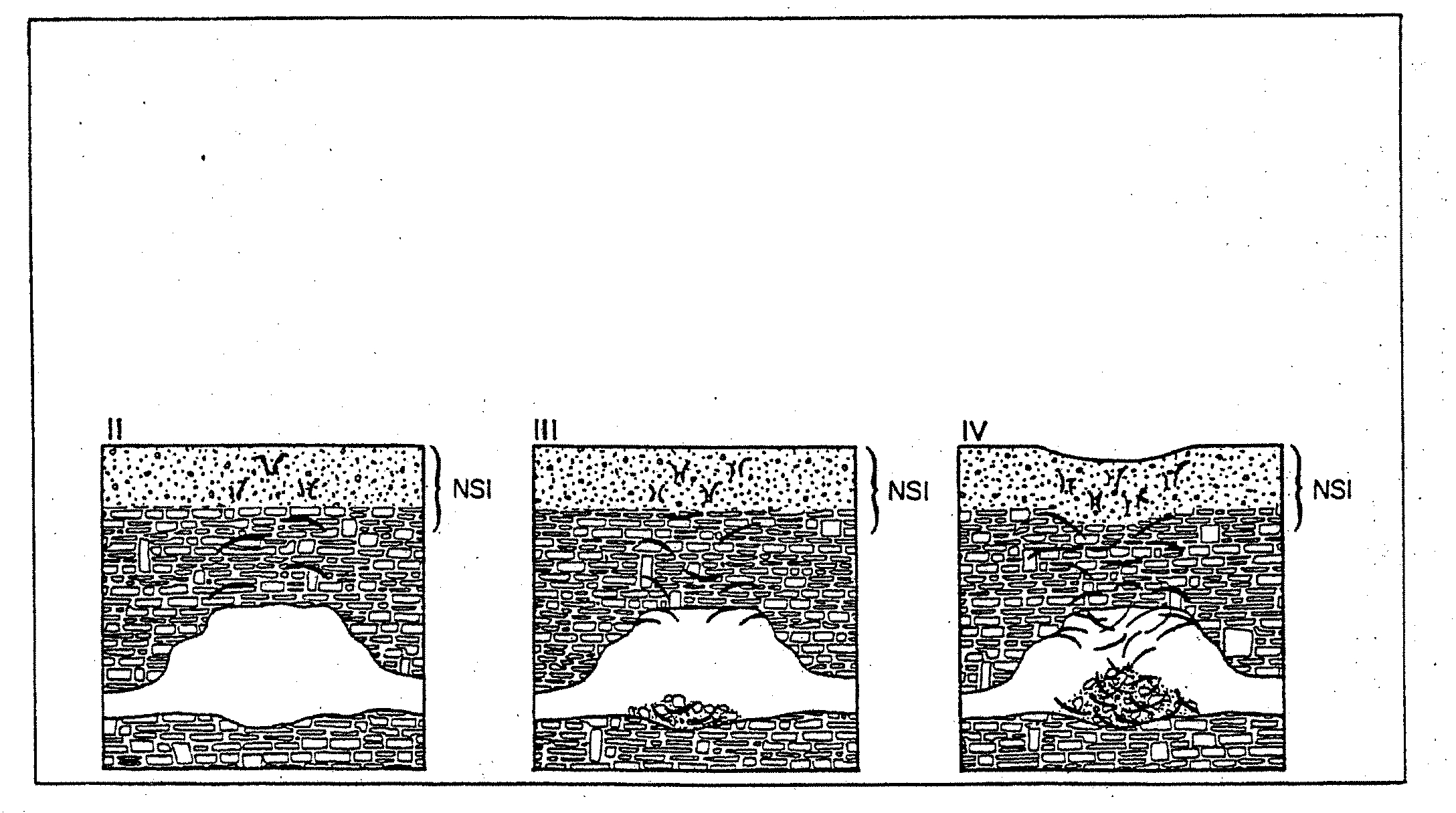
The presence of voids below the structure presents the greatest threat in karst areas to the
integrity of the waste storage structure. Based on the above information regarding
karst, a single
soil boring to a depth of 20 feet will not be sufficient to reliably detect voids located near the
manure storage structure that can cause failureof manure storage structures. Additional borings
would provide more assurancethat voids are not present. Multiple borings should be conducted to
a depth of at least 50 feet or to the bedrock to detect the presence of voids.
Alternatively, ifa single boring to 20 feet or to bedrock
is used
as proposed, additional
requirements would provide methods to prevent groundwater contamination due to failures of
manure storage structures into fractured bedrock. Examples of these additional
requirements are:
preventing the location of manure storage structures or requiring-the -use ofsecondaryliners with
leachate
collection in areas of shallow soils over bedrock, requiring material and liners based
on
11
depth to bedrock, limitations on the
size of manure storage structures, diversion of fresh water
away from manure storage areas, and prohibitions
based
on detection of voids during
construction.
-
I have used the following materials, which will
be offeredas exhibits in thisproceeding:
‘Benson,
R.
C. andLa Fountain, L. J.,
1984.Evaluation of subsidence or collapse potential dueto
subsurface cavities. Proceedings of the First Multidisciplinary Conference on
Sinkholes. Orlando,
Florida
-
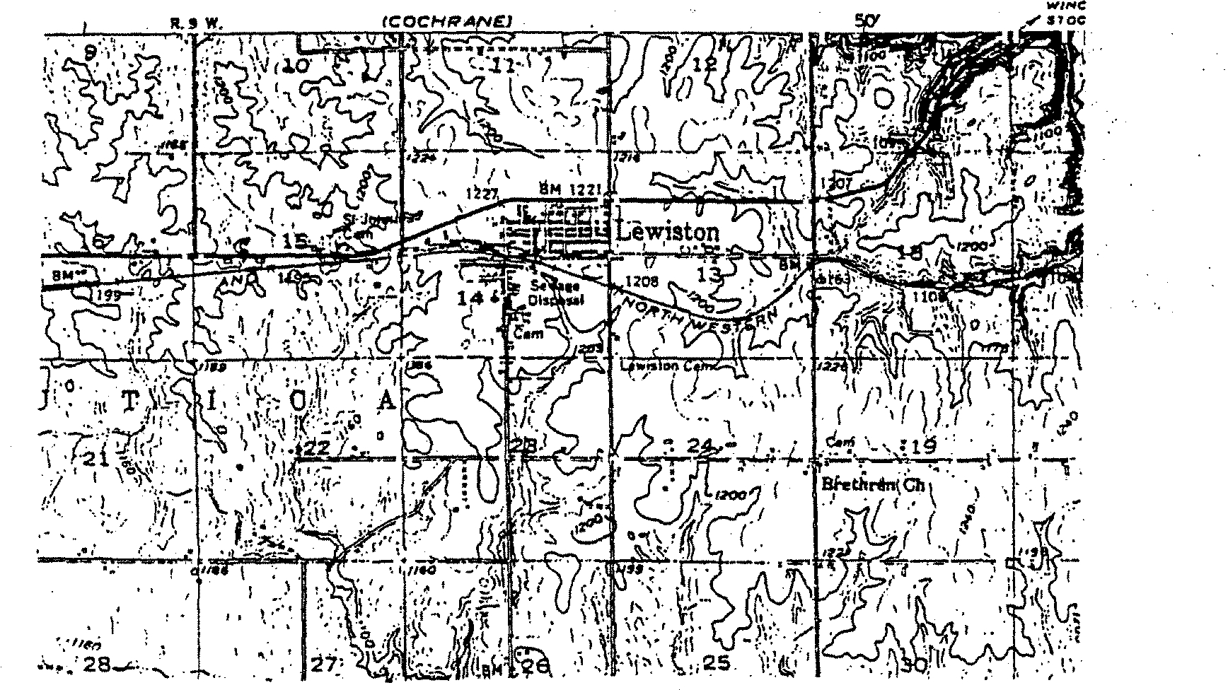
•Jannick, N. 0.
,
Alexander, E. C., and Lanherr, L. J.,
1992.
The
Sinkhole Collapse of the
Lewiston, Minnesota Waste Water Treatment Facility Lagoon. Proceedings of the Third
Conference on
Hydrogeology, Ecology, Monitoring and Management of Ground Water in Karst
Terranes, National Groundwater Management Association.
‘Minnesota Pollution Control Agency, March 20, 2000. Constructing Manure Storage Systems in
the Karst Region. Interim Guidance
Document. Minnesota Pollution Control Agency, Saint Paul,
MN.
•Minnesota Pollution Control Agency, December 20, 2000. Recommendations of the Technical
Workgroup- Liquid Manure Storage in Karst Region To the Minnesota Senate and House
Agriculture and Rural Development Committees. Minnesota Pollution Control Agency, Saint
Paul, MN.
-
‘Minnesota Pollution Control Agency, January
17, 2001. Karst Workgroup Recommendations-
Legislative Fact Sheet. Minnesota Pollution Control Agency, Saint Paul, MN.
‘Missouri Code of State Regulations,
1999. 10
CSR 20-8.200 Division 20-Clean Water
-
Commission, Secretary of State, State of Missouri.
‘Missouri DepartmentofNatural Resources, Division of Geology and Land Survey. Waste Water
Treatment Site
-
Geologic Evaluation. Rolla, Missouri.
12
‘Missouri Department of Natural Resources, Division of Geology and Land Survey. Assessment
of Earthen Lagoon Collapse Potential. Rolla, Missouri.
‘Missouri Department ofNatural Resources, Division of Geology and Land Survey, August
15,
1994.
Guidelines for Assessment of Earthen Lagoon Collapse Potential. Rolla, Missouri.
‘Panno, S. V., Weibel,
C. P. and Li, W.
1997. Karst Regions of Illinois, Open File Series
1997-2.
Illinois Department of Natural Resources-Illinois
State Geological Survey.
•Panno,
S. V.
and Weibel,
C.
P.
1997. Karst Terrains and Carbonate Rocks ofIllinois.
Illinois
Department of Natural Resources-Illinois
State Geological-Survey.
‘State of Minnesota. Minnesota Rules, Chapter 7020.
http://www.revisor.leg.state.mn.us/arule/7020/2100.html
This concludes my testimony, I would be happy to answer any questions that you may
have.
By:
~
/
Daniel
L. Heacock
April 23, 2001
Illinois Environmental Protection Agency
1021
North Grand Avenue East
-
P.O. Box 19276
Springfield,
Illinois 62794-9276
13
F
cqis-Iativg.
FACT~J-S-HEE.T
-
____
Minnesota Pollution
Control
Agency
Karst
Workgroup
recommendations
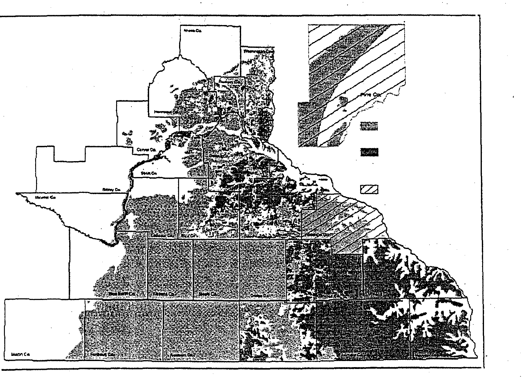
Introduction
-
Due
to its unique karst geology (fractured limestone
bedrock overlaid with shallow soil, often with
sinkholes), much of southeastern Minnesota
represents a sensitive environment for containmation
of ground water and surfacewaters.
One of the
environmental concerns about karst geology is the
potential forsinkholes to form below wastewater- or
manure-storage structures, causing contaminants to be
channeled directly into
the ground water.
Sinkholes
have formed below three poorly lined municipal
wastewater-treatrnent ponds
in Minnesota and at
several poorly lined wastewater and liquid manure
storage areas in other states.
Ground water
contamination problems have also resulted from
chronic seepage of liquid manure into cracks in the
bedrock that are directly connected
to aquifers.
Background
-
Recognizing the environmental sensitivity of the karst
region, the Minnesota Pollution Control Agency
(MPCA) recently incorporated into rule (Chapter
7020) several
standards for construction of liquid
manure-storage systems in areas prone to sinkhole
development.
In response to the rule
changes, the
Legislature requested that a workgroup be convened
to review and propose standards relatedto this topic
according
to the requirements in section
13 of 2000
Session Laws, Chapter435.
-
-
The MPCA convened a workgroup consisting of 10
engineers, none of whom are employed by state
regulatory agencies, in accordance with the guidelines
set forth by the Legislature, which specified that
engineers in the workgroup be from the private sector.
At
the requestof the workgroup, two or more
hydrogeologises
experienced in the karst region were
present at each meeting to advise on issues pertaining
to karst geology,
soils andhydrogeology.
The
workgroup met over eight days between August and
November.
The workgroup did not build from
existing MPCA policy,
but rathertook a fresh look at
standards needed for the karst region.
The
workgroup considered areas “susceptible to soil
collapse
or sinkhole formation,” to include all
land
where the depth to carbonatebedrock is less than 50
-
feet, and the uppermost bedrock
is fractured carbonate
materials or other bedrock where soil collapse
or
sinkhole formation occurs.
karst Workgroup recommendations
Following considerable study oftechnical information
from Minnesota
and other states, the workgroup
developed
several standards forthese areas.
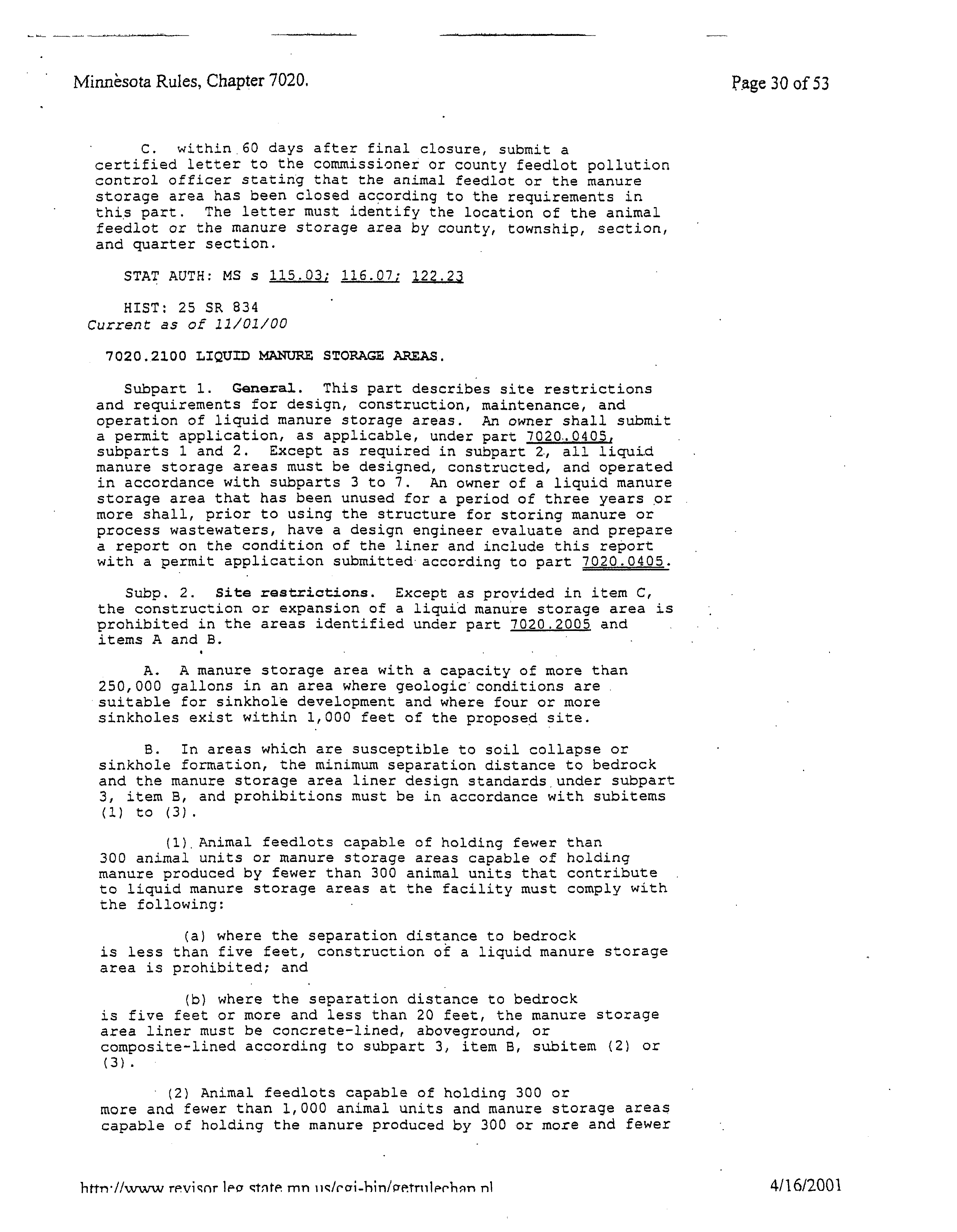
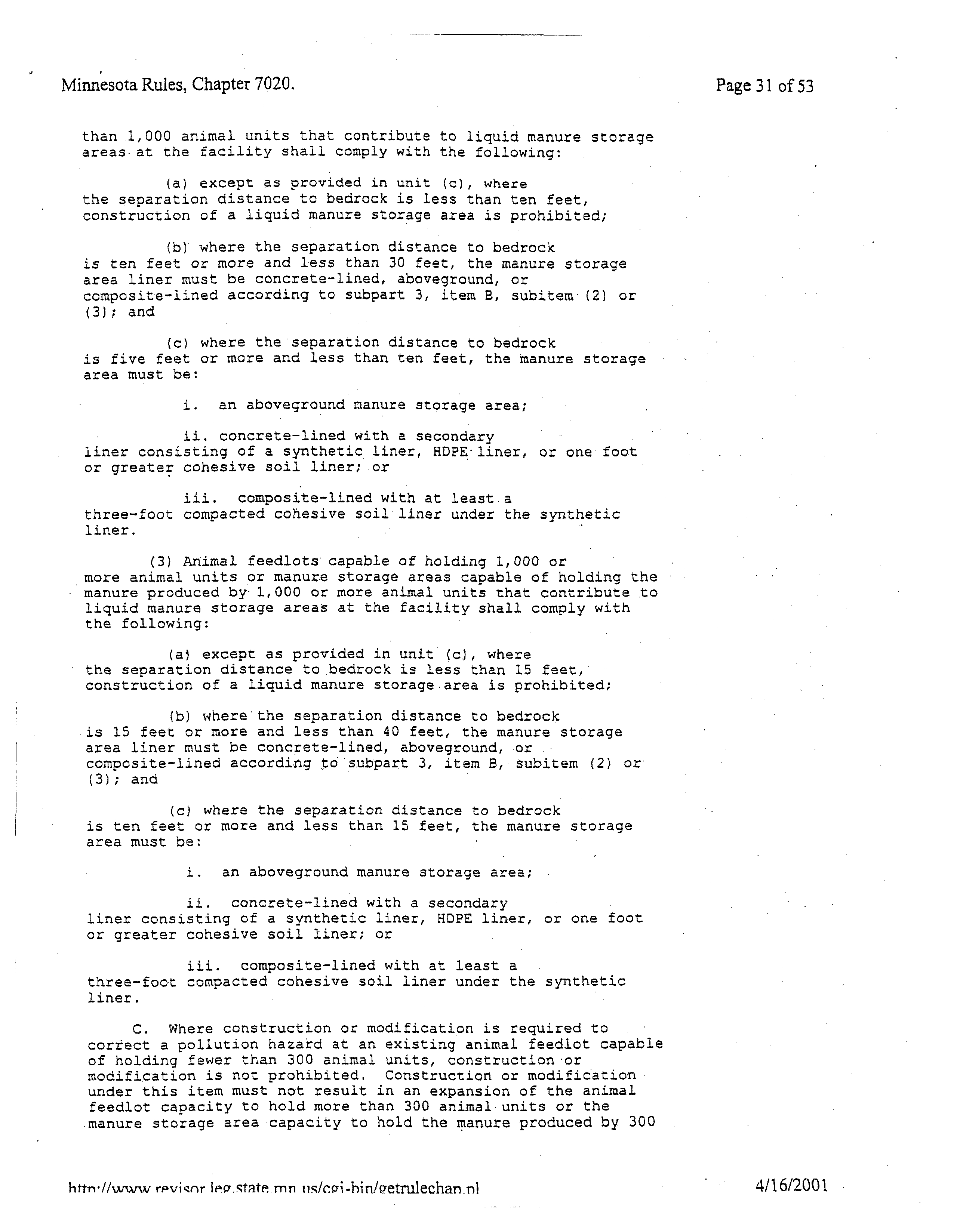
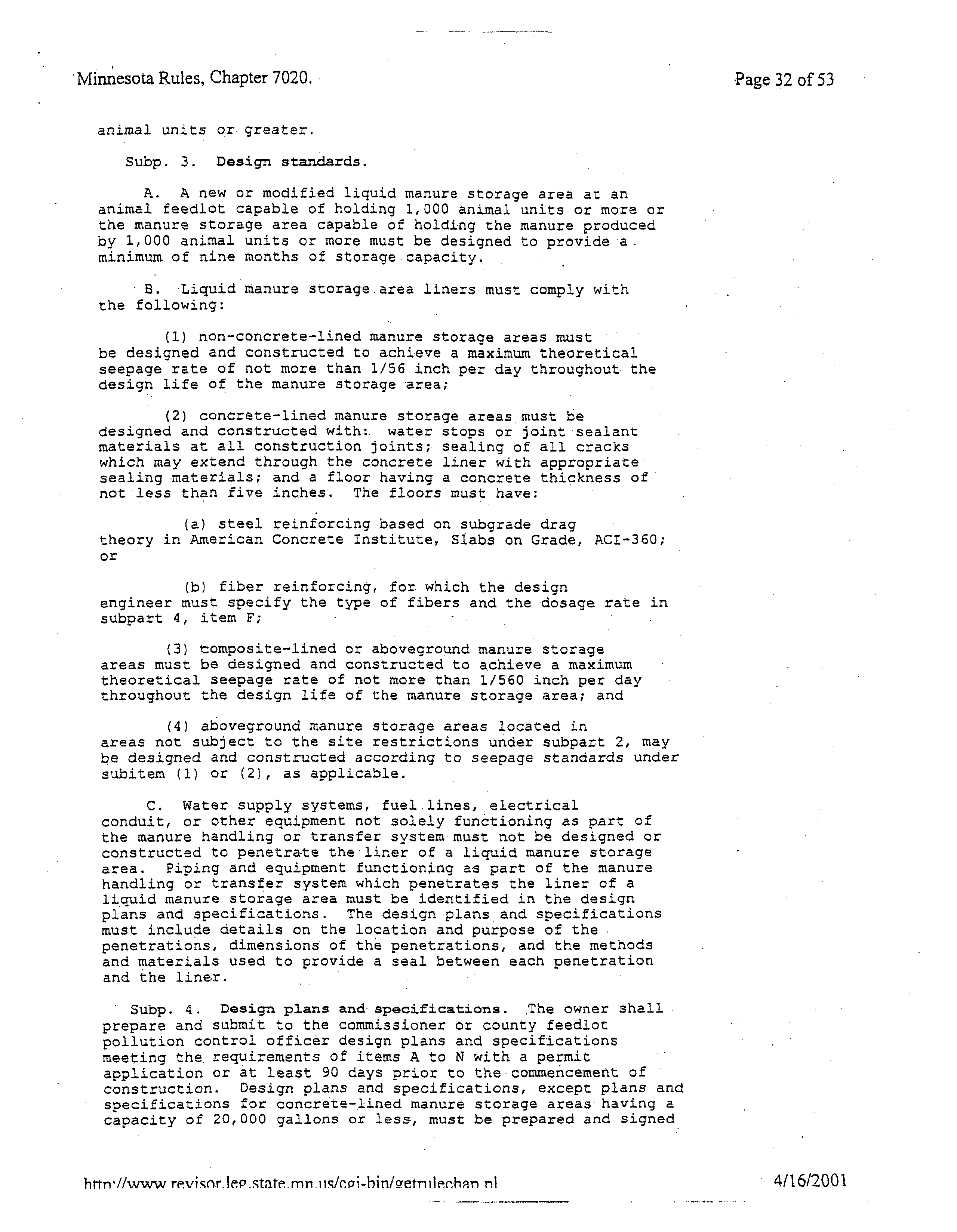
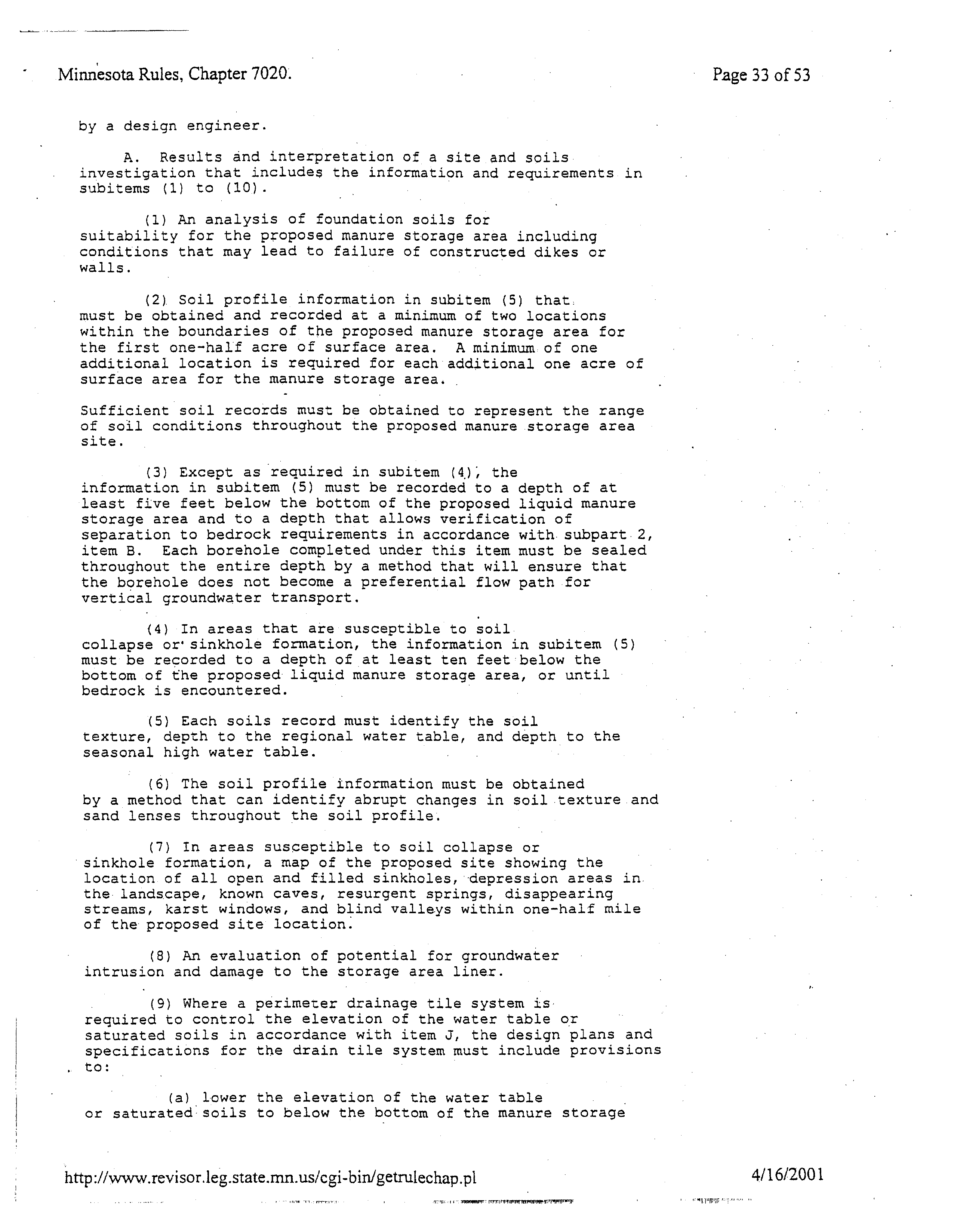
Location restrictions
•
Maintain a 300-foot setback from sinkholes.
•
Relocate site if subsoil inspections during
excavation indicate soil subsidence
or sinkhole
development.
•
Avoid construction over mapped caves that
become
registered with the state.
Design specifications
-
a
Use
dual liners, -concrete liners or above-ground,
-
glass-fused metal tanks.
•
Limit maximum
capacity
ofa single cell to three
million gallons (no total-capacity limit per
farm
and no restrictions based on
animal-unit
numbers).
-
a
Maintain a five-foot minimum separation between
manure and bedrock, with some exceptions.
January17,
2001
Minnesota Pollution
Control Agency,
520 Lafayette
Road
North, Saint Paul, MN
55155-4194
(651) 296-6300,
toll-free (800) 657-3564,
TTY (651)282-5332 or (800) 657-3864
This material
can
be
made
available
in
alternative formats
for people with
disabilities.
®
Printed on recycled
paper containing at least
30
percent fibers from paper
recycled
by consumers.
Minnesota
Pollution
Control Agency
-.
Convey
roof and site runoff waters away from the
manure-storage area.
-
Identifying and responding to failures
•
Monitor manure levels regularly and conduct an
annual inspection of the liner.
•
Develop an emergency response plan.
The
workgroup recommended that the proposed
standards replace existing MPCA rules pertaining to
design standards in areas
susceptible
to sinkhole
formation.
It also suggested that
these
-
recommendations
be reviewed
and refined after
furthersinkhole-formation studies are
completed.
Similarities between recommendations
and existing regulations
-
Many similarities can be found when comparing
current Minn. R.
ch.
7020
and workgroup
recommendations for
areas susceptible to soil collapse
or sinkhole formation.
For example, both the existing
rules and
workgroup recommendations:
•
establish 300-foot setbacks from sinkholes.
•
include major restrictions foruse of cohesive soil
liners alone.
•
allow for use of concrete-lined, dual-lined and
above-ground storage.
•
establish a similar minimum soil thickness needed
above bedrock foruse of concrete, composite and
above-ground
liners at small to moderate-size
feedlots.
-
-
Differences between recommendations
and existing
regulations
•
Current rules forminimum
separation-to-bedrock
restrictions vary from five to
15
feet for concrete
pits, dual-lined basins and above-ground tanks,
depending on the type of liner and the number of
animal units on the farm.
The workgroup
recommends that separation to bedrock be a
-
minimum offive
feet, except fortwo types of
designs
where. separation
to bedrock can
be less
than five
feet.
•
MPCA rules allow cohesive soil liners alone
where there is a substantial soil thickness (e.g.,
20
to 40 feet). between manure and bedrock
The
workgroup recommends that no
cohesive soil
liners be used alone without another liner in areas
with less than 50
feet from ground surface to
-
Page2
carbonate bedrock until further geologic study
identifies the areas with less than 50
feet to
-bedrock that have a low potential for soil collapse
or sinkhole formation.
•
MPCA rules
set a 250,000-gallon limit per storage
cell in areas where there are four or more
sinkholes within
1,000 feet.
No other storage-
capacity limits
are set in rules.
The workgroup
recommends a three-million-gallon limit in all
areas susceptible to sinkhole formation
Recommendations for additions to
existing regulations
Other recommendations that the workgroup made are
consistent with MPCA policy and past permit
-
conditions, but
are not currently established in rule for
all new liquid-manure-storage facilities in sinkhole-
prone
areas.
The workgroup proposes that the
following be added to state rules for areas susceptible
to sinkhole formation:
•
-
inspections of subsoil during construction,
•
diverting freshwater away from the
manure-storage area,
•
annual liner inspections,
•
monitoring of manure levels and
-
•
emergency response plans.
What’s next?
The
MPCA intends to implement workgroup
recommendations in the following ways:
1)
Study technical information from the workgroup
proposals as a basis for future rule
revisions.
2)
Issue permits with the workgroup standards until
the rule
can be revised (where an equivalent level
-
-
-
of environmental protection is achieved).
3)
Modify MPCA guidelines
to reflect workgroup
proposals.
4)
Discuss with other agencies how and when to
implement recommendations for further study.
For more -information
If you have any questions or would like more
information about the Karst Workgroup’s
-
-
recommendations, call David Wall at
(651)
296-8440
or e-mail
him at david.wall@pca.state.mn.us.
Recommendations
of the
Technical Workgroup
Liquid Manure Storage in the Karst Region
To the
Minnesota Senate and House
Agriculture and Rural Development Committees
-
December 20,
2000
Convened by the Minnesota Pollution Control Agency
Printed
on recycled
paper containing at
least 20
fibers from paperrecycled by consumers.
AcknowIed~ements
We extend our sincere thanks to the dedicated technical workgroup members who gave a
considerable amount of time and effort to attend numerous meetings and review materials.
The
Minnesota Pollution Control Agency (MPCA) gratefully acknowledges private sector engineers
that voluntarily contributed -their time and attention through this unfunded directive.
The
workgroup and MPCA gratefullyacknowledge
the public sector staff from the NaturalResources
Conservation Service, University of Minnesota, Minnesota Department of Health, Minnesota
Extension Service, Minnesota Department of Natural Resources, Minnesota Geological
Survey
andIowa Geological Survey who-participated in this endeavor.
The workgroup would like to
express their sincere thanks to those who traveled great distance to supply information and
testimony to the workgroup.
-
Table of
Contents
Chapter
1
-
Introduction
1
1.1
Workgroup Charge and Scope
....
1
1.2
Workgroup Members
1.3
Workgroup process and principles
3
Chapter 2
-
Background
5
2.2
Historical record of failed and successful waste storage systems in karst regions
7
2.3
Benefits of livestock agriculture in the karst region
S
2.4
Minnesota policy on liquid manure storage in karst areas
8
2.5
Other states’ standards for liquid manure storage in karst areas
9
Chapter 3:
Workgroup Recommendations
~.
3.1
Defining areas susceptibleto soilcollapse or sinkhole formation
11
3.2
Recommended standards for areas potentially susceptible to soil coJJ.apse orsinkhole
-
formation
..
3.2.1
Location restrictions
.~.
...
~l-2
3,2.2 Design
Specifications
~
3.2.3
Identifying andresponding to failures
..
14
Chapter 4:
Comparison of workgroup recommendations with
15
current Minnesota policy
4.1 Comparison overview
4.2 Workgroup proposed additions to MPCA rules
17
4.3 Recommended alternative standards to MPCA
rules
~-1
8-
4.3.1
Storage cell capacity limits
~
153-
4.3.2
separation to bedrock requirements
..
4.4 Proposals for further study
~
20
Chapter 5:
Workgroup Considerations and Justification
5.1
Location Restrictions
5.2
Areas with similar water quality risks as the rest of the state
~22
5.3
LinerTypes
~.23
5.4
Separation to bedrock
25
5.5
Feedlot size andstorage capacity
26
5.6
Diverting surface
runoff
~
28
5.7
Construction requirements
~.
2&
5.8
Monitoring
..
29
5.9
Emergency Response Plan
~
29
Chapter 6
-
Recommendations forfurther study
~1l
-
Attachment A
—
Information about Workgroup Members
-
Attachment B
—
Bibliography
-
Attachment C
—
Minnesota Rules
ch.
7020.2005 and
7020.2100
Attachment D
—
ConstructingNew
Manure Storage Systems
in the
Karst Region
Executive Summary
Much of the karst region of southeastern Minnesota represents a sensitive -environment for
contamination of ground water and surface waters, due largely to:
•
shallow soils
above highly fractured bedrock;
-
•
rapid transport of water into and through the subsurface;
-
•
sinkholes and other openings to the fractured bedrock;
•
hydrogeology that is highly variable and difficult to predict; and
-
•
an interconnected system ofsurface water andground water.
One of the environmental concerns in karst regions
is the potential for sinkholes to form below
wastewater- or manure storage structures, causing contaminants to be directly channeled into the
ground water.
Excessive seepage from liquid impoundments
can cause underlying soil to wash
into bedrock fractures, leading to an eventually soil collapse
or sinkhole formation.
Low
-
permeability liners reduce the
likelihood of sinkhole formation below liquid storage areas.
Sinkholes have developed under three poorly lined municipal wastewater treatment ponds in the
karst region, draining several million gallons of wastewater into the ground water below.
In
addition,
several cropland runoffretention ponds establishedfor erosion control have also failed
when sinkholes developed under the ponds.
No
liners of any sort were used for construction of
these runoff retention ponds.
Sinkhole developmentbelow liquid manure storage systems has
-
not been known to occur atthe hundreds of structures in southeastern Minnesota, but has
occurred in at least five instances in other states with karst geology.
Other
karst
states have also
had failures ofwastewater treatment ponds into sinkholes.
All failures in Minnesota and other
-
states have been associated with
earthen
storage ponds having either no liner, or a soil liner
designed to seep more than current Minnesota requirements forcohesive soil liners.
-
-
Ground water contamination problems can also result from chronic seepage of liquid manure
moving into fractured bedrock (without sinkhole
formation).
Well water was severely
-
contaminated at one southeasternMinnesota fa.rmwhen liquidmanure continuously leaked
through a soil liner into
the fractured bedrock immediately below the
earthen basin.
Long-term
-
chronic seepage into fractured bedrock can add bacteria, viruses
and other potential contaminants
to the uppermost bedrock aquifers.
-
Recognizing
the potential for both chronic and catastrophic
failure of liquid manure storage
systems in the karst region, the Minnesota Pollution Control Agency (MPCA or Agency)
established guidelines for construction of liquid manure storage systems in areas susceptible to
soil collapse
or sinkhole formation.
The
agency encourages producers and design engineers to
-
follow these guidelines.
Some ofthe standards in the guidelines were incorporated into MPCA
proposed revisions to Minn. R.
ch. 7020, governing animal feedlots andthe
l1llllfl~E,
lflMlSPOlTllll~R~l
llllLllllillltl
of manure.
Prior to going into effect on October 23, 2000, the revised rule underwent an
-
extensive public review process involving oversight by an Administrative Law Judge.
The
MPCA made several changes
to the rules in response to comments from the
public and the
Judge.
In addition, the Minnesota Legislature reviewed the proposed rules and passed legislation
requiring changes
to several parts ofthe proposed rules (2000 Session Laws, Chapter
435).
No
changes were made by the MPCA or the Legislature to proposed rules pertaining to manure
storage in areas susceptible to sinkhole formation.
However, the Legislature requested that a
workgroup be conyened to review and propose standards related to this topic.
The legislation in
section
13
of2000
Session Laws,
Chapter
435,
states:
“The commissioner of the Pollution Control Agency shall convene a workgroup consisting of
representatives
from Natural Resources Conservation Services andprivate sector licensed
professional engineers, including individuals with expertise in hydraulics, structural systems,
and geology, to review and propose design standards for liquid manure storage facilities in
areas susceptible to soil collapse and sinkhole formation.
This review shall include an
evaluation ofwhether such standards should be volume based or animal unit based.”
The MPCA responded
to the legislationby convening a workgroup consisting often engineers
with collective backgrounds in structural engineering; hydraulics; geology; design and
-
construction ofliquid manure storage systems in the karst region; assessing seepage through
manure storage system liners; geotechnical evaluation; alternative liners for liquid containment;
and liner reinforcement.
All workgroup recommendations were made by the ten engineers
forming the workgroup, none of whom are employed by
state regulatory agencies.
At the
request of the workgroup,
two or more hydrogeologists experienced in the karst region were
present at each meeting to advise on
issues pertaining to karst geology,
soils and hydrogeology.
The workgroup was specifically asked by the legislature to target standards for liquidmanure
storage in areas “susceptible to soil collapse or sinkhole formation.”
The workgroup
considered
areas “susceptible to soil collapse or sinkhole formation,”
tO include all land where the depth to
-
carbonate bedrock is less than 50
feet, and the uppermost bedrock is fractured carbonate
materials
or other geologic strata where soil collapse
or sinkhole formation occurs.
In areas not
susceptible to soil collapse or sinkhole formation, the workgroup recommends that the same rules
should apply for liquid manure storage design, construction and operation as throughout the rest
of the state.
-
-
A shortcoming noted by the workgroup with existing information is the
lack of geostatistical
analyses indicating the likelihood of soil collapse to occur in a given area.
The Minnesota
Geological Survey, University ofMinnesota andDepartment ofNatural Resources are currently
examining the relationship between the presence of karst features and associated geologic
conditions.
The recommended measures in this report are intended to serve
as interim standards
until the studyis completed and the standards can be revised to more specifically reflect a
geostatistical evaluation of sinkhole formation.
-
The workgroup did not build from existing MPCA policy, but rather took a fresh look atneeded
-
standards for the karst region.
ExistingMPCA policy was only briefly considered during the
workgroup process.
Workgroup recommendations made in this report reflect
the best
professionaljudgement of the workgroup members made after considerable study and discussion
of available information on this topic.
11
The workgroup recommends the followingprotective measures for areas susceptible
to soil
collapse
or sinkhole
formation.
These measures are meant to be used in addition to the existing
protective measures required by the MPCA throughout the state.
These standards pertain to
1)
location restrictions, 2) design, and 3) identifying andresponding to failures.
The standards can
be summarized as follows:
Location restrictions
-
-
•
Maintain a 300-foot setback from sinkholes;
-
•
Relocate site if subsoil inspections during excavation indicate soil subsidence or sinkhole
development;
-
-
•
Avoid construction over mapped caves that become registered with the State;
-
-
-
Design spec~flcations
•
Use dual-liners, concrete liners or above ground glass-fused metal
-
•
-
Limit maximum capacity of a single cell to three million gallons (no total capacity limit per
farm and no restrictions based on animal unit numbers);
-
-
•
Maintain a five-foot minimum separation between manure and bedrock, with some
exceptions;
•
Convey roof and site runoff waters away from the storage area;
Identifying and responding to failures
-
-
-
-
-.
Monitor manure levels regularly and conductan annual inspection of the liner; and
•
Develop an emergency response plan.
-
-
The workgroup recommends that the proposed standards in this report replace existing MPCA
rules pertaining to design standards in areas susceptible to -sinkhole formation.
They also suggest
that these recommendations be reviewed and relmed after completing further study of the
likelihood of sinkhole formation under various geologic conditions.
Many similarities can be foundwhen comparing Minn.
R.
ch.
7020 and workgroup
recommendations for areas susceptible to soil collapse
or sinkhole formation.
For example, both
the rules and the workgroup recommendations:
-
•
establish setbacks from sinkholes of 300 feet;
-
•
include
mnajor restrictions on use of cohesive soil liners alone;
-
•
allow for use of concrete lined, dual-lined and above ground storage; and
•
establish a similar minimum soil thickness needed above bedrock foruse of concrete,
composite and above ground liners at small to moderate-sized feedlots;
Yet, the specific criteria for some of the recommendations
are different.
Current MPCA rules for
separation
to bedrock restrictions vary from five
to fifteen feet for concrete pits, dual-lined basins
and above ground tanks,
depending on the type of liner and the numberof animal units on the
farm.
Whereas, the workgroup recotumends that separation to bedrock be a minimum of five-
feet, except for two types of designs where separation to bedrock can
be less than five feet.
MPCA rules allow cohesive soil liners alone where there is a substantial
soil thickness between
111
~_~:—
~
-
*
~
manure and bedrock (e.g., 20
to 40 feet).
The workgroup recommends no cohesive soil liners to
be used alone without another liner
in areas with less than-50 feet from ground surface to
carbonate bedrock until further geologic study identifies the areas with less than 50 feet to
bedrock that have a low potential for soil collapse
or sinkhole formation.
-
Other workgroup recommendations, such
as inspections of subsoil during construction and
diverting freshwater away from the manure storage area,
are not stated in MPCA rules but are
consistent with MPCA guidelines.
The MPCA requires manure storage system designs
to
include plans forperiodic
inspection of the liner.
This is consistent with, but not as specific
as
workgroup recommendations
to require regular monitoring of manure
levels and annual liner
-
inspections.
The workgroup recommended emergency response plan requirements for all new
liquid manure storage systems constructed in areas susceptible to sinkhole formation.
Emergency response plans are currently required by MPCA rules at feedlots with 1000 or more
animalunits.
Another difference between current MPCA policy and workgroup recommendations
relates to
storage capacity limits.
MPCA rules set a250,000 gallon limit per storage cell in areas with four
or more sinkholes within
1000 feet.
No other storage capacity limits
are set in rules; however,
recommended guidelines suggest limits that vary with the
liner type and geologic conditions.
The workgroup recommends a three million gallon limit in all areas susceptible to sinkhole
formation, regardless ofproximity of karst features
(with the exception ofthe 300 foot setback
requirement from sinkholes).
The workgroup emphasized that further work is needed
to:
•
Determine the geostatistical probabilities
of soil collapse in different types of geologic
settings;
-
-
•
Study pathogen transport through soils below liquidmanure storage systems in the karst
region;
•
Develop generic emergency response plans that can then be tailored for specific feedlot
operations;
-
•
Conduct research and demonstration projects on alternative manure management approaches
-
that do not rely on liquid storage;
-
-
•
Conduct regular monitoring and inspections of existing liquid manure storage systems; and
•
Collect, manage, analyze, interpret and map geologic and hydrogeologic information needed
-
for engineers designing liquid storage basins in karst areas.
iv
Chapter
1
*
Introduction
ii
Work~rounChar2e
and
Scone
In December
1999, the Minnesota Pollution Control Agency (MPCA) proposed revisions to rules
(Minn.
R.
ch. 7020) governing animal feedlots and the
S!UU(E, 1RfiISP~MflflUII~ilII
~II1IlliTI~
of manure.
The
rule
revision updated the 20-year old rules and modified the approach to permitting feedlots.
The rule
revision also added technical standards for such activities as land application of manure, manure
transportation, open lot discharges, manure storage closure, stockpiling, and construction of
-
liquid storage systems.
Several new requirements specificallyaddressed construction of liquid
manure storage systems in areas susceptible to sinkhole formation.
Prior to going into effect
on October 23, 2000, the revised rule underwent an extensive public
review process involving oversight by an Administrative Law Judge.
The MPCA made several
changes
to the rules in response to comments
from the public and the Judge.
In addition, the
Minnesota State Legislature reviewed the rules and passed legislation requiring further changes
to the proposed feedlot rules (2000 Session Laws, Chapter
435).
No changes were made to the
rules pertaining to manure storage in areas susceptible to sinkhole formation.
However,
the
legislature requested that a workgroup be convened to review and propose standards related to
this topic.
The legislation in section
13
of2000
Session Laws, Chapter 435, states:
“The commissioner of the Pollution Control Agency shall convene a workgroup consisting of
representatives from Natural-Resources Conservation Services and private sector licensed
professional engineers, including individuals with expertise in hydraulics, structural systems,
and geology, to review and propose design standards for liquid manure storage facilities in
areas susceptible to soil collapse and sinkhole formation.
This review shall include an
evaluation of whether such standards should be volume
based or animal unit based.
The
commissioner shall submit the fmdings and recommendations
ofthe workgroup
to -the Senate
and House Agriculture and Rural Development Committees by October 31, 2000.”
In response, the MPCA convened a technical workgroup to address the specific issues required in
the legislation.
The workgroup focused
on standards forwater quality protection thatare directly
related to the design and construction of liquid manure storage systems
in areas susceptible to
soil collapse or sinkhole formation.
Several issues were considered to be beyond the scope of the
workgroup, including in-depth analysis about economics and affordability, extensive
investigation of current water quality throughout southeastern Minnesota, and the socio-political
ramifications of implementing these recommendations
as state law.
Risks associated with
manure application to fields, liquid manure spills and air emissions were also considered to be
beyond the scope and charge of the workgroup (yet these issues are linked to manure storage
techniques).
This document discusses workgroup recommendations made for new liquidmanure storage areas
andmaj or modifications made to existing structures. The workgroup did not address standards
for existing liquid manure storage systems currently operating in the karst region.
1
The MPCA requested and was
granted an extension of the report deadline from October 31,
2000, to January 4, 2001.
1.2
Workgroup Members
-
The MPCA convened a workgroup consisting of individuals who collectively, met the
requirements of the legislation.
The group
includes engineers with expertise in the areas of
structural engineering, hydraulics, and geology.
In addition, engineers were
selected who have
-
experience in the following areas: a) designing and constructing liquid manure storage systems in
the karst region, b) studying seepagethrough manurestorage system liners, c) evaluating
geotechnical information,
and d) using alternative liners and liner reinforcement for liquid
containnient systems.
-
The
ten engineers in the workgroup are listed below.
Their education, experience,
expertise,
-
addresses and phone/e-mail
is includedin Attachment A.
Dr. Randal Barnes, P.R.
-
University of Mintiesota, Department of Civil Engineering
Dr. Chuck Clanton, P.R., P.S.S. (alternate Dr. Kevin Janni, P.R.)
-
University of Minnesota,
Department of Biosystems and Agricultural Engiiieering
Mr. Pete Fryer, P.E.
-
Joint Powers Board, working in association with NRCS
and SWCDs
Mr. Stephan Gale, P.E.
-
Gale-Tech Engineering
-
-
Mr. Art Kaimnes, P.R.
*
Polaris Group
Mr. Robert Mensch, P,.E.
-
Mensch Engineering
-
Mr. Larry Roehi, P.E.
-
WHKS & Co.
-
Mr. Rob-Romocki, P.R.
-
Natural Resources Conservation Service
Mr. Scott Swanberg, P.R.
-
Natural Resources Conservation Service
Mr. Colby Verdegan, P.R.
-
Chosen Valley Testing
-
The MPCA understood the intent of the legislation was for the recommendations to be made
by
the people
from organizations specified in the legislation. All workgroup recommendations
included in this report were made by the ten workgroup engineers.
The recommendations
in this
report were not made by— the state
agency regulatory staff participating in this process.
This is
very different from a rule-making process where state agencies, local government, private
organizations and the public at large provide input into the environmental regulation
development process.
The workgroup engineers requested that hydrogeologists experienced in the karst region be
present at all meetings.
A minimum of two hydrogeologists experienced in the karst region were
present at each meeting to advise on issues pertaining to karst geology, soils-and hydrogeology.
The hydrogeologists included:
Mr. Jeff Green, P.G.
*
Minnesota Departthentof Natural Resources
Mr. Bruce Olsen, P.G.
-
Minnesota Department of Health
Mr. Dave Wall, P.S.S., P.G.
-
Minnesota Pollution Control Agency
-
In addition, five
other geologists and hydrogeologists withkarst expertise were invited to attend
one of two meetings held on September
7 and October 2, 2000.
These individuals included:
Dr. Calvin Alexander
-
University of Minnesota, Dept. of Geology and Geophysics
Mr. Robert Libra
-
Iowa Geological Survey
-
Dr. Tony Runkel
-
Minnesota Geological Survey
Mr.
Robert Tipping
-
Minnesota Geological Survey
-
-
Dr. Mike Trojan
-
Minnesota Pollution Control Agency
-
Mr. Roger Steinberg, Minnesota Extension
Service, assisted with meeting facilitation.
Mr. Dave Wall, Minnesota Pollution Control Agency, coordinated workgroup activities and
developed the report
as directed by the workgroup.
1.3
Workgroup process and
~rinciules
-
The workgroup did not build from existing MPCA policy, but,rather took a fresh look at needed
standards for the karst region.
Existing MPCA policy was
only briefly considered during the
workgroup process.
-
-
The workgroup held all-day meetings on eight days between August 10 and November 27, 2000.
Notes
from each meeting were incorporated into written summaries that were reviewed arid
refined by workgroup members following each meeting.
Written resource materials were handed
out to workgroup members as supplemental information forreview and consideration during
development of the recommended standards (see Bibliography in Attachment B).
The following background topics were studied by the workgroup-during the first four meetings:
•
Mechanisms potentially icading to chronic andcatastrophic failure when operating liquid
manure storage systems in the karst region;
•
Environmental consequences of manure storage failures in karst areas;
•
Environmental consequences of unachievable standards;
-
-
-
-
•
Standards for liquidmanure storage in karst areas outside of Minnesota;
•
Historical record of failed and successful waste storage systems in karst regions;
•
Minnesota’s karst-related standards for other types of contaminant containment;
-
•
Ground water impacts from liquid manure storage systems;
-
•
Site characterization techniques; and
-
-
-
-
-
•
Perspectives from MPCA, Minnesota Department of Health, Minnesota Department of
Natural Resources;
Prior to the
development of recommended standards, the workgroup spent considerable time
discussing the criteria and principles to use as a basis for developing the standards.
The
workgroup agreed that the standards should protect the environment from both chronic problems
resulting from seepage out ofthe
liquid manure storage system, and from catastrophic problems
resulting from a soil collapse
below the storage system.
The workgroup decided that the design
3
Karst conditions represent a sensitive environment forcontamination of the upper aquifers and
surface waters.
Some of the heightened environmental concerns
characteristic—of--karst’ areas
include:
1.
Shallow soils above bedrock
—
reducing the chance for treatmentand attenuation of
contaminants introduced at the land surface;
2.
Highlyfractured bedrock
-
potentially leading to rapid contaminant transport to other
underground locations or streams, and making
it very difficult to collect, remove arid treat
contaminants after moving into
bedrock;
3.
Soil collapse/sinkhole development
-
that can lead to failure of liquid impoundment
structures;
4.
Existing Sinkholes and other openings into
the ground—that
can funnel contaminants in
surface runoff directly into
the ground water;
5.
Interconnected system of
suiface and groundwater
—
so that contaminants entering
ground
water can be rapidly transported to surface waters, and visa-versa;
6.
Steeply sloping landscapes
—
accelerating surface runoff and erosion;
7.
Large number ofwells in the uppermost bedrock
aquifer
so that many private domestic
water sources and some public water sources are vulnerable to contamination;
8.
Highly variable and unpredictable geology
—
leading to a lower
level of certainty regarding
contaminant transport.
Several concerns have been raised in recent years regarding the construction and operation of
-
liquid manure storage systems in Minnesota’s karst region.
Fourpotential water quality risks
-
associated with liquid manure storage systems in the karat region
are described below.
The
first
and second risks could lead to long-term chronic problems, whereas- the third risk is a
catastrophic failure.
-
-
1.
Seepage of contaminants through the storage facility and underlyingsoil to fractured bedrock
and subsequently to ground water;
-
-
-
2.
Soil subsidence below the structure which breaches the integrity of the liner, causing slow
continuous leaking ofmanure from the storage system to ground water; and
-
3.
A sinkhole forming below a pianure storage system causing either a rapid flow of manure
directly into
ground water, or a collapse in a basin sidewall resulting in arelease of manure
onto the ground surface where it could then flow to streams.
-
4.
Surface runoff of liquid manure from the storage area to sinkholes, blind valleys, Losing
streams or areas with very thin
soils above bedrock (e.g. resulting from a spill,
overflow, or
sidewall failure).
Manure entering
ground water will threaten drinking water supplies as
it travels toward streams.
Most of the people in southeastern Minnesota rely on ground water for drinking water supplies.
Manure entering
ground water will ultimately discharge
into streams within a period oftime
ranging from hours to decades depending on the site-specific hydrogeology.
The karst region of
Minnesota maintains a large number of high quality trout streams.
A rapid discharge of a large
quantity of manure into a stream will destroy the aquatic life for a stretch of the
stream until the
stream
is rejuvenated.
Ultimately the discharge will
also
increase
contaminant loading into
the
6
receiving waters of the Mississippi River system.
Manure that travels in the
ground water for a
longer period before
discharging into streams will be more diluted and may not
destroy aquatic
life, but can still contribute to stream pollution upon discharge into -the- stream.
-
Basin overflows and discharges from manure storage structures have been problems at some
facilities in Minnesota.
Another potential water quality-risk from liquidmanure storage systems
is a failure of earthen basin sidewalls to hold liquid manure.
This type ofrisk appears to be
-
minimal with systems permitted
in Minnesota, given that sidewall failures are not known to have
occurred in Minnesota at any ofthe over 2500 earthen basin facilitiespermitted by
the MPCA,
2.2
Historical record of failed and successful waste stora2e sYstems
in karst regions-
-
-
Hundreds of manure storage systems have beenconstructed in the karat region in Minnesota and
have been in operation for-several years
to several decades.
The Natural Resources Conservation
Service (NRCS)
and Soil and Water ConservationDistricts
(SWCDs), which provided assistance
with the design and construction of many of these systems, is not aware of anycatastrophic
failures of liquid manure storage systems into
sinkholes in Minnesota.
-
However, the NRCS and
SWCDs are aware of several cropland runoff retentionponds for erosion control that have failed
into sinkholes.
Runoff retention ponds are typically constructedwithout any sort of a liner and
are not designed to minimize seepage.
-
-
-
-
The MPCA is aware ofone instance
in Fillmore County,
Minnesota, where manure seepage
through a soil liner into fractured bedrock occurred at such arapid rate that the storage system
did not ever need to be pumpedand the farmer’s well was severely contaminated.
During the
original construction of the earthen basin, the soil was reportedly excavated to depths exceeding
-
those in the approved- design plan.
A new well and installation ofa synthetic liner corrected the
problem for that producer.
There have been few farms -with ongoing monitoring or
documentation ofmanure levels throughout southeastem Minnesota to
gain an understanding of
how frequently excessive seepageproblems occur in areas with shallow soils above bedrock.
-
-
The
workgroup
contacted-people in ten other states with karst geology to find-out ifthere have
been any sinkholes forming below liquid manure storage systems
in these-other
states.
-
Sinkholes
-
-
have developed below four earthen hog manure storage systems in Kentucky, as reported in
Crawford,
1998.
In Florida, a sinkhole developed in a new storage system after the basin was.
filled with water to check forproblems.
No other known sinkhole-related manure storage
failures were reported by the other states formanure storage.
-
Sinkholes have formedbelow municipal wastewater treatment ponds in Minnesota.
Between
1974 and
1992, sinkholes openedbelow three of the twenty-two municipal wastewater treatment
ponds
in Minnesota’s karst region.
Sinkholes developed in Altura’s ponds in 1974 during
construction and in
1976 when it firstfilled to
capacity (Alexander and Book,
1984).
A sinkhole
developed in a Lewiston pond in
1991
after eighteen years ofuse (Jannik et al.,
1992).
Several
sinkholes
developed in a Beilchester pond in 1992
after twenty-two years ofuse (Alexander et
al.,
1993).
The amounts of partiallytreatedwastewater draining into sinkholes at the three
7
respective sites was
3.7, 2.3, and 7.7 million gallons.
The ponds were
constructed of earthen
materials with a designed seepage-rate not to exceed 3,500 gallons per acre per day(note that the
current minimum design standard formanure storage with soil liners is
500
gal/ac/d and is
50 gal/ac/d forcomposite
liners).
Several sinkholes are -located within-about a mile from all
-
three sites, yet no sinkholes were mapped within about a quarter of a mile from the sites.
The
-
environmental consequences of these failures were not thoroughly studied.
Sinkholes have also
formed below municipal wastewater treatment ponds in Missouri (Aley-et al.,
1972) and
-
Pennsylvania (Bachir et al.,
1999);
-
These failures clearly demonstrate the potential for sinkholes to develop in southeastern
Minnesota when large quantities of liquids are stored in sinkhole prone areas with minimal
barriers between the liquid and underlying materials.
Similar problems can develop when storing
liquidmanure above permeable liner materials.
It should be noted that allowable design seepage
rates for cohesive-soil lined manure storage systems in Minn. R.
cli. 7020
is -more protective than
the standards used forthe failed municipal wastewater pond construction.
It is also importantto
consider that the contaminant concentrations in manure are often over 100 times greater than
municipal wastewater pond liquids.
Thus, the environmental consequences -ofa catastrophic
manure release will be much worse than a-similar
release from a municipal pond failure.
-
2.3
Benefits of livestockagriculture in the karst reaion
Livestock agriculture and liquidmanure storage can benefit water quality in the karst region,
helping to offset some ofthe risks to water quality.
For example, manure application to land in
row crop production can enhance
soil properties and reduce soil erosion.
Hayland and
-
pastureland associated with dairy and beefcattle operations result in little losses ofsediment,
pesticides, phosphorus,
and oxygen demanding substances.
If dairy and beefoperations leave
southeastern Minnesota, then much of the pasture andhay groun4 would be converted to row
crop agriculture.
Erosion rates would be expected to dramatically increase
as land is converted to
row crop agriculture.
-
-
The trends to construct new and expanded feedlot facilities and the associatedliquid manure
-
storage system may potentially result in enhanced protection of surface water quality.
Liquid
manure storage structures increase management
flexibility, making
it easier to apply at proper
rates and to avoid winter-time manure application.
Many of the older feedlot facilities in
southeastern Minnesota are located next to streams and do not have containment ofmanure or
manure-contaminated runoff.
Most facilities with new liquid manure storage structures have
total containment of manure so that there is no manurein rainfall and snowmelt runoff waters
leaving the feedlot area.
-
2.4
Minnesota policy on
liQuid manure storage in karstareas
-
Minnesota Rules pertaining to construction of liquid manure storage systems are found in Mimi.
Rules Chapter 7020.2005 and 7020.2 100 (attachment C).
These rules went into effect
on
-
8
October 23, 2000.
The minimum requirements specific to the karat region
are found in the
following sections of Chapter7020.
-
.7020.2005 subpartl
—
setback from sinkholes
-
7020.2100 subpart 2, Item A
—
storage capacity limit in high risk-areas
7020.2100 subpart 2, Item B
—
Separation to bedrock and liner designrequirements
-
7020.2100 subpart 2,
Item
C
—
Exceptions forfeedlots with less
than 300 animal units
7020.2100 subpart 4,
Item A(3) and (4)
—
soil investigation depth requirements
7020.2100 subpart 4, Item A(7)
—
karst feature identification requirements
The MPCA has also developed interim guidelines that incorporate the minimum standards in the
revised feedlot rules and additional recommended
site
specific evaluations -and measures-to
safeguardwater quality (attachment D).
A comparison of the current MPCA policy with
workgroup recommendations is included in Chapter4 of this report.
- -
The Minnesota Environmental
Quality Board recently modified their rules to- include a provision
for the karst region.
Minn. Rules Chapter4410.4300 subpart 29, requires that an Environmental
AssessmentWorksheet (EAW) be completed whenthere is an expansion ofmore than 500
animal units or a new feedlot is constructed with more than 500 animal units, and a karst feature
-
exists within
1000 feet of the proposed site.
Karat features specified in the rule include
sinkholes, caves, resurgent springs, disappearing springs, karst windows, blind valleys, or
dry
valleys.
2.5
Other states’
standards for liquid manure stora2e-i-n karst areas
-
-
The workgroup reviewed the liquid manure storage system policies of ten other states with karat
geology.
The requirements for other states can be summarized as follows:
-
•
The requirements vary greatly among the various states;
-
-
•
Very few multi-million gallon manure storage systems are being constructed in areas that
have a high degree of karstification.
(Forexample, Florida’s climate and cropping
systems
are such that they can typically apply manure year-round and therefore they do not need large
manure storage systems.
In northern U.S. karst states, most of the farms in the karst regions
are reportedly small.)
-
e
Most states rely largely On the design engineers to determine the needed measures for
protection, andmany of the engineers
are recommending concrete, above ground storage or
impermeable liners.
In Florida, Pennsylvania and Indiana, concrete liners are used at most of
-
the manure storage systems constructe4 in karst areas.
Above-ground manure storage is
typical in Ohio’s karst region.
-
-
-
•
Many states allow cohesive soil liners to be constructed in karat regions if the liner has a
permeability less than either
1X1O-6 cm/sec or 1X1O-7 cm/sec.
Missouri
does not al-low
9
cohesive-soil liners alone in areas where
a geologic assessmentidentifies severe karst risks
and in some areas of moderate risk.
Iowa’s laws state
that for operations exceeding 200,000
pounds of swine or poultry or 400,000 pounds of bovine (approximately
1333
finishing hogs
or 400 cows), earthen basins (using only a cohesive soil liner) shall not be located on a site
that exhibits karat features such as sinkholes or solution channeling.
-
•
Kentucky, Missouri,
Wisconsin, and Iowahave-setbacks from sinkholes of
150, 300, 400 and
500 feet, respectively.
•
Missouri, Florida, and Wisconsin
require a site assessment to determine the relative riskof
the site before
determining the needed type of liner system.
-
•
Depthto bedrock requirements vary.
Some states did not report to have minimum depth to
bedrock standards.
Other states set minimum separation to bedrock from 2 to 4 feet, with
additional separation needed ifusing a cohesive soil liner alone -(i.e.
10 or 20
feet).
For
example, Iowa’s separation to bedrock laws (which apply only to larger feedlots) require four
feet
of soil above bedrock foruse of a composite liner, andten feet where only a soil liner is
used. Iowa does not specify a bedrock separation for concrete.
10
Chapter
3:
Work~rouo
Recommend aticrns
3.1
Defining areas susceptible to
soil collanse or sinkhole
forin~itimi
The workgroup was asked by the Minnesota State Legislature to propose
standards for “areas
susceptible to soil collapse or sinkhole formation.”
Until further geologic refinements
can be
completed, the areas determined by the workgroup as potentially susceptible to soil collapse and
sinkhole formation include all land where the depth to carbonate bedrock is less tha.n
50
feet and
the uppermost bedrock is fractured carbonate materials or other geologic strata where soil
collapse or sinkhole formation occurs (e.g. NewRichmond Sandstone or base of the St. Peter
Sandstone).
In addition, land with more than 50
feet to bedrock may also be considered
-
-
susceptible to sinkhole formation if karat features existwithin
1000 feet of the proposed site, and
-
geologic conditions near the karst features are similar to geologic conditions at the proposed site.
Karat features include sinkholes,
blind valleys, mapped caves registered in accordance- with
recommendation B, resurgentsprings, karat windows, blind valleys and dryvalleys.
The
-
workgroup recognized that there is a wide range of soil collapse risks within
all lands considered
-
by the workgroup to be “susceptible to soil collapse or sinkhole formation.”
In areas not susceptible to soil collapse
or sinkhole formation, the workgroup recommends that
the same rules should apply for liquid manure storage design, construction
and operation as
-
throughout the rest of the state.
These low risk areas include land where there is
over 50
feet of
-
soil,unconsolidated sandstone, and shale above carbonate bedrock and no
karat features exist
within
1000
feet.
-
The workgroup made the followingrecommendations in regards to defining areas susceptible to
soil collapse
or sinkhole formation:,
Recommendation A
-
The workgroup recommends
that the Minnesota Geological Survey
complete investigations
to determine areas where there is less than 50
feet of soil above bedrock,
and to -assess the geologic conditions in these areas that indicate susceptibility to soil collapse and
sinkhole formation (please also see related recommendations for further study in Chapter 6).
-
Recommendation B
-
The workgroup recommends that where published maps showing areas
with less than 50 feet to consolidated bedrock are not available, that such maps
be developed by
the Minnesota Geological Survey.
-
-
3.2
Recommended standards for
areas potentially susceptible
to soil collapse or sinkhole
formation
The workgroup made several recommendations for additional
protective measures in areas
considered to
be potentially susceptible to soil collapse or sinkhole
formation.
The workgroup
suggests that the recommended standards replace existing Minnesota rules pertaining to design
11
standards in areas susceptible to soil collapse
or sinkhole formation.
The recommendations
are
intended to be in addition to minimum statewide standards-set in Mimi. Rules Chapter 7020.
A
comparison of workgroup recommendations with existing MPCA policy for karst regions
is
included in’ Chapter 4.-
A discussion of workgroup considerations andjustification related to
these recommendations
is included in Chapter 5.
The workgroup recommendations
for areas susceptible- to soil--collapse or sinkhole formation
include several standards that should be added to existing statewide minimum requirements.
-
-These added standards pertain to
1) location restrictions, 2) design specifications, and 3)
identifying and responding to failures, as follows:
3.2.1
Location restrictions
-
The workgroup agreed on the following three recommendationsconcerning-sites where
construction of liquid manure storage systems should be prohibited.
The workgroup discussion
pertaining to these recommendations is found in section 5.1.
-
-
Recommendation
C
-
The workgroup recommends that liquid manure storage systems not be
constructed directly over sinkholes or within
300 feet from the outside edge of sinkholes.
For the
purposes of this recommendation, sinkholes referto surface depressions caused by-collapse of
soil or overlying formation above fractured-
or cavernous bedrock, or such depressions that have
-been filled.
-
,
-
Recommendation D
-
The workgroup recommends requiring
a
construction inspection -of the
soil subgrade by a licensed
geologist, soil scientist or engineer with education and experience in
karst geology.
An inspection form should be àompleted by an inspector and submitted to the
design engineer so that it can
be part ofthe construction, report.
Construction should not be
allowed in areas where subsoils have moved into fracturedbedrock so as tocause-voi-ds-in the
soil or a downward movement of topsoil.
If the inspector identifies possible
indications of
potential soil subsidence or sinkhole development, including soil voids, piping, channels, or
topsoils found at deeper depths, then the inspector must notify the MPCA and design engineer so
-
than an evaluation can be made ofwhether the site must be moved to an alternative location.
Recommendation E
-
The workgroup recommends that the state establish an official registration
process for caves and determine the location of land areas which could affect
the registered
caves.
The workgroup recommends that liquid manure storage systems be prohibited from
being constructed over mapped and registered caves.
-
-
Recommendation F
-
The workgroup recommends that the state complete research of statistical
-
probabilities of soil collapse in different types of geologic settings.
The topic of location
restrictions should be revisited after obtaining a better understanding of the statistical relationship
between geologic conditions and soil collapse.
-
12
3.2.2 Design Specifications
The following protective measures are recommended for areas susceptible to
soil collapse
or
sinithole formation.
These measures are meant to be used in addition to
the existing protective
measures required by the MPCA throughout the entire state.
-
Recommendation G
—
The workgroup recommends that the liquid manure storage system
design be one of the following:
-
-
-
(i)
A dual-lined or composite-lined manure storage system consisting of one of the
following combinations of materials:
a)- compacted cohesive soil liner meeting
MPCA
standards over a geomembrane or geosynthetic liner, or
b) two
geomembrane liners separated by enough material
so that a puncture ofone layer is
unlikely to penetrate the other liner.
These designs should include five feet or more
of soil between the manure and bedrock, including any soil used for part of the liner
system.
-
(ii)
Concrete-lined manure storage area,
and five feet or more ofsoil between the
manure and bedrock
-
(iii)
Above ground tanks with concrete floors, and five
feet or more of soil between the
top ofthe concrete and bedrock.
(iv)
Concrete lined with a secondary geomembrane liner for leachate
collection.
Leachate, tank leakage andrain water percolating down through backfill, shall be
collected in atile above the plastic liner
and conveyed by non-perforated pipe or tile
to a grassed daylight outlet at least
50 feet from the manure storage area.
A separate
perimeter drainage tile maybe required to control the elevation of the water table or
saturated soils. No minimum separation distance from the-bedrock is established,
except that the plastic liner shall be placed on a cushion of soil or sand with a
thickness determined by the design engineer..
-
(v)
Above-ground tanks with concrete floors and a secondary geomembrane
liner for
leachate collection.
Any seepage liquids and rain water percolating through
-
-
backfill, shall be collected in a tile above the plastic liner and conveyed by non-
perforated pipe or tile to a grassed area at least 50 feet from the manure storage area.
No minimum separation distance from the bedrock is established,
except that the
-
plastic liner shall be placed on a cushion of soil or sand with a thickness determined
by the design engineer.
-
Recommendation H —Design plans shall indicate the method for regular measurement of liquid
manure levels in association with Recommendation K(1).
13
Recommendation
I
—
The
workgroup recommended that at sites susceptible to soil collapse, a
new or modified liquid manure storage area should be limited to’ a maximum of three million
gallons.
A storage area is considered a single cell that is spaced far enough from adjacent cells
so that a sinkhole forming below one cell will not
affect the integrity of the adjacent cell(s).
If
cells
are connected by pipes
and designed such that ifone
cell drains the other one will also
drain, then the total capacity of the individual cells
should be no greater than 3
million gallons.
Recommendation
J
-
The workgroup recommends that design plans show how barn roof runoff,
rain water percolating through uncompacted backfill, tile line waters, and surface runoff near the
liquid manure storage area will be intercepted, collected and conveyed away from the liquid
-
manure storage area.
All pipes conveying water must not outlet within 50 feet ofthe manure
storage area andmust discharge onto sloping land such that no ponding of water occurs within
300 feet of the liquid manure storage area.
3.2.3 Identifying and responding to failures
To help ensure that the manure storage areas are operating as intended by the design engineer,
and to minimize the risk of environmental damage from- any failed systems, the workgroup
strongly recommended the following requirements.
Recommendation K
-
The workgroup recommends that at sites susceptible to soil collapse,
inspections
and monitoring be conducted as
follows:
-
-
(I)
An annual visual inspection ofthe storage system should be conducted after pump-down,
except that inspections
should not
be required in confinedspaces
such as
the interior of
earthen basins that have amembrane cover for odor control, concrete pits under slat floor
barns and other covered storage areas; and
-
(2)
Manure levels should be checked and documented at least weekly within drinking water
supply management areas where the aquifer is vulnerable, and at least monthly for other
areas (preferably weekly at all
sites, where possible).
Recommendation L
-
The workgroup recommends
that an emergency response plan. be required
at all feedlots
in areas susceptible to
soil collapse.
The plan should include notification
procedures andaction steps for any spill or loss of liquid manure from the structure.
14
Chapter
4:
Comparison
of work2roun recommendations
with-
4.1
Comparison
overview
-
current Miiinp~nthpnlh’y
Minnesota- rules pertaining to construction of liquid manure storage systems are found in Mimi.
R.
ch. 7020.2005 (attachmentC).
The
MPCA has also developed interim guidelines that
incorporate the minimum standards in the revised feedlot rules and additional recommended site
specific evaluations and measures‘to
safeguard water quality (attachment D).
The workgroup
understood that the intent of the legislation was forthe workgroup to take a fresh look at needed
standards for the karst region, and thus not focus on existing MPCA policy.
Therefore, existing
MPCA policy was only briefly considered during the workgroup process.
Following the
finalization ofthe workgroup proposals, the MPCA drafted this Chapter4 comparison of current
MPCA policy to workgroup proposals.
.
-
The Table below shows a comparison summaryof MPCA requirements in rules,
recommendations
in MPCA guidelines, and how existing policy compares to recommendations
developed by the workgroup.
-
Issue
-
,
-
MPCA
minimum
requirements for karst
areas as stated in rules
Chapter 7020
MPCA recommended
-
guidelines
-
Workgroup
Recommendation for rules
Prohibited Sites for
liquid manure storage
300
feet from sinkholes
(7020.2005 subp. 1)
300
feet from sinkholes
-
-
—
300
feet
fromsinkholes
(existing
and
filled)
and
over
registered caves
Areas where rules are
the same as
the rest of
the state.
Areas not susceptible to
soil collapse or sinkhole
formation (no further
definition ofthese areas is
included in the rules)
Same
as rules.
Guidelines
indicate
the
types of
conditions where
there is a low
risk ofsoil
collapse,
Areas
where
there
is
at least
50
feetofunconsolidated
materials above carbonate-
bedrock and also no karat
features within
1000
feet.
Maximum storage
capacity-in areas
susceptible
to sinkhole
formation
-
250,000 gallon limit per
cellwhere
four or
more
sinkholes exist within-
1,000 feet.
No other
capacity limits.
Some
exceptions for feedlots with
less than
300
animal units
correcting pollution
problems.
Same as rules.
In addition,
-
one million gallon
limit per
farm is recommended for
areas
with a high
risk of soil
collapse, as defined in
the
guidelines.
-
Three million
gallons per
storage cell.
Ncrmaximum
limit
per
farm.
-
-
Use of cohesive
soil
liners (with no
secondary
liner) in
areas
susceptible
to soil
collapse
-
Permitted only
in
areas
with
a separation distance
between manure
and
bedrock of 20, 30
and 40
feet for operations with
300,
300-1000, and
1000
animal
units,
respectively.
Some.
exceptions
if 300
AU.
Same as rules.
In
addition,
onlyrecommended
for use
where the
risk of soil
collapse
is considered low in
adcordance with
the
guidelines.
-
Do not allow earthen liners
-
alone in areas susceptible to
soil collapse
until
further
geologic study
is completed
-
-
15
Issue
-
MPCA minimum
requirements for karat
areas as stated in
rules
Chapter 7020
MPCA recommended
guidelines
Workgroup
Recommendation for
rules
Use of concrete liners
and composite liners
(2
foot cohesive soil liner
overlain
by a
geomembrane
liner).in
areas susceptible to
soil
collapse
Permitted
in areas
with at
least
5
to
15
feet of
separation to bedrock,
-
valying
with the
size ofthe
farm (in animal units).
Some exceptions for
feedlots with less
than 300
animal units correcting
pollution problems.
Same as
rules.
In addition,
these
liners
are not
recommended for storage of
more than about 2
million
gallons where the risk ofsoil
-
collapse is considered high in
accordance
with the
guidelines.
-
Permit in areas with
at least a
five
foot separation
to
-bedrock.
-
-
Use of concrete liners
over secondary liners in
areas susceptible to soil
collapse
-
Permitted where separation
to bedrock is
at least
5
and
10 feet for operations
with
less than
and
more than
1,000 animal units,
respectively.
Some
exceptions for feedlots with
less than 300 animal
units
correcting pollution
problems.
Same
as rules
-
Permitted as long as
secondary
liner
is
geomembrane material
and a
ground
surface-outlet is
installed for any drainage
waters.
No minimum
separation to bedrock.
-
Site Investigation
-
Soil investigations to
a
depth that verifies
minimum separation to
bedrock requirements and
karst feature identification
within a half mile of the
proposed
site.
Same as rules.
Site
investigation methods and
analysis are included
in the
guidelines,
-
Soil investigations to
a depth
that
verifiesseparation to
bedrock requirements will be
met.
Identif~’
all existing
and
filled sinkholes to ensure that
all setbacks
and
other laws
are being met.
Monitoring
‘
Design
plans
must
include
a plan for operation,
periodic inspection and
maintenance of the storage
area.
Specific plans to be
decided
by the design
engineer.
Regular
inspections
for liner
damage, seepage problems, or
soil collapse.
.
Weekly to
monthly
monitoring of manure levels.
Annual
inspections following
manure removal.
Construction
Requirements
Numerousrequirements for
all areas ofthe state.
No
specific
requirements for
karat areas,
In addition to
statewide
requirements, inspect subsoil
during
construction
for
-
possible
karst
features
In addition to statewide
requirements, inspect subsoil
during construction for
possible karat features
Water infiltration near
the storage area
No requirements in rules.
-
Grading
and
routing water so
that freshwater from roof
runoff
and other collected
precipitation
does not infiltrate
near
the
storage area,
Grading and routing water so
that freshwater from
roof
runoff and
other
precipitation
does not infiltrate near the
storage area.
Emergency
Response
-
Plan
-
Notspecific to
karat-
region.
All
feedlots with
over
1,000
animal units
must develop an
emergency response plan.
Not included
in current
guidelines,
Plans-needed
for all
new or
modified liquid storage
in
areas
susceptible to soil
collapse.
16
Many of the workgroup recommendations
are generally consistent with MPCA policy.
For
example, both MPCA rules and workgroup recommendations:
•
-
establish 300 foot setbacks from sinkholes;
-
•
include major restrictions on use of cohesive soil liner used alone without other liners;
•
allow for use of concrete lined, composite
lined and above ground storage in karst areas;
•
establish a similar degree of separation
to bedrock conditions for use of concrete, composite
and above ground liners
forsmall to moderate-sized feedlots; and
•
include site investigation requirements for soil investigations.
-
-
Yet, several ofthe workgroup proposals are found in
MPCA
recommended guidelines, but not in
MPCA rules (mandatory).
-
-
The workgroup proposals generally fall into three categories:
-
-
1)
Workgroup proposedadditions to MPCA rules
-
recommendations that are not currently
included in Mimi. Rules Chapter 7020, but that are generally consistent with MPCA
guidelines and past permit requirements;
-
2)
Recommended alternative standards to MPCA rules
-
recommendations to replace existing
provisions of
MPCA
rules with new standards; and
3)
Proposalsforfurther study
-
recommendations for additional research, study or work that
will provide clearerjustification for modifying/refining design standards, and that will better
-
enable engineers to locate and-design liquid manure storage systems in karst regions.
-
Each of these three categories are discussed below~
4.2
Workgroup proposed
additions to MPCA
rules
-
Several workgroup recommendations are not currently included in Mimi. Rules Chapter 7020.
The workgroup recommended
that the following be added to MCPA requirements
for- liquid
manure storage systems in areas susceptible to soil collapse
or sinkhole formation:
Recommendation D
—
Construction inspections of subsoils for karst feathre~
(currdntly in
guidelines, not in rules)
-
Recommendation J
—
Design and construct to convey surface runoff away from -manure storage
areas (currently in guidelines, not in rules)
-
Recommendations. H and K
—
Manure level monitoring and inspections and design plans
showing method of manure level monitoring (currently in rules, but not as specific
as workgroup
recommendations)
Recommendation -L
-
Emergency response plans for all new liquid manure storage constructed
in areas susceptible to soil collapse
or sinkhole formation (currently emergency response plans
are required statewide for 1000
or more animal units).
-
17
4.3 Recommended alternative standards to MPCA rules
Two of the workgroup recommendations
are different from existing MPCA policy:
1) storage
cell capacity limits, and 2) separation to bedrock requirements.
The workgroup recommended
that-their proposed standards replace related existing-MPCA rule provisions.
4.3.1 Storage cell capacity limits
-
Current
MPCA rules
-
MPCA rules
set a-250,000-gallon limit per storage cell in areas with four
-
or more sinkholes within
1000 feet (7020.2100, subpart 2, Item A).
No other storage capacity
limits
are set in MPCA rules.
The MPCA allows exceptions to the 250,000-gallon limit, if the
-
-
farm has less than 300 animal units andthe
storage system is needed to correct a pollution hazard
(see
7020.2 100 Subpart 2, Item C).
Roughly two to ten percent of land in the counties with karst
geology have sinkhole densities that would trigger the 250,000-gallon limit.
Few liquid manure
storage
systems have been proposed in high sinkhole density areas (e.g., more than4 sinkholes
within
1000
feet) in recent years.
MPCA guidelines recommend storage capacity limits that vary
with the liner type and an assessment of the karst geology conditions.
-
It should also be noted that a mandatory environmental assessment worksheet (EAW) is required
before an expansion of 500 or more animal units when one or more sinkholes is within
1,000 feet
of a proposed site (Minn. R. 4410.4300, subp. 29).
A discretionary EAW may be requested by
the MPCA for other sites below the
500 animal unit threshold ifthe agency determines that the
project may have the potential for ~ignificantenvironmental effects (Minn.
-
R. 4410.5400).
Workgroup recommendation
-
The workgroup recommends a three million gallon limit in all
areas susceptible
to sinkhole formation (recommendation I).
The workgroup proposes that the
three
million-gallon limit be the only storage capacity requirement at this time.
The three
million-gallon limit for all
areas susceptible to sinkhole formation would replace the MPCA rule
in 7020.2 100, subpart 2, item A.
Workgroup recommendationI could be considered to be more
restrictive than MPCA rules for areas outside of-high sinkhole density zones (e.g.,
3
million~gallon
cell capacity limit, instead of no limits in the current rules).
-
However,
-
recommendation I is less restrictive than MPCA rules for high sinkhole density areas (e.g.,
allowing a three million-gallon cell capacity limit instead of a 250,000 gallon limit).
Both
-
MPCA rules and workgroup recommendations
prohibit construction
within
300 feet of a
sinkhole.
A comparison of MPCA rules and workgroup proposals for different situations is
-
included below (Table 4.1).
18
Table
4.1
Single-cell manure storage capacity limits
Site Conditions
MPCA Policy
Workgroup Proposal
Four or
more sinkholes
-
w/in
1000
ft.
No
pollution
hazard
or more than 300
animal units
(AU)
250,000 gallon limit in rule
-
-
3
million-gallons
-
-
-
-
—
-
Four or more sinkholes
-
w/in
1000
ft.
Feedlot has-
less
than 300 AU
and
is
correcting a pollution
hazard
-
No limit in rules.
Guidelines suggest total
farmmanure storage
-
-
capacity limits based on
liner type and geologic
conditions.
3 million gallons
-
-
-
-
-
-
-
One
or. more
sinkholes
w/in
1000
ft.
and more
than 500 AU
-
EAW required.
-
Guidelines
suggest total
farmmanure storage
-
-
capacity limits based on
liner type and geologic
conditions
3 million gallons
-
-
Less than four sinkholes
within
1000
ft.
and No
EAW required
No
limitin rules
Guidelines suggest total
-
farmmanure storage
capacity limits based on
liner type and geologic
conditions
-
3 million gallons
-
-
-
4.3.2
separation to bedrock requirements
Current MPCA rules for separation to bedrock restrictions vary from 5 to
15 feet for concrete
pits, dual-lined basins
and- above ground tanks, depending on
the type of liner and the numberof
animal units on the farm.
Whereas,
the workgroup recommends that separation to bedrock be -a
minimum offive
feet for these same types of manure storage systems, except for two types of
-
designs where no minimum separation to bedrock is necessary.
MPCA rules allow cohesive soil
liners alonewhere there is a substantial soilthickness between manure and bedrock (e.g., 20 to
40
feet).
The workgroup recommends
no
cohesive soil liners to be used alone without another
-
liner in areas with less than
50 feet from
ground surface to carbonate bedrock.
However,
the
workgroup recommended review andpotential revising of this requirement after farther geologic
study identifies the are-as with less than
50
feet to bedrock that have alow potential for soil
-
collapse or sinkhole formation.
-
-
Amore specific comparison ofMPCA rules and workgroup recommendations related to
-
separation distances between manure and the underlying bedrock is shown-below (Table 4.2).
19
n~
-~
-r~
in
~- -
-
Table 4.2
Comparison of separation to bedrock restrictions. (all units-in feet)
Composite,
Concrete,
above
ground
tanks
Concrete
-
w/geomembrane or
above ground tank
with geomembrane
Soil liners only
(assuming basin is
10
feet below ground
-
surface)
MPCA
Rules
Work-
group
MPCA
-
Rules
Work-
Group
MPCA
Rules
Work-
Group
-
300 AU
5
-
-
5
-
-
Engineer
determines
Soil cushion
20
40
AU
5-10
-
5
-
5
~
Engineer
determines
Soil cushion
-
30
40
more AU
10-15
-
-
5
-
-
10
-
Engineer
determines
Soil
cushion
40
40
4.4 Proposals
for further study
The remaining workgroup proposals pertain to areas needing further research, study or work,
including:
Recommendation A
-
Assessing geologic conditions that indicate susceptibilityto soil collapse
andsinkhole formation (use this information for future.revisions to rules).
-
Recommendation B-
-
Developing/completingmaps -showing areas with less than 50 feet to
bedrock (tool for engineers, producers, state/local agencies).
-
Recommendation E
-
Developing registration and mapping processfor caves
(jointMDNR and
MGS effort).
-
Recommendation F
-
Researching statistical probabilities-ofsoil collapse in different geologic
settings (use this information for various policy decisions).
-
Several other recommendations
for further study are also included in Chapter 6,
including-:
-
Studying pathogen transport below liquid manure storage areas
-
Developing template emergency response plans
-
-
Exploring and demonstrating alternatives to liquid manure
-
Conducting inspections of existing liquid manure in karst areas
-
Collecting, analyzing, interpreting and mapping karst feature information
20
Chapter
5:
Workgroup Considerations
and Justification
5.1
Location Restrictions
-
The workgroup considered whether there are sites where liquid -manure storage
systems should
not
be constructed, no
matter how small the storage system is,
or how it
is designed?” Several
potential site restrictions were
discussed, including a) over a known sinkhole, b) in high risk
geographic areas such as sinkhole plains,
c) over known caves,
d) in close proximity to conduits
to ground water,
e) in vulnerable welihead protection areas formunicipal wells, and f) near
private wells.
-
-
-
-
-
The workgroup
agreed that the
only criteria that should be used in state rules to prohibit
construction are
a) directly over or within 300 feet of a sinkhole or b) over a registered cave.
There was discussion about the possibilityof building on top of sinkholes- by using void spanning
concrete designs or geogrids to span a distance of twice the depth to bedrock (assuming a slope
-
no
greater than 45
degrees on
the sinkhole sidewalls).
However,
the workgroup decided that
manure storage systems can usuallybe moved to be more than 300 feet from sinkholes and there
are uncertainties
about sinkhole diameter andpractical limits
(e.g. 10-20 feet) of void spanning
reinforcement.
Prior to setting the 300 foot setback,
the
workgroup consideredusing a 50-foot setback from
sinkholes
since sinkholes in Minnesota rarely expand to have a diameterof over 50 feet.
In
addition, the workgroup
did
not have geostatistical evidence indicating
that new sinkholes are
more apt to form 50
feet from an existing sinkhole than 300 feet from an existing sinkhole.
However, the workgroup agreed that a 50-foot setbackdoes
not provide a sufficient margin of
safety.
Several examples
were cited
regarding subsurface conduits that extended well beyond
50
feet from existing sinkholes.
The workgroup decided that 300 feet provided agreater margin of
safety.
A 300 foot setback from sinkholes exists in current
MPCA
rules for all new feedlots, not
just liquid manure storage construction.
A 300-foot setback is also more consistent with other
states where setbacks range between 150 and 500 feet.
-
-
The workgroup discussedwhether construction should be prohibited over known caves,
due to
the potential forbedrock collapses over the cave and the potential for long-term damage
to the
cave ecosystem.
The workgroup agreed that preservation of certain caves is important,
and they
agreed on the concept of prohibiting construction of liquid manure storage directly over large
cavernous
openings directly below the ground.
However, several concerns
were raised about
automaticallyprohibiting construction over known caves.
Some of the concerns
include:
a)
The likelihood of bedrock collapse
is small, particularly if the cave
is deep -wi-thin the
-
bedrock;
b)
Caves are networks of conduits and it
is too difficult to define the areas where caves are
located.
A manure spill into
one conduit that is not mapped as a cave can lead to a cave;
c)
Defining what should -be considered a cave and where the caves are located is difficult and
subjective, andwould likely result in conflict and disagreement among those who want-the
feedlot and those who do
not want a new manure storage system in a given area; and
21
d)
Individuals, may know ofcaves, but theydo not tell anybodybecause they do
not
want others
exploring these caves.
-
The workgroup reviewed the restriction In Kentucky prohibiting construction of liquid manure
storage directly over mapped cave systems associated
with national or state parks. This concept
was generally supported among the workgroup if the caves were clearly mapped and commercial
caves were also included.
The
workgroup recommended that before sites are prohibited due to
the proximity of caves,
the legislature should initiate aprocess to -register and map existingcaves.
Additionally, the workgroup suggested that the state develop recommendations regarding how
these caves should be protected (see also related discussion in Chapter 6).
The workgroup discussed the possible need to define high risk-zones within the general areas
considered to be susceptible to soil collapse
(e.g. in sinkhole plains).
For such high risk areas,
there was discussion ofpossibly using geophysics to identify voids
and
then require void
spanning designs where geophysics indicate anomalies or potential voids in the soils/geology.
The workgroup agreed that there is currently not enough understanding about the
geostatistics
and probability of new sinkhole development to be able to specify zones around karst features
where these additional measures should be required.
The workgroup considered using
-
geophysics to better define site risks, but concluded that the decision to use geophysics should be
left to the design engineer given that this work does
not provide assurances of a safe
-
site and can
be quite
costlyl
The workgroup agreed that there should be no special provisions for welihead protection areas,
watersheds with trout streams,
or land near state parks, other than adopting
the
protective
measures for all land susceptible to soil collapse.
-
5.2
Areas with similar water Quality risks as the rest of the state
-
-
The workgroup
consulted karst geologists who have studied SE Minnesota to determine the
-
geologic conditions where sinkholes
rarely form.
Such areas include land where there -is more
than
50
feet ofunconsolidated materials above bedrock.
Sinkholes can still form even when
there is over 5.0 feet of cover materials, but the likelihood of soil- collapse
or sinkhole formation
is very low in these areas.
The workgroup decided that areas with over 50 feet to bedrock and
no karst features within
1 ;000 feet should be excluded from restrictions for areas “susceptible to
soil collapse or sinkhole formation.”
The workgroup also suggested that there can be areas with less than 50 feet of unconsolidated
material
above bedrock, and yet still-not be susceptible to soil collapse.
For example, in areas
where there is a substantial thickness of Decorah shale, sinkholes are not likely to form.
-
However, the workgroup was unsure at this time about the minimum thickness of Decorah shale
to prevent sinkhole formation.
The workgroup recommends that the Minnesota Geological
Survey identify other geologic conditionswhere
sinkholes are not likely to form (in the zones
with less than 50 feet to consolidated bedrock).
-
22
-
-
-
-
--
:::i~flfl,f,~P~ii
-
l~~:r~
._._.-
~
The workgroup highly recommended that maps
be developed to clearly identify areas where the
depth to consolidated bedrock is less than
50
feet.
A preliminary map (with some missing
counties) was developed showing areas where there is -less than 50 feet of soil cover above
fractured bedrock (see Figure 1).
Larger scale maps should be developed for individual counties
or townships where such maps have not been completed.
The workgroup also agreed that at
sites where it is not certain from- the maps that there is over 50 feet of cover-(i.e.,
fringe areas),
then borings
and/or further geologic analysis should
be conducted to demonstrate the presence of
over 50 feet of unconsolidated materials.
-
-
5.3
Liner Types
- -
-
-
-
The workgroup recognized that excessive seepage
through liners
-
can cause underlying soil to be
washed into fractures in the bedrock, and thus induce sinkhole development.
One of the primary
ways
the workgroup sought to minimize
risk
of catastrophic
failure is
to use liners that- are
-
durable and have very low seepage rates-.
These liners also have the benefit ofreducing chronic
risks associated
with
bacteria/virus movement into -fractured bedrock.
-
The workgroup first listedthe main
types of liquid storage systems and ranked these systems
-
-
-
from highest to lowest risk, based mostly on the seepage rate, durability and ease ~iith -which
leaks are visible. The workgroup suggested the following, beginning with highest risk:
1.
Structures
without any type ofa liner
-
.
-
2.
Earthen basins (2 footcohesive soil liner)
-
-
-
-
-
3.
a)
Earthen basins (3-4 foot cohesive soil liner), or
-
-
b)
Geosynthetic liner with NO underlyingclay -liner
-
-
4.
a)
In-ground concrete (cast in-place w/inspections was considered to be better than precast),
or
-
-
b)
HDPE
(high density Polyethylene)
or other plastic-type geomembranes with NO
underlying clay liner
-
-
5.
Dual lined
systems
-
-
-
a)-
composite liner
—
geomembrane
underlain
by-cohesive soil liner
b)
concrete
underlain
by a geomembrane
-
-
-
-
6.
Double-composite
lined systems
—
geomembrane underlainby cohesive
soil liner which is
then underlain by another geomembrane
-
-
7.
Systems with very low seepage rates and where major seepage problems are visible:
a)
-Above-ground glass-fused metal tank
-
b)
Above-ground concrete tank
-
23
441ff -1-1
~-,‘-rn
-
-
-
1—iv -i
The workgroup also discussed the use of void
spanning
materials to reinforce geomembrane and
composite types ofliner systems.
Reliable materials have been used and tested extensively for
landfills
that span voids that are between
10
and 20
feet in diameter.
There are some products
that have not been found to work well and other products that are more -reliable.
Mr. Gale noted
that the most reliable material
is polyester geotextiles or geogrids made by one of three
companies
1) Tensar, 2) Mirafi, and 3) Heusaer, all of which can reportedly be installed for
$5
to
$15 per square yard.
-
However, additional excavation costs will
also be incurred since the
geotextile/geogrid must be installed beneath the earthen bermns.
Reinforced concrete can also be
used
to span voids; howeverthe cost of reinforced void spanning concrete makes-it-essentially
not feasible for manure storage systems.
-
-
Initially,
the workgroup discussed the possibility of requiring differentliner standards
depending
on
the geologic
risk
of soil collapse found at the site.
For example, the workgroup could
recommend
clay liners at the moderately low risk sites; composite
and
concrete liners at
moderately high-risk sites
and
the use of void spanning-reinforcement for extremely high risk
situations.
However, the workgroup decided to recommend the same liner requirements in all
areas
considered susceptible to sinkhole formation,
due largely to the lack of clear-cut
-
scientificallyjustifiable criteria available at this time for assigning different levels of soil collapse
risk.
In addition, substantial
leakage from liquid storage systems has- induced-sinkhole formation
in areas
that
do not have much evidence ofprevious soil collapse.
Another point was made that
many sinkholes have been filled
and
we can not rely entirely on existing sinkholes as indicators
-
of future collapse at a specific site.
-
-
In areas susceptible to sinkhole
formation, the workgroup agreed that standard compacted
cohesive soil liners alone should generallynot be allowed.
While cohesive soil liners can be
more effective in limitingseepage ifthey are installed under optimum conditions, the workgroup
still had concerns about liner durability and seepage rates that-could lead to soil collapsein the
karst
region.
One alternative type of earthen liner design was suggested as a possible
option for
-the karst region.
This alternative design would include seven feet of earthen-materials, including
three feet of compacted cohesive soils (
~
*
10-7 cm/see) overlain by four feet of soil.
The four
feet of overlying soil would protect the clay liner from problems of desiccation, freeze/thaw,
roots, and erosion.
Some workgroup -members stated thata spiliway would be needed so that the
basin did not get filled above the elevationof the clay- liner.
Concerns about this spillway were
also expressed.
The workgroup was
doubtful whether this type ofdesign would be preferred by
anyone instead of a composite-lined system.
The workgroup also discussed the- possibility that a cohesive soil liner could be use~F
without-a
geomembrane ifsufficiently thick soils existed below the basin to greatly reduce the seepage
from entering
the fractured bedrock
directly
below the basin.
Some workgroup members
-
si~ggested-
that sites with less
than
50 feet of soil cover should not necessarily be prohibited for
use of cohesive soil liners alone.
The workgroup seemed to believe that there was
some merit to
considering use of cohesive soil liners alone in areas
with
less -than 50 feet to bedrock.
The
workgroup decided to wait for more geostatistical information to be completed in order to
identify under what soillgeologic conditions soil collapse is unlikely in zones with less than 50
24
--
-
-
-
- -
~44Iff
TI II4TT4UI
-4
-
-
I
feet to bedrock (and then to reconsider allowing construction of cohesive soil liners
alone in such
zones).
-
-
-
-
The workgroup agreed that a dual-lined or composite-lined manure storage area should be
-
allowed in areas
susceptible to soil collapse ifone of the following combinations of materials is
used:
a) compacted cohesive soil
liner
meeting
MPCA
standards overlain-by a geomembrane
or
geosynthetic liner, or b) two geomembrane liners separated by enough material so-that a puncture
of the upper layer is unlikely to penetrate the second liner.
These types of liners have very low
seepage rates,
and
if one
liner
is damaged, a secondary liner is in place to retard seepage through
the damaged areas.
The workgroup also agreed that concrete liners
and
glass-fused metal or
concrete tanks should be allowed in areas susceptible to soil collapse or sinkhole formation.
These types of liners are durable
and
have leakage rates-that are
very
low.
The workgroup
-
estimated that the costs ofconstructing a dual-linerwith clay and geomembranes are
--
approximately $1 more per square foot.
-
-
-
The workgroup strongly recommended that
further
investigations be conducted to
gain a better
understanding
of the likelihood of soil collapse under different geologià conditions, and that the
recommendations in
this
report be reviewed and adjusted in the future to correspond with the
more specific geologic criteria.
-
-
-
--
-
5.4
Separation
to bedrock
-
-
-
The workgroup emphasized that the
types
of liners allowed in areas susceptible to soil collapse
would result in very little seepage, but that there would still be a small amount
of-seepage.
The
primary purpose of separation to bedrock requirements
are to
1)
allow for adsorption ofviruses
and bacteriaonto soil
particles
until they die-off, or 2) slow the time of travel of liquids so that
bacteria
and viruses will likely
die prior to the liquids entering fractured bedrock.
In addition, the
soil separation to bedrock will also allow for some attenuation ofnutrients and other
-
contaminants associated with manure.
Once contaminants enter fractures in the bedrock, there
will be very little contaminant treatment.
The workgroup generally believed that five
feet of soil
should likely be sufficient to attenuate bacteria from- low, seepage rates ifthere is at least a couple
feet of the underlyingmaterials are unsaturated.
However, the workgroup also recognized that
more research is needed on pathogen transport below manure storage areas
and
that the five-foot
separation should only be usçd until further research better supports different requirements.
The workgroup discussed the difference between saturated
and-unsaturated
soils below the
storage area.
Saturated soils
or seasonallysaturated soils below the basin are characteristic of
low permeability soils~ Bacteria andviruses are less likely to be adsorbed onto soil particles
under saturated conditions; however, the -rate ofwater flow will
be reduced in situations where
-
there is a perched water table, providing additional time for bacteria
and virus
die-off.
The recommendations
for separation distance to bedrock forthe different liner types were based
on the best professionaljudgement of the workgroup members after considering studies of
pathogen transport, seepage through liners, and the practical issues associated with limited soil
thickness conditions in the karst region.
-
-
-
-
-
25
-
-
I
I
~
flIIt,IIV1,ffi,,!~’Pt
-
The workgroup recommended that construction of certain dual-lined manure storage systems that
collect and drain seepage liquids be allowed directly on top of bedrock.
With this
type of a liner,
the hydraulic pressures on
the secondary liner will be alleviated, and the risks of seepage through
-
this
secondary liner will therefore be very low.
A blanket of soil is needed to
-
separate the liner
from bedrock to prevent
punctures and
to allow for differential settlement over uneven bedrock.
The
thickness of
this
soil
-blanket
is to be determined by the
design engineer or manufacturer of
the liner.
5.5
Feedlot size and stora2e
capacity
-
The workgroup
discussed possible options to factor feedlot size/capacity into making decisions
about design standards.
The workgroup addressed whether design standards should vary with a)
number of
animal units
on the farm, b) numberof animal units contributing to an individual
storage system,
c) total capacity of liquid manure storage at the farm, d) capacityof the
individual storage cell, e) none ofthe above.”
The workgroup agreed that design standards
should vary with capacity of the individual storage cell.
Risk
is related to -the consequence of
failure
and the probability of failure.
As the capacity of the storage system cell increases, the
consequences of a failure -are generally expected to be worse, reasoned the workgroup.
The workgroup considered several issues before deciding on the best alternative.
One
consideration was that by
setting
standards based on cell capacity, we may be encouraging design
and use ofunder-sized manure storage basins,-possibly leading to storage system overflow and/or
winter application ofmanure.
However, the group reasoned that winter application is not
-
prohibited in state
rules and
more storage cells can-be added if necessary.
The w
rkgroup also
considered that multiple cells with sloping sidewalls will create more surface -area- than-one
individual cell,
thereby, increasing the probability of failure compared to one larger cell.
More
surface area ofstorage also can create more odor
and
gaseous emissions into the air.
However,
the group still agreed after-considering these issues that
the
capacity ofthe individual cell was the
best variable to use in setting standards.
-
-
The group also agreed that to be considered an individual cell,
a certain separation distance
-
between cells should be maintained.
The needed separation distance should be inversely related
to depth to bedrock,
and
directly related to storage system seepage rates-
and
risks related to the
local geology.
-
The workgroup also pointed out
that if
two
cells
are connected by pipes and designed such that if
-
one cell drains the other one will also
drain,
then the capacity of the
two
cells should be added
and considered as one cell.
An overflow pipe
can
be used to. prevent this situation.
After the workgroup decided that standards should vary with cell capacity, the next
question was
should there be a sliding scale of storage cell capacity limits, or would it be best to set one limit
that could be used throughout all
areas susceptible to soil collapse?
They decided that a single
threshold would be best.
They reasoned that the consequences of a large manure release (e.g. 20-
million gallons) would be much greater than the consequences of a small release (e.g. 20,000
26
gallons).
However,
the workgroup had a difficult time selecting- one threshold number since
-
there was
a poor understanding of the consequences related to releasing various amounts of
manure into
the ground water or surface waters.
Because the workgroup
did not believe they
couldjustify specific thresholds based solely on
consequences of release alone, the workgroup
decided to base cell capacity limits on storage needs of small to moderate sized farms.
The NRCS compiled liquid manure storage capacity information for manure storage systems
designed by the NRCS from
1994 to
1998.
The average capacity -of Dairy
and Beef liquid
-
-
manure storage systems was
roughly
1.3 million gallons and th-e maximum was 2.6
million
-
-
gallons.
These systems were designed to correct problems associated with manure runoff from
feedlots.
The workgroup also reviewed the annual manure storage needs
for a 300
animal
unit
dairy operation.
The
300 animalunit farmis a commonly used threshold in federal and- state
rules.
The workgroup concluded that about 3 million gallons was needed for a dairy operation
with 300
animal units.
Swine manure storage needs
are
much less per
animal unit than dairy.
Based on the NRCS designs andthe
storage needs fora 300 animal unit -dairy,
the workgroup
suggested two numbers as possible thresholds formaximum storage capacity of asingle cell
—
3
million gallons and
1.5 million gallons.
Ifthey had to pick one
number, the group agreed that the
better number was
3 million gallons per storage cell. The workgroup agreed that by usingeither
number economic hardship forproducers would be minimized, except possibly-for large dairies-
where multiple cells would be needed.
-
Overall, the workgroup
did
not have good scientific information to believe -that a 3-million gallon
release was much worse than a 1.5-million gallon release.
Several workgroup members
expressed a desire to keep the maximum cell capacity as low as possible without significant
hardship to producers.
One concern raised about setting small cell capacity limits
is that many
smaller existing dairy and beef
farms
do not have enough space nearthe
barns
to split the storage
-
systems
into multiple cells (e.g.,
they are adjacent to hills, have shallow depths to bedrock,
or the
barns
are adjacent to other features that limit room forthe storage basins).
The-workgroup
agreed
that multiple cells, when added together, should be allowed to exceed three million
gallons (e.g. no capacity limits per
farm).
-
-
The workgroup also debated the merits of requiring the manure storage system to hold at least
seven months ofmanure production.
The reason for this recommendation was to
ensure
that the
producer will have enough -storage capacity to be able to -apply
manure
at a time of year when the
manure could be immediately incorporated, thereby avoiding winter application.
The workgroup
felt
this
was justified for the karst region given the number of conduits to ground water, rapid
contaminant transport, and potentially rapid ground water/surface water interaction.
Two concerns were raised in regards. to the seven-month minimum storage recommendation.
-
First, many small farmers often-request a smaller storage area to reduce feedlot
runoff
to streams
in
a way that is affordable.
When small storage systems are used, the
farmers will
still be
applying manure throughout the year, but
manure
runoff to streams can be greatly reduced.
Second, a seven-month capacity minimum was proposed for the purpose of better
manure
spreading practices,
and
consideration ofmanure application practices
was
not
part
ofthe
directive given to the workgroup by the legislature.
The workgroup decided to highly
-
27
recommend a seven-month minimum storage
design capacity,
but not to make this
a
requirement for all feedlots where a manure storage system
is constructed.
-
5.6
Diverting surface runoff
-
-
-
The-primary goal of requiring liners with very low seepage rates is to limit the possibility of soils
below the manure storage system from being washed into underlying fractures, thereby inducing
soil
collapse.
Infiltration ofprecipitation waters nearthe manure storage system can also
-
accelerate sinkhole development.
If excessive infiltration of water occurs near the manure
storage system, then a sinkhole could develop below the manure’storage system.
Therefore,
the
workgroup
considered it important to conveyprecipitation falling on the barn roofs and land near
-
the manure storage system to a location that is not likely to affect sinkhole development nearthe
-
manure storage system.
-
-
-
-
The workgroup discussed whether the recommended requirements should specifyhow far from
the manure storage system that freshwater runoff needs to be routed
or diverted
away from the
site.
At many sites, the land is sloped sufficiently to carry freshwater away from the site without
the need for below ground pipes.
The workgroup considered it important that pipes carrying
water discharge at least 50
feet from the manure storage area, and that the site-is planned so that
no
ponding of waters occurs within 300 feet of the manure storage area.
5.7
Construction requirements
-
The~workgroup
reviewed the new (Chapter 7020) rules related to statewide standards for
construction of liquid manure storage systems.
The workgroup thought that statewide
requirements for construction, inspections, testing andreporting are fairlycomprehensive, but
recommended that two requirements
should- be added for all manure storage systems constructed
statewide, as follows:
1) for all liner
construction, the installer of the liner should
certify that
the subgrade preparation is acceptable -and that all necessary testing of
the liner was
completed in accordance with the design engineer plans and specifications, and
2) the
-
manufacturer of liners
should provide certification of material-specifications.
-
-
The workgroup also considered what additional
construction standards-may-need-to-be added
specifically for construction in the karst region.
The workgroup concluded the only construction-
related requirement that should be recommended specifically for the karst region
is for
construction inspection of the soil subgrade by a licensed
geologist, soil scientist or engineer with
education and experience in karst soils/geology.
An inspection form should be completedby the
inspector and submitted to the design engineer so that it
can bepart of theconsrniction report.
The purpose for this inspection is
to identify karst features such
as soil piping or other conditions
indicative ofpotential soil subsidence.
If such features are identified, thenthe site would need to
be moved, or potentially void-spanning reinforcement could be added to the design.
-
28
5.S
Monitoring
The workgroup considered three types of possible monitoring:
1) visual inspections of the
manure storage area, 2) regular monitoring of-manure levels, and 3) monitoring of ground water
qualitybelow the manure storage systems.
The workgroup agreed that inspections and
monitoring of manure levels were important and should be required.
However, the workgroup
agreed that water quality in the subsurface below liquid manure storage systems should-not-be
monitored more extensively in the karst region than elsewhere in Minnesota (e.g., through-the
use of monitoringwells,
lysimeters, spring sampling andlor perimeter tile
lines).
The workgroup
concluded that the water quality monitoring would often not provide useful information, the
moneyfor monitoring would be better spent on installing highly protective liners, and monitoring
contamination in karst geology can be fairly complicated and costly.
-
The workgroup believed that routine inspections are important to make sure that-the liner has not
been damaged.
Inspections
are most useful after the m~inurehas been purnped
out of the storage
system.
Several suggestions were made about who should conduct an annual inspection (county
feedlot officer (CFO), MPCA. dairy inspectors, feedlot owner, private party).
One suggestion
was
to have the feedlot owner conduct the inspection andthen mail- the inspection form to the
MPCA or county feedlot officer.
The CFO
or MPCA could follow-up with an inspection
as time
andpriorities allow.
The workgroup agreed that inspection of the interior of concrete pits
coveredby barns should not be required due to the durability of concrete and the human dangers
involved in the inspection process.
-
-
The workgroup thought that manure level monitoring anddocumentation should be conducted -to
ensure that the manure storage system
is operating as expected and to detect potential releases of
-
manure into
the environment (and thus take measures as specified in. an emergency response
-
plan).
Some possible methods ofchecking levels suggested by the workgroup include a)
measure on the concrete ramp, b) installing a liquid level monitoring pipe, or c) use of pressure
transducers.
Total costs for a pressure transducer and data recorder were reported to be about
-
$6,000 to $8,000.-
An article was provided by a workgroup engineershowing how a manure-
level monitoringpipe could be installed.
The workgroup agreed that the method of measuring
manure levels should be left up to the design engineer and feedlot owner.
The workgroup also
agreed that the frequency of manure level monitoring should be greater in drinking water supply
management areas forpublic wells where the aquifer is vulnerable to contamination.
The
workgroup had varying opinions about the recommended--frequencyof manure level
measurement.
Some thought that weekly measurements was best, and others believed weekly
measurements were excessive andunnecessary, except in vulnerable drinking water supply
management areas.
5.9
Emergency Response Plan
-
The workgroup believed that each farmer with liquid manure storage systems in sinkhole prone
areas should be required to develop an emergency response plan-for the farm.
The workgroup
suggested that southeasternMinnesota counties and the state
should work together to develop
generic emergency response plans that can then be individually tailored for specific sites.
The
29
feedlot owner should develop andsubmit to the MPCA
or delegated county a plan for how the
owner will respond if it appears that manure levels have been decreasing
or there is other
evidence of a manure release.
The emergency response plan should include notification
procedures for infoirning the MPCA, Minnesota Department of Health, local authorities, and
others in the event of a manure release.
30
Chapter
6
-
Recommendations
for
further study
The workgroup recommends
to the legislature that the following additional
work be conducted:
1.
Determine the geostatistical probabilities
of soil collapse
in different types of geologic
settings;
2.
Study pathogen transport through soils below liquid manure storage
systems;
3.
Develop generic emergency response plans that can then be tailored for specific feedlot
operations;
4.
Conduct research and demonstrationprojects on alternative manure management approaches
that do not rely on liquid storage.
-
-
5.
Conduct regular monitoring and inspections of existing liquid manure storage systems
constructed in areas
susceptible to sinkhole formation
or
soil collapse-- to-determine whether
any major seepage problems are occurring at these sites; and
-
6.
Collect, manage, analyze, interpret and map geologic information needed by engineers
designing liquid storage basins in karst areas.
A more specific description of this
-
recommendation is included below:
-
-
The Minnesota Geological Survey (MGS)
was established in 1872 to serve as the state’s
repository for geological
information,
The MGS is part of the N.H.
Winchell School
of Earth
Sciences at the University of Minnesota and has no
regulatory authorities.
As such, it is in a
unique position to critically evaluate geological information and make unbiased
interpretations regarding the physical geology of an area.
It is appropriate that MGS serve as
the focal point to store
and provide geological information needed by engineers who design
liquidmanure storage basins in sensitive karst areas.
The potential roles
for the MGS
include:
1.
Prepare maps showingdepth to bedrock
—
-
Depths to bedrock greater than 50 feet are generallyconsidered to greatly reduce the
likelihood that collapse of a liquid storage basin will occur as a-result of the piping of
unconsolidated deposits
into karst bedrock.
Depth to bedrock maps showing areas where there is less than 50 feet Of cover over karst
bedrock have been prepared for Dakota, Fillmore, Goodhue,
Olmsted, Rice, Scott,
Wabasha, and Washington Counties (1/100,000 scale or
1 inch equals about 1.6 miles)
MGS
has the capability to prepare maps showing where there is less
than 50 feet of cover
over karsted bedrock for Blue Earth, Carver, Dodge, Faribault, Freeborn, Houston,
-
Le
Sueur, Nicollet, Pine, Steele, and Waseca, Winona counties.
31
MGS needs the resources to evaluate additional
data describing depth to bedrock so that
county depth to bedrock maps can be updated and the data base of subsurface data can
be
maintained and made accessible
to the public.
Maps
should be made available to the
public through aweb
site.
-
2.
Karst database
-
-
-
Develop and maintain a data base of karst features that can
be used to determine the
design requirements forliquid manure storagebasins
in sensitive karst areas.
MGS
is
developing this data base and intends to make it available to the public through a web
site.
The
following items need to be integratedwith this effort to address the data needs
of state feedlot regulations:
•
prepare formal definitions ofkarst features that will be used by state and local
agencies including sinkhole, karstedbedrock, blind valley, resurgent spring, cave, and
karst feature;
-
-
•
coordinating the collection, evaluation, and dissemination of informationdescribing a
karst feature;
•
implement a formal procedure for
1) determining and documenting the existence of a
karst feature and 2) updating the karst features data base;
•
educate permitting staffto use karst features data to support decision making;
and
•
maintain the karst features data base on a web
site.
-
Other Considerations
-
-
-
The
agency responsible for protecting caves needs to be identified.
MGS responsibilities
do not address issues relating to 1) protection of a cave
as a natural resource or 2)
protection of plant and animal communities that populate the
cave. The mission-of the
Minnesota Department ofNatural Resources might be a better match to address these
issues.
However, there are inter-agency issues relating to designating a cave
as being
“protected” that should be considered in any future actions:
•
identify a
lead
agency responsible
for 1) designating a “protected” cave and 2)
integrating cave protection with the land andwater resource protection efforts of other
state and local agencies;
•
designate formal criteria that will be used to
designate a “protected” cave;
•
determine the protocol for mapping a cave so that the cave
can be referenced when
making regulatory decisions;
and
•
make
the area overlying a “registered and protected” cave publicly
available (possibly
using the MGS karst features data base).
-
32
Attachment
A
Information
about Work~rounMembers
Art Kalmes,
P.E.
-
Polaris Group
-
8200 Humboldt Avenue South Suite 302
Bloomington, MN
55431
952-881-0878
akalmes@polarisgroupinc.com
Education:
-
B.S. Agricultural Engineering, Iowa State University
M.S.
Civil Engineering, University ofMissouri
-
Columbia
-
Experience:
-
•
Designed animal waste storage lagoons in southeastern Minnesota
•
Evaluated and designed alternatives for sinkhole treatments
•
Involved in design and construction oflandfill liner leachate
collection and cover system.
•
Grew up
on a farm in southeast Minnesota
-
-
Areas of
Expertise:
•
Water resources (storm water management, flood control, hydrology, hydraulics)
•
General civil (system design, plans, specifications, grading, utilities, drainage)
Rob Romocki, P.E.
-
Natural Resources Conservation Service
330 Elton Hills Dr.
-
Roche~ter,
MN 55901
507-289-7454
robert.romocki~mn.usda.gov
Education:
-
-
B.S. Engineering, Cornell University
—
1977
-
-
Master of Engineering, Cornell University
-
1978
Experience:
-
•
Twenty-two years working as
an engineerwith the NRCS at several locations in the- state.
••
ThiefRiver Falls,
1978-82
—
Civil Engineerworking in Area 1, northwest Minnesota.
Worked with LO on
waste system, WWAVS, grade stab. str.
•~ Mora,
1982-84
—
Project Engineer for Knife
Lake Dam
+
Lewiston, 1984-87
—
Civil Engineer for Garvin Brook Watershed
+
-
Rochester,
1987-92
—
Project Engineer for SouthZumbro Watershed
•
Licensed P.E. in Minnesota.
1
Areas ofExpertise:
•
Soil and water conservation practices (design and construction)
•
Flood control structures (design and construction)
•
Animal
waste storage systems (design and construction)
Dr. Chuck Clanton, P.E., P.S.S.
-
Univ. of Mmmi.
-
Department of Biosystems and Agricultural Engineering
1390 Eckles Avenue
St.
Paul MN 55108-6005
612-625-9218
-
clant00l(~umn.edu
-
Education:
-
B.S. Agricultural Engineering
—
Nebraska
-
B.S. Animal Science
—
Nebraska
-
-
-
M.S. Agricultural Engineering
—
Nebraska
Ph.D. Agricultural Engineering
—
Minnesota
Experience:
-
•
Twenty-one years teaching/research in manure management
Areas ofExpertise:
-
•
Manure characterization andnutrient management
•
Odor and gases emission and control
-
•
Soil and concrete sealing by manure
Dr. Randal
J. Barnes, RE.
-
University of Minnesota
-
122 Civil Engineering
-
-
500 Pillsbury Drive SE
Minneapolis, MN
55455
barne003@tc.umn.edu
Education:
B.S. Civil
Engineering, University ofWashington
M.S. Mining Engineering, Colorado School of Mines
Ph.D. Mining Engineering, Colorado School of Mines
-
-
-
Experience:
-
-
-
•
Two years
—
U.S. Navy ROICC
•
Two years
—
Instructor at Colorado School of Mines
•
Thirteen years
—
Professor
(Assistant
and Associate) at the University of Minnesota,
Department of Civil Engineering
2
Areas
of
Expertise:
•
Geotechnical
engineering
•
Ground water modeling
•
Geologic site characterization
Stephan
Gale, P.E.
-
Gale-Tech Engineering
15500 Wayzata Blvd., Suite 832
Minneapolis, MN
55391
612-473-7193
ga1etec~aol.com
Education:
B.S.C.E. GeotechnicallStructural Engineering, Ohio
State University
M.S.
Geotechnical Engineering, Ohio
State
University
Experience:
•
Twenty-five years consulting
experience
Areas ofExpertise:
•
Linerdesign
—
clay and geosynthetic for individual andpublic facilities
•
Reinforcement design
—
void spanning
•
Soil borings/geophysical site evaluations
Scott
Swanber~
-
Natural Resources Conservation Service
600 Farm Credit Bldg
-
375 Jackson St.
St. Paul, MN
55101
65 1-602-7877
-
-
s1s(~mn.nrcs.usda.g~y
Education:
-
B.S. Civil Engineering,
University ofMinnesota
Experience:
-
-
•
Eighteen
years with NRCS
—
Project Engineer, Planning Engineer, Design Engineer
Areas of,Expertise:
•
System planning
•
Structural design
•
Soil mechanics
Pete Fryer. P.E.
Agricultural Services
Center
P.O. Box39
-
Lewiston MN 55952
-
507-523-2171
-
-
prf®mnlewiston.fsc.usda.gov
-
-
Education:
-
B.S. Agricultural Engineering
~—
University of Minnesota
—
specializing in soil and water
Experience:
-
-
•
Working with SWCDs
by determining
farmer needs, designing and constructing BMP’s best
suited to sites
-
•
Engineering consultant business in metro area forwatershed districts.
Surface
water
hydrology/hydraulics
amid water quality protection projects and review.
•
Surface water runoff from project work and erosion controJwater
quality protection
•
Engineer workingin karst area designingmanure storage systems and erosion control
projects.
-
-
-
-
-
Areas
of Expertise:
-
•
Engineering of structures involving
conservation and protection of soil and water resources.
•
Design and construction of various types of manure facilities on existing farmnsteads.
Robert Mensch.
P.E.
MenschEngineering
-
927 East
10th St.
Fainnont, MN 56031
507-235-9151
-
-
FAX: 507-235-2605
Education:
B.S. Agricultural Engineering—
1959
M.S.
Agricultural Engineering
—
1962
-
-
Experience:
-
•
Six years teaching and researching farm
buildings
—
Kansas State University
-
•
Started consulting office in 1968 working with livestockproducers
•
Six years with UNDP-FAO pig farm
development in Singapore
•
Dairy farm project in Indonesia
•
Extensive work with Minnesota livestock producers manure storage and feedlot permits
Areas of Expertise:
•
Feedlot planning
•
Structural engineering
4
Larry
Roh1~
P.E.
WHKS & Co.
1412
-
6th St. SW
P0 Box
1467
Mason City, Iowa 50401
515-423-8271
masoncity©whks.com
Education:
M.S. Agricultural Engineering, North Dakota State University
B.S. Agricultural Engineering, North Dakota State
University
Experience:
-
•
Design
—
Livestock waste
handling systems
concrete, earthen,
geomembrane, Karst areas
•
Ag. Research, NDSU and TJSMARC,
Clay Center, NE
•
Consulting Engineer P.E. in MN and IA
-
Dr. Kevin Janni,
RE.
University of Minnesota
-
Department of Biosystems
and Agricultural Engineering
1390 Eckles Avenue
St. Paul IviN 55108
612-625-9218
-
kjanni(~iumn.edu
Education:
B.S. Agricultural Engineering, University of Minnesota,
1976
M.S. AgriculturalEngineering, Purdue University,
1977
Ph.D. Agricultural Engineering, Purdue University,
1979
Experience:
•
University ofMinnesota Biosystems and Agricultural Engineering faculty
—
1980 to present.
Areas ofExpertise:
•
Livestock housing systems
•
Ventilation
•
Air quality
•
Biofiltration
5
Attachment B
Biblioc’ranhv
Aley, T.J., Williams, J.H., and Massello, J.W.
1972.
Groundwater contamination and
sinkhole collapse
-
induced by leaky impoundments in soluble rock terrain.
Missouri
Department of Natural Resources, Division ofGeology and Land Survey.
30pp.
-
-
Alexander E.C., Jr.,
andLively, R.S.
1995.
Karst
-
Aquifers, Caves and Sinkholes.
Text
Supplement to the
Geologic Atlas Fillmore County, Minnesota.
County Atlas
-
Series
C-8,
Part Cj edited by R.S. Lively and N.H. Balaban.
Minnesota Geological
Survey.
Pp. 10-33.
Alexander, E.C., Jr., and Milske, J.A.
1986.
Dye tracing studies ofthe Fountain,
Minnesota Sewage System.
In proceedings
of the “Environmental Problems in
KarstTerranes and Their Solutions Conference.”
Published by National Water
Well Association, Dublin, Ohio.
Pp. 249-262.
-
-
Alexander,
E.
C.,
Jr., and
Book,
P.R.,
1984.
Altura
Minnesota
lagoon
collapses.
j~-
Beck,
B.F.
(ed.),
Proc.
First Multidisciplinary
Conf
on
Sinkholes,
Balkema,
Boston.
p.311-318.
-
Alexander, E.C.,
Jr., Brogerg, J.S., Kehren,
A.R., Graziani, M.M. and Turn, W.L.,
1993.
Bellchester Minnesota lagoon collapse.
in.Beck, B.F.
(ed.), Applied Karst Geology.
Balkema, Rotterdam.
p. 63 to 72.
Bashir, A.M., Azmeh, M.M., Pitts,
M.W.
1999.
The environmental hazards of locating
wastewater
impoundments
in
karst
terrain.
-
In
proceedings
of Hydrogeology
and
Engineering Geology of
Sinkholes
and Karst,
edited by
Beck,
Pettit
and Herring.
Balkemna, Totterdam, ISBN.
Pp. 365-372.
Beck, B.
1991.
On calculating the risk of sinkhole collapse.
Proceedings of Appalachian
-
Karst Symposium.
Pp.
23 1-236.
Benson. R.C.
andLa Fountain, L.J.
1984.
Evaluation of subsidence
or collapse potential
due to subsurface cavities.
Proceedings
of the first multidisciplinary conference on
-
Sinkholes.
Orlando.
pp. 201-215.
-
Crawford,
N.
1998.
Leakage
and
sinkhole
collapses
under
hog
waste
lagoons
in
Kentucky.
Report prepared for The Honorable Hank Graddy.
Center for Cave and
-
I(arst Studies, Dept. of Geography and Geology, Western Kentucky University.
Colby Verdegan, P.E.
Chosen Yalley Testing
2130
S.
Broadway, Suite 470
Rochester, MN
55904
507-281-0968
verde~an~iao1.com
6
Coxon,
C.
1999.
Agriculturally induced impacts.
Chapter 4 in
Karsi Hydrogeology and
Human
Activities
edited
by
David
Drew
and
Heinz
Hotzl.
A.A.
BalkemalRotterdam/Brookfield.
pp. 37-80.
-
Gao,
Y.,
Alexander, E.C.,
Jr.,
and Tipping, R.
2000.
Application of GIS Technology to
Study
Karst
Features
of Southeastern
Minnesota.
Draft
report.
University
of
Minnesota and Minnesota Geological Survey.
-
Gillieson,
D.
1996.
Caves
-
processes,
Development,
Management.
Blackwell
Publishers, Maiden, MA.
299 pp.
-
-
-
-
Jannik, N.O.,
Alexander,
E.C.,
Jr.,
Landherr,
L.J.,
1992.
The
Sinkhole
Collapse
of the
Lewiston, Minnesota Wastewater Treatment Facility Lagoon.
In Proceedings ofthe
Third
Conference
on
-
Hydrogeology,
Ecology,
Monitoring,
and
Management
of
Ground Water
in Karst Terranes.
Dec.
4-6,
1991.
Nashville, Tennesee.
Pp 715-
724.
-
Magdalene,
S.
and Alexander, E.C.,
Jr.,
1995.
Sinkhole distribution in Winona County
Revisited.
in Beck B.F. (ed.) Karst GeoHazards.
Balkema, Rotterdam.
p. 43-5 1.
1557.7308
OFS
1997—2
c.1
ILL!T~ojS~
JAN
2 ~
~OO7
ILUNCIS
S74T~
KARST
REGIONS
OF
ILLINOIS
-
-
Open
File
Series 1997-2
ARC~~~
S.V,
Parino,
C.P.
Weibel,
and W.
Li
Illinois
State
Geological
Survey
615
E.
Peabody Drive
-
Champaign,
Illinois
61820
KARST
REGIONS
OF
ILLINOIS
Open File
Series
1997-2
S.V.
Panno,
C.P.
Weibel, and
W.
Li
Illinois
State
Geological
Survey
615
E.
Peabody
Drive
Champaign,
Illinois
61820
3
1129
00800
850
0
--
T
-
‘
-
-
KARST
REGIONS OF
ILLINOIS
-
-
S.V.
Panno,
C.P. Weibel, and
W.
Li
ABSTRACT
Karst occurs
in
Illinois
where
bedrock exposures
and subcrops
consist
of carbonate
rocks,
Approximately 25
of
Illinois’ bedrock
is
carbonate
rock,
and
of
that
area,
approximately
35
(equals 9
of the
state)
includes the
state’s
five
karst regions.
The
highest
degree
of
karstification
occurs
in
southwest
and
southern
Illinois
where the
Mississippian
limestones
are
predominant.
Karst encountered
in
Illinois,
as classified
by their
dominant landforms,
included sinkhole karst,
cave
karst,
and
pseudo-sinkhole
and. pseudo-
cave
karst that
resulted
from
human modifications
to the land.
Only
natural
karst terrains are
studied
herein,
and only the
most karstified areas
are
described
in detail.
The
carbonate
bedrock
of Illinois
was
the- focus
of
our efforts
because
these
rocks are
susceptible
to
karst development.
Carbonate
bedrock
is
either exposed
at
land surface or
covered
by
relatively
thin
glacial
till
Idiamicton), bess,
and
other unlithified
sediment around
the
margins
of
the
Illinois
Basin,
and
along the
flanks
of
structures
within the
basin. Karstic
features
are concentrated
in
five
regions:
(1) the
Driftless Area
of
northwest
Illinois,
(2)
north-central
Illinois,
(3) the
Lincoln
Hills
of
the
western
Illinois, (3) the
Salem
Plateau
of
southwest
Illinois,
and
(5) the
Shawnee
Hills
of
southern
Illinois. A few caves
and sinkholes
occur
in
northeastern
Illinois, and
in
La Salle
and Douglas
Counties
in carbonate
rocks
associated
with either
the
LaSalle
Anticlinoriurri
or the
northeast
flank
of the
Illinois
Basin
(Kankakee
Arch).
~1
INTRODUCTION
Background
-
Carbonate
rock comprises approximately 25
of
the
bedrock
surface
in
Illinois.
Of the
area
underlain
by
carbonate rocks,
35
of that
area
(equals
9
of
the
state)
is
included
in
the
five
regions that
contain
evidence
of
numerous
karstic
features at the
band
surface.
The
term
“karst”
is
defined
by
Ford
and
Williams
(1989)
as
“...terrain
with distinctive
hydrology
and Iandforms
arising from
a combination
of
high
rock
sobubility
and well developed
secondary porosity.”
Features that typify
karst terrain
include
closed
depressions
(sinkholes),
caves,
large springs,
fluted
rock outcrops (Ford
and Williams,
1 989),
blind
valleys
and
swallow
holes
(White,
1988).
-
Carbonate
rocks generally have low
primary porosity
and permeability;
however,
secondary
porosity
(fractures)
permits
the
rapid transport
of large volumes of water
into
and
through the
rock.
The movement of surface waters
(rainwater
and snowmelt),
through
soil,
and
into
fractures
in
soluble carbonate
bedrock
is
responsible
for the development of
karst
terrains.
Because
of the
microbial
generation
of
carbon
dioxide
in the
soils
overlying
-
carbonate
rock,
infiltrating
water becomes
acidic
prior to
entering fractures,
joints
and
bedding
planes
in carbonate
rocks.
Small amounts of
calcite
and/or dolomiteithe
dominant
minerals in
carbonate
rock)
dissolve
in accordance
with th-e
following simplified
reactions:
Calcite:
CaCO3
+
H~
Ca24
-f-
HCO3-
-
Dolomite:
CaMg(CO~)2÷2H4
Ca24
+
Mg42
+
2HCO~—
-
until
the- water
approaches
saturation with respect
to the
solubility
of these
mineral phases
(White,
1 988).
The
slow dissolution
of
carbonate
minerals over thousands
to
hundreds
of
2
thousands
of
years
gradually enlarges
joints,
fractures,
and pathways
along
bedding
planes
through
which water moves.
Some
pathways
become
large conduits
or
caverns
through
which groundwater flows to
points
of
discharge
(e.g.,
springs).
Continued
enlargement
of the
conduits
eventually
can
result
in the collapse
of
overlying
rock and
soil.
Surface erosion
eventually
results
in fragmentation and
finally; destruction
of the
conduit
system
(White,
-
1988).
-
The
relatively
Large
interconnected
pores present
in fissured
or karstified
carbonate
rock
allow
rapid movement
of
water
into
and through the
rock
bodies.
These
rock bodies often
constitute
locally important aquifers
in
Illinois;
however, fissured
and karst
aquifers
are
very
susceptible to
surface-derived
contamination.
-
Recharge to karst aquifers
often
is
rapid
(analogous
to water
movement to
drainage tiles)
and
carries with
it
materials
(often
macroscopic)
from the land
surface that include
human and animal wastes,
pesticides,
urban
runoff,
and other waste
products
associated with the
human culture
of
a region.
In
contrast,
recharge to
non-karst aquifers typically
undergoes
a slow
migration through materials
(e.g.,
thick,
clay-rich
glacial
diamicton) that
generally provide sufficient time and environment for
chemical,
biological,
and physical
degradation
and retardation
of
pollutants.
Unfortunately,
residents
who
draw groundwater from
karst
aquifers
for domestic
use
risk
ingesting
contaminants.
Rare and
endangered
species that inhabit
underlying caves
are
also at
risk
from
chemical
and bacterial contamination
in groundwater.
In addition,
knowing
where
karst
-terrain
is present
in
Illinois
is important when conducting
regional
geological
screening
for
citing
facilities such
as waste
disposal
sites
and low-level nuclear waste
repositories.
Thus,
it
is
important
to- identify
the
locations
of
karst terrain
in the state
for water-resource
protection
and regulatory
purposes.
-
-
3
Purpose
The
purpose
of this investigation
was
to prepare
a state-wide
map and
detailed maps
of
the
karst terrains
of
Illinois and
to
describe the
geologic and
hydrogeologic
controls of
karstification. The detailed
karst maps
presented
herein
were
prepared
from
a
smaller-scale
map of the
state
of
Illinois
(Weibel and
Panno,
in
press)
(Figure
1).
-
-
-
-
-
METHODOLOGY
-
Karst
Maps
-
.
-
Karst maps
were constructed
for the state
on
the
basis
of
landforms observed
on
7.5-
minute
(1:24,000)
topographic
maps
and stereo
pairs
of
U.S. Department of Agriculture
aerial photograph~(1:20,000), bedrock
lithology,
cave
locations,
and
sinkholes
indicated
on
Natural Resources
Conservation
Service (formerly the
Soil Conservation
Service) county soil
survey maps. Areas mapped as
karst were field
checked
by the
authors.
As
discussed
above,
carbonate
bedrock is
most
susceptible to
dissolution,
particularly where
it
occurs at or
near
the
land surface.
The occurrence
of
caves
in an
area
was used
as
an
indicator
of karst
terrain.
A map
of the
cave-s
of
Illinois
found in carbonate
rock was
constructed
using
a
confidential inventory
of
313
caves
(compiled by
J.E.
Gardner of the
Illinois
State
Natural
History
survey
from
his work and
from
a data
base
prepared
by
the Illinois
State
Museum).
The
term
‘cave”
is
defined as
“any natural cavity
or
series
of cavities
beneath the
surface
of
the
earth.
Such cavities- are
usually classified
as caves
only
if they are
large enough
to permit
entrance
by
humans”
(Mohr
and
PoIson,
1 966). A literature
search
also was
conducted
for
karstic
features
observed
within th~state
and neighboring
states.
Karst regions
were
delineated
on
the
basis
of the
location of
indicator sinkholes,
caves,
and carbonate
rock,
without regard
for the
thickness and nature
of
Quaternary
overburden. Because
all-carbonate
4
x
F
Sca’e 1:3,000.000
Mi—
I
i_~
r
Figure
1.
Map of
the bedrock geology of
illinois showing sinkholes
and caves (modified from
Weibeland Panno, in press).
Carbonate
Bedrock
Non-carbonate
Bedrock
Sinkhole
Areas
rock
in
the state
shows some
degree
of
dissolution
(usually
along
joints
and bedding
planes),
no
area
is
described
as
“karst’ unless
it
was identified
as
having a
kars-t
aquifer-with
-
associated
karstic
features.
Cross Sections
-
-
Cross
sections
of the
areas
containing
carbonate
bedrock
and karstic
features
(Figure
2)
were constructed
to
examine
relationships
between bedrock
formations
and karstification.
The cross
sections
are schematic
and were based
on
the
following:
1)
well records
available
-
--
at the
Geological
Records
Library of the
Illinois
State
Geological
Survey
(ISGS),
2)
published
references
describing the geology of the
surficial
sediment,
bedrock surface
and- subsurface,
and 3)unpublished
cross
sections from the
ISGS
Map
Library. Formation codes
used
in the
cross
sections are
explained
in
Figure
3.
-
-
DISCUSSION
-
The
focus
of this
investigation
is
on the
carbonate
bedrock
of Illinois
because these
are
the
rocks most susceptible
to
karstic development.
These rocks are
either
exposed
or
-
subcrop
at the
bedrock
surface
beneath
glacial
deposits
around
the
margins of the
Illinois
Basin
on
the
flanks
of the
Kankakee,
Mississippi
River,
Pascola,
and Wisconsin
Arches,
and
the
Ozark Dome,
and,
within the
Illinois
Basin,
on
the crest of the
LaSalle Anticlinoriurn
in
east-central
Illinois
(Figure
2).
Karstic features
are concentrated
in
north-central
Illinois, the
Driftess
Area,
the
Lincoln
Hills,
the
Salem
Plateau,
and
the Shawnee
Hills
(Figures
1,
2).
-
Sinkholes
and caves
found
in
Kane,
Kankakee,
La
Salle, and
Douglas
Counties
are
rare and
generally isolated, and occur
in carbonate
rocks associated
with the
LaSalle
Anticlinorium
and
Kankakee
Arch.
6
Figure 2.
Map showing locations of cross-sections, karst regions, and major structures
(in italics)
-of the Illinois Basin.
~ea
E~
Scale
1:3,000,000
I
I
I
I
Mi..
I
I
REGIONAL
KARST MAPS
Caves
1
Predominantly
I
Noncarbonate Bedrock
~
PredomInantly
~
Carbonate Bedrock
--
Sinkhole
-
Areas
-
REGiONAL
MAPS AND CROSS-SECTIONS
-
Q-P
Quaternary. consisting
mostly of Pleistocene
deposits
Penn
=
Pennsylvanian
-
Mcu
=
-
Mississippian,
upper Chesterian
(includesVienna, Menard, Clore, Kinkaid)
McI
Mississippian, lower Chesterian (includes Renault, Ridenhower, Beech
Creek, Glen Dean)
-
-
Mvu
=
Mississippian, upper Valmeyeran (includes St. Louis, Ste. Genevieve)
Mvm
Mississippian, middle
Valmeyeran
(includes Salem)
-
Mvl
=
Mississippian, lower Valmeyoran (includes Burlington, Keokuk)
-
Mk
=
Mississippian,
Kinderhookian
-
-
Du
=
Devonian,
Upper
Dm
Devonian, Middle
(includes Grand Tower, Lingle)
Dl
=
Devonian, Lcwer((ncludes Bailey, Backbone)
-
S
=
Silurian (includes Kankakee,
Sexton
Creek,
Hopkinton
Ou
=
Ordovician, Upper
-
-
Om
=
Ordovician, upper
Middle (includes
Platteville, Galena, Kimmswick)
Oma.
Ordovician, lower Middle
01
=
Ordovician,
Lower
(includes Shakopee)
C
Cambrian
-
Figure 3. Explanation for
symbols, shadings, and abbreviations used
in cross sections and
regional karst maps.
Stratigraphic
units are modified from Willman et at. (1967).
Relevant
stratigraphic units mentioned
in the text are contained within parentheses.
In
the
Illinois
Basin, only
Paleozoic-age rocks
contain carbor~atestrata,
whereas
younger
Mesozoic
and
Cenozoic rocks
lack
carbonate
strata.
Rock units that
are karstified
include
(-from oldest
to
youngest)
limestones
and dolomites
of the
Lower
and
Middle
Ordovician
and of
the
Silurian Alexandrian
and Niagaran
Series,
limestone
of the
Lower
and
Middle Devonian Series,
limestones
of the
Mississippian Valmeyeran
and
Chesterian
Series,
and the
LaSalle
Limestone
of the
Pennsylvanian
Missourian Series (Figure
4). The most
intensely
karstified
limestones occur
within the
Mississippian-age
strata.
The regions that
contain
numerous
karstic features
(particularly caves
and
~inkhoIes)
are
described
in
detail.
below.
The
geology
and hydrogeology
of each region
are
also discussed
and formations that
have undergone
karstic
development are
described.
Formation codes,
symbols,
and shadings
used
on
the
regional
maps
are
explained
in
Figure
3.
-
Shawnee
Hills
Karst
Region
Sinkholes and caves
are
abundant
in the
karst of
the
Shawnee
Hills
of
southern
Illinois.
The
Shawnee
Hills
karst region
(Figures
2,
5,
6,
7)
includes Jackson,
Union,
Johnson,
Pope,
Saline
and Hardin
Counties.
A few
sinkholes and caves
are
associated
with the
Lower
Devonian
Bailey and
Backbone Limestones
and Middle Devonian Grand Tower and
Lingle
Limestones
in the west
part
of
the
Shawnee
Hills.
Most
sinkholes
and caves
occur
in
soil
overlying
and
within
Mississippian
Valmeyeran
and
Chesterian
rocks
(Figure
BA);
Sinkholes
are
common to
abundant
in
areas
where bedrock is
dominated
by
the
Salem, St.
Louis, Ste.
Genevieve,
Glen
Dean,
and
Menard
Limestones,
and-are found throughout
most of the
Shawnee
Hills.
Sinkholes
also
are commonly
associated
with the
Haney
Limestone
Member
of the
Golconda
Formation
and the
Kinkaid
Limestone
in the west
part
of the
region.
Karstic
features
are
relatively
rare
in the
Renault
Limestone,
Downeys
Bluff
Limestone
Member of
the
9
EE~EEE~j~E~
(_)
~!
to)
t~
oCD
to).
Ii
~2L
to)
rt
0.
—
CD
tO)
0.
~-
(0
(0
-~
—
to
to
o9
coo
—
—4
0)
‘-p-ri
-4
0)
coo
d~
N
00
N
~
o
0.)
CD
,-o
onto)
~
CL,
=
CL
0
non
rt
CD
-
0.0
cr9-
‘-4
CT)
(TI
-4~
—no
—p
~‘_
w
3—
(0
-1)
ii:
11
I
I~~I~N•~I
1
ii
-
g~
01
~
~
‘3
‘3
D
~
~l
II
-
0
~.
e
?t
~
3
~
~C-
X
-
,c
~-
~
i.i
‘3
~
°
C)
~
a
~
I
~
~
~
,
a
DI
1/)
coo
r-
DI
Dl
“
~j-
~
~
-
13
a
-‘
-
0)
~
‘4
~
L/)
~
~
On
C~
I;-
C
i
I
Figure 5.
Index of regional karst maps, outlined by boxes.
Dashed lines
indicate extent of karat
regions.
R3W
R2W
IrnW
RIE
R2E
R4E
JACKSON
WILLIAMSC
R3E
U)
04
I—
JOHNSON
Figure 6.
Karst map for the west part
of the Shawnee
Hills karat region.
Geology modifed
from
Wiltman et
at. (1967)
and
Devera (1993).
Figure 7.
Karst map for the east part
of the
Shawnee Hilts karst region.
Geology modifed from
Willman
et at. (1967).
A
Southwest
-
-
Northeast
A’
a
a
a
a
a
a
a
2
a
a
a
1/
pm
o.p
-
M~u
-100
a
a
a
a
0
5km
A.
Cross-section
of the Shawnee
Hills karst region,
modified from
Weller and Ekblaw
(1940)
and Willman et al.
(1967).
a
0)
a
a
C
B
Southwest
-
-
-
Northeast
B’
a
~Q)
a
B.
Cross-section
of the Salem Hills
Plateau karst region, modified from Weller and Weller (1939) and
Wlllmaro
et al. (1967).
a
a
a
a
C
a
a
C
a
.0
a
a
a
C
a
a
a
a
013
a
C-
a
2
a
01)
a
a
C
C.
Cross-section of the south
part
of
the Lincoln Hills
karst
region, modified
from
Baxter
(1965.
1970),
Reinertsen and
Treworgy (1991),
Rubey
(19521, Schultz
(1993), Treworgy
(1979), Whiting and Stevenson (1965) and Wilson and Odom
(1959).
Figure 8.
Cross-sections
A-A’, B-B’, and C-C~
Paint Creek
Formation,
Vienna
Limestone,
and the
Clore
Formation.
In
most places the
Vienna Limestone
is
too
thin for the
significant
surface
expression
of
karat-ic features. Within
the
Clore
Formation,
sinkholes
generally are
found
in the
Ford Station
Limestone
Member,
which
contains
the thickest limestone
in
the formation.
Sinkholes
in the
Kinkaid
Limestone
are
most commonly within the
Goreville
Limestone Member,
but can
occur
within
the
Negli
Creek
Limestone
Member and,
in the
west part of the
Shawnee
Hills,
within
the
Cave
Hill
-
Shale
Member where
its
carbonate content
is
higher.
The Goreville
is
absent-in
the
east part
of
the
Shawnee
Hills
area. A few sinkhole~are
associated
with the
Hardinsburg
Sandstone
which probably formed
as
a result of dissolution of the
underlying Haney Limestone
Member.
In the
west portion
of the-Shawnee
Hills,
some
sinkholes occur where thin
Pennsylvanian
Caseyville
Sandstone
forms the
bedrock
surface.
We
suggest that these
sinkholes
formed
as
a result
of
dissolution
of-the
underlying
Goreville Limestone
Member of
the
Kinkaid
-
Limestone.
-
Groundwater
in the-counties
of the
Shawnee
Hills
karst region is
available
from
sources
that include
Silurian and Devonian carbonate
rocks,
Mississippian -Valmoyeran
limestone-a,
and Mississippian
Chesterian
limestones
and sandstones.
Solution-enlarged
crevices
of
-
Valmeyeran
limestones,
and faulting
and crevice development
in the
Chesterian
rocks
enhanced
the
permeability
of these
rocks. The
carbonate
rocks
of the
Shawnee
Hills
karst
-
region
are
used for rural,
municipal
and industrial
water
supplies
(Pryor,
1956).
Salem
Plateau
Karst Region
-
-
The
region
adjacent to the
Mississippi River just south
of
East
St.
Louis
is
often
referred
tb
as the
“sinkhole
plain”
because
it
contains
a high density
of
sinkholes
(Figures
5,
9,
10).
It
is
also
part of the
Salem
Plateau
Section
of the
physiographic
provinces
of
Leighton et al.
15
Figure 9.
Karst map for the north part
of the Salem
Plateau
karst region. Geology modifed from
Willman et al.
(1967).
-
Figure
10.
Karst map
for the south part of the Salem Plateau
karst region. Geology modifed from
WilIman
et
at.
~1967).
(1948). Approximately 10,000
sinkholes, numerous
karst springs,
and the
largest
caves
in
Illinois
are
found
in this region
(Panno,
1996). The
bedrock
geology of
St.
Clair,
Monroe, and
Randolph
Counties
consists
of
Mississippian and Pennsylvanian
limestone,
dolomite,
sandstone,
shale,
claystone
and
coal
(Figure 88).
The structural
geology
of the
area
(anticlines),
relatively thin
glacial
drift, and close proximity to the
Mississippi
River are
responsible for the
exposure
of these
rocks in these
counties.- Drift thickness
in
this area is
typically
less than
1 5
m,
but
may
exceed
1
5 m
in
and adjacent to
stream
valleys (Horberg,
-1950).
--
-
-
-
-
-
Caves
and
sinkholes occur
in
Mississippian- strata
ranging
from the
Valmeyeran Salem
Limestone to the
Chesterian
Kinkaid
Limestone.
Many of the sinkholes
(Weller,
1 939) and
probably
many of the
caves
occur
in the
St.
Loiiis Limestone.
Solution features
in
the
St.
Louis
are
primarily responsible
for the
widespread karst topography
in the west
part
of the
region.
The trends of
long caves
in this
region are
parallel or sub-parallel to the
axial trend
of
major structures
in the
area.
Anticlines, synclines and major cave
systems trend
northwest-
southeast
in St.
Clair and
Monroe Counties.
Many caves
in this area
formed
as surface
waters
entered
bedding
planes
at outcrops
and through fissures
in
nea?—surface bedrock.
Dominant
routes for the waters
migrating
along
bedding planes
eventually
formed small
conduits
(typically
about
1 0
cm in -diameter) that down
cut
over time to
form
large solution
cavities.
The remnants
of these
initial
conduits
are
visible
in parts
of
Illinois
Caverns
and
Foglepole
Cave
in
Monroe
County.
These caves
are relatively large
in
diameter
(5
m
or
greater),
and extensive
(several- have more than
5
km
of
traversable
passages).
They
are
typical
of the
‘branchwork” type
(per classification
scheme
of
Palmer,
1 991),
and form
as
solution tributaries
along
bedding
planes
in
the
limestone bedrock; thus,
their passages
are
characteristically sinuous
in
plan
view.
-
-
18
~—.r1,mflTr
Sinkholes
also are
abundant
in
areas
underlain
by
the
Salem
and Ste.
Genevieve
Limestones
and are often
connected
to
underlying cave
systems. Sinkholes
are rarely
associated
with the
Downeys
Bluff
Limestone
Member of the
Paint Creek
Formation,
Beech
Creek
Limestone Members
(and
perhaps
in
the
overlying
Fraileys
Shale
Member) of the
Golconda Formation,
and
Vienna Limestone. The
few sinkholes
~sso~iated
with the
Cypress
-
Sandstone
probably formed
by dissolution
and collapse
of the underlying
Ridenhower Member
of
the
Paint Creek
Formation.
-
-
--
-
-
Groundwater
resoUrces
in these
counties
occur in the Valmeyeran strata that include
-
the
St.
Louis
Limestone and the
overlying
Aux Vases
Sandstone.
Springs and wells
in the
St.
Louis
are sources of groundwater for domestic
and rural
supplies
in the west part of the karst
region. The Aux Vases
Sandstone underlies part of this region,
and
in the east, forms the
bedrock
surface
below thin
gtacial
drift. This sandstone
is also
a reliable source
of
-
-
groundwater
in this- region. The thin glacial
drift, however,
does
not offer
much protection for
shallow
groundwater supplies
in this area.- Wells
drilled through the
overlying
Chesterian karst
aquifer
and into the
underlying
Aux Vases
Sandstone typically
are
not
cased through the
karstic
zone and localized contaminatiOn
may occur by this route
(Panno et at., 1996).
Lincoln
Hills
Karst
Region
-
-
-
-
-
Karstic features
in the
Lincoln
Hills
karst region
(Figures
5,- 11,
1
2)
occur
in Adams,
Pike,
Calhoun,
Greene, Jersey,
and
Madison Counties
in
Middle Ordovician
Kimrnswick
Limestone,
Silurian (Alexandrian
Series)
Sexton Creek
Limestone,
and
Mississippian
-
(Valmeyeran
Series)
Burlington,
Salem,
St. Louis,
and Ste.
Genevieve
Lirnestones
(Lamar,
1928; Rubey,
1952) (Figure
BC,
13A).
Rubey (1952) and
Baxter (1965) described the
lithologies
of the
carbonate
strata of the
region. The Kimmswick Limestone dominantly
19
01
MI..
C
II
a
E03a,.a.~.
I
GREEI
JERS
Figure
11.
Karst map for the south
part
of the Lincoln
Hills
karst region. Geology modifed from
~Mllm~n
Pt
at. (1967).
Figure 12.
Karst map for the north part of the
Lincoln
Hills
karst region. Geology modifed from
‘Mllman et
at. (1967).
-
0A~
:-:“°~:°~
200
A.
Cross-section of
Urn
north part of
tim
Lincoln
Hills
karst region, modified
from
Harvey
(1964), Hinds (1917).
Krey (1924),
Morse and Kay (1915). Wante~s
(195?),
and Whiting
and
Stevenson (1965).
-
-
NorThoasl
E’
~
300
5km
~~::
B.
Cross-section
of the
Driftiess Area karet
region, modified From Wiliman at
at. (1987).
13
C
Soulhwesl
igure
13.
Cross-sections
D—D’ and
E-E’.
consists
of
fine- to
coarse-grained,
massive
limestone.
The
Sexton
Creek
Limestone
ranges
from
a fine-grained
limestone in
the
north
part of the
area to
a porous
dolomite
in the
south
part. The
Burlington is
a cherty,
coarse-grained,
crinoidal
limestone. The
overlying
Keokuk
Limestone is
lithologically similar and
is
difficult
to
distinguish
in
many places.
The
Keokuk
probably
contains
karstic features,
although this
investigation
has not verified
such
occurrences.
The
Salem consists
of
a coarse-grained limestone that
locally contains dolomite.
The
overlying
St.
Louis
Limestone
is- dominated by fine- to very fine-grained,
cherty
limestone,
but
also contains
variable
amounts of
dolomite,
conglomeratic limestone,
and
arenaceous
and ootitic
limestone. The
Ste. Genevieve
Limestone
consists
of
very
fine- to
medium-grained
limestone that
locally varies
from
being
argillaceous,
to arenaceous,
and to
oolitic.
-
-
-
-
Most of the
sinkholes
in
the west part
of the
Lincoln
Hills
karst region
occur
in
either
the
Kimmswick or
St.
Louis
Limestones
(Rubey,
1 952). The sinkholes
in the
east
part
of the
region,
in and near Alton, are
associated
primarily with the
St.
Louis
and Ste.
Genevieve
Limestones
(Figures
3,
11);
Many
of the
sinkholes occur
in
relatively thick
bess
deposits that
overly the
limestones
and appear
to have formed
by
stoping
of the bess
into
voids
in the
limestone.
Some
of these
sinkholes,
particularly
in southernmost
Calhoun
County,
contain
a
thin
layer of
Pennsylvanian
strata between
the
underlying
limestone and the
overl~’ingbess
(Rubey,
1 952). Sinkholes
in this
region
are
typically
shallow, bowl-shaped
depressions,
many
of
which contain trees
or
are filled
with water
and surrounded
by
trees.
Sand
and gravel,
dolomite, limestone,
and sandstone
aquifers
are
used
in
the
Lincoln
Hills karst
region for domestic water supplies.
Wells
and springs
in- the
Mississippian
Burlington
and Keokuk
Limestones
are
the
main
sources of
domestic water from
bedrock.
Wells
also have been
drilled
into
Devonian
and
Silurian rocks,
but these
are
not
as
productive.
23
Driftiess Area
Karst
Region
-
-
-
Near-surface
and
exposed
carbonate bedrock
in the
Drifttess Area
of northwest
Illinois
(Jo
Daviess and northwest
Carroll
Counties)
are of
Middle Ordovician
or
Silurian age
(Figures
138,
14).
The Middle Ordovician
Pbatteville -Group
is composed
of very fine-grained
limestone
-
mottled
with dolomite. The Galena
Group
overlies the
Platteville
Group
and consists of
limes-tone
and dolomite, except-for
a basal
shaley limestone-and
dolomite
interval
(Willrnan et
-
al.,
1 975). Karstic features
also occur in Silurian (Alexandrian
and
Niagaran
Series)
bedrock.
The Silurian
is divided into
the Mosalem,
Tete des
Marts,
Blanding,
and
H-opkinton
Formations
-
-
(Willman,
1 973;
Bunker et al.,
1 985). These
rocks are
medium- to
coarse-grained,
locally
-
cherty dolomite’(Heyl et at.,
1959).
Most,-
if not
all,
of the
sinkholes
in this area
occur in the
Niagaran
Hopkinton
Formation -(Brian Witzke,
Iowa Geological -Survey,
personal
-
communication).
-
Both caves
and
sinkholes
are indicators
of karst terrain
in
the
DriFtless Area;
however,
caves
are the dominant feature
in this
region
(Figures
5,
14)
in
Illinois.
Most of the
caves
occur
in the
Galena
Group
(Trowbridge and Shaw,
1916;
Heyl et at.,
1959;
Brown and
Whicbow,
1 960). Bretz and
Harris
(1 961) described
a cave
in
Carroll
County in
Silurian
dolomite,
probably
in
strata younger than the
Hopkinton
Formation.
The caves are
predominantly solutionally-widened joints,
according
to descriptions
by
Brett
and
Harris
(1961),
and Webbet
al. (1994). Caves of
this type are referred to as
“network”
caves
(Palmer,
1991), are fracture-controlled,
and often
follow solution features
along
near-vertical
fracture
planes.
-
-
-
The
Salem-St.
Louis limestone
interval
in
Jersey
County
is
sufficiently
thick
and creviced
to
serve
as
a
supply for rural wells
(Bergstrom
and Zeizel,
1 957).
-
-
-
24
-
ç~
*
S
I
I
I
o
C.ai*t.tt
I
I
I
LI
I
•1
z
C,
N
Figure 14.
Karat map for the Driftless Area karat region of northwest Illinois. Geology modifed
from Willman et at. (1967) and
Kotata
and Buschbach
(1976).
Few sinkholes
in
this area
are
evident
on
topographic
maps
and
aerial photos~However,
both
Trowbridge and Shaw
(1916) and
Heyl
et at. (1959)
reported
sinkholes to
be
locally
common
in
Silurian rocks. We
observed several
sinkholes
of this diameter
and
of
smaller sizes
in regolith
underlain
by
Hopkinton dolomite.
Heyl
et al.
(1959) noted that sinkholes
are
larger
(averaging
about
30
m
in diameter)
and more abundant
in
the
Silurian dolomite than
in the
Ordovician
Galena
Group.
We
did
not study any sinkholes
in the
Ordovician strata
in this
area.
The
number of
sinkholes associated
with Ordovician
rocks drastically
increases towards
the
northwest
into
Iowa where these
strata
are
less
dolomitic
(Heyl et at.,
1 959; Hallberg
and
Hoyer,
1 982). The relationship between
soils
type and thickness
(from stack
unit maps by
Berg
and Kempton,
1 988), and the
locations
of sinkholes shown
on
our maps
indicates that
sinkholes
mostly occur
in
areas-dominated by
bess,
silt and
diamicton
of the
Quaternary
Glasford
Formation; They are most
comm-on
in
areas
where these
materials
are less than
6 m
thick,
and
within one to two
kilometers
of
a stream
valley.
In the
Dri-ftless Area,
sinkholes
are
most
common adjacent to the
Mississippi
River valley.
Sinkholes commonly occur
near
-
stream
valleys because
of
the gradual lowering-of the
piezometric surface
(i.e., the
water-
table)
near
(ow-lying areas
by surface erosion
and the
associated
collapse
of formerly water-
saturated
sediments
(cover-collapse
sinkholes)
into
solution-enlarged
fissures.
This
-
mechanism was proposed
by
Ford
(1 964) for sinkhole formation
in the
Mendip
Hills
of
Britain.
The
limestones
and dolamites
of the
Platteville
and
Galena
Groups,
where they are not
overlain
by shale
of the
Maquoketa
Group,
are
an
important source
of
groundwater
in
northwest
Illinois,
and
in most of
the
northern third
of the state.
Groundwater
occurs
in
joints,
fractures,
and
solution cavities.
Groundwater
also
occurs
in
Silurian dolomite
on
ridges
where
it is
perched
on
underlying
Maquoketa
shale.
This dolomite
similarly contains
crevices
26
and
solution features that
provide groundwater for farm and domestic
supplies
(Hackett
and
Bergstrom,
1956).
-
-
-
North-Central
Karst
Region
-
-
-
-
An area that straddles
the
Rock River in
Ogle
and
Lee Counties in
north-central
Illinois
comprises the
North-Central
karst region
(Figures
5,
1 5). Carbonate bedrock
units
in north-
-
central
Illinois
consist
of
the
Lower Ordovician Shakopee
Dolomite of the
Prairie
du
Chien
Group
and the
Middle Ordovician
Pbattevible
and Galena
Groups
(Figure
1 6A). Because of the
north-south
trending Wisconsin
Arch, these
rocks are
exposed
along the
tributaries
of the
Rock
River from near Rockford(Winnebago
County) to near
Dixon
(Ogle County)
(Wiliman et
al.,
1967). The rocks
are also
exposed
in
road cuts and quarries
on
the
south side of
-
Rockford,
and
in
road cuts
north
of Fre~port(Stephenson
County).
Knappen
(1 926) first
described
the
lithology
of these strata
near
Dixon.
The
Shakopee
Dolomite isa
fine-grained,
-
porous,
argillaceous dolomite
which locally contains
shale
and sandstone.
The
Galena
Group
consists
of
a porous, cherty,
very fine-grained to very coarse-grained dolomite. The
Platteville
Group
consists-of
a very fine- to
coarse-grained,
in-te-rbedded dolomite
and limestone that
locally contains
argillaceous
intervals.
Th-e Galena-Platteville
interval has
an
average
thickness
of
approximately
11 5
m
(Foster,
1 956).
-
-
Sinkholes are the principle
evidence
for karstic development in the
Byron-Dixon
area
and
occur
mostly in near-surface
or exposed
carbonate bedrock
(Bretz,
1 923; Knappen,
1 926). A few
sinkholes alsooccur
in
soils
overlying the
St.
Peter Sandstone,
but we suggest
that
these
are due to
dissolution
of the -underlying
Shakop~eeDolomite
and collapse
of
both
-
the
overlying
sandstone
and
soil. Knappen reported that over 75
of the
sinkholes
occur
v~herelimestone
of
the
Platteville
Group
is overlain
by
bess and
silt,
and diamicton
of
the
27
Chapter 2
*
Back2round
2.1 Environmental concerns of liquid manure
stor~gein k~irct
~
Much of Southeastern Minnesota is considered a “karst” landscape (Figure
1).
Karst is a
geologic term for a landscape area created over soluble rock with efficient drainage.
The
underlying carbonate’
bedrock in karst regions dissolves over long periods of geologic time to
produce solution enlargedjoints
and
cracks.
These features can result in rapid transmission of
contaminants from the land’s surface to the ground water below.
Kar~t
areas often have features
such as sinkholes,2 caves,
springs, andblind valleys.3
However,
the lack of these features does
not mean that an area does
not have “karst”
geology.
The-extent of karst feature development
varies
tremendously across southeastern Minnesota,
and
often changes abruptly within a scale of
hundreds of feet.
-
-
Carbonate
bedrock
—
typically
dolostone or limestone.
2
Sinkhole— surface depression caused -by collapse of soil or
overlying
formation above fractured or cavernous
bedrock,
or such depressions that have been filled.
-
~Blind valley
—
valleys
that have
no surface o~.itlet
and water from the stream or. intermittent stream enters the
-
ground.
Minnesota Karst Lands
Aree
u,kkrluin i~’
seh,bf,~
b~druc*
con:
jiuing
kur~i
aqeikr~.
ri~i~
~
so
IL
Depth
to
buclruck
~J0
ft
but 100
II.
-
Ar~*s
b~çu,
mapp~L
Figure
1
Minnesota
KarstLands
-
Most karst features are found
in areas
with less
than 50 feet of
sedimentary cover over bedrock (from Gao
et al.,
2000
in draft)
5
standards needed to be developed in conjunction with standards for construction,
operation and
monitoring.
Workgroup discussions about risk management
led to the conclusion that no
matter how a system
is engineered, there will
-
still be a potential for environmental failure.
The workgroup suggested
that the
goal should not be to develop standards that preventall risk of pollution, but that the
standards should be developed to greatly reduce the potential for environmental problems.
The
workgroup, sought to develop standards that will minimize risks to water quality to the maximum
extent practical, while considering the following criteria:
-
-
-
1.
Maintain the level ofenvironmental risk at or nearthe level, of risk as for other non-karst
areas of Minnesota ~articular1y as it pertains to chronic seepage effects on water quality).
2.
Prevent acceleration of soil collapse-below a manure storage system (compared to conditions
prior to construction) that could result-from seepage out of the storage system or poor surface
water drainage conditions on the landsurface near’ the manure storage system.
3.
Allow for construction activities that would provide a greater level of environmental
-
protection than existing operating conditions, or the “next best alternative” that would exist if
there was to be no construction (e.g. to allow for new liquidmanure
storage
systems that will
replace
old unlined basins or to correct a serious manure runoffproblem to
surface waters).
4.
Do not construct storage systems in areas or in ways likely to
lead to failure,-based on
an
understanding of the processes that can
lead to failure.
-
5.
Use best available technologywhen the best available technology is needed to meet the above
objectives and is
considered feasible.
-
-
6.
Develop standards that will not preclude the continued operation of animal agriculture
throughout much of the karst region (e.g. maintain standards that are within economic
reason).
-
-
The recommendations
in this
report reflect the best professional judgement of workgroup
members made after considerable study and discussion of existingresources related
to
this topic.
As required by Minnesota Statutes Section
3.197, the cost to convene the workgroup, develop the
recommendatioiis and write, print and distribute the report, including all public and private sector
contribution
of time, is
$48,956
($21;356 MPCA and 27,600 non-MPCA).
4
Figure 15.
Karst map for the North-Central karst region. Geology modifed from WilIman et al.
(1967
and Kolata
et-al. (1978).
-
—
—
—
—
—
—
—
-200
100
A.
Cross-section of the North-Central karst
region, modified
from l3retz (1923), Kolata at al. (19781,
Knappen (1926), Reinertsan (1990), and Iempteton
and
Wiliruan
(19521.
I
E
Nonheaul
0.
H,
Cross-section
of northeastern Iflinois, modified from Bratz (~939.1955). Buschbaah and Helm 11972), Culver(1923),
Fisher
(1925), and Savage (1925).
200
-tOO
-0
Figure
16.
Cross-sections F-F’ and G-G’.
Quaternary
Glasford
Formation.
Comparison of
the
karst
maps
of this paper with stack-unit
maps
developed
by
Berg
and Kempton
(1 988)
indicates that
sinkholes
commonly occur in
-areas
where the
bedrock
is
dominated
by this stratigraphic sequence,
where the
overlying
Quaternary
cover is
less than
6
rn thick,
and are
located
within several
kilometers
of stream
valleys
associated with the
Rock
River. The proximity of
sinkholes to the
stream
valleys
may
be the result of reactivation of paleokarstic features. The gradual lowering
of the piezometric
surface
(i.e.,
the water table) as
stream
valleys
erode
downward
and the
associated
collapse
of formerly water-saturated
sediments
(cover-collapse
sinkholes)
into
solution-enlarged
-
fissures
may also
be a factor
in this
area.
-
-
-
There
are
no verified
cave
entrances
in the
North-Central karst region;
however,
quarrying operations
reportedly
destroyed
a cave
in
limestone of the
Platteville
Group
northeast
of
Dixon(Knappen,
1926).
We
observed a
sediment-fill-ed cave
opening
in the
Gregory-Ander~on
Co.
quarry on -the south
edge of Rockford.
At the
northeastern
edge
of the
region,
Bretz
(1 923) referred to
an
unverified
cave
reportedly
located south
of
Rockford near’
the Winnebago-Ogle county
border.
Bretz also reported several
occurrences
of
open
cavities
(probably solution
features)
in the
limestone that
were encountered
during the
drilling
of
water wells.
-
-
Solution-enlarged fissures
are
common in the
road cuts and
quarries
near Rockford
and
Freeport.- They range
in
width from 0.26
m
in road cuts
along Interstate
39 to
8
m
wide
in
the
Gregory-Anderson
Co.
quarry.
Despite the common occurrence
of fissures
in this region,
we only mapped sinkholes
in the
Byron-Dixon area
(Figure
-1 5).
-
Groundwater
in north-central
Illinois
is
available in the
Galena-Platteville
dolomite
where
joints,
fractures,
and solution
cavities
are present and interconnected
over a relatively
large
area) extent.
Mills et al.
(1993) reported that groundwater flow
in the
Galena-Platteville
30
aquifer
was
primarily through
“...subvertical fractures
and
subhorizontal
zones
of
solution,”
the
latter
of
which
are
probably
stratigraphic breaks.
They noted that -hydraulically connected
subhorizontal
solution features
have
been identified that
extend
laterally for at least
1 .2
km.
The
availability
of
water from these
strata
is
adequate
for domestic,
farm,
municipal,
and
industrial
use (Foster,
1 966);
however, water-producing
zones
are distributed
irregularly
(vertically
and horizontally) du~to the
irregular nature
and
distribution
of the
cavities
(Csallany
and Walton,
1963).
Other areas
containing
karstic features
-
-
-
-
Karstic features
have been documented
in
carbon-ate
bedrock
in
areas
outside of
the
five- karst
regions.
These
areas are-mostly covered with unlithifled
Quaternary
deposits.
In
addition, some
of the features
occur in carbonate bedrock
in areas
where the
bedrock is
overall
predorhinantly
noncarbonate.
Northeast
Illinois
-
-
-
-
The
bedrock
of
northeast
Illinois
contains
a few,
widely dispersed
karstic
features. This
area
is
most covered
with- regolith
and outcrops
are few
in
number
and size.
The
paucity
of
karstic
features
in
a relatively large
area
(from
Lake to
Kankakee
Counties) and definite.
evidence
of
widespread
extant karstification
processes
are the
reason
for not
referring to this
area
as
a
karst region.
-
Silurian (Alexandrian
and
Niagaran Series)
rocks
comprise most of
the
bedrock
surface
in this area.
These
rocks are
on the
northeast flank of the’ Karikakee
Arch, tl~eaxis of which
plunges
to the southeast
and separates the
Illinois
Basin
from the
Michigan
Basin
(Visocky et
a).,
1 985). These
rocks are
typically buried under
30 mor more
of clayey
diamicton
and
lake
31
sediments
(Figure
1
6B),
In
this area, the
Alexandrian Series
(lowermost Silurian)
is divided
-
into
the WiIheImi,
Elwood, and Kankakee Formations
which are
chiefly
composed
of
dolomite
(Willman,
1 973). The Wilhelrni Formation is
an
argillaceous
dolomite with coarse
silt,
fine
sand
and
shale
partings
near its
base. The
Elwood
Formation is an
abUndantly cherty,
pure to
slightly
argillaceous
dolomite. The
Kankakee
Formation is
a
relatively pure
dolomite that also
contains
shale
partings.
The-younger Niagaran
Series
(middle Silurian)
is
divided
into the
Joliet,
Sugar
Run
and Racine
Formations. The
lithology of these
formations ranges from
pure
dolomite
to
silty, argillaceous and cherty dolomite
containing some thin
shale
beds.
Reefs
occur
locally in the
Racine
Formation
(Willman, 1973). The
upper surface
of’the Niagaran
Series dolomite
is
an
erosional
surface
(Willman, et a).,
1 975) and
is
creviced
in
outcrop.
Otto (1963)
and Buschbach
and Helm
(1972)
interpreted
the
buried
SilUrian dolomite
of
northeast
Illinois
as
a
karstic
surface
on
the
basis
of
seismic
refraction,
borehole,
and outcrop
data.
The latter study covered over 2000 square
kilometers
of the
greater Chicago
area,
most
of
Cook County,
east
Du
Page County,
and part of
northern
Will
County.
BUschbach and
Heim described
the
bedrock
as
“...a dissected
surface with
numerous hills,
northeast-
-
southwest to east-west trending
valleys
that slope
to the east,
and enclosed
depressions.”
Rare
and typically small caves
occur in
Kane
and Kankakee
Counties where
Silurian dolomite
is
expQsed
a-long
stream
v~1leys.Zeizel at al.
(1 962)
stated that
“enlargement
of joints,
fractures,
and
bedding planes
by solution
has taken
place”
typically at or
ne-ar the
bedrock
surface.
Otto
(1 963) prepared
a.detailed map
of the
bedrock
surface
near Joliet where
abundant
karstic
features
had been exposed
in
a deep excavation
for
a power
plant site.
Conversely,
in the
younger
Niagaran dolomite, Bloom (1978)
described only minor karstic
features found
along
and
interpreted to
be controlled
by joints
and bedding
planes.
-
During
our field
work,
we found solutionally widened fractures
and caves
exposed
in
32
quarries,
excavations,
and
a few
natural
bedrock
exposures. These
caves and fractures
are
-
typically
filled
with
very fine-grained
material
that renders these features
ineffective
as
conduits.
However,
exhumation and
flushing- of
fill materials
could
result in the
rejuvenation
of
a conduit
system.
Solutionally-widened fractures,
sinkholes,
solution features
(i.e.,
horizontal
grooves),
and caves were
observed
in
Lehigh
Quarry, Kankakee
River State
Park
(Kankakee
County).
Active
sinkholes
and
sinking
ephemeral streams occur
near the
lilinois
River
in
Will County.
Sediment
in
some
karstic features
in the
Racine
Formation in the
Lehigh
Quarry
describe
by
(Bretz,
1 940)
contained
early to middle Pennsylvanian
spores.
Much of
the
buried
bedrock surface
in northeast
Illinois maybe
classified
as
paleokarst
(per
-
classification
scheme of White,
1988).
Karstic features such
as those
along
Rock Creek
in’
Kankakee
County
in the
Kankakee Formation may have been exposed
by
erosion
and
be
classified
as
exhumed
karst.
The
active
sinkholes
in
Will
County may be
classified
as sinkhole
karst.
Th-e
Silurian dolomite
aquifer
in northeast
Illinois is
the most productive
aquifer of the
Upper
Bedrock Aquigroup
(which
also includes the Ordovician
Galena-Platteville
interval and
the
Ancell
aquifer).
Specific yields for this aquifer are dependent
on the
distribution
end
intensity
of crevicing,
and the sizeof
the fracture
openings.
Consequently,
specific yields
from this
aquifer are
extremely variable
(Visocky et al.,
1985). The most
productive
part of
the
Silurian dolomite
aquifer is the
upper
1 5 -m where solution-enlarged fractures
are
prevalent
(Zeizel eta).,
1962).
-
Douglas
County
-
-
-
.
-
-
A cave entrance
in
an
abandoned
barrow pit
and dissolution features
in
an
active
quarry
are
indicators
of
karst
near the
village of Tuscola
in
Douglas
County.
During
33
excavation
of
a barrow pit
for material
to
be
used
in the
construction
of the
adjacent
interstate
highway,
a small cave
was
encountered. This
pit is
just east
of Tuscola
and the
cave
was
in
the
floor,
which
consisted
of
Devonian limestone.
The
cave
was
relatively
small
but
was
not
filled
with sediment,
suggesting that
karstification
processes
are
active.
In
a
nearby quarry,
about
1 .6
km
east,
solution-ally widened joints
occur
in
Devonian limestone
but
appear to
be
filled with
sediment. These
karstic
features occur
in an
isolated
outcrop/subcrop
of
limestone,
surrounded by
predominantly noncarbonate
bedrock,
at the
axis
of
the
LaSalle
Anticlinorium.
Further study is
required to determine
additional
details
on
these
karstic
features and
if
a
karst aquifer is present.
La Salle
County
-
Several
sinkholes and
a cave
are
indicators
of
karst
in
a small area
near the
villages
of
La
Salle
and Oglesby
in
La
Salle County.
A few
sinkholes
occur in the
Late
Pennsylvanian
LaSalle
Limestone
southeast
of
Oglesby.
The
LaSalle
Limestone
is
the
thickest
limestone
in
the
otherwise
noncarbonate
dominated
Pennsylvanian
strata
of Illinois. This limestone
is
rarely used
as
a source for groundwater
and only for domestic
use
(R.
Brower,
ISGS,
personal
communication).
-
The
cave
occurs in
the
Lower Ordovician
Shakopee
Dolomite and
is
about
1 .5
km
east
of
La
Salle.
In
this area,
the
Shakopee
is
a more
widespread bedrock
than the
LaSalle
Limestone,
but
it
is
only
locally
utilized
as
a groundwater source.
Most deep
wells obtain
water
from
sandstone strata
above
and
below this dolomite. Where
either
the
LaSalle or
the
Shakopee
are
used
as
aquifers, joints/fractures
provide the
porosity
and
they may be
solutionally
enlarged.
34
-
-
-
-
PSEIJDO-KARST1C FEATURES
-
-
-
Karst-like or
pseudo-karstic
features
similar to
sinkholes
occur
in areas
where the
collapse
of
abandoned
underground
mine tunnels have resulted
in
pit subsidence
and
associated
piping
of
soil.
Soil
piping
may also-take-place
where
drainage in
poorly
-
consolidated materials
such
as bess and sand
intersects
underground
cavities
end
progressively erodes
materials
along its
flow
path. Mine
collapse
and
soil
piping
often form
pit
Cubsidence that
may
be
indistinguishablefrom sinkholes
in true ka~sticareas.
Underground
mines
(Figure
17), that act as drains far infiltrating
surface water and
-
-
-
groundwater, -have been
responsible for
the
formation
of sinkholes
and
other
subsidence
phenomena
in
Illinois.
As
shallow
(less
than 60
m)
room
and pillar
mines
collapse~
concomitant
collapse
of
overlying
poorly consolidated
materials,
and/or
soil
piping
into these
cavities
may form
sinkholes
in
overlying terrains
(e.g.,
Bauer et
a).,
1993).
The mines-also
may be
responsible
for groundwater and surface water contamination
due to their
efficiency
in transporting
surface-derived
contaminants to groundwater
and surface
waters.
-
-
Underground
mines -are- located
in
Ordovician rOcks
in Jo
Daviess County,
zinc
and lead
ores
were
extracted,
in
Mississippian
rocks in -Pope and
Hardin’ Counties, -where
fluorspar was
-
extracted,
and
in the
predominantly noncarbonate
Pennsylvanian
rocks,
where
coal -was
extracted.
Coal mining is
responsible for most of the mined out areas-in
Illirtois.’The locations
~f these
areas
are
discussed
in
Treworgy eta).
(1989)
and Damberger eta).
(1984).
Soil piping occurs
as
a result
of surface water draining
rapidly through
the
soil into an
-
open space
(e.g.,
mine openings, fissures
associated
with mine-collapse).
As
the- pressure of
the
infiltrating
water
increases
in the
soil, the soil fails and collapses
into the
openings.
Eventually,
cavities
are
formed at depth along the
flow
path
as
the
soils
collapse
or stope
35
Figure
17.
Map showing mined-out areas
where psudo-karst features are likely to occur.
~
-~
~--
,,,,,‘~
~
upward
into the
overlying materials.- Continuous
upward stoping
of soil eventually results
in
the
formation
of
a sinkhole
at the
surface (e.g.,
White,
1 988).
-
-
CONCLUSIONS
-
Approximately 25
of the
bedrock
surface
of
Illinois
is
carbonate
rock,
and
approximately 9
includes the
five
karst regions.
In these
regions,
which
are
on
the margins
of the
Illinois
Basin and
along structures
within the
basin, carbonate
bedrock is either
exposed
or
subcrops
beneath glacial
diamicton, bess,
and-other
sediments.
Karstic features
are concentrated
in the
Driftless Area
in northwest
Illinois, north-central
Illinois, the
Lincoln
Hills
of the
west
part
of the state,
the Salem Plateau
of southwest
Illinois,
and the
Shawnee
Hills
of
southern
Illinois. A few
caves
and sinkholes are found
in northeast
Illinois, and
La
Salle
and
Douglas Counties, and
are
associated
either with carbonate
rocks
along the
LaSalle
An-ticlinorium
or the
northeast flank
of the
Illinois
Basin
(Kankakee
Arch).
ACKNOWLEDGEMENTS
-
This
work
was funded through
a grant
from the
Illinois
Groundwater
Consortium,
and
with state
funds from the
Illinois
State
Geological -Survey,
Illinois
Department of
Natural
Resources.
-
-
REFERENCES
-
Bauer,
R.A.,
Trent,
B.A. and DuMontelle, P.B.,
1 993.
Mine subsidence
in Illinois:
Facts
for
the
homeowner.
Illinois State
Geological Survey Envfronmental Geology,
1 6 p.
Baxter,
J.W.,
1966.
Limestone resources
of Madison
County,
Illinois.
Illinois State
Geological
Survey
Circular
390,
39 p.
-
-
Bell,
A.
H.,
M.
0.
Oros,
and J.
Van
Den
Berg,
1 961. Petroleum
Industry in
Illinois,
1960.
Illinois
State
Geological Survey Illinois Petroleum
75,
1 21
p.
37
Bergstrom,
R.E.
and
Zeizel,
A.J.,
1 967. Groundwater geology
in western
Illinois,
south part.
Ill/no/s
Sta to
Geological Survey Circular
232,
28
p.
-
Bloom, A.L.,
1 978.
Geomorphology:
A Systematic Analysis of Late Cenozoic Landforms.
Prentice-Hall,
Inc.,
New Jersey,
510
p.
-
-
Bradbury,
J.C.,
1963.
Limestone
Resources of the
Lower
Kaskaskia
Valley.
Illinois State
Geological Survey Circular
346,
22 p.
-
Bretz, J
H.,
1 923. Geology
and mineral resources of the
Kings
Quadrangle.
illinois State
Geological Survey Bulletin
43, p.
206-304.
-
-
Bretz,
,J
H.,
1 939. Geology of the
Chicago region, Part
I
-
general.
ifinois State
Geological
Survey Bulletin
65, -1-18 p.
-
-
Bretz, J
H.,
1 940. Solution
cavities
in the Joliet Limestone
of
northeastern
Illinois.
Journal of
Geology,
V.
48,
p. 337~384.
-
-
-
Bretz, J
H.,
1 955. Geology
of the
Chicago
region,
part
II
-
the Pleistocene.
Illinois State
Geological Survey Bulletin
65,
1 32 p.
-
-
-
-
-
Bretz,
J
H.,
1 955. Chicago area geologic maps.
Supplement
to iilnois
State
Geological
-
Survey Bulletin
65.
-
Bretz, J
H.,
and Harris,
S.E., Jr.,
1961. Caves
of
Illinois.
Illinois State
Geological Survey
Reportof/nvestigatior7s
215,87 p.
-
-.
Brown,
C.E.,
and Whitbow, J.W.,
1960.
Geology of the
Dubuque
South
Quadrangle,
Iowa-
Illinois.
U.S. Geological Survey Bulletin
11 23A, p.
1-93.
Bunker,
B.
J.,
Ludvigson,
G.
A.,
and Witzke,
B.
J.,
1 985. The
Plum
River Fault
Zone
and the
Structural
and Stratigraphic
Framework
of Eastern Iowa.
Iowa
Geological Survey,
Technical Information Series
No.
13,
126
p.
Buschbach,
T.C. and
Helm,
G.E.,
1 972. Preliminary geologic investigations
of
rock tunnel
sites
for flood
and pollution control
in the greater Chicago
area.
Illinois
State
Geological
Survey Environmental Geology Notes
52,
35 p.
-
Csallany,
S. andWalton,
W.C.,
1963. Yields
of shallow dolomite
wells
in
northern
Illinois.
Illinois
State
Water Survey Report of investigations
46, 43
p.
Culver,
H.E.,
1923.
Geology and mineral resources of
the
Morris Quadrangle.
Illinois State
-
Geological Survey Bulletin
43,
p.
95-204.
38
-
Damberger,
H.H.,
Subhash,
B.B., Treworgy,
J.D.,
Berggren, D.J.,
Bargh,
M.H.
and
Sampson,
l.E.
1 984.
Coal industry
in
Illinois.
Illinois
Stare
Geological Survey Coal Resources
Map,
1:500,000.
-
-
-
Devera,
J.A-.,
1 993.
Geologic
Map of the
Wolf Lake Quadrangle,
Jackson and
Union
Counties,
Illinois.
Illinois State
Geological Survey
IGQ-1 3.
-
-
Ferguson,V.R.,
Krothe,
N.C. and
Fleming,
A.H.,
1991. Ground-water recharge through
glaciai
deposits,
northeastern
Indiana (Abstract.
Program and Abstracts,
36th Annual
-
Midwest
Ground
Water
Conference,
p.
64.
Fisher,
D.J.,
1 925. Geology and mineral resources
of
the
Joliet Quadrangle.
Illinois
State
Geological Survey Bulletin
51,
1 60 p.
-
-
-
-
-
Ford,
D.C.,
1 964. Origin
of
closed
depressions
in the central
Mendip
Hills
Abstrac’tl,
in
-
International Geographical Congress,
20th,
London, England,
p.
105-106.
Ford,
D.C.
and Williams,
P.W.,
1 989.
Karst
Geomorphology and Hydrology.
Unwin
Hyman
•
Ltd.,
LOndon.
601
p.
-
-
-
Foster,
J.W.,
1 956.
Groundwater geology of
Lee
and Whiteside
Counties,
Illinois.
Illinois
State
Geological Survey Report of Investigations
1 94,
67
p.
-
Hackett,
J.E.
and
Bergstrom, R.E.,
1 956,
Groundwater in northwestern
Illinois.
Illinois State
Geological Survey CIrcular
20.7, 24
p.
-
-
Hallberg,
G.R.,
and Hoyer,
B.E.r
1 982. Sinkholes,
hydrogeology,
and ground-water
quality in
northeast
Iowa.
Iowa
Geological Survey contract Report
#81-5500—04, 120
p.
Harvey,
R.D.,
1 964.
Mississippian
limestone resources
in
Fulton,
McDonough,
and
Schuyber
Counties,
lllinois.
Illinois
State
Geological Survey Circular
370,
27
p.
-
Heyl,
A.V.,
Jr.,
Agnew,
A.F.,
Lyons
E.J.,
Behre,
C.H., Jr.,
and
Flint,
A.E..,
1 959. The
Geology
of the
Upper -Mississippi Valley
Zinc-Lead
District.
U.S. Geological Survey
Professional
Paper3O9,310p.
-
Hinds,
H.,
1917. Geology and economic
resources of
Colchester and Macomb
Quadrangles.
lllinoi8 State
Geological Survey Bulletin
30, p. 75-108.
-
-
Horberg,
L.,
1950.
Bedrock topography, of
Illinois.
Illinois Geological Survey Bulletin
73, 111
p.
-
,
-
Kolata,
D.R., and T.C. Buschbach,
1 976.
Plum
River Fault
Zone
of Northwestern
Illinois.
Illinois
State
Geological Survey Circular
491,
20 p.
39
Kolata,
D.R.,
Buséhbach,
T.C.,
and Treworgy,
J.D.,
1 978. The
Sandwich Fault
Zone
of
northern
Illinois,
illinois State
Geological Survey Circular
605,
26
p.
-
Krey,
F.,
1 924.
Structural reconnaissance
of the
Mississippi
Valley Area from
Old
Monroe,
-
Missouri, to
Nauvoo,
Illinois,
Illinois State
Geological Survey
Bulletin
45,
86
p.
Knappen,
R.S.,
1 926.
Geology and -Mineral
Resources
of the
Dixon
Quadrangle.
-Illinois State
Geological
Survey
Bulletin
49,
141
p.
.
-
-
Lamar, J.E.,
1 928.
Karst Topography and Sanitary
Engineering at Al-ton,
Illinois.
Illinois
Academy
of Science
Transactions
20,
p.
261-264.
-
-
-
Leighton,
M.M.,
Ekblaw,
G.E~and
Horberg,
L.,
1 948. Physiograp-hic
divisions of
Illinois.
Journal of
Geology,
v. 56, no. 1, p. 16-33.
-
-
Mills,
P.C.,
Howard, J.M.,
Yeskis, D.J. and
Kay,
R.T.
1 993. A preliminary conceptual
-
hydrogeologic
model of the
Galena-PIatteville
aquifer
in northern
Illinois
(Abstract.
Program
and Abstracts,
38th Annual Midwest Ground Water Conference,
p.65..
Mohr,
C.E. and Poison,
T.L.,
1 966.
The Life of
the
Cave.
McGraw-Hill Book Co., NY. 232 -p.
Morse, W.C.
and
Kay,.
F.H.,
1915. The
Colmar
Oil
Field
-
a restudy.
Illinois State
Geological
-
SurveyBulletin3l,p.37-55.
-
-
Otto,
G.H,
1 963. Engineering geology of the
Chicago
area.
Foundation
Engineering
in -the
-
Chicago
Area.
Proceedings of Lecture Series, American Society of Civil Engineers,
Department of
Civil
Engineering,
Illinois
Institute of Technology,
Chicago,
Illinois, p.
3.1-3.24,
-
Palmer,
A.
N.,
1991. Origin
and
Morphology
of
Limestone
Caves.
Geological Society of
-
AmericaBulletin,v.
103,p.
1-21.
-
Panno,
S.V.,
-1 996. Water
quality
in karst terrane.
The Kerst Window,
v.
2,
p.
2-4.
Panrio,
S.V.,
Krapac,
l.G.,
and Weibel,
C.P.,
1 994.
Effects of
karst terrain
on
agrichemical
contamination
in
Illinois:
An
investigation
in the
southwestern
Illinois
sinkhole
plain.
Final Report to
the Illinois Groundwater
Consortium, Subcontract SIUC 92-04,
30
p.
Panno,
S.V.,
Krapac,
I.G., Weibel,-C.P.,
and
Bade,
J.D.,
1 996. Groundwater
contamination
in
karst terrain
of southwestern
Illinois.
illinois State
Geological Survey-Environmenta/
Geology
151, 43
p.
-
-
Pryor,
W.A.,
1 956. Groundwater geology
in southern
Illinois.
Illinois
State
Geological Survey
Circular2l2,
25 p.
-
-
40
Ray,
J.A.
and
O’dell, P.W.,
1
993.
DIVERSITY:
A new
method
for evaluating
sensitivity
of
groundwater to
Contamination.
Environmental Geology,
v.
22,
p..
235-35-2.
Reinertsen,
D.L.,
1 990. Guide to the
geology of the
Oregon area,
Ogle
County.
illinois State
Geological Survey Field
Tri’p
Guide Leaflet
1 990C,
47 p.
-
Reinertsen,
D.L.
and Treworgy, J.D.,
1991. Guide td the geology
of
the
Pere
Marquette
State
Park area, Jersey County.
Illinois State
Geological Survey Field Trip
Guide Leaflet
1 991-
D, 34 p.
-
Rubey,
W.W.,
1952. Geology and
Mineral Resources
of the
Hardin and Brussels Quadrangles
(in
Illinois).
U.S.
Geological Survey Professional Paper
218,
179 p.
-
Savage,
T.E.,
1925. Correlation
of the
Maquoketa
and
Richmond rocks
of
Iowa andIllinois.
Illinois Academy of Science
Transactions
(1924), v.
17, p.
233-247.
Schultz, A.P.,
1 993. Map
showing surficial
geology
of the
St. Louis
30
X 60 minute
Quadrangle.
United State
Geological Survey Open
File Report
OF 93-0288,
6
p.
Templeton,
J.S. and
Willman,
H.B.,
1952. Central
Northern
Illinois.
-illino/s
State
Geological
Survey Guidebook Series
2, 47 p.
-
-
Treworgy, J.D.,
1 979. Structure
and Paleozoic stratigraphy
of
the Cap au
Gras
Faulted
Flexure
in western
Illinois.
Illinois State
Geological Survey Guidebook
Series
14,
p.
1-
35.
Treworgy, J.D., Hindman, C.A., Pan, L. and
Baxter,
J.W.,
1 989.Evaluation of the potential
damage
from subsidence
of underground
mines
in
illinois.
illinois State
Geological
-
Survey Open File SeriesOFS
1989-2, 246
p.
-
Trowbridge,
A.C.,.. and
Shaw, E.W.,
1 91 6. Geology and
Geography of
the
Galena
and
Elizabeth Quadrangles.
illinois State
Geological Survey Bulletin
27,
1
71
p.
-
-
-
Visocky, A.P., Sherrill, M.G. and
Cartwright,
K.,
1 985. Geology,
hydrology,
and water quality
of the
Cambrian
and
Ordovician Systems
in northern
Illinois.
Illinois
State
Geological
-
and Water Survey Cooperative
Groundwater Report
10,
136 p.
Wanless,
H.R.,
1 957. Geology and mineral resources
of the
Beardstown,
Glasford,
and
Vermont Quadrangles.
Illinois State
Geological Survey Bulletin
82,
233
p.
--
Webb,
D.W.,
Taylor,
S.J.
and
Krejca,
J.K., 1
994. The biological
resources
of
IIli~oiscaves
and
other subterranean
environments.
Illinois Natural History Survey Center for
Biodiversity Technical Report
1 993
(8),
1 57 p.
-
-
-
41
-
1~i~
-
-
-
~
~rri~rwrfrr~
Minii’esota
Rules, Chapter 7020.
Minnesota
Rules, Chapter 7020.
7020.0100
ERepealed,
25
SR
6343
Current
as
of
11/01/00
7020.0200
SCOPZ.
Thi~chapter governs the
storage,
transportation, disposal,
-and utilization of animal manure and process wastewaters and the
application for and
issuance
of permits
for construction and
operation of animal manure management and disposal
or
-
J~agelo.
.
http ://www.revisor.Ieg .state.mn.uslcgi-binigetrulechap.pl
4/16/2001
-,
Minnesota Rules, Chapter 7020.
Page
1
of53
MinnesotaRules, Chapter 7020.
7020.0100
Repealed,
25
SR
834
Current
as
of
11/01/00
7020.0200
SCOPE.
This chapter governs the storage,
transportation,
disposal,
and utilization of animal manure and process wastewaters and the
application for and issuance
of permits for construction and
operation of animal manure management and disposal or
-
utilization systems for the protection of the environment.
This
chapter does not address wastes from fish.
This chapter
does
not preempt the adoption or enforcement of zoning ordinances
or.
plans by counties,
townships,
or cities.
STAT AUTH:
MS
s
115.03;
116.07;
122.23
HIST:
25 SR 834
Current
as
of
11/01/00
7020.0205
INCORPORATION BY
REFERENCE.
For the purposes of parts 7001.0020 and 7020.0200
to
7020.2225,
the documents
in items A to L are incorporated by
reference.
These documents are not subject-to frequent change.
A.
Annual Book of American Society for Testing and
Materials
(ASTM),
Part
4, ASTM
D 1557, Test Methods for
-
Moisture—Density Relations
of Soils and Soil—Aggregate Mixtures
Using 10—Ib’ (4.54—kg)
Rammer and 18—in.
(457-mm)
Drop.
1978
Edition.
This publication is available through the Minitex
interlibrary
loan system.
-
-
B.
Annual Book of American Society for Testing and
Materials
(ASTM),
Part. 4,
ASTM D 4318,
Test Method for Liquid
Limit,
and Plasticity Index of Soils.
1984 Edition.
This
publication is available through the Minitex interlibrary loan
system.
C.
Annual Book
of American Society for Testing and
Materials
(ASTM),
Part
4, ASTM D 422,
Method for Particle—Size
Analysis
of Soils.
1972 Edition.
This publication is available
through the Minitex interlibrary loan system.
0.
Annual Book of American Society for Testing and
Materials
(ASTM),
Part
4, ASTM
0
698,
Test
Methods
for
Moisture-Density Relations of
Soils and-Soil-Aggregate Mixtures
Using 5.5-lb
(2.49—kg)
Rammer
arid. 12—in.
(304.8—mm)
Drop.
1978
Edition.
This publication
is available through the Minitex
interlibrary loan system.
-
-
-
-
F..
Code of Federal Regulations,
title
40,
part
412,
Feedlots Point Source Category.
This publication is available
through the &linitex interlibrary loan system.
-
F.
Code of Federal Regulations,
title
40, section
122.23, Concentrated Animal Feeding Operations.
This
publication is available-through the t4initex interlibrary
loan
system.
http://www.revisor.leg.state.mn.us/cgi-binlgetrulechap.pl
4/16/2001
Minnesota Rules, Chapter7020.
~Page
2 of
53
G.
Protected Waters and Wetlands Maps,
1999.
Minnesota Department of Natural Resources,
Division of Waters.
These maps -are available through the Minnesota Bookstore,
117
University Ave.,
St.
Paul,
MN
55-155.
These maps are available
for
viewing at
the County Auditor’s offices, County Soil and
-
Water Conservation District offices, Watershed District offices,
Minnesota Department
of Natural
Resources offices,
and through
the Minitex iriterlibrary loan System
at the Minnesota Department
of Natural Resources Internet site at the following address:
http: //www.dnr.state.ntn.us/waters/wetlands/pwi/index.html.
H.
United States Geological Survey Quadrangle Maps,
7.5— and 15—minute maps, United States Department of
the
Interior Geological Survey,
1999.
These maps are available
-
through the Minitex interlibrary loan-system from the Minnesota
Pollution Control Agency library.
They are available for
-
viewing at the Minnesota Department of Administration and county
-
offices,
and may be ordered from the United States Geological
Survey Internet site at
the following address:
http:/Jmappings. usgs. gov/mac/findmaps
.
html.
-
-
-
I.
Minnesota
Natural
Resources Conservation Service
Practice Standard,
Waste Storage Pond
(Code
No.
425),
November
1991,
or
Waste
Storage
Facility
(Code
No.
313),
January
1998.
This publication
is available through the Minitex system.
J.
Feedlot Inventory Guidebook, Minnesota Board of
Water and Soil Resources,
June -1991.
This publication is
available through -the Minitex interlibrary loan system.
K.
Annual Bc~okof American Society for Testing
-
Materials
(ASTM),
part
4,
ASTM D
2922,
Test Method for Density
of Soil and Soil-Aggregate in Place by Nuclear Methods
-
(Shallow
Depth)
.
1996 Edition.
This publication
is available through
-
the Minitex interlibrary loan system.
-
L.
An Evaluation System to Rate Feedlot Pollution
Potential,
United States Department of Agriculture, Agricultural
Research Service,
April 1982.-
This publication is available
through
the
Minitex interlibrary
loan system.
-
STAT AUTH
MS
s
115.03;
116.07;
122.23
-
-
HIST:
25 SR
834
-
-
Current as of
11/01/00
7020.0250
STJSMITTALS AND RECORDS.
Subpart
1.
Accuracy
of
submittals.
-
An
owner
who
fails
to
submit relevant facts or who has submitted -incorrect information
in a submittal
shall,
upon becoming aware of the failure or
incorrect
information,
promptly submit to the commissioner or
county feedlot pollution control officer the supplementary facts
or corrected infdrmation.
Subp.
2.
Record
retention,
access
to
records,
and
-
inspections.
-
A.
A person required to
keep records under this
chapter shall maintain at the animal feed~.otor.manure storage
area,
or
at the person’s business address,
for three years from
the date the record was made, unless otherwise specified,
all
information required to be recorded under applicable- state and
federal
rules.
The person shall make these records available
-
httt, ://www.revisor.leg.state.mn.us/cgi-binlgetrulechan.nl
41
16/2001
-
Minnesota Rules,
Chapter 7020.
Page3 of 53
for examination and copying upon request
of the commissioner,
county feedlot pollution control
officer,
or agent of the
commissioner and shall,
upon request,
submit these records to
the commissioner,
county feedlot pollution control officer,
or
agent of the commissioner within
30
days.
-
-
B.
A person storing,
transporting, disposing,
or
utilizing -animal manure or process wastewaters shall provide the
commissioner,
county feedlot pollution control
officer,
or agent
of
the commissioner access to the animal feedlot,
the animal
holding area,
the manure storage area,
or other areas where
manure or process wastewaters are
stored,
in transport,
or
utilized,
including allowing the collection of samples,
and
records
to
the extent provided under Minnesota Stat-utes,
section
115.04,
or other law, upon presentation of credentials.
-
C.
Nothing in this subpart limits the commissioner’s
or agency’s
authority
under-Minnesota Statutes, section
115.04,
or other
law.
STAT AUTH:
MS
s
115.03;
116.07;
122.23
-
HIST:
25 SR
834
-
Current
as
of
11/01/00-
-
7020.
0300
DEFINITIONS.
-
Subpart
1.
Scope.
All terms employed in this chapter for
which- definitions are given
in Minnesota Statutes,
sections
115.01 and 116.06,
have the meanings given
in those sections.
For the purposes of this chapter, the
terms
specified.
in this
part
have
the
meanings
ascribed
to
them.
-
Subp.
1a~.
A~ovegrouxid
manure
storage
area.
“Aboveground
manure storage area” means
a manure storage area for
which
all
portions of the liner are located at or above the elevation of
the
natural
ground
level.
Subp.
2.
Agency.
“Agency” means the Minnesota Pollution
Control Agency as established in Minnesota Statutes,
chapter
116.
Subp.
3.
Animal
~eed.lot. “Animal
feedlot” means a
lot or
building or combination
of. lots and buildings intended-for the
confined feeding, breeding,
raising,
or holding of animals and
specifically designed as
a confinement area
in which manure may
accumulate, orwhere the concentration of animals
is such that
a
vegetative cover--cannot be maintained within the enclosure.
For
purposes
of these parts,
open lots used for
the feeding and
rearing of poultry (poultry ranges)-
shall be considered to be
animal feedlots.
Pastures shall not be considered -animal
feedlots under these parts.
-
-
-
Subp.
4.
Animal manure or manure.
“Animal manure” or
--
“manure” means poultry,
livestock,
or other animal excreta or
a
mixture of excreta with feed,
bedding,
precipitation,
or other
materials.
-
Subp.
5.
Animal
unit.
“Animal unit” means
a unit Cf
measure used to compare differences
in the production of-animal
manure that employs as
a standard the amount of manure produced
on
.a regular basis by a slaughter steer
or heifer for an animal
feedlot or
a manure storage
area,
calculated by -multiplying the
number
of animals of each
type in items -A to I by the respective
multiplication factor and summing the resulting-values for the
http ://www.revisor.leg,state.mn,us/cgi-binJgetrulechap~pl
4/16/2001
Minnesota
Rules,
Chapter 7020.
:iPage4 of
53
total
number
of animal units.
For purposes of this chapter,
the
following multiplication factors
shall
apply:
A.
dairy cattle:
(1)
one mature cow
(whether milked or dry);
(a)
over 1,000
pounds,-
1.4 animal
unit;
or
(b)
under
1,000 poundS,
1.0 animal unit;
(2)
one heifer,
0.7
animal unit; and
(3)
one calf,
0.2 animal unit;
-
B.
beef cattle:
-
-
(1)
one~slaughtersteer or stock cow,
1.0 animal
-
-
unit;
-
(2)
one feeder cattle (stocker or backgrounding)
or-heifer,
0.7 animal unit;
-
-
(3)
one cow arid calf pair,
1.2- animal unit;
and
(4)
one calf,
0.2 animal
unit;
-
C.
one head of
swine:
(1)
over 300 pounds,
0.4 animal unit;
(2)
between 55 pounds and
300 pounds,
0.3 animal
unit;
and
(3)
under 55 pounds,
0.05 animal
unit;-
-
D.
one horse,
1.0 animal unit;
E.
one sheep or
lamb,
0.1 animal-unit;
F.
chickens:
-
(1)
one laying hen or broiler,
if the facility
has
a liquid manure system,
0.033 animal unit;
or
(2)
one chicken
if
the facility has
a dry manure
system:
-
(a)
over five pounds,
0.005 animal unit; or
(b)
under five pounds,
0.003 animal unit;
G.
one turkey:
(1)
over
five pounds,
0.018 animal unit;
or
(2)
under five pounds,
0.005 animal unit;
-
H.
one duck,
0.01 animal unit;
and
I.
for animals notlisted in items A to
H,
the number
of animal units
is the average weight
of the animal in pounds
-
divided by 1,000 pounds.
-
httn://wwwxevisor. le~.state.rnnus/c~i
-hin/~etrulec-han
n1
4/16/2001
Minnesota
Rules, Chapter 7020.
Subp.
5a.
Concentrated
animal
feeding
operation
or
CAFO.
“Concentrated animal feeding operation” or “CAFO” means animal
feedlots meeting the definition of
a CAFO in Code of Federal
Regulations,
title
40,
section 122.23.
Subp~ 6.
Certificate
of compliance.
“Certificate
of.
compliance”
means
a
letter
from the commissioner or the county
feedlot
pollution
control
officer
to
the
owner
of
an
animal
feedlot
or
manure
storage
area
stating
that
the
feediot
or
manure storage area meets agency requirements.
Subp.
6a.
Commencement
of
construction.
“Commencement
of
construction”
means to begin or cause to begin,
as part of a
-
continuous program, -the-placement,
assembly,
or installation
of.
facilities
or equipment;
or
to conduct significant site
preparation work,
including clearing,
excavation,
-or removal
of
existing buildings,
structures,
or
facilities, necessary for the
placement,
assembly,
or
installation
of
facilities
or
equipment
at:
-
-
A.
a new or expanded animal
feedlot;
or
-
B.
a new, modified,
or expanded manure storage
area.
Subp.
7.
(Repealed,
25 SR 834
-
Subp.
7a.
Commissioner.
“Commissioner” means the
-
commissioner of
the Minnesota Pollution Control Agency whose
duties are defined in Minnesota Statutes,
section 116.03.
Subp.
7b.
Composite liner.
“Composite liner” means a
manure storage area liner which
is designed to achieve a
-
theoretical seepage rate of
1/560 inch per day or
less and
consists ofa
geomextibrane liner~ geosyrithetic clay liner,
or
other comparable material,
laid over
a constructed cohesive -soil
liner
having
a
thickness
of
two
feet
or
greater.
-
Subp.
7c.
Compost.
“Compost”
means
a
humus-like
product
derived from the controlled microbial degradation of organic
material.
-
Only manure
that
has completed the compàsting-
processes described in part 7020.2150,
subpart
2,
is compost.
-
Subp.
8.
Corrective
or
protective
measure.
“Corrective
or
protective measure” means
a practice,
structure,
condition,
or
combination thereof which prevents or reduces
the discharge of
pollutants from an
animal- feedlot
or manure storage area to a
level
in conformity with agency rules.
-
-
-
Subp.
8a.-
Construction
short-form
permit.
“Construction
short—form permit” means
a permit issued for an animal feedlot
or
manure
storage
area
according
to
parts
7020.0505
and
7020.0535.
-
-
-
Subp.
9.
County
feedlot pollution control officer.
“County feedlot pollution control officer” means an employee or
officer of
a delegated county who
is knowledgeable
in
agriculture
and
who
is
designated
by
the
county
board
to
perform
the duties under part 7020.1600.
-
-
-
-
Subp.
9a.
Delegated county.
“Delegated county” means a
county that has applied -for
and received authorization pursuant
to part 7020.1600,
subpart-
3a,
item C,
to implement an animal
feedlot program.
-
-
rage
5
of
53-
http://w-ww.revisor.leg.state.mn.us/cgi-bin/getrulechap-.pl
4/16/2001
Minnesota
Rules, Chapter 7020.
Subp.
9b.
Design
engineer.
“Design engineer” means a
professional engineer licensed in
the state of Minnesota or
a
Natural Resources Conservation Service
(NRCS)
staff person
having NRCS approval authority for the
project.
Subp.
9c.
Discharge.
“Discharge”
means
the
addition
of
a
pollutant
to
waters
of
the
state,
including
a release of animal
manure,
manure—contaminated runoff or process wastewater from an
animal
feedlot,
a manure
storage area,
or an animal manure land
application site by leaking, pumping,
pouring,
emitting,
emptying,
dumping,
escaping,
seeping,
leaching,
or any other
means.
Discharge includes both point source and nonpoint source
discharges.
-
Subp.
10.
(Repealed by amendment,
1.. 1987
c 186 s
15
-
Subp.-
11.
Domestic
fertilizer.
“Domestic
fertilizer”
-
means:
-
--
::Page
6 of
53
A.
animal
manure
that
is
put
on
or
injected
into
the
soil
to improve the quality or quantity of plant growth;
or
B.
animal
manure
that
is
used
as
compost,
soil
conditioners,
or specialized plant beds.
Subp.
ha.
Expansion or
expanded.
“Expansion”
or
“expanded”
means
construction
or
any
activity
that
has
resulted
or
may
result
in
an increase
in the
number
of
animal
units
that
an animal feedlot is capable of holding or an increase in
storage capacity of
a manure- storage area.
Subp.
12.
Floodplain.
“Floodplain” means the areas
adjoining a watercourse -which have been or hereafter may be
covered by ~ large flood
known to have occurred generally
in
Minnesota and reasonably characteristic
of what can be expected
to occur on an average frequency in the magnitude
of the 100
year recurrence interval.
Subp.
12a.
Flow distance.
“Flow distance” means the
distance runoff travels from the source of
the runoff to waters
of
the state.
-
-
Subp.
13.
Interim- permit.
“Interim permit” means a permit
issued by the commissioner or the county feedlot pollution
control officer in accordance-with parts 7020.0505 and 7020.0535.
Subp.
13a.
Intermittent
streams.
“Intermittent streams”
means
a-il water courses identified as intermittent streams
on
United States Geological Survey quadrangle maps.
Subp.
l3b.
Manure—contaminated runoff.-
“Manure—contaminated runoff” means
a liquid that has come into
contact with animal manure and drains over land from any animal
feedlot, manure storage area,
or animal manure land application
site.
-
Subp.
14.
Mak~ure
storage
area.
“Manure
storage- area”
means
an area where animal manure or process wastewaters are
-
stored or processed.
Short—term and permanent stockpile
sites
and composting
sites are manure storage areas.
Animal manure
packs
or mounding within the animal holding area
of
an animal
feedlot that are managed according to part 7020.2000,
subpart
3,
are not manure storage areas.
ht1~r,
f/’,,r,zru,
~
l~rr
et~t~
n-i,,
i,c./,-.r,
1-,,,/r
trnl,.,-4,.,-.,
,.1
it/i
AI’)flfli
Minnesota Rules, Chapter 7020.
.Page 7 of
53
Subp.
15.
New
animal
feedlot.
“New
animal
feedlot”
means
an
animal
feedlot
or
manure
storage
area:
-
A.
constructed,
established,
or
operated
a~a
site
where
no
animal
feedlot
or
manure
storage
area
existed
previously;
or
-
B.
that
existed
previously
and
has
been
unused
for
five
years
or
more.
-
Subp.
15a.
New taubnology.
“New
technology”
means
an
alternative construction or operating method-to those provided.
in
parts
7020.2000
tO 7020.2225.
New technology construction or
operating
methods
must
achieve
equivalent
environmental
results
to
the
requirements
in
parts
7020.2000
to
7020.2225.
Subp.
16..
National
Pollutant
Discharge
Elimination System
permit
or
NPDES
permit.
“National
Pollutant
Discharge
Elimination
System
permit”
or
“NPDES
permit”
means
a
permit
issued
by
the
agency
for
the
purpose
of
regulating
the
discharge
of pollutants from point sources including concentrated animal
feeding
operations
(CAFO5).
-
Subp.
17.
Owner.
“Owner” means all persons having
possession,
control,
or title
to an animal feedlot or manure
storage
area.
-
Subp.
18.
Pastures.
-!‘Pastures”
means
areas
where
grass
or
other
growing
plants
are
used
for
grazing
and
where
the
concentration of animals
is such that
a vegetation cover
is
maintained during the growing season except in
the immediate
vicinity
of
temporary
supplemental
feeding
or
watering
devices.
Subp.
18à.
Permanent
stockpiling
site.
“Permanent
stockpiling
s-ito” means
a manure storage area where manure
is
stored or processed -that does not meet the requirements of part
7020.2125,
subpart
2.
Subp.
19.
Permit.
“Permit”
means
a
document
issued
by
the
agency
or
county
animal
feedlot pollution control officer which
may
contain
requirements,
conditions,
or schedules
for achieving
compliance with the discharge standards and requirements for
management
of
animal
manure construction or operation of animal
holding
areas
or
manure
storage
areas-.
Permits issued under
this chapter are NPDES,
state disposal system,
interim,
and
construction short-form permits.
-
Subp.
19a.
Pollution
hazard.
“Pollution
hazard”
means
an
animal
feedlot
o~manure
storage
area
that:
A.
does not comply with the requirements of parts
7020.2000
to
7020.2225
and
has
not
been
issued
an
SDS or NPDES
permit
establishingan alternative construction or operating
method;
or
B.
presents
a
potential
or
immediate
source
of
pollution
to
waters
of
the
state
as
determined
by inspection by
a
county feedlot pollution control- officer or agency staff
taking into consideration the following-:
-
(1)
the
size
of
the animal
feedlot
or
manure
storage
area;
-
(2)
the amount of pollutants reaching or that may
http://www.revisor.leg.state.mn.us/cgi~bin/getru1echap.pI
4/16/2001
Minnesota Rules, Chapter 7020.
reach waters of the state;
-
(3)
the location of the animal feedlot or manure
storage area relative to waters of
the state;
(4)
the means of conveyance
of animal manure or
process wastewater into waters of the state;
and
-
-
(5)
the
slope,
vegetation,
rainfall,
and other
factors
affecting
the likelihood or frequency of discharge of
animal manure or process waStewater into waters-of the state.
Subp.
19b.
Process
wastewaters.
“Process
wastewaters”
means waters and/or precipitation,
including rain or
sn-ow,
which
conies
into
contact
with
manure,
litter,
bedding,
or
other
raw
material
or
intermediate
or
final
material
or
product
used
in
or
resulting from the production of animals,
poultry,
or direct
products,
such
as milk or
eggs.
-
-
Subp.
20.
(Repealed,
25 SR 834
Subp.
20a.
Separation distance to bedrock-.
“Separat-ion
distance to bedrock” means the distance between stored manure
and fractured bedrock.
Subp.
21.
Shoreland.
“Shoreland” means
land,
as defined
in Minnesota Statutes,
section 103F.205,
subdivision
4,
located
within the following distances from the ordinary high water
elevation of public waters:
-
-
-
-
-
A.
land within 1,000
feet from the normal high water
mark of
a lake, pond,
or
flowage;
and
-
-
-
latid within 300 feet
of
a river
or stream or -the
side
of floodplain delineated by ordinance on such
a
stream,
whichever is greater.
-
Subp.
21a.
Short-term stockpiling
site-.
“Short-term
stockpiling site” means a manurestorage area where manure is
stored or processed according to part 7020.2125,
subparts
1
to
3.
Subp.
22.
Sinkhole.
“Sinkhole” means
a surface depression
-
-
caused by
a collapse of soil or overlying formation above
fractured or-cavernous bedrock.
-
Subp.
23.
Special protection area.
“Special protection
area” means land within 300
feet of all:
-
-
A.
protected -waters and protected wetlands
as
identified on Department of Natural Resources protected
wat-ers
and wetlands maps; and
B.
intermittent streams and ditches identified on
United States Geological Survey quadrangle maps,
excluding
drainage
ditches with berms. and segments Qf intermittent streams
which are grassed waterways.-
Subp.
24.
State disposal-system permit or SDS permit.
“State disposal system permit”
or “SDS permit”-means- a state
permit that may be processed in accordance with parts 7001.0040;
-7001.0050;
7001.0100,
subparts
4 and
5;
and 7001.0110.
Subp.
25.
Unpermitted or noricertified
liquid manure-
storage area,
“Unpermitted or noncertified liquid manure
~Page 8 of53
B.
landward
river
or
httD ://www.revisor.leg.state.mn.us/cgi-bin/getrulechac.ol
4/16/2001
Minnesota Rules, Chapter 7020.
storage area” means
a liquid manure storage area
that is
in
operation and:
A.
the
owner
does
not
have
an
agency
or
delegated
county permit or certificate
of compliance for the manure
storage area and was required to apply for and obtain
a permit
or certificate of compliance prior to the construction or
operation
of
the
manure
storage
area;
or
--
B.
the owner
has
not complied with the preoperational
requirements of part 7020.2100
or.
permit requirements,
if
applicable.
-
-
Subp.
26.
Waters of
the
state.
“Waters
of the state”
means
all streams, -lakes,
ponds,
marshes,
watercourses,
waterways,
wells,
springs,
reservoirs,
aquifers,
irrigation
systems,
drainage
systems,
and all
other
bodies
or
accumulations
of
water,
surface
or
underground,
natural
or
artificial,
public
or
private,
which are contained within, flow through,
or border
upon
the
state
or
any
portions
of
the
state.
STAT AUTH:
MS
s
115.03;
116.07;- 122.23
.Page
9 of 53
HIST:
1 1987
c 186
s
15;
25 SR 834
-
-
Current as
of
11/01/00
-
7020.0350 REGISTRATION REQUIREHENTS FOR ANIMAL FEEDLOTS AND
MANURE STORAGE AREAS.
-
-
Subpart
1.
Registration data.
After January
1,
2002,
the
agency and all delegated counties shall maintain registration
data for animal feedlots and manure storage areas.
The
registration data must include the information required in
a
Level II feèdlot inventory as described
in- the Feedlot Inventory
Guidebook and must contain the following:
-
-
A.
date the registration form was completed;
B.
name and address of all owners of the animal
feedlot, manure stora~earea,
or pasture;
C.
facility location according to township,
county,
section,
and quarter section;
D.
permit or certificate number for owners who have
been issued an agency or delegated- county feedlot permit or
certificate of compliance;
-
E.
types of animal holding areas including pastures,
confinement barns,
and open lots;
-
-
F.
numbe’r
and types of animals in the areas listed in
item E;
-
G.
identity of surface waters within 1,000
feet of
the facility;
-
-
-
H.
presence and type of manure storage areas;
I.
shortest distance from an animal holding area
or
manure storage area to
a well; and
J.
the name
of the person that completed the
registration form.
-
-
http://www.revisor.leg.state.mn.us/cgi-bin/getrulechap.-pl
4/16/2001
Minnesota-Rules, Chapter 7020.
~age
10 of 5-3
Subp.
2.
Owners
required to register.
A.
Owners
of
the
following
facilities
are
required
to
register with- the commissioner
or delegated county,
except
as
provided
in
item
B:
-
(1)
an
animal
feedlot
capable
of
holding
50
or
more
animal
units,
or
a
manure
storage
area
capable
of
holding.
the manure produced by 50 or more animal units;
and
-
(2)
an
animal
feedlot
capable
of
holding
ten
or
more
and
fewer
than
50
animal
units,
or
a
manure
storage
area
capable
of
-holding
the
manure
produced
by
ten
or
more
and
fewer
than
50. animal units,
that-is located within shoreland.
B.
An owner of
a livestock facility located on county
fairgrounds is not required to register,
in accordance
with- Laws
2000,
chapter 435,
section 10, paragraph
(c), clause
(6).
Subp.
3.
-
Initial registration
-
schedule and. requirements.
Owners required to register under subpart
2 shall comply with at
least one of
the following by January
1,
2002:
-
A.
the owner shall submit the information in subpart
1,
on a form provided by the commissioner,
to the commissioner
or delegated county feedlot pollution control officer;
B.
the
owner
shall submit
a permit
ap-plication to
the
commissioner
or delegated county after October 23,
2000;
or
C.
the owner shall
be listed on a feedlot inventory
that:
-
-
(1)
is a Level
II or Level III inventory as
described in the Feedlot Inventory Guidebook that contains the
information under subpart
1,
items ~ and E to
3;
(2)
is current
as of October
1,
1997;
(3)
contains the information required under
subpart
1,
items B to
D; and
-
(4)
-has been submitted to
the commissioner.
Subp.
4.
Registration requirements after
January
1,
2002.
Owners of animal feedlots and manure storage areas who are
required to register under subpart 2 shall comply with items A
and
B,
as applicable.
-
A.
Owners of facilities not in operation prior to
January
1,
2002,
shall register with the commissioner
or
delegated county prior to
or upon commencement of operation.
Owners
shall comply with
at least one of the following:
(1)
the owner shall submit the information in
-
subpart
1,
on
a form provided by the commissioner;
or
(2)
the owner shall submit a permit application
to
the commissioner or delegated county.
B.
Owners shall update their registrations prior to
the -registration update deadlines which shall be established by
adding four-year increments
to the initial registration deadline
httn://www.revisorJe~,state.mn.us/c~i-binJgetrulechao.o1
-
-
4/16/2001
-.
Minnesota Rules, Chapter 7020.
of January
1,
2002.
Owners shall register at least once during
each of the
four—year registration update intervals by meeting
one of the following:
-
(1)
the owner shall comply with item
A,.
subitem
(1)
or
(2);
or
(2)
the owner
shall be listed on a feedlot
inventory that:
(a)
is
a
Level
II or Level III inventory as
described in the Feedlot Inventory Guidebook that contains the
information under subpart
1, items A and E to
3;
-
(b)
-
has been updated within the applicable
four—year registration -interval;
Cc)
contains the information required under
subpart
1,
items
B to
D and K;
and
-
-
Cd)
in its updated form has been submitted
to the commissioner,
including the information
in unit
(C).
Subp.
5.
Notification;
The agency or delegated county
shall:
-
-
-
P-age 11 of 53
A.
notify owners at
least
90 days prior to the
scheduled
registration
update
deadlines
about
reregistration;
and
B.
send a receipt of registration
to owners within
30
days
of
receipt
of
the
registration
by
the
agency
or
the
delegated county.
-
STAT AUTH:
MS
5
115.03;
116.07;
122.23
HIST:
25 SR 834
Current
as
of
11/01/00
7020.0355
PERMITS AND CERTIFICATES ISSUED
PRIOR
TO
OCTOBER
23,
-
2000.
Subpart
1.
SWApermits.
All owners with SW-A permits
-
shall comply with the permitting requirements
in parts 7020.0355
to 7020.0535.
Upon application for a permit under parts
7020.0405
to 7020.0535,
the SW—A permit must be reconsidered
pursuant to this chapter and chapter 7001.
Any
SW—A permit
terms and conditions that are inconsistent with the requirements
of parts 7020.2000 to-7020.2225
are superseded as of October
23,
2000.
-
Subp.
2.
Certificates of compliance.
All owners with
certificates of compliance
shall
comply
with
the
permitting
requirements in parts
7020.0355 to 7020.0535.
-
Subp.
3.
Interim A
and
interim B permits.
An owner with
an Interim A or’Interim B permit that has not
expired
on
October
23,
2000,
shall
comply
with
items
A and
B.
A.
If
the requirements-for which an Interim A permit
was issued are not complete on October
23,
2000,
the
owner
shall
apply,
prior to the expiration date of the Interim A permit,
for
a construction short-form,
SDS, or NPDES permit as-required
under part 7020.0405.
-
-
http
://www.revisor.leg.state.mn.us/cgi-bin/getrulechap.pl
4/16/200 1
Minnesota
Rules, Chapter 7020.
B.
If the
requirements
for which an Interim
B permit
-
-
was
issued
are
not
complete
on
the
expiration
date
of
the
Interim
B
permit,
the
owner
shall
comply
with
part
7020.0535.
-
subpart
5,
except
that
the
owner
shall
complete
the
notification
-
requirement prior to the expiration date of the Interim-B permit-.
Subp.
4.
NPDES and
SDS
permits.
N-PDES
and
SDS
permits
issued
prior
to
October
23,
2000,
remain
in
effect
to
the
extent
provided
by
the
issued
permit
terms
and
conditions.
-
P-age 12 of53
STAT
AUTH:
MS
5
115.03;
116.07;
122.23
51ST:
25
SR
834
*
NOTE:
This part
was
originally
adopted
at
25
SR
834
as
*7020,0400.
It
was
renumbered
editorially.
Current
as
of
11/01/00
-
7020.0405 PERMIT
REQUIREMENTS.
Subpart
1.
Permit required.
Four types of permits are
issued under this chapter and chapter 7001:-
interim
permits,
-
construction short—form permits,
SDS permits,
-and NPDES
permits.
The owner shall apply for a permit as follows:
A.
an NPDES permit
for the construction and op&ration
of
an
animal
feedlot
that
meets
the
criteria
for
CAFO;
-
B.
unless
required
to
apply
for
a
permit
under
item
-
A,
an
SDS
permit
under
the
following
conditions:
(1)
the construction and operation of an-animal
feedlot
or
?tianure storage area that has been demonstrated not to
meet the criteria for CAFO and iscapable of holding 1,000 or
-
more
animal
units
or
the
manure
produced
by
1,000
or
more
animal
units;
-
(2)
the facility does not comply with all
-
applicable requirements of parts 7020.2000 to 7020.2225 and the
pollution
hazard
cannot
be,
or
has
not
been,
corrected
under
the
conditions
in part 7020.0535 applicable
to
interim
permits;
(3)
the
owner
is
proposing
to
construct
or
-
operate a new technology.
-
An SOS permit is required for new
technology operational methods while these operational methods
are employed;
or
-
-
-
(4)
the facility is one for which conditions or
requirements other than those in parts
-7020.2-00-0
to 7020.2225
were assumed:
-
(a)
as
a mitigation measure
in an
-
environmental impact statement;
or
-
-
-
(b)
in obtaining a negative declaration in
an environmental assessment worksheet;
C.
unless
required
to
obtain
a
permit
under
it-ems
A
and
B,
an interim permit
for:
-
or
(1)
facilities identified as a pollution hazard;
httD ://www.revisor.1ea.state.mn.us/c~i-bin/Hetrulechan
.r,1
4/16/2001
MinnesotaRules, Chapter 7020.
Page 13 of53
(2)
an
animal
feedlot
or
a
manure
storage
area
-
with
a capacity of 300 or more
animal units prior to applying
manure
or
process
wastewater:
(a)
on
land
where
the
soil
phosphorus
test
levels exceed the levels
in part 7020.2225,
subpart
3,
item C;
(b)
on land in spedial protection areas with
—
slopes
exceeding
six
percent;
or
Cc)
in
a
drinking
water
supply
management
-
area
where
the
aquifer
is designated vulnerable under chapter
4720;
or
-
0.
unless
required
to
obtain
a
permit
under
items
A
to
C,
a
construction
short--form
permit
fo~an
animal
feedlot
or
manure storage area proposing to construct
or expand
to a
-
-
-
capacity
of
300
animal
units
or
more,
or
the
manure
produced
by
300 animal units
or more.
-However,
if
a
facility
is
determined
to be
a pollution hazard and the owner is proposing to expand to
a
capacity
of
300
animal
-units
or
more,
or
the
manure
produced
by 300 animal units
or more,
the owner shall apply
for an
-
-
interim
permit
under
item
C.
-
—
.Subp.- 2.
Expansion
and.
stocking
limitations.
Prior-to
-
expansion,
an
owner
required
to
apply
for
a
construction
or
operating permit under subpart
1 shall have obtained the permit,
or
permit
modification,
as
applicable.
An
owner
issued
an
interim permit that authorizes
construction- for an expansion
shall
not
stock
the expansion prior to the fulfillment
of all
permit conditions related
to the correction of the pollution
-
hazard
for
which the interim permit was issued.
Subp.
3.’
No
permit required.
The owner of an animal
-
feedlot or manure storage area is not required to apply
for
a
permit for:
-
A.
a
feedlot
or
manure
storage
area
that
meets
the
-
requirements
of
part
7020.2003,
subparts
4
to
6;
B.
a short—term
stockpile
or
compost
-site
if -the
-
-
owner
is not
an
owner
of
an anifl~al--feedlotor manure storage
area other than
a short—term stockpile or composting
sit-e;
C.
a livestock facility located on county
fairgrounds;
or
0.
a change in
an existing facility that consists
solely of a change
in
ownership of the building,
grounds,
or
feedlot.
-
-
Subp.
4.
Change
of
ownership.
Prior
to
the
change
in
the
ownership or control of an animal feedlot or manure storage area
issued
a
permit
under
this chapter,
the new owner shall submit
to the commissioner or county feedlot pollution control officer
the information required
in item A
or-
B,
as applicable.
If the
commissioner or county feedlot pollution control officer
determines
that
the
new
owner
meets
the
requirements
for
obtaining the permit, then the commissioner or the -county
feedlot
pollution
control
officer
shall-issue
the
permit
to
the
new
owner.
The
new
owner
~h-all
submit:
A.
a request for permit modification according to
-
part 7001.0190 for facilities covered under an
SDS or NPDES
-
4/16/2001
httD://www.revisor.leg.state.nm.us/cgi-binJ~etru1echat.o1
-
Minnesota Rules, Chapter 7020.
permit;
or
B.
a change of
ownership
form
provided
by
the
commissioner.
-
STAT AUTH:
MS
s
115.03;
116.07;
122.23
Page 14 of 53
HIST:
25
SR 834
Current as-of 11/01/00
7020.0500
(Repealed,
25
SR
834
Current as of 11/01/00
7020.. 0505
PERMIT APPLICATIONS AND PROCESSING PROCEDURES.
Subpart
1.
Submittals.
Permit applications must be
-
-
submitted
according
to
items-
A and
B.
An application is
-
complete when all applicable information
in subpart
4 and
application
fees
under
parts
7002.0250
and
7002.0310
have
been
received by the commissioner or the county feedlot pollution
control officer,
as appropriate.
Incomplete permit applications
must not be processed by the commissioner
or delegated county
feedlot pollution control officer.
-
-
A.
-
NPDES and SDS permit applications must be
submitted to the agency in accordance with
this part and chapter
7001,
with a copy submitted to the delegated county.
B.
Interim permit and construction short-form permit
applications must be submitted to
the agency or delegated county
in accordance with this part and part 7020.0535.
-
Subp.
2.
Permit application submittal schedule.
An owner
of an animaL feedlot or
a manure storage
area required to apply
for, a permit under part 7020.0405,
subpart
1,
shall apply in
accordance with the following schedule:
-
A.
the following facilities that are in existence
on
or
before
October
23,
2000,
must
submit
a
permit
application
by
June
1, -2001:
-
-
-
Cl)
a CAFO;
and
(2)
an animal feedlOt capable
of holding
1,000
animal
-units
or more or
a manure storage
area
capable of holding
th~manure produced by 1,000 animal units
or more for which the
owner
has
demonstrated
that
the
facility
does
not
meet
the
CAFO
criteria;
B.
a CAFO as determined through the case-by-case
determination
process
under
Code
of
Federal
Regulations,
title
-
40,
section
122.23(c),
shall
submit
a
permit
application
by
the
submittal
deadline
established
by
the
commissioner’s
written
request.
The
owner
has
at
least
30
days
to
submit the permit
application;
-
C.
an animal feedlot or a manure
storage area that
is
new or expands after October
-23,
2000,
and required to apply ~or
an
SOS
or
NPDES permit,
shall submit
a permit application at
least
180 days prior
to the planned date of commencement of
construction or expansion;
-
0.
an animal feedlot or
a manure storage area that
is
new or expanding after October
23,
2000,
and is required to
httn://www.revisor. le~.state.mn.
us/-c~i-binJ~etrulechan.pl
4/16/2001
Minnesota Rules, Chapter 7020.
Page15of53
-
apply
-for
a
construction
short-form
permit,
shall
submit
a
permit
application
at
least
90
days
prior to the planned
date
of
commencement
of
construction
or
expansion;
and
5.
a facility determined to
~e
a
pollution
hazard
shall submit
a permit application ~y the submittal deadline
established
by
the
commissioner
or
the county feedlot pollution
control
officer’s
written
request.
-
The
owner
has
at
least
15
days to submit the permit applicati~on.
-
Subp.
3.
Permit
application format.
A permit application
for
an
NPDES,
SOS,
interim,
or
con$truction
short-form
permit
must
be
on
a
form
provided
by
the
~oitiiflissioner
or
the
county
-
feedlot pollution control officer.
-
-
-
Subp.
4.
Content of permit app~.ication.
-
A.
An
application
for
a
peritd.t
must
contain
the
-
-
following:
-
-
(1)
the
names
and
address-es
of
the
owners
and
the
signature
of
at
least
one
of
the
owners;
(2)
the
legal
name
and
business
address
of
the
facility,
if different than the owper;
-
-
(3)
the location of the facility by county,
township,
section,
and quartersection;
(4)
a list of
all animal types,
and the maximum
-
-
number
of
animals
of each animal type that can be confined
within each lot, building,
or
area; at the animal feedlot;
-
(5)
A list of
all existing ~nd proposed manure
-
storage
areas,
including
plans
and;
specifications
as
required
in
part 7020.21QQ
for proposed liqui~manure storage
areas- and part
7020.2125
for permanent stockpile altes;
-
-
(6)
the
total
number
of
ani~aalunits
the
facilities
listed
in
subitems
(4)
and
(5)
will
be
capable
of
holding
after
completing
construction
or
expansion;
(7)
the soil
type
or
texture
and
depth
to
saturated soils
at the facility a~identified in the USDA Soil
Survey Manual or
a site-specific soils investigation.
If
applicable,
submittal
of
the soil~investigation information
required in parts 7020.2100
to 7020.2225 meets
this requirement;
(8)
an aerial photograph showing the location of
all
wells,
buildings,
surface
tile
intakes,
lakes,
rivers,
and
watercourses within 1,000
feet of~theproposed facility;
(9)
the number of acres available for land
-
-
application
of
manure;
-
(10)
if
applying
for
an SOS or NPDES permit or
interim -permit under part 7020.04~5,-subpart
1,
item
C-,
subitem
(2),
a manure management plan that meets the requirements under
part 7020.222.~, subpart
4;
-
-
-
-
(11)
if applicable,
a
description of all
conditions that make the
fac-ility
a pollution hazard and
a
-
description
of
the corrective and~protective measures proposed
to correct the pollution hazard;
-
-
http://www.revisor.leg.state.mn.us/cgi-binJ~etru1echap.pi
4/16/2001
Minnesota
Rules, Chapter 7020.
-
-
Rage
16
o.
(12)
if
applying
for
an
~IPDESpermit,
a
supplemental
federal application form.
-
-:
-
B.
-
In addition
to the requirements of item
A,
a
permit
application for an animal feedlot capable of holding
1,000 animal units
or more or
a
manure
storage
area
capable
of
holding the manure produced by 1,000 animal units or more must
-
-
contain:
-
(1)
an
air
emission
plan
that
includes:
(a)
methods
and
practices
that
will
be
used
to minimize air emissions resulting from animal feedlot or
manure
storage
area
operations including manure storage area
start—up practices,
loading,
and manure removal;
-
(b)
measures to
be used to mitigate air
emissionsin the event of
an exceedance-of the state ambient
hydrogen
sulfide standard; and
-
Cc)
a complaint response protocol-- describing
the procedures the owner will use-to respond to
complaints
directed
at
the
facility,
including:-
--
-i.
a list of each potential odor
source
at the facility;
-
ii.
a determination-of
the
odor
-
-
sources
most
likely
to generate significant amounts of odors;
and
iii.
a list:of anticipated odor
control strategies for addressing each
of the significant odor
sources;
and
-
(2)
an
emergency
response
plan
that
includes
a
description of
the procedures that will:
(a)
contain,
minimize,
and
manage
an
unauthorized discharge;
-
-
(b)
provide notification to the proper
-
authorities;
and
(c)
mitigate
any
adverse
effects
of
an
unauthorized discharge.
C.
In addition to
the requirements of items A and
B,
an
owner
proposing
to
construct
or expand an animal
feedlot or
a
-
manure storage area shall
also submit, on a
form-
provided
by the
commissioner,- certification and documentation that the
owner- has
notified the local zonir~g-authority,
as
required
under
part
7020.2000,
subpart
5,
of
the
proposed
new
or
expanded
animal
feedlot or manure storage area,
or that no such local zoning
controls
exist.
-
-
0.
In
addition
to
the
requirements
of
items
A
to
C,
-
an owner proposing to construct or expand an animal feedlot with
the capacity of
500 animal units or more or
a manure storage
area with the capacity to hold
the
manure
produced
by
500
animal
units
or
more
shall
also
certify
and
document,
on
forms
provided
by the commissioner,
that the notification requirements
under
part 7020.2000,
subpart
4,
hare been met.
-
-
http://www.revisor.leg.state.mn.us/cgi-bin/getrulechap.pl
4/16/2001
-
Minr~esota
Rules, Chapter
7020.
Page
17 of 53
5.
The owner of
an
animal
feedlot
or
a
manure
storage
area
shall
submit
additional
information
relating
to
the
facility
design,.
construction,
or
operation
as
requested
by
the
commissioner or county feedlot pollution control officer to
evaluate compliance with applicable federal and state rules.
Subp.
5.
Application processing.
Permit applications must
be-processed according to
items A to
C.
A.
NPDES and SDS permits must be processed according
to the procedures under this part and part 7001.0020,
item
F.
B.
The agency and delegated county shall issue,
-
reissue,
revoke and reissue,
or modify a permit according to
part 7001.0140 and other applicable agency rules.
-
C.
-Construction short-form and interim permit-
applications- must be processed in accordance with parts
7020.0505 and 7020.0535.
County feedlot pollution control
officers shall also process permit applications according to
part 7020.1600,
subpart
4a.
-
-
-
-
Subp.
6.
Application for
variance.
Any person may
apply
for
a variance from any requirement of parts 7020.2000 to
-
7020.2225
in
o-rder
to avoid undue hardship.
A variance must be
-
applied for
and acted upon by the agency according to Minnesota
-
-
Statutes,
section 116.07,
subdivision
5,
and
other applicable
statutes and rules.
-
-
STAT AUTH:
MS
s
115.03;
116.07;
122.23
-
51ST:
25 SR 834
-
-
-
Current
as
o~ 11/01/00
-
-
7020.0535 CONSTRUCTION SHORT-FORM AND
INTERIM- PERMITS.
Subpart
1.
Applicability.
This part applies tà owners who
-
apply for construction short-form and interim permits required
under part 7020,0405.
-
Subp.
2.
Permit applications submitted.prior~
-to
October
23,
2000.
If an owner has submitted a complete permit
application for construction of an
animal
feedlot or a manure
storage area prior to October
23,
2000,
a-nd iseligible for
a
construction -short—form permit,
the owner may request to have
the original application voided,
returned,
or, upon-receipt
of a
construction
short—form
permit
application
by
the
commissioner
-
or county feedlot pollution control officer,
to have the
original
application
submittals
incorporated into- the
construction short—form permit application.
Complete
construction short—form permit applications-submitted under this
subpart must be considered received by the commissioner or
county
feed.lot
pollution
control
officer
on
the
date
the
original completed permit application for an-agency permit
was
received.
-
Subp.
3.-
Delegated
county
procedures
for
denial
and
-
revocation.
-
-
A.
In
the
case
of
a
denial
of
a
permit
application
by
the
county
feedlot
pollution
control
officer,
the
applicant
must
be
informed
in
writing
by the county of the reasons
for denial
and
must
be
informed
of
appeal
procedures
under
chapter
7001.
http://www.revisor.leg.state.mn.us/cgi-binlgetrulechap.pl
4/16/2001
Minnesota Rules,
Chapter 7020.
Page 18 of 53
The
applicant
shall
retain
all
rights
of
fundamental
fairness
afforded by law and the applicant may make an appeal
to the
agency to review the county’s action.
The denial by
a county
shall be without prejudice to-the applicant’s right
to an
appearance before the agency to request a public hearing or to
file
a further application after revisions are made
to meet
objections
specified
as
reasons
for
denial.
-
B.
In order
for a delegated county to revoke
a
permit,
a copy
of the permit together with
a written
-
justification
for revocation must be submitted to
the
commissioner for review.
The commission-er shall,
after receipt
of
the
justification
for
revocation
from
the
county,
review
the
matter within
60 days to determine compliance with applicable
agency
rules.
The county must receive written approval of the
permit revocation from the commissioner before taking action.
If a revocation has been approved by the commissioner,
the
applicant must be informed in writing by- the county of the
reasons
for revocation and the applicant shall retain all rights
of
appeal
afforded
under
chapter
7001.
Revocation
without
reissuance of
the permit must follow the requirements under part
7001.0180.
-
Subp.
4.
No
circumvention.
An owner who obtains
a
-
construction short-form or interim permit
is subject
to
enforcement action for construction or operation without a
permit if
the commissioner or county feedlo-t pollution control
officer
later
determines
that the animal feedlot or a manure
storage
area
does
not
qualify
for
the
construction
short-form
or
interim permit that -was issued and that
-the owner is required to
apply for and obtain an
SDS or NPDES permit.
-
Subp.
5.
-
Duration
of
cons truction
short-form
and
interim
permits.
All
construction
short~-forxnand
interim
permits
expire
within
24
months of
the date of issuance.
-
If-- the work for which
a construction short-form permit
was
issued
is
not
complete
upon
expiration
of
the
permit,
the
expiration
-date
of
the
permit
may
be extended by no more than
24 months if the owner complies with
items A and
B.
If
the pollution hazard for which an interim
permit
was
issued
is
not
corrected
upon
expiration
of
the
-
permit,
the
expiration
date
may
be
extended
by
no-more
than
90
days
if:
-
A.
the facility is currently eligible for the same
permit; and
-
-
B.
the
owner notifies the commissioner or county
feedlot pollution control officer at least
90 days prior to
the
expiration
of
the
permit.-
The
notificat-ion
shall
include:
(1)
the
name
of
the
owner,
and
the
name
of
the
facility if different from the owner;
-
(2) the permit number;
-
(3)
the
reason
the
work
may
not
be
completed
prior
to
expiration
of
the
permit;
(4)
the
estimated
amount
of
time
required
to
complete
the
work;
and
(5)
if the animal feedlot
under
construction
or
expansion
will
be
capable
of
holding
500-
animal
units
or
more,
or
the manure storage area under construction or expansion will
http ://www.revisor.leg.state.mn.us/cgi-binlgetrulechap.pl.
4/16/2001
-
-
~rPflmF~T
Minnesota Rules, Chapter 7020.
be
capable
of
holding
the manure produced
by
500
animal
units
or
more
when
completed,
the
notification
requirements
under
part
7020.2000,-subpart
4,
on
a
form provided
by
the
commissioner,
submitted
to
the
commissioner
or delegated county feedlot
pollution
control
officer.
In
addition
to
the
information
required-under part 7020.2000,
subpart
4,
the notification must
include the date on which the original permit was issuedand the
new
proposed
completion
date.
Subp.
6.
Construction
short-form
permit
content.
A
-
construction
short-form
permit
issued
by
the
commissioner
or
county
feedlot
pollution
control
officer
must
state:
“The
permittee
shall
comply
with
Minnesota
Rules,
parts
7020.2000
to
7020.2225,-
and
all
applicable
requirements.”
The
permit
must
also identify at least
the
following
information:
A.
the permit number;
B.
the
owners’
names-and
addresses;
-
C.
the
legal
name
of
the
animal
feedlot,
or
manure
storage
area
if
different
from
that
of
the
owner;
-
D.
the location of
the
facility
by
county,
township,
section,
and
quarter
section;
-
5.
the
existing
and
proposed
animal
types
and
types
of
animal
holding
areas;
F.
the
maximum
number
Of
animal
units
authorized
at
the
facility
after
construction
or
expansion
is
-complete;
and
-
G.
the
types
of
existing
and
proposed
manure
storage
areas.
Design-plans
and
specifications
for
proposed
manure
storage
areas
shall
be
incorporated
by reference into the permit.
-
The general
conditions
in
part
7001.0150. excluding subpart-
3,
item
P,
must
be
incorporated
by
reference
in
all
constructiçn
short-form permits.
-
-
-
-
-
-
An interim permit issued
pollution
control
officer
in
subpart
6
and
the
A.
the
corrective
and
protective
measures
required
to
bring
the
facility
into
compliance
with
parts
7020.2000
to
7020.2225
-
-
B.
the
schedule
under
which
the corrective and
protective
measures
must
be
completed;
and
-
-
C.
additional requirements related to the-specific
site
or. operation
-as
determined
necessary
to
ensure
compliance
with applicable rules and requirements.
-
Subp.
8.
Expansion
stocd.ng
J.imitations.
An
owner
issued
an
interim
permit
that
authorizes-construction
for
an
expansion
shall
not
stock
the
expansion
prior
to
the
fulfillment
of
all
permit
conditions
related
to
the
correction
of
the
pollution
hazard
for
which
the
interim
permit
was
issued.
-
STAT
AUTH:
MS
5
~j5~03;
116.07;
122.23
-
Page 19 of53
-
Subp.
7.
-
Interim
-
permit content.
by
the commissioner or county feedlot
must include at least the information
following:
http://www.revisor.leg.state.mn.us/cgi-bin/getrulechap.pl
4/16/2001
Minnesota Rules, Chapter 7020.
-
Page 20 of 53
51ST:
25 SR
834
-
Current as of 11/01/00
7020.0600
(Repealed,
25
SR
834)
-
Current as of 11/01/00
-
7020.0700
(Repealed,
25
SR
834
Current as of 11/01/00
7020.0800
(Repealed,
25
SR
834
-
Current as of 11/01/00-
-
7020.0900
(Repealed,
25 SR 834
-
Current
as of 11/01/00
-
-
-
7020.1500 SCOPE.
-
Any
Minnesota
county
board
may,
by
resolution,
assume
responsibility for processing applications
for animal feedlot
permits as authorized by Minnesota Statutes,
section
116.07,
subdivision-7.
The
provisions
of
parts
7020.1500
to
7020.1900
shall
govern
the
exercise
of
approval
and
supervising
authority
by
the
agency
with
respect
to
the
processing
of
animal
feedlot
permit
applications
by
a
county.
STAT
AUTH:
MS
a
116.07
subd
7
-
-
Current
as
of 11/01/00
-
-
7020.1600
AUTHORITIES AND REQUIPE~NTS
FOR
DELEGATED COUNTIES.
Subpart
1.
Scope.
A county delegation process consists of
the following:
-
A.
the county board resolution;
B.
commissioner authorization;
-
-
C.
a delegation agreement signed by the county board
and commissioner;
D.
periodic review of
the delegation agreement;
and
5.
when applicable,
withdrawal from the program by
the county board or revocation of authorization to administer
the program by -the commissioner.
-
-
Subp.
2.
County feedlot
pollution
control
officer
requirements.
A delegated
county
animal
feedlot
program
shall
require
the
county
feedlot
pollution
control
officer
to:
A.
administer
animal
feedlots
and
manure
storage
areas
registration
programs
according
to
part
7020.035Th
B.
locate
and
register
all
animal
feedlots
and
manure
storage
areas
that
remain
unregistered
by
the
date
required
-
under
part
7020.0350
-
-
C.
distribute
permit
application
and
registration
forms
to owners required to make
application
for
a
permit.
Permit
application
forms
must
contain
the
information
required
in
part
7020.0505,
subpart
3;
D.
review
permit
-applications
and
issue
construction
short—form
and
interim
permits
in
accordance
with
part
htt~~:IIwww.revisor.
!e~.state.
mn.us/cth-binlgetrulechao .ol
4/1.6/2001
Minnesota Rules, Chapter 7020.
7020.0535
and
in
the
approved
delegation
agreement;
5.
inspect all animal feedlots and manure storage
areas
in
accordance
with
the
approved
delegation
agreement;
F.
review
and
process
complaints;
G.
provide
assistance
to
owners
in
completing
permit
applications;
H.
maintain
a record of all correspondence and
material
relating
to
permit
applications,
inspections,
and
complaints;
-
-
I.
maintain
a-record
of
all
notifications
received
from
livestock
production
facility
operators
claiming
the
hydrogen
sulfide
ambient
air
quality
standard
exemption,
including
the-
days
the
exemption
was
claimed
and
the
cumulative
days
used,
as
provided
in-
Minnesota
Stat-utes,
section
116.0713,
paragraphs
(b)
and
(c);
-
-
J.
submit
an
annual
report
to
the
commissioner
-by
April
1
of
each
year,
in
a
format
requested
by
the-
commissioner,
that
includes
the
following:
-
(1)
all
newly
acquired
and
updated
registration
information required under part 7020.0350
-
(2)
inspection
summary
information
from
the
previOus
year;
-
-
-
(3)
permitting
summary information from the
-
previous
year,
including
information
regarding
permits
facilities -with fewer than 1,000
animal units that are
under
Code of Federal Regulations,
title
40,
part-
122,
8(b);
-
(4)
complaint and complaint response
summary
information from the previous-year;
(5)
outreach and education summary information
from
the
previous
year;
and-
(6)
summary
of
the
progress
toward
achieving
the
goals identified
in the approved delegation agreement
arid,
if
applicable, proposed adjustments to the goals
or plans to meet
the
goals
in
the
approved
delegation
agreement;
K.
complete
the
required
county
feedlot
pollution
control officer training necessary to perform the duties
described under
this part assigned to the county feedlot
pollution control officer; and
L.
forward to the commissioner all permit
applications,
inspection reports,
arid
all
other
applicable
documents for the facilities identified in subpart
4,
item
B.
Subp.
3.
Repealed,
25
SR
834
Subp.
3a.
Resolutions
and
delegation agreements.
To
assume
responsibility
for
a-dministering
the
delegated
county
feedlot program under this part,
a Minnesota county board shall
complete the requirements in items A to D.
Counties that have
received delegation authorization from the -commissioner prior
to
Page
21 of~
for
CAFOs
appendix
http://www.revisor.leg.state.rrin.us/cgi-binlgetrulechap.pl
4/16/2001
Minnesota Rules, Chapter 7020.
-
~Page22 of 53
October 23,
2000,
may administer the delegated county feedlot
program provided that the requirements of item B are completed
by
June
1,
2001.
Delegation
agreements
must
be
reviewed
and
revised
by the commissioner
and the-county annually
to determine
if the requirements of item B are being fulfilled and
to
establish new
go-ala.
A.
Submit to the commissioner
a resolution duly
adopted by the county board requesting permission to administer
-
the animal feedlot program in the county.
B.
Submit
to the commissioner;
for review and
approval,
a
delegation
agreement
that
contains:
(1)
inspection
goals
for
facilities
capable
o-f
holding fewer than 300
animal units or the manure produced by
fewer than 300 animal units:
-
-
-
(a)
at
existing
facilities
for
the
purposes
of identifying. pollution hazards;
-
(b)
at new and expanding facilities
for
-
-
which construction activities have commenced; and
-
-
(c)
for
determining
compliance
with
discharge standards and schedules for existing open lot
facilities eligible under part 7020.2003,
subparts
3 to
6;
(2)
inspections
conducted
at facilities capable
of
holding
300
to
999
animal
units
or
the
manure
produced
by
300
to
999
animal
units
for
the
facilities
meeting
the
conditions
under
subitem
(1),
units
(a)
and
(b);
-
(3)
permitting
goals;
(4)
registration goals,
including locating and
registering
facilities
that
remain
unregistered
after
the
date
required under part 7020.0350
-
-
-
(5)
scheduled compliance goals,
coordinated with
county
local
water plans,
for bringing feedlot operations
into
compliance with the applicable standards under parts- 7020.2000
to 7020.2225,
including the compliance dates of part 7020.2003,
subparts
5, item
B, and
6,
-item A, considering the following:
-
(a)
type and extent of the pollution hazard
at feedlot operations;
-
(b)
availability
of
private
and
public
financial resources for cost—share grants and low—interest
loans;
and
-
-
(c)
availability
of
private
and
public
-
technical
and
administrative
assistance;
-
(6)
complaint
response
and
resolution
goals;
-
(7)
owner assistance goals; and
(8)
staffing
levels
available
to
achieve
the
-
stated
goals.
C.
Receive
written
authorization
from
the
commissioner
to
administer
the
program
identified
in
subpart
1.
htrn://ww.revisor.le~.State.mn.Us/C~i-hin/~etrU1eChan
iii
4/16/2001.
Minnesota
Rules, Chapter 7020.
i~a~e
23
of 53
D.
Designate a county feedlot pollution control
officer as having
the primary responsibility for the animal
feedlot
permit
program
and
charge
the
person
with
the
duties
in
subpart
2.
-
-
-
Subp.
4.
Repeal~d,
25 SR
834
-
Subp.
4a.
Permit
application
processing
procedures.
The
processing
of
permit
applications
by
a
delegated
county
shall
be
conducted according to the procedures in items A to
D.
A.
The county feedlot pollution control officer shall
process
permit
applications
and
issue
Construction
short-form
and
interim
permits
according
to
this
part
and
part
7020.0535,
except
as
directed
in
item
B.
-
-
3.
The
county
feedlot
pollution control officer shall
forward to
the
comxnissior.er for issuance all permit applications
and all other applicable documents,
comments, and
recommendations
for
the
following:
-
-
(1)
all
facilities
that
are
required
to
apply
for
a
permit
under
part
7020.0405,
subpart
1,
item
A
or
B;
(2)
all
facilities
where
all
animal
manure
is
not
used
as
domestic
fertilizer;
-
-
(3)
all
facilities
capable
of
holding
500
or
more
animal units or the manure produced by 500 or more animal units
-that are proposing liquid
-manure
storage
areas
within--1,000
feet
of
an
open
or
filled
sinkhole,
a
known
cave,
a
resurgent
spring,
a disappearing stream,
a karst window,
or
a blind valley;
(4)
all
facilities
with
500
or
more
animal
units
-
that are within
a vulnerable drinking water supply management
area,
as described on
a Minnesota Department of Health approved
welihead protection plan;
and
(5)
all
facilities
for
which
an
application
for
a
-
variance under
part
7020.0505,
subpart
6,
is
submitted.
—
-
C.
The
county
feedlot
pollution
control
officer
may
forward to
the commissioner -any permit application when
technical assistance or permit issuance by the commissioner
is
desired with
a statement of the action desired from the agency.
The
commissioner
shall
process
all
complete
permit
applications
forwarded
by
the
county
with
a
request
-to
issue
a
permit,
and
shall
notify
the
county
of
the
status
of
the review and of
any
-
intended action.
-
-
-
D.
The
county
feedlot
pollution
control
officer
shall
forward to the commissioner permit applications for-facilities
that are eligible for the exemption under part 7020.2100,
subpart
2,
item C,
for review and approval before
a permit can
-
-
be Issued by the county feedlot pollution control officer.
Subp.
5.
Repealed,
25
SR
834)
Subp.
6.
Withdrawal by county from review process.
A
delegated county no longer wishing to have delegation authority
shall submit
a resolution to the commissioner stating
its
-
reasons for withdrawal and the effective date of withdrawal.
http ://www.revisor.leg.state.mn.us/cgi—binlgetrulechap.pl
-
4/16/2001
Minnesota Rules, Chapter 7020.
Subp.
7.
Revocation
of
county
review
authority.
If the
-
-
agency finds that
a county program is
riot meeting the
requirements of this
chapter,
the agency may,
after giving the
county
written
notice
and
an
opportunity
to
respond,
revoke
its
-
approval
of
the
county’s
delegation.
STAT AUTH:
MS
s
115.03;
116.07;
122.23
:Page
24 of 53
51ST:
1
1987
c
186
s
15;
17
SR
1279;
25
SR
834
-
*
NOTE:
Subparts
3a
and
4a-were
originally
adopted
at
25
SR
--
*834
as
subparts
3 and
4.
They were renumbered editorially.
Current as of -11/01/00
7020.1700
PROCEDURAL RULES AND APPEALS.
-
-
All
requests
for
hearings,
appeals,
and
other
procedural
matters
not
specifically
provided
for
herein
shall
be
governed
by
the
agency
rules
of
procedure,
-the
rules
of
the
Office
of
Administrative
Hearings,
and
other
applicable
statutes
and
rules.
STAT
AUTH:
MS
$
116.07 subd
7
Current
as
of
11/01/00
-
7020.
1800
SEVERABILITY.
If
any
provision
of
-parts
7020.1500
to
7-020.1900
or
the
application
thereof
to
any
person
or
circumstances
is
held
to
be
invalid,
such invalidity shall not affect other provisions
of
parts 7020.1500 to 7020.1900 or application of any other part
which can be given effect
without, application of the- invalid
provision.
To this end theprovisions of all parts and subparts
herein
and
the
various
applications thereof are declared to be
severable.
-
-
STAT
AUTH:
MS
s
116.07
subd
7
Current
as
of
11/01/00
7020.1900
VARIANCES.
Any
person
may
apply
for
a
variance
from
any
requirements
of parts
7020.1500 to 7020.1900.
Such variances- shall be
applied for and acted upon by
the agency in accordance with
Minnesota
Statutes,
section
116.07,
subdivision
5,
and
other
applicable
statutes
and
rules.
STAT
AUTH:
MS
s
116.07
subd7
Current as of 11/01/00
7020.2000 OVERVIEW.
Subpart
1.
In
general.
An
owner
of
an
animal
feedlot
or
a
manure
storage
area,
and
any
person
storing,
transporting,
disposing,
or
utilizing
animal-
manure,
or
process
wastewaters,
shall
comply
with
parts
7020.2000
to
7020.2225.
Subp..
2.
Animal manure
and
wastewaters
not
used
as
domestic fertilizer.
Animal manure or process wastewaters
not
used as domestic fertilizer must be treated or disposed
of in
accordance with applicable rules.
An owner
riot usi~igmanure or
process
wastewaters
as
domestic
fertilizer
shall
apply
for
a
permit
according
to
part
7020.0405,
subpart
1,
item
A
or
Subp.
3.
Manure
packs and mounding.
Manure
-accumulations
httn://www.revisor.le~.state.
mn.us/c~i-hirik~etn
ilechan
n1
-
4/16/200 1.
Minnesota Rules, Chapter 7020.
-
-
Page25 of 53
created
by
manure
packs
or
mouriding
must
be
managed
such
that
a
pollution
hazard
is
-not created or
maintained,
land
application
must
be
in
accordance
with part 7020.2225.
-
Subp.
4.
Notification
of
proposed
construction
or
-
expansion.
An owner of an
animal feedlot or manure
storage
area
proposing
to
construct
or
expand
an
animal
feedlot
capable
of
holding
500
or
more
animal
units,
or
a
manure
storage
area
capable of holding the manure produced by 500 or more animal
units,
shall
no
later
than
ten
business
days
after
the
application
is
submitted
to
t-he
agency
or
delegated
county,
provide
notice
to
each
resident
and
each
owner
of
real
property
within 5,000
feet
of
the perimeter of the proposed feedlot by:
A.
publishing in-a newspaper of
general
circulation
-
-
-
within
the
affected
are-a
a
notification-
containing
the
following
information:
-
-
-
-
(1)
the
names
of
the
owners or the legal
name
of
-
the
facility;
-
(2)
the location of the
facility
by
county,
township,,
section,
and
quarter
section;
-
(3)
species
of
livestock
and total
animal
units;
(4)
types
of
confinement
buildings,
lots,
and
-
areas at the animal feedlot; and
(5)
the
types
of
manure
storage
areas;
-
-
B.
sending
a
written
notice
to
them
containing
the
-
information
in
item
A,
subitems
(1)
to
(5),
delivered
by
first--
class
mail
or
in
person;
or
C.
providing
equal
or
greater
notification
required
as
-part
of
obtaining
a
county
conditional
use
permit.
-
-
Subp.
5.
Goverr~ment
notifications of proposed donstruction
-
or
expansion.
An
owner
proposing
to
construct
or
expand
an
animal
feedlot
or
manure
storage
area
shall
notify
the
--
government authorities listed in -items A and
B.
Notification
must be on
a form provided by the commissioner
and- include, the
information in subpart
4,
item
A,
subitents
(1)
to
(5j
.
--
A.
The commissioner,
or
in
a
delegated
county
the
county
feedlot
pollution
control
officer,
at
least
30
days
prior
to commencement
of construction of a new animal feedlot
or
manure storage area
or an expansion of an existing animal
feedlot capable of holding fewer than
300
animal-units
or
a
manure storage area capable of holding the manure produced-by
fewer
than
300
animal
units
after
construction.
Notification
under
this
item
is
complete
if
the
owner
is
proposing
-
-
construction
or
modification
of
a
liquid
manure
storage
area
and
has submitted plans and specifications in accordance with part
7020.2100,
subpart
4.
-
-
-
B.
All
local
zoning
authorities,
including
county,
town, and city zoning authorities,
of the-proposed construction
or expansion
at least
30 days prior
to commencement
of
construction of
a new feedlot or manure storage area or an
-
expansion of
an existing animal feedlot
or- manure storage area.
Subp.
6.
Record of livestock owners
arid manure
sources.
http://www.revisor.leg.state.mii.usThgi-bin/getrulechap.pl
4/16/2001
Minnesota Rules, Chapter 7020.
Page26 of 53
Owners
of animal feedlots
or manure storage areas that raise
livestock
that are not owned by them or store manure not
produced at their facilities must record and retain
on file the
names of
the livestock or manure source owners for at least the
most recent three
years.
-
STAT AUTH:
MS
$
115.03;
116.07;
122.23
--
-
51ST:
25 SR
834
-
-
Currentas of 11/01/00
-
7020.2002 .ANSIENT
AIR
QUALITY STANIDAR~
APPLICABILITY.
The
owner
of
an
animal
feedlot
is
exempt
from
the
state
-
ambient
air
quality
standards during the removal of-manure from
barns
or manure storage
facilities pursuant
to- the limitations
in Minnesota Statutes,
section 116.0713,
paragraphs
(b)
and
(C)
.
Nothing in this part limits the emergency powers authority
of the Minnesota Pollution Control Agency in Minnesota Statutes,
section 116.11.
The operator of
a livestock production facility that claims
exemption
from the state ambient air quality standards shall
notify
the commissioner or county feedlot pollution control
officer.
Notification must include:
A.
the-names
of the owners or
the legal name of the
facility;
-
B.
the
location
of
the
facility
by
county,
township,
section,
and
quarter
section;
-
-
C.
the
facility’s
permit
number,
if
applicable;
and
D.
the
anticipated
start
date
and
the-
anticipated
-
number
of
days
of
removal
of
manure
from
barns
or
manure
storage
facilities.
STAT AUTH:
MS
s
115.03;
116.07;
122.23
HIS?:
25 SR 834
-
Current
as of 11/01/00
-
7020.2003
WATER
QUALITY DISCHARGE
STANDARDS.
-
Subpart
1.
Animal
feedlots and manure storage areas.
Animal
manure,
manure—contaminated
runoff,
or
process
was-tewater
from
any
animal
feedlot,
including
CAFOs,
or
manure storage area
is prohibited from flowing into
a sinkhole,
fractured bedrock,
well,
surface tile intake,
mine,
or
quarry.
-
Subp.
2.
CAPOs and
facilities with 1,000
animal
units or
more.
An owner of an animal feedlot that
is a CAFO or is
capable of holding 1,000 animal units
or more,
or a manure
storage area capable
of holding the manure produced by 1,000
animal units or more,
shall comply with the effluent limitation
requirements of Code
of Federal Regulations,
title
40,
part
412.
‘Subp.
3.
Other facilities.
An owner of an animal feedlot
or
a manure storage area shall comply with the effluent
limitations
in part 7050.0215 unless the animal feedlot or the
manure storage area
is subject to the effluent limitation
requirements
in subpart
2 or
if the owner of the animal
feedlot
is subject to and meets all
of the requirements-in subpart
4.
http://www.revisor.leg.state.mn. us/cgi-bin/getrulechap,pl
4/16/2001
Minnesota Rules, Chapter 7020.
Subp.
4.
Eligible open lot feed.lots capable of holding
fewer than 300 animal
units.
Owners of animal feedlots capable
of holding fewer than 300 animal units and having open lots
meeting the eligibility requirements
in items A to
D, shall
comply with subparts
5 and
6.
If the facility expands
to
a
capacity of
300 or more animal units,
the facility is not
eligible under this subpart.
This subpart applies only to open
lots that existed on October 23,
2000;
discharges from other
parts
of
the
animal
feedlot,
including manure storage areas,
must comply with the effluent limitations in part 7050.0215 and
other applicable federal and
s-tate requirements.
-
-
A.
The animal feedlot is not
a new animal feedlot.
The animal feedlot has manure-contaminated runoff
or more
open’ lots -that discharge to waters of the state
(1)
the manure—contaminated-runoff does not
-
create or maintain an immediate threat to human health
or the
environment;
and
-
(2)
the facility has not been designated- a CAFO.
C.
The owner has registered the animal feedlot
in
accordance with part 7020.0350.
-
-
D.
The owner has submitted a certification,
on
a form
provided by the commissioner,
agreeing to comply with subparts
-5
and
6.
The certification form shall contain a provision for
-a
conditional waiver of civil penalties for past violations
of
part 7050.0215 caused solely by passive manure—contaminated
runoff
from’ open lots and
for failure to apply far a permit
provided the owner maintains compliance with subparts
S and
6.
Subp.
5.
Interim corrective measures for eligible open
lots.
An owner meeting the
eligibility-requirements
of subpart
4
shall:
-
-
-
A.
operate
and
manage
the
animal
feedlot
to
minimize
-
discharges
from
eligible
open
lots
at
all
times;
and
B.
comply with the following by October
1,
2005:
(1)
install
and
have operational:
-
(a)
diversions
that
prevent
precipitation
-
and
snowmelt
from
building
roofs
and
upslope
land
from
flowing
onto
or
through
the
animal
feedlot
or
manure
storage
-area;
and
(b)
vegetated
buffer
areas
or
filter
strips
-
that
have
100
feet
or
more
of
nonchannelized
flow
through-
perennial grasses
or forages for all runoff from the
op-en lots;
or
(2)
install
and
have
operational
interim
-
corrective and protective measures that have been- demonstrated,
through completion of
“An Evaluation System To Rate Feedlot
Pollution
potential”
(the
model)
by
a
person
who
has
completed
training
in
use
of
the
model,
to
achieve
a
50
percent
or
greater
reduction
in
discharges
of
phosphorus
and
biochemical
oxygen
demand loading.
The percent- reduction in discharges must be
based
on
a
comparison
of
the
corrective
and
protective
measures
Page 27 of 53
B.
from
one
and:
http://www.revisor.leg.state.mn.us/cgi-binlgetrulechap.pl
4/16/2001
-
~LI1.LI
L
Minn’esota Rules, Chapter 7020.
-
Page 28 of 53
in
~operation
at
the
facility
on
October
23,
2000,
and
the
proposed
interim
corrective
and
protective
measures
and
practices.
The owner
shall maintain records of
the model
results
until
completing
the
requirements
of
subpart
6,
and
make
the model results available
-to the commissioner or county
feedlot pollution control officer upon request.
-
Subp.
6.
Final corrective measures for eligible open
lots.
An owner meeting the requirements
of subpart
4
shall:
A.
except as
required in item
B, comply with part
7050.0215
for all eligible open lots by October
1,
2010;
and
B.
if
the owner is proposing an expansion, comply
with subpart
2 or
3,
as
applicable,
prior to an increase
in the
number of animal units
at the animal
feedlot.
STAT AUTH:
MS
s
113.03;
116.07;
122.23
-
51ST:
25 55 834
Current
as Of 11/01/00
7020.2005
LOCATION RESTRICTIONS AND EXPANSION L~ITATIONS.
Subpart
1.
Location restrictions.
Except as provided in
items
A
and
B,
a
new
animal
feedlot
or
a
-manure
storage
area
must
not
be
constructed
within
shoreland,
a
floodplain,
300
feet
of
a
sinkhole,
100
feet
of
a
private
well,
or
1,000
feet
of
a
-
community
water
supply
well
or
other
wells
serving
a
public
school
as
defined
under
Minnesota
Statutes,
section
120A.05,
a
private
school
excluding
home
school
sites, or
a
licensed
child
care
center
where
the
well
is
vulnerable
according
to
part
4720.5550,
subpart
2.
-
A.
An
animal
feedlot
or
a
manure
storage
area
located
in shoreland meeting the requirements of part 7020.0300.,
subpart
15,
item B:
-
-
-
(1)
that
has
been
unused
for
less
than
ten
years
is
a pollution hazard and may resume operation after applying
for and obtaining an interim permit under part 7020.0405,
subpart
1,
item C;
or
-
(2)
that
has
been
unused
for
ten
years
or
more
must
not
resume
operation.
B.
A
new
animal
feedlot
or
manure
storage
area
may
be
constructed
within
1,000
feet
of
a
-community
water
supply
well
or
other
well
serving
a
public
school
as
defined
under
Minnesota
Statutes,
section
120A.05,
a
private
school
excluding
home
school
sites,
or a licensed child care center
if the following
three conditions are met:
(1)
the Minnesota Depart~entof Health has
-
approved
a drinking water supply management area for the well
under part 4720.5360
(2)
the
animal
feedlot
or
manure
storage
area
is
not
within
the
drinking
water
supply
management
area;-
and
(3)
the
animal
feedlot
or
manure
storage
area
is
not
within
200 feet
of the
well.
Subp.
2.
Shoreland expansion limitations.
An existing
I/wwv..,
revisor.leg.state.mn.us/cgi-bin/getrulechap.pl
4/16/2001
--
--
j,,
II
4U.~4L~
Minz~esotaRules, Chapter
7020.
Page 29 of 53
animal feedlot or manure storage area located
in shoreland may
not expand to
a
capacity, of
1,000 animal units or more or the
manure
produced
by
1,000
animal
units
or
more.
An
existing
animal
feedlot
or
a
manure
storage
area
expanding
in
shoreland
shall
not
locate
any
portion
of
the
expanded
animal
feedlot
or
the
manure
storage
area
closer
to
the
ordinary
high
water
mark
than
any
existing
portion
of
the
animal
feedlot
or
the
manure
storage
area.
-
-
-
Subp.
3.
Floodplain
expansion
limitations.
An
existing
animal feedlot or a manure storage area located in
a floodplain
may
not
expand.
STAT
AtJTH:
MS
S
115.Oa;
116.07;
122.23
MIST:
25 SR 834
Current as of 11/01/00
7020.2010
TRANSPORTATION OF MANURE.
Animal, manure hauled on federal,
state,
or local highways,
roads,
or
streets
must
be
hauled
in
such
a
way
as
to prevent
manure from leaking,
spilling,
or otherwise being deposited in
the
right-of-way.
Manure
deposited
on
a
public-
roadway
must
be
removed
and
properly
disposed
of
by
the
hauler
of
the
manure.
STAT
AUTH:
MS
5
115.03;
116.07;
122.23
-
MIST:
25
SR
834
Current
as of 11/01/00
-
7020.2015 LIVESTOCK ACCESS TO
WATERS
RESTRICTION.
Subpart
‘1.
CAFOs and
facilities
capable
of
holding
1,000
or
more
animal
units.
Animals of a CAFO or of a facility
capable of holding
1,000 or more animal units must-not be
allowed
to
enter
waters
of
the
state.
Subp.
2.
Non-CAFO animal
feed.lots.
Except
as
required
in
-
subpart
1,
by October
1,
2001,
animals
of
a
non—CAFO animal
feedlot
must
be
fenced
to
prohibit
entry
to,
and
must
not
be
allowed
to
enter,
a
lake
classified
by
the
Minnesota
Department
of
Natural
Resources
as
a
natural environment lake,
recreational
development
lake,
or
a general development lake,
as defined-in
part 6120.3000.
-
-
-
STAT AUTH:
MS
5
115.03;
116.07;
122,23
-
MIST:
25
SR
834
-
Current as of 11/01/00
-
7020.2025
ANINAL FEEDLOT OR MANURE STORAGE AREA CLOSURE.
The
owner
of
an
animal
feedlot
or
a
manure
storage
area
is
responsible
for
closure
and
shall:
A.
within
one
year
of
ceasing
operation,
remove
and
land
apply
manure
and
manure-contaminated
soils
from
manure
storage
areas
and
animal
holding
areas
in
accordance
with part
7020.2225
-
-
B.
as soon as practicable after completing the
requirements
of
item
A,
reduce
soil
nitrogen
by
growing
alfalfa,
grasses,
or
other
perennial
forage
for
at
least
five
years;
and
http ://www.revisor.Ieg.state.mn.us/cgi-binlgetruleehap.pl
4/16/2001
-
Minn~sotaRules, Chapter 7020.
Page 30 of 53
C.
within
60
days
after
final
closure,
submit
a
certified letter to
the commissioner or county feedlot pollution
control officer stating
that the
animal
feedlot or the manure
storage area has been closed according to the requirements
in
this part.
The letter must identify the location of the animal
feedlot or the manure storage area by county,
township,
section,
and quarter section.
-
STAT
AIJTM:
MS
s
115.03;
116.07;
122.23
-
MIST:
25
SR
834
Current as of 11/01/00
7020.2100
LIQUID MANURE STORAGE ARE.AS.
-
Subpart
1.
General.
This part describes site restrictions
and requirements
for design, construction, maintenance,
and
operation
of
liquid
manure
storage
areas.
An owner shall submit
a permit application,
as
applicable,
under part
7020-. 0405,
subparts
1 and
2.
Except
as required in subpart
2-,
all
liquid
manure storage areas must be designed,
constructed,
and operated
in
accordance
with
subparts
3
to
7.
An
owner
of
a
liquid
manure
storage
area
that
has
been
unused
for
a
period
of
three
years
or
more
shall,
prior
to
using
the
structure
for
storing
manure
or
process
wastewaters,
have
a
design
engineer
evaluate
and
prepare
a
report
on
the
condition
of
the
liner
and
include
this
report
with
a permit application submitted-according to part 7020.0405.
Subp.
2.
Site
restrictions.
Except
as
provided
in
item
C,
the
construction
or
expansion
of
a
liquid
manure
storage
area
is
prohibited
in
the
areas
identified
under
part
7020.2005
and
items
A
and
B.
-
-
A.
A manure storage
area
with
a capacity of more than
250, 000 gallons in
an area where geologic’ conditions are
-
suitable
for
sinkhole
development
and
where
four
or
more
sinkholes
exist
within
1,000
feet
of
the
proposed
site.
B.
In
areas
which
are
susceptible
to
soil
collapse
or
sinkhole formation,
the
minimum
separation
distance
to
bedrock
and
the
manure
storage
area
liner
design
standards,under
subpart
3,
item
B,
and
prohibitions
must
be
in
accordance
with
subitems
(1)
to
(3).
(1), Animal feedlots capable
of holding fewer than
300
animal
units
or
manure
storage
areas
capable
of
holding
manure
produced
by
fewer
than
300
animal
units
that
contribute
-
to
liquid
manure
storage
areas
at
the
facility
must
comply
with
the
following:
-
(a)
where
the
separation
distance
to
bedrock
is less than five
feet,
construction of a liquid manure storage
area
is
prohibited;
and
(b) where the separation distance to bedrock
is
five
feet
or
more
and
less
than
20
feet,
the
manure
storage
area
liner
must
be
concrete—lined,
aboveground,
or
composite-lined according to subpart
3,
item B,
subitem
(2)
or
(3)
-
(2)
Animal
feedlots
capable
of
holding
300
or
more
and
fewer
than
1,000
animal
units
and
manure
storage
areas
capable of holding the manure produced by 300 or more and fewer
htttr/Iwww
r~vicnr1e~o
~t~te
mn
n~/rcy~-hinIcre~trn1prh~n
iii
4/16/2001
Minnesota Rules, Chapter 7020.
Page31 of53
than 1,000 animal
units that contribute to liquid manure storage
areas-
at the
facility shall comply with
the
following;
(a)
except as provided in unit
(c), where
the separation distance
to bedrock is less than ten feet,
construction of a liquid manure storage area is prohibited;
(b) where the separation distance to bedrock
is ten feet or more and less than
30
feet,
the manure storage
area liner must be concrete-lined,
aboveground,
or
composite-lined according to subpart
3, item B,
subitem- (2)
or
(3); and
(C)
where the separation distance to bedrock
-
is
five feet or more and less than ten feet,
the manure storage
area must be:
i.
an aboveground manure storage area;
-
ii.
concrete—lined with
a secondary
-
liner consisting of
a synthetic liner,
HDPE’ liner,
or one foot
or greater cohesive soil liner;
or
iii.
composite—lined with at least-a
three—foot compacted cohesive soil-liner under the synthetic
liner.
-
-
(3)
Animal feedlots capable of holding
1,00-0 or
-
more animal units or manure storage areas capable of holding the
manure produced by- 1,000
or more animal units that contribute t~o
liquid manure storage areas at the facility shall comply with
the following:
-
(a~ except
as provided in unit
Cc), where
the separation distance to bedrock is less than
15
feet,
construction of
a liquid manure storage-area
is prohibited;
(b)
where the separation distance
to bedrock
-is
15
feet
or more and less than 40
feet,
the manure storage
area liner must be concrete—lined,
aboveground,
or
-
composite—lined according ~tbsubpart
3,
item B,
subitem
(2)
or
(3); and
(C)
where the separation distance to bedrock
is ten feet or more and less than 15
feet,
the manure storage
area must be:
-
i.
an aboveground manure storage area;
ii.
concrete—lined with
a secondary
liner consisting of
a synthetic liner,
HDPE liner,
or one foot
or greater cohesive soil liner;
or
-
iii.
composite—lined with at least
a
-
three—foot compacted cohesive soil liner under the synthetic
liner.
-
C.
Where construction or modification is required
to
cortect a pollution hazard
at an existing animal feedlot capable
of holding fewer than
300 animal units,
construction -or
modification
is
not
prohibited.
Construction
or
modification
-
under
this
item
must
not
result
in
an
expansion
of
the
animal
feedJ.ot
capacity
to
hold
more
than
300
animal
units
or
the
-manure
storage
area
capacity
to
hold
the
manure
-produced
by
300
th~//’~w
revi ~nr Ieq,state~mn
ns/ccii~hi
n/~etrulechan,n1
4/16/2001
-
-
MinnesotaRules, Chapter 7020.
-Page 32 of 53
animal units
or greater.
Subp.
3.
Design
standards.
-
A.
A new or modified liquid
manure
storage
area
at
an
animal feedlot capable of holding
1,000 animal units or more or
the
manure
storage
area
capable
of
holding
the
manure
produced
by 1,000 animal units
or more must be designed
to provide
a.
minimum of nine months
of storage capacity.
-
.
-
-
B.
-Liquid
manure
storagearea
liners
must
comply
with
the
following:
(1)
non-concrete—lined manure storage areas must
--
-
be designed and constructed to achi-eve
a maximum theoretical
seepage
rate
of
not
more
than
1/56 inch per day throughout the
design
life
of
the
manure
storage ‘area;
(2)
concrete—lined manure storage areas must be
designed and constructed with:-
water stops or
joint
sealant
materials
at
all
construction joints;
sealing of all cracks
which
may
extend
through
the
concrete
liner
with
appropriate
sealing -materials;
and
a floor having
a concrete thickness
of
not
less
than
five
inche.s.
The
floors
must
have:
-
(a)
steel reinforcing based on subgrade drag
-
theory
in American Concrete Institute,
Slabs on Grade,
ACI-360;
or
(b)
fiber reinforcing,
for-
which
the
design
engineer
must
specify
the
type
of
fibers
and
the
-dosage
rate
in
subpart
4,
item
F;
-
-
-
-
-
(3) tomposite—lined or aboveground manure storage
areas must be designed and constructed to achieve a maximum
theoretical seepage rate of
n-ot more than 1/560 inch per day
throughout
the design life of the manure storage area;
and
(4)
aboveground manure storage areas located in
-
areas
not
subject
to
the
site
restrictions
under subpart
2,- may
be designed and constructed according to seepage standards under
subitem
(1)
or
(2),
as
applicable.
C.
Water
supply
systems,
fuellines,
electrical
conduit,
or
other
equipment
not
solely
functioning
as
part
of
the manure handling or transfer system-must not be designed or
constructed to penetra-te t-heliner
of
a liquid manure storage
area.
Piping and equipment function~.nga-s part
of the manure
handling
or transfer system which penetrates the liner
of a
liquid manure storage area must
be
identified
in
the
design
plans and specifications.
The design plans and specifications
must include details on the location and purpose of the
-
penetrations1 dimensions of the penetrations,
and the methods
and materials used to provide a seal between each penetration
and
the
liner.
-
-
-
-
Subp.
4.
Design plans
and- specifications.
The owner shall
prepare and submit to
the commissioner or county feedlot
pollution control officer design plans
and specifications
meeting the requirements of items A to
N with
a permit
application or at least
90
days prior to the-commencement of
construction.
Design plans and specifications,
except plans and
specifications
for
concrete-lined
manure
storage
areas-
having
a
capacity
of 20,000 gallons or less,
must be prepared and signed
httn~//www
revi~nr1e statemns/c~i-hin/~etriili~nh~in
iii
4/16/2001
Mmnn~sotaRules, Chapter 7020.
-
Page33 of 53
by
a design engineer.
A.
Results and interpretation
of
a
site
and
soils
investigation that includes the information and requirements in
subitems
(1)
to
(10)
.
-
(1) An analysis of foundation soils for
suitability for the proposed manure storage
area including
conditions that may lead to failure of constructed dikes
or
walls.
(2)
Soil profile information in subitem
(5)
that
must be obtained and recorded
at
a minimum of two locations
within the boundaries of the proposed manure storage area for
the first one-half acre of surface area.
A minimum of
one
additional location is required
for each-additional one acre of
sur-face area for the manure storage
area.
-
Sufficient
soil records must be obtained to represent the range
of
soIl
conditions
throughout the proposed manure -storage area
site.
-
(3)
Except
as
required
in
subitem
(4)
the
information in subitem
(5) must be recorded to
a depth
of at
least
five feet below the bottom of the proposed liquid manure
storage area and to a depth that allows verification of
separation to bedrock requirements
in accordance with- subpart- 2,
item B.
Each borehole completed under this item must be sealed
throughout
the entire depth by a method that will ensure that
the borehole does not become
a preferential flow path for
vertical groundwater transport.
(4)
In areas
that
are
susceptible
to
soil-
collapse
or’ sinkhole
formation,
the
information
in
subitem
(5)
must be recorded to
a depth of
at least ten feet below
the
bottom
of
the
proposed
liquid
manure
storage
area,
or
until
bedrock
is
encountered.
-
(5)
Each soils record must identify the
soil
texture, depth to
the regional water table,
and depth to the
seasonal high water table.
-
-
-
(6) The soil profile information must be obtained
by a method that can identify abrupt changes
in
soil
texture
and
sand lenses throughout the
soil profile-.
(7)
In areas susceptible to
soil collapse or
sinkhole
formation,
a
map
of
the
proposed
site
showing
the
location
of
all
open
and
filled
sinkholes,
--depression
areas
in-
the
landscape,
known
caves,
resurgent
springs,
disappearing
streams,
karst
windows,
and
blind
valleys
within
one-half
mile
of
the
proposed site location.
(8) An evaluation of potential
for groundwater
intrusion and damage to the storage area liner.
(9) Where
a perimeter drainage tile system is
required
to
control
the
elevation of the water table
or
-
saturated soils in accordance with item J,
the design plans and
specifications
for
the
drain
tile
system
must
include
provisions
to:
(a)
lower the elevation
of the water table
-
-
or saturated-soils to below the bottom of the manure storage
http
://www.revisor.leg.state.mn.us/cgi-bin/getrulechap.pl
4/16/2001
Minnesota Rules, Chapter
7020.
Page 34 of 53
area liner;
(b)
locate
the
drainage
tile
a
horizontal
distance of at least one
foot outside the footing of
a
-
concrete—lined manure
storage area;
-
(c)
install a dedicated drain tile system
for each manure storage area; and
Cd)
install
a dedicated tile
riser, manhole,
or other access which allows collection of tile—water samples
for each dedicated drain tile system.
-
(10)
Additional information relating to the
-
proposed manure storage area as requested by the commissioner to
evaluate compliance with
fe-deral and state rules.
-
-
B.
-
The
following
information
if
the
proposed
manure
storage area is located in
a Minnesota Department of Health
approved drinking
water
supply
management
area
as
delineated
according to chapter
4720:
(1)
the location of the animal feedlot,
manure
storage
area,
and land application
sites on
a map of
the
Minnesota Department
of
Health
approved
drinking water supply
management area;
-
(2)
a copy of
the vulnerability assessment of
the
drinking water supply management area from an approved wellhead
protection plan according to part 4720.5210,
subparts
2 and
3;
(3)
a
description
of the vulnerability of
the
specific sites for manure storage areas and land application as
described in the vulnerability assessment; and
-
(4)
a
copy
of
all
parts
of
the
drinking
water
supply management area plan which pertain to animal feedlots,
manure storage areas,
and land application of manure.
C.
The estimated storage capacity by volume and time
period based on the volume of
ñtanure, manure—contaminated
runoff,
and process wastewaterS generated.
D.
In addition to the designed storage volume
in item
C,
allowance
for
the
greater
capacity
of
the
following
for
manure
storage
areas
open
to
precipitation
or
subject
to
discharge
of
runoff
into
the
manure
storage
area:
(1)
a
volume
capacity
for
precipitation
and
runoff without overflow for
a 25—year,
24-hour or greater
-
-
precipitation or rainfall event;
or
(2)
a
freeboard
depth
of
not
less than
one
foot.
E.
A plan for
a preconstruction conference that
includes the design engineer,
contractors,
the owner, and the
inspector
required
under
subpart
6.
-
F.
Specifications
for
the
liquid
manure
storage
area
liner
according
to
the
applicable
liner
design
standard
identified under subparts
2 and 3.
G.
When
soil
is
used
as
a
liner
material,
location
and
volume
of
liner
soil
available,
testing
protocol,
and
httn://www.revisor.le~.state.mn.usfcgi-bin/getrulechap.Ul
4/16/2001
Minnesota
Rules, Chapter 7020.
predesign test
results for soil plasticity
index,
sieve
analysis,
and optimal moisture content.
-
-
H.
A site plan that identifies the locations
of
predesign
soil
investigations
conducted
under
item
A
relative
to
the proposed manure storage area.
I.
Plan details and specifications
for all liner
penetrations according to subpart
3,
item C.
soils
J.
Measures for control of water table or saturated
Page,35
of 53
K.
A
quality
assurance
and
quality
control
plan
that
includes specifications
for inspections
and ASTM testing methods
and
frequencies.
1.
Specifications
for liner material protection from
damage
during
construction or subsequent facility operation
resulting from the following:
(1)
drying and cracking during and-after liner
construction;
(2)
manure
agitation
and
pumping;
(3)
freezing
and
thawing;
(4)
hot and cold weather construction;
(5)
erosion;
and
(6)
other
physical
damage.
H.
Special
site
considerations
N.
A
plan
for
operation,
periodic
inspection,
and
-
-
maintenance
of
the
manure
storage
area
including
schedules
and
-
descriptions
of:
-
-
(1)
routine
inspections,
maintenance,
and
-
recordkeeping
to
be
completed
to identify and document damage to
the
liner
from
the
factors
listed
in
item
I;
-
-
liner;
(2)
methods
to
be used to repair areas of damaged
-
(3)
methods
used
to
monitor
the
liquid level in
the basin to evaluate proper operation and adequate available
storage capacity;
and
-
-
(4)
routine inspections
of perimeter tile line
outlets
and
inspection
manholes
to
ensure
proper
operations
of
the
system.
-
Subp.
5.
Construction-
and
notification
requirements.
A.
The
owner
shall
construct
the
manure
storage
area
according to the design plans and specifications submitted to
the
commissioner
or
the
county
feedlot
pollution
control
officer.
Proposed engineering changes
or modifications to the design
-plans
and specifications,
related
to the liner
specifications.,
location,
depth,
or separation distance
to bedrock,
must be
submitted to
the commissioner or county feedlot pollution
http://www.revisor.leg.state.mn.us/cgi-bin/getrulechap.pl
4/16/2001
Minnesota Rules, Chapter 7020.
control officer prior
to commencement of construction related to
the
proposed
change.
B.
An owner shall notify the commissioner or county
feedlot
pollution
control
officer
and
the
design engineer
of
intent
to
con~truct
a minimum of three business days prior to
commencement of construction.
Notification must be completed by
letter,
telephone,
or facsimile and include:
-
(1)
the
permit-number,
if
applicable;
(2)
the owner’s name,
and the
name -of the
facility
if
different
than
the
owner;
-
(3)
the
site
location
by
county,
township,
section,
and
quarter
section;
-
(4)
the
design
engineer’s
name;
and
-
(5)
the
name
of
the
contractor
responsible
for
installing
the
liner.
-
C.
An
owner
shall
notify
the
commissioner
or
county
feedlot pollution control officer within three business days
following completion
Of
construction- of the manure storage area
liner.
Notification for vertical concrete—lined walls-under
this item must be completed before backfilling the walls.
Notification information must meet the
requirements
in
item
B.
D.
The owner shall submit
a construction report to
the
commissioner
or
county
feedlot
pollution
control
officer
-within 60 days of the completion of any new-or modified manure
storage
area.
The
report
must
be prepared and signed by the
design
~ngi’neer
and
must contain an
assessment
of
whether-
the
-
completed manure storage area conforms to the design plans and
specifications
submitted
to
the
commissioner
or
county
feedlot
pollution
control
officer.
The’
commissioner may require manure
-removal
from
the
manure
storage
area
-and
corrective
actions
if
the
construction
report
indicates
that
the
completed
manure
storage
area
does
not
conform
to
the
design
plans
and
specifications.
-
-
Subp.
6.
Inspections
of
liquid
manure, storage
areas.
-
An
owner constructing a liquid manure storage area,
except
for a
concrete—lined-manure storage
area with
a capacity of 20,000
gallons or
less,
shall have inspections completed during the
construction process which comply with items A to
0.
A.
The
inspector
must
be
one
or
more
of
the
following:
-
(1)
a professional engineer licensed in
the state
of
Minnesota
or
a
person
working
under
the
professional
engineer’s direct supervision;
-
-
-
(2)
a
qualified
Natural
Resources
Conservation
Services staff person;
or
-
-
(3)
if
the
manure
storage
area
has
a
concrete
liner,
an
American
Concrete
Institute
or
Minnesota
Department
of
Transportation
concrete
field
testing
technician
grade/level
I
certified and concrete field inspector level
II certified.
B.
During construction of each manure storage area
under-this
subpart,
the
inspector
shall
record
on
a
form
~Page36
of 53
http ://www.revisor.1eg.state.rnn.us/cgi-binJgetrulecha~.pI
-4/16/2001
Minnesota Rules, Chapter
7020.
provided
by
the
commissioner,
observations
related
to
conformance
to
the
design
plans
and
specifications
and
construction standards
of the
following:
(1)
subgrade conditions prior to liner placement
including-soil
texture,
strength
and moisture content, and
presence
of
any
frozen
soils;
-
(2)
location
and
proper
functioning
of
the
perimeter drainage tile system,
if required,
and
inspection/monitoring access;
(3)
for
all- concrete—lined manure storage areas:
(a)
reinforcing steel size,
grade,
spacing,
-
and
that
steel
is
free
of
loose
rust,
oil,
or
other
(b)
concrete
quality
including
air
entrainment,
temperature,
and strength;
(c)
handling,
placement,
consolidation,
and
finishing
af
concrete;
(d)
curing
and
protection
of
concrete
after’
placement,
including hot and cold weather protective measures;
Ce)
location,
forming,
and
surface
preparation
of constructi-on,
contraction,
and expansion joints;
-
(f)
placement
of
flexible
waterstop
-
materials
in
joints;
and
(g.)
application
of
surface
applied
or
-
injected
crack
and
joint
sealant
materials;
(4)
repair
of
construction
defects;
and
(5)
conformance to the liner penetration
prohibitions
under
subpart
3,
item
C.
C.
The contractor responsible
for installation of
the
liner shall certify on a form provided by
the
commissioner
that
the manure storage
area- was constructed
in conformance with the
design plans and specifications and construction standards for
all
applicable
stages
of construction in item B.
D.
The
owner
shall
ensure
that
the
following
information
is
submitted
to
the design engineer
for
-
incorporation
into
the
construction
report
required
in
subpart
5,
item
0:
-
(1)
the name and qualifications
of the inspector;
(2)
the
inspection
form
required in item B; and
(3)
the
liner
contractor’s
certification
form
required in item C.
Subp.
-7.
Operation
and
maintenance.
The owner
of a manure
storage
area shall operate and maintain the manure storage area
according to the operation and maintenance plan submitted in
accordance with subpart
4,
item N.
Page 37
of 53
cover,
debris;
http ://www.revisor. leg.state.mn.us/cgi-binlgetrulechap’.pl
4/16/2001
Minr~esota
Rules, Chapter 7020.
STAT
AtJTH:
MS
s
115.03;
116.07;
122.23
~age38 of53
HIST:
25 SR
834
-
Current as
of 11/01/00
-
7020.2110
UNP~PMITTED OP.
~ONCERTIFIEDLIQUID MANURE
STORAGE
AREAS.
Subpart
1.
Schedule for facilities capable of holding
1,000
animal
units
or more or construction after June
3,
1991.
An
owner
who
has
a
facility
capable
of’ holding
1,000
or
more
animal
units
and
who
uses
an
unpermitted
or noncertified liquid
manure storage
area,
or who uses
an unpermitted dr noncertified
liquid
manure
storage
area
for
which
construction
commenced
after June
3,
1991,
shall, by October
1,
2001:
A.
reconstruct
the.
manure
storage
area
according
to
part 7020.2100
B.
complete closure of the manure storage area
according to part 7020.2025 and notify the commissioner or
county feedlot pollution
control
officer
at least three days
prior to
the
date
when
the-manure
storage
area
will
be
closed.
Notification must be -completed by’letter, telephone,
or
facsimile and include;
(1)
the permit number,
if applicable;
(2)
the
owner’s
name,
and
the
name
of
the
facility
if
different
than
the
owner;
-
(3)
the
site
location
by
county,
township,
section,
and
quarter
section;
and
(4)
the
dates
when
closure
will
take
place;
C.
except
as
provided
in
item
D,
submit
a copy ofthe
original design plans and specifications for the manure storage.
area
that
were
prepared
by
a
design
engineer
prior
to
the
actual
time
of
construction
and
a construction certification report
signed
by
a
design
engineer
that
certifies
that
the
liquid
manure
storage
area
was
designed
and
constructed
according
to
applicable rules and regulations and standard engineering
principles
and
practices
at
the
time
of construction;
0.
if
the
original
plans
and specifications for
a
Natural Resources Conservation Service
(NRCS) or Soil
Conservation Service
(SCS)
designed liquid manure storage area
are no longer available,
the owner must submit
a certification
by the manager of
the NRCS office which was responsible
for
the
design and oversight of the project,
that the project was
-
-
constructed according to
the NRCS or SCS design plans and
specifications-and constri,iction oversight;
or
E.
conduct and submit the results of
a water balance
test that demonstrate the manure storage area is properly sealed
to achieve
a seepage rate of
1/56 inch per day or less.
Subp.
2.
Schedule for facilities with capacity to hold
fewer
than
1,000
animal
units.
Except
as
required
in
subpart
1
or
as
provided
in
subpart-
3,
an
owner
who
uses
an
unpermitted
or
noncertified liquid manure storage area with the capacity to
hold fewer than 1,000 animal units or the manure produced by
fewer
than
1,000 animal units
shall,
by October
1,
2005;
http ://www.revisor.leg.state.mn.us/cgi-bin!getrulechap.pl
4/16/2001
-
MinnesotaRules, Chapter 7020.
A.
complete one
of the provisions under subpart
1,
items
A to
C;
or
B.
have
a
design
engineer
or professional soil
scientist
licensed
in the state
of Minnesota conduct
a soils
investigation
and
submit
a
soils investigation report to the
commissioner
or
county
feedl-ot
pollution
control
officer
that
complies
with
the
following:
-
-
(1)
the
soils
report
must demonstrate that the
liquid manure storage area meets Minnesota Natural Resources
Conservation Service Practice Standard,
Code No.
425, November
1991,
or Code No.
313,, January 1998,
design and construction
criteria
for:
(a)
sealing
and
lining
waste
storage
ponds;.
(b)
-vertical
separation
to
groundwater;
and
Cc)
vertical
separation
to
bedrock;
(2)
the
soil
profile
information
in
subitem
(5)
must be obtained and recorded for
at least- two equally spaced
locations
around
the
perimeter
of
the
liquid
manure storage area
for
each
quarter
acre
of
manure
storage
surface
area
or
portion
thereof,
and
be
within
a horizontal distance of not more than 50
-
feet
outside
the
top
of
the
manure
storage area sidewall;
-
(3)
except
as
required
in
subitem
(4),
the
-
information in subitem
(5) must be recorded to
a depth
of at
least
five feet below the bottom of the liquid manure storage
area;
-
(4)
in
areas
that
are
susceptible
to
soil
-
collapse
or-
sinkhole
formation,
the
information
in
subitem
(5)
must
be recorded to -a depth
of at least ten
feet below the
bottom
of
the
liquid
manure
storage
area,
or
until
bedrock
is
encountered;
(5)
each soils record must identify the soil
texture,
depth
to the regional water table,
and depth to the
-
seasonal
high
water
table;
and
(6)
the
soil
profile
‘information
must
be
obtained
by
a
method
that
can
identify
abrupt
changes
in
soil
texture
a-nd
sand
lenses
of
one—half
inch
or
greater
throughout
the
soil
profile.
-
-
Subp.
3.
Schedule for open lot feedlots with fewer than
300
animal
units.
Owners
meeting
the
eligibility
requirements
under
part
7020.2003.
subpart
4,
that
must
complete
closure
or
reconstruction
of
the
manure
storage
area
according
to
subpart
1,
item A orB,
shall comply with items A and-B.
A.
By
October
1,
2005,
the owner shall notify the
commissioner
or
county
feedlot
pollution
control
officer
that
-
the
manure
storage
area
will
be
closed
or
reconstructed
by
October
1,
2010.
Notification
must
be
completed
by
letter,
telephone,
or facsimile and also include:
(1)
the
owner’s
name,
and
the
name
of
the
facility
if
different
than
the
owner;
and
-‘
39
of 53
http://www.revisor. leg.state.mn.us/cgi-binlgetrulec-hap.pl
4/16/2001
-
-
Minnesota
Rules,
Chapter 7020.
P-age 40 of 53
(2)
the site location
by
county,
township,
section,’
and
quarter
section.
B.
By October
1,
2010,
the owner shall complete
closure
or reconstruction.
STAT
AtJTH:
MS
s
115.03;
116.07;
122.23
HIST:
25 SR
834
Current
as
of
21/01/00
-
7020.2120
POULTRY
BARN
FLOORS.
-
Subpart
1.
General.
This
part
describes
the-requirements
for
construction
and
recordkeeping
for--poultry
barn
floors.
Owners
of
poultry
barns
at
which
abandonment
of
the
facility
exposes
the
barn
floor
shall
remove
and
land
apply
all
manure
and
manure—contaminated
soil
according
to part
7020.2225.
Subp.
2.
Construction requirements
for
concrete—lined or
asphalt-lined
floors.
All new concrete-lined or asphalt-lined
poultry
barn
floors
must
be
constructed
and
maintained
according
-
to
the
following:
-
-
A.
the
floor
thickness-
must
be
a
ad,nimum
of
3.5
-
inches
for
concrete
and
a
minimum
of
two
inches
for
asphalt;
B.
the
floors
must
be
inspected
by
the
owner
or
operator after each cleaning of the poultry barn floors;
and
-
C.
cracks
and
joints,
which
may
extend
through
the
concrete—lined
or
asphalt—lined
floor,
must
be
sealed.-
Subp.
3.’
Construction
requirements
for
soil—lined
floors.’
All new soil—lined poultry barn floors must be constructed and
maintained
according
to
items
A
to
E.
-
A.
The
completed
thickness
of
the
constructed
soil
liner must
be:
(1)
12 inches or more of compacted soil;
or
(2)
eight
inches
or
more
of
compacted
soil
placed
over
an
uriderlayment
that
consists
of:
-
(a)
three
inches
of
sand
consisting
of
at
-
least
80
percent
particles
passing
a
number
4
sieve,
less
than
ten
percent
particles
passing
a
number
200
sieve,
and
no
particles
greater
than
one
inch.
Particle
size analyses must be
performed according to ASTM
0—42-2;
or
(b)
a
geo—textile
fabric
that
weighs
at
-
least
12
ounces per square yard and has
a minimum hydraulic
conductivity of 0.30 cm/sec.
-
B.
Soils used for construction of the floor must meet
the following requirements:
(1)
have
at
least
30
percent
particles
passing
a
number
200
sieve,
less
than
20
percent
retained
on
a
number
-4
sieve’,
and
no
rocks
greater
than
three
inches
in
diameter.
-
Particle size analyses must be performed
according
to
ASTM
0—4 22;
httlD ://www.revisor.1e~,state.mn.us/cgi-,bin/getru1echao.o1
4/16/2001
Minnesota
Rules, Chapter 7020.
(2)
have
a
plasticity
index
greater
than
seven
percent
according
to
ASTM
D—4318;
-‘
-
(3)
be placed in a-minimum of two lifts,
each
lift being
a minimum of four inches of in—place thickness;
(4)
be maintained- at
a moisture content of
zero
-
to
five
percent
above
optimum
as
determined
by
ASTM
D—698
or
ASTM
0-1557
during
construction;
and
-
(5)
be
compacted:
(a)
with
at
least
three
passes
of
a
sheepsfoot
or
padfoot—type
compaction
equipment
with
-feet
that
extend
through
the
loose
lift
of
soil
into
the previous
lift;
or
(b)
until achievement of
90 percent of
standard
proctor
density.
The
density
must
be
verified
according
to
ASTM
2922,
at
a
frequency
of
one
sample
pe,r
3,000
square
feet.
-
C.
The
poultry
barn
floor
must
be
placed
at
least
three feet above bedrock or
the water table.
0.
The soil liner must be refurbished with at least
a
-two—inch
lift
of soils meeting the requirements of item B, prior
to
the
floor
thickness
,being
diminishe.d
by
two
inches
from
the
thickness
required
in
item
A.
E.
Cracks
that
may
extend
through
the
floor
must
be
repaired.
F.
The floor must not be saturated at any time during
the service’ life of the floor.
Subp.
4.
Construction
requirements
for
polyvinyl
chloride
(PVC)
lined floors.
-
A.
A
seamless
or
factory
seamed
PVC liner having
a
thickness
of
not
less than 30 mils
must
be
placed
at
a
depth
of
at least six inches below the
final elevation of the poultry
-
barn
floor.
B.
The
upper
six
inches
of
the
floor
must
be
constructed of protective material that meets manufacturer’s
recommendations
and
provides
adequate
protection
of
the
PVC
liner.
This
protective
layer
must
not
consist
of
any
particles
that
will
inflict
damage
to
the
l-iner.
Subp.
5.
Recordkeeping.
The
owner
shall
record
and
retain
on
permanent
file
the
results
of all testing required in subpart
3
and
make
these
records
available
to
the
commissioner
or
county
feedlot
pollution
control
officer
upon
request.
Subp.
6.
Notifications
of
construction.
An
owner
s)-iall
notify
the
commissioner
or
county
feedlot
pollution
control
officer
of
intent
to-construct
a
minimum
of
three
business
days
prior
to
commencement
of
construction
and
within
three
busine&s
days following completion of construction.
Notification must
be,
completed
by
letter,
telephone, or facsimile and include:
A.
the
permit
number,
if
applicable;
B.
the
owner’s
name,
and
the
name
of
the
facility
if
Page41 of53
http
://www.revisor.leg
.state.mn.us/cgi-bin/getrulechap.pl
4/16/2001
Minnesota Rules, Chapter 7020.
Page 42 of 53
different than the owner;
C.
the site location by county,
township,
section,
and
quarter
section;
and
0.
the name of
the contractor responsible for
installing the floor.
STAT AUTH:
MS
s
115.03;
116.07;
122.23
-
HIST:
25
SR 834
Current
as
of 11/01/00
7020.2125 MANURE STOCKPILING SITES.
-
-
Subpart
1.
General.
This part describes requirements for
permitting,
design,
construction,
location,
operatioh,
and
maintenance
of
short-term
and
permanent
stockpiling
sites.
Stockpiling sites must comply with part 7020.2005 and items A to-
D.
-
-
A.
Manure stockpiling sites must be located and
constructed
such
that
manure—contaminated
runoff
from
the
site
does not discharge
to waters of
the state.
B.
Manure must not
be placed on a stockpiling
site
-
unless
a three-to-one horizontal—to—vertical ratio can be
maintained
or- the manure
has,
at
least,
a 15 percent solids
content.
-
-
C.
The use of rock quarries,
gravel or sand pits,
bedrock,
and any mining excavation
sites for stockpiling manure
is prohibited.
0.
The
size
of
a
short-term
stockpile
must
not
exceed
a
volume based on agronomic needs of the crops on
320
acres
of
fields and must not exceed the agronomic needs of the crops on
the tract of land on which the stockpile is to be applied.
The
agronomic needs of the crops must comply -with the application
-
rates
in part 7020.2225.
-
-
-
Subp.
2.
Additional requirements for short-term
stockpiling.
By October
1,
2001,
all
short-term
stockpile
sites
must:
A.
have the manure removed from the site and land
-applied
in
accordance
with
part
7020.2225,
within
one
year
of
the
date
when
the
stockpile
was
initially
established;
B.
have a vegetative cover established on the site
for
at
least one gull growing season prior
to reuse as
a
short—term
stockpiling
site
except
for
the
following:
(1)
sites located within the confines of
a
hoofed-animal
open
lot
at a facility having the
capac-ity to hold
fewer than 100 animal units; and
(2)
sites where manure
is
stockpiled for fewer
than
ten
consecutive
days
and
no
more
than
six times
per
calendar year;
-
-
C.
not
be
located
within:
(1)
300
feet
of
flow
distance
and
at
least
50
htto ://www.revisor. le~.state
.mn.us/c~i-binIgetrulechao
.ol
4/16/2001
MinnesotaRules, Chapter 7020.
-
-
-
-Page 43 of 53
feet horizontal distance,
to waters
of the
state,
sinkholes,
-rock outcroppings,
open tile intakes, and any uncultivated
-
wetlands which are not seeded to annual farm crops or crop
rotations involving perennial grasses or forages;
(2)
300
feet
of
flow
distance
to
any
road
ditch
-
-
that flows to the
features identified in subitem
(1)
or
50 feet
of
any road ditch where subitem
(1)
does not apply;
(3)
100 feet of
any private water supply or
unused and unsealed well and 200 feet from any private well with
less -than
50
feet of watertight casing and that
is not cased
through
a
confining
layer
at
least
ten
feet
thick;
and
(4)
100
feet
from
field
drain
tile
that
is
three-
-
feet
or
less
from
the soil surface;
-
-
-
D.
maintain a minimum distance of two feet between
the base of
the stockpile and the seasonal high water table or
saturated soils,
as identified in the most recent (JSDA/NRCS soil
survey
manual
or
based
on
a
site—specific
soils
investigation;
and
-
E.
be
prohibited:
-
-
(1)
on
land
with
greater
than
six
percent
slope;
(2)
on
land
with
slopes
between
two
and
six
-
percent,
except where
clean water diversions and erosion control
practices are installed;
and
(3)
on soils where the soil texture to a depth of
five feet is coarser than a sandy
loam
as
identified
in
the
most
recent USDAVNRCS soil survey manual or based on
a site—specific
soils investigation.
Subp.
3.
Recordkeeping for short-term stockpile
sites.
-
The
owner of the short-term- stockpile
site
shall
maintain
-
records
for each stockpile site containing the information in
-
items A to
E.
Records must be kept on file
for at least three
-
years for all short—-term. stockpiling by the owner of
the animal
feedlot
at which the -manure
wa.s produced and be made available
to
the
commissioner
or
county
feedlot
pollution
control
officer
upon
request.
The
records
must
include:
A.
the location of the stockpile;
B.
the date on which each stockpile was established;
-
C.
the
volume
of
manure
stockpiled;
-
D.
the nutrient analysis
of the manure; and
E.
when
the
stockpiled
manure
was
land
applied.
-
-
Subp.
4.
Additional requirements for permanent stockpile
-
-
-
sites.
By October
1,
2.001,
all permanent stockpile sites must
comply
with
this
part.
The
owner
shall
also
install
a
liquid
manure
storage
area
according
to
part
7020.2100
to
collect
and
contain manure—contaminated runoff,
if necessary to comply with
the
requirements
of
part
7020.2003.
An
owner
shall
submit
a
permit
application,’
as
applicable, under part 7020.QkQi,
subpart
1.
http ://www.revisor.leg.state.mn.us/cgi-bin/getrulechap.pl
-
4/16/2001
-
‘__~--~,:“—
MinnesotaRules, Chapter 7020.
Page 44 of 53
A.
The owner shall comply with part 7020.2005.
B.
The stockpile site liner must:
(1)
have
a completed thickness of at least two
-
feet and be constructed of soils having
a hydraulic conductivity
-
of
1 x 10~cm/sec
or
less
upon completion of construction;
or
(2)
have
other
liner
materials
which
achieve
a
hydraulic conductivity less than
1 x ~
cm/sec.
C.
The
site must be constructed using diversion
structures,
elevated platform construction, or
other
devices
to
prevent
surface
waters
from
entering
and
passing
through
the
stockpile site.
Where upgrad.ient slopes are greater than two
percent,
clean
water diversions must be constructed that
surround
at least the three upgradient sides of the stockpile
-
site.
Diversions must be of sufficient height to prevent
-
-outside -water from passing over them during snowmelt or rainfall
events less than the 25-year,
24-hour
storm event.
D.
A permanent stockpile- site must be operated and
-
ma-intained in a manner so as to protect the integrity and
structural reliability of the manure storage
area.
E.
An owner shall notify the commissioner or county
-
-
feedlot
pollution
control
‘officer
of
intent
to construct
-a
minimum of three days prior to commencement of construction and
within three days following completion of construction.
Notification must be completed by letter,
telephone,
or
facsimile and include:
(1)
the
permit
number,
if
applicable;
-
‘(2)
the owner’s name,
and the name of the
• facility
if
different than the owner;
(3)
the
site
location
by
county,
township,
section,
and quarter section;
and
(4)
the name
of
the contractor responsible
for
installing
the
permanent
stockpile
liner.
F.
The owner shall comply with subpart
2,
item
0.
STAT AUTH;
MS
s
115.03;
116.07;
122.23
HIST:
25 SR
834
Current
as
of 11/01/00
7020.2150
MANURE COMPOST SITES.
-
Subpart
1.
General.
An owner composti-ng only manure
at
a
manure compost site- shall comply with subparts
2 and
3.
An
owner composting manure and solid wastes shall comply with part
7035.2836,
subparts
4
to
7.
An owner composting dead animals
-
shall comply with part
1719.4000.
Subp.
2.
Operational requirements.
An owner-of
a manure
compost
site meeting
the requirements
of subpart
1 shall comply
with items A to
C.
A.
The owner shall comply with part 7020.2125.
http://www.revisor.leg.state.mn.us/cgi-binlgetrulechap.pI
4/16/2001
-
Minnesota Rules, Chapter 7020.
B.
If operating
a compost site under part 7020.2j~5,
subparts
1 to
3,
the owner shall comply with-part
fu~u.4i,~5,
subpart
4,
item
C.
-
__________
C.
The owner shall produce finished compost by a
process
to
further
reduce pathogens
(PFRP).
-
The temperature and
retention time for the material being composted must be
monitored and recorded each ,day.
The owner shall comply with
one
of
the
PFRP
methods
in
subitems
(1)
to
(3).
(1)
The
windrow
method
for
reducing
pathogens
-
consists of
an unconfined composting process involving periodic
aeration and mixing.
Aerobic conditions- must be maintained
during the compost process.
A temperature of
55 degrees Celsius
must be maintained in the windrow for at least three weeks.
The
windrow must be turned at least once every three to five days.
-
-
(2)
The
static
aerated
pile
method
for
reducing
pathogens consists of an unconfine’d composting process involving
mechanical aeration ofinsulated compost piles.
Aerobic
conditions must
be maintained’duririg
the
compost
process
The
temperature -of the compost pile must be maintained at
55 degrees
Celsius for at least seven
days-.
-
-
(3)
The enclosed vessel method
for reducing
pathogens
consists
of
a confined compost process involving
mechanical
mixing
of
compost under controlled environmental
conditions.
The retention time in the vessel must be at least
24
hours with the temperature maintained at
55 degrees Celsius.
A stabilization period of at least seven days must follow the
enclosed vessel retention period.
Temperature in the compost
pile
must
be
maintained
at
least
at
55
degrees
Celsius
for
three
days during the stabilization period.
3.
Recordkeeping
and
reporting requirements.
An
a manure compost site that
is required to apply for and
permit
under
part
7020.0405,
subpart
1,
item
A
or
B,
A.
analyze
mature
manure
compost
and
maintain
records
of the results-for:
(1)
pH;
(2)
moisture content;
-
(3)
particle size;
-
-
(4)
NPI(
ratio;
and
(5)
soluble salt content;
and
B.
if the owner’s NPDES or SDS permit requires
submittal of
an annual report,
include the following information
in
the annual report:
(1)
the quantities and sources of manure and
-
-
bulking
agents delivered to
the facility;
(2)
temperature and retention time data for all
compost produced;
and
(3)
the information recorded under item A.
Page 45 of53
Subp.
owner
of
obtain
a
must:
http ://www.revisor.Ieg.state.rnn.us/cgi-binlgetrulechap.pI
4/16/2001
Minnesota Rules, Chapter 7020.
p:age 46 of53
STAT AUTH:
MS
s
115.03;
116.07;
122.23
HIST:
25 SR 834
-
-
Current as of 11/01/00
-
7020.2225 LAND APPLICATION OF MANURE.
Subpart
1.
In
general.
A.
Manure
and
process
wastewater
must
not be applied
to
land
in
a
manner that
wilit
(1)
result
in a dischargeto waters
of the state
during
the
application
process,
except
that
manure
and
process
wastewater
application
is
allowed
onto
seasonally
saturated
soils
that are seeded to annual farm crops or crop’ rotations of
perennial grasses
or
legumes;
or
-
-
(2)
cause
pollution
of
waters
of
the state
due
to
manure—contaminated runoff.
B.
Manure
and
process
wastewater
application
into
road ditches is prohibited.
-
-
C.
All
manure and process wastewater applications to
land must meet the requirements of this part except where
specifically exempted.
-
D.
When ownership of manure or process wastewater
is
transferred from an animal feedlot with capacity of
300 or more
animal
Units or
a manure storage area capable
-of holding
the
manure produced by
300
or more animal units
for application to
land not owned or leased by the
owner
of the
animal
feedlot
or
the manure ~torage area,
any person receiving the manure or the
process
wastewater
shall:
(1)
comply
with
the
manure
managementplan
completed by ,the owner of the animal feedlot where the manure or
process
wastewater
was
produced;
and
(2)
complete the manure management plan
requirements in subpart
4,
item
D,
except for provisions that
were completed by the owner of the animal feedlot where the
manure
or
process
wastewater
was
produced.
Subp.
2.
Manure
nutrient tasting req~iirements.- Manure
from all
manure
storage
areas
‘storing
manur,e
produced
from
more
than 100 animal units must be tested by the owner
of the animal
feedlot for nitrogen and phosphorus content in accordance with
items
A
to
5,
except
that item A is not required for manure
storage areas storing manure produced by fewer than 300 animal
units.
A.
For
manure
storage
areas
storing
manure
from
300
or
more
animal
units,
the
manure
must
initially
be
tested
once
per year for at least three years.
B.
Manure must be retested following changes in
conditions affecting manure nutrient content including unusual
climatic conditions,
or changes
in manure storage and handling,
livestock types,
or livestock feed.
C.
Ongoing
testing
must
continue
at
least
once
every
four years unless more frequent testing is required under item B
1,
tt’n’//’..nin,,
røi,;c,nr
Ian
rl-nta
fir,
,.c,/i—.-.;
~
,~
/1
~~I’~AA1
Minnesota Rules, Chapter 7020.
Page 47 of 53
or
in
a
permit.
-
D.
The nutrient analysis must be conducted using
a
laboratory certified by the Minnesota Department of Agriculture
or commissioner-approved on-farm sampling and analysis.
-
5.
Sampling must be conducted so that
a
representative
sample
is obtained in accordance with Uni4iersity
-
of
Minnesota
Extension
Service
recommendations.
Subp.
3.
Nutrient
application
rate
standards.
Items A and
B apply to all manure and process wastewater application
sites.
Item C applies only to animal feedlots with a capacity of
300 or
more animal units and manure storage
areas capable of holding
the manure produced by 300 or more animal units.
-
-
-
A.
Manure
and
process
wastewater
application
rates
must be limitedas described in subitems
(1)
to
(3)
so that the
estimated
plant
available
nitrogen
from all nitrogen sources
does not exceed expected crop nitrogen needs
for nonlegume crops
and expected nitrogen removal for legumes.
(1)
Expected
crop
nitrogen
needs,
crop nitrogen
removal
rates,
and
estimated
plant available nitrogen from
manure
and
legumes must be based on the most recent published
recommendations of
the University of Minnesota Extension Service
-or
of
another
land
grant
college
in
a
contiguous
state.
(2)
Estimated plant available nitrogen from
organic nitrogen sources,
including manure,
may deviate up to
20
percent
from
University
of
MinnesOta
Extension
Service,
or
of
another
land
grant
college
in
a
contiguous
state,
estimates
-
where
site nutrient management history, -soil conditions,
or cool
weather
warrant
additional
nitrogen
application.
When-
crop
nitrogen deficiencies are visible or m~asured,remedial nitrogen
applications above the 20 percent deviation can -be made.
(3)
Nitrogen
sources
include
commercial
-
fertilizer
nitrogen,
soil
-organic
matter,
irrigation
-water,
legumes grown during previous
years,
bioso-lids,
process
wastewater,
and
manure’- applied for
the current year and previous-
years.
-
-
-
-
-
8.
Nutrient application rate standards
for land in
special protection areas must meet the requirements in subpart
6,
item
B,
subitem
(2),
if
applicable.
C.
For-
land
receiving
manure
or
process
wastewater
from animal
feedlots capable of holding 300 or more animal units
or
manure
storage
areas
capable
of holding the manure produced
by
300
or
more
animal
units,
soil-
samples-
from
the-
upper
six
inches must be collected at
a minimum frequency of once every
-
four years and analyzed for phosphorus
using the Bray
P1 or
Olsen
test.
If soil
phosphorus
levels
exceed
the
levels
in
subitems
(1)
and
(2),
then the owner must complete
a manure
management
plan
in
accordance
with
subpart
4,
item
D,
and
submit
it with
a permit application to the agency or delegated county
for- review in accordance with subpart
4,
item B,
subitem
(1)
(1)
Fields in special protection areas
or within
300
feet
of open tile intakes that have an average soil
-
phosphorus
test
level
exceeding
75
ppm
using
the
Bray
P1
test
or
60 ppm using the Olsen test.
-
httn
//www
r~v~cnr.
1e~.state
rnn
,ns/~i-hin/~etriiiec’~h~n
ni
4/16/2001
Minnesota Rules, Chapter 7020.
P.age48 of53
(2)
Fields
outside
the
special
protection areas
and more
than
300
feet
from
open
tile
intakes
that
have
an
average
soil
phosphorus
test
level
exceeding
150
ppm
using
the
Bray P1 test
or
120
ppm
using
the
Olsen
test.
-
Subp.
4.
Manure management plan requirements.
Item A
-
indicates
who
must
prepare
a
manure
management
plan
and
when
the
plan
must
be
prepared.
Item
B
lists
when
manure
management
plans
must
be
submitted
to
the
agency
or
delegated
county
for
review.
Item
C
describes
when
the
manure
management
plan
must
be
reviewed
and
revised.
Item
D
lists
the
required
elements
of
a
manure
management
plan.
Item
E
describes
exceptions
to
manure
management
plans
when
manure
ownership
is
transferred.
A.
An
owner
or
operator
of
an
animal
feedlot
shall
prepare
and
retain
on
file
a
manure
management
plan
-that
complies
with
item
D
according
to
the
following
schedule:
(1)
upon
application
for
an
N?DES,
SOS,
interim,
or
construction
short-form
permit
for
a
facility
capable
of
-
holding
100
or
more
animal
units;
-
(2)
an
owner
of
an
animal
feedlot
capable
of
holding
300
or
more
animal
units
that
is
no,t
required
to
obtain
an
NPDES,
SDS,
interim,
or
construction
short—form
-permit
shall
prepare
or
update
a
manure
management
plan
prior
to
January
1,
2005,
when
a
manure
management
plan
does
not
meet
the
-
requirements
of
this
part
or
reflect
current
operations
and
the
manure
is
applied
by
someone
other
than
a
commercial
animal
waste-
technician
or
a
certified
private
manure applicator;
and
(3’)
once
a
manure
management
plan
is
required
for
a
facility,
a
plan
that
meets
the
requirements
under
this
subpart
must
be
retained
on
file
at
the
animal
feedlot
or
manure
storage area.
-
-
-
B.
A
manure
management
plan
that
complies
with
the
requirements
of item
C
must
be
submitted
to
the
commissioner
or
delegated county when any one of the following conditions
applies:
(1)
‘when
an
owner
submits
~ permit application to
-
the commissioner for an
NPDES,’ SDS,
or an interim permit
under
part 7020.0405,
subpart
1,
item C,
subitem
(2);
or
-
(2)
the manure management plan is requested by
the commissioner or county feedlot pollution control officer.
C.
The manure management plan must be reviewed by the
owner each year and adjusted
for any changes in-the amount of
manure
production,
manure
nutrient
test
results,
fields
-
available
for
receiving
manure,
crop
rotations,
or
other
practices
which
affect
the
available
nutrient
amounts
or
crop
nutrient needs -on fields receiving manure.
-
0.
Except
as
provided
in
item
5,
the
manure
management
plan
must
contain:
(1)
a
description
of
the
manure
storage/handling
system and the expected annual amount of manure and nutrients
which
will
need
to
be
land
applied;
(2)
application methods,
equipment,
and
calibration procedures;
http://www.revisor. leg.state.mn.us/cgi-binlgetrulechap.pl
4/16/2001
Minnesota
Rules, Chapter 7020.
(3)
acreage available -for manure and process
-
wastewater application including maps or aerial photos showing
field
locations
and
areas
within
the
fields
that
are
suitable
for
manure
or
process
was?ewater
application;
-
-
(4)
a description of nutrient testing methods and
frequency and the expected nutrient content of
the manure to be
applied;
(5) planned manure application rates and
assumptions used to determine these rates,
‘including assumptions
of
crop nitrogen and phosphorus needs and nitrogen and
phosphorus supplied from all manure and nonmanure sources;
(6)
total nitrogen and phosphorus amounts from
manure and nonmanure sources to be applied per -acre on each
field and for each crop in
the rotation when applied in
accordance with the planned manure
or process wastewater
application rates established under subitem
(5);
(7)
expected first and second year plant
available nutrients-from the manure and process wastewater;
(8)
expected months of application;
-
(9)
a description of protective measures
to
minimize the risk of surface water and groundwater contamination-
when applying manure or process wastewater
in
a floodplain,
special protection area,
soils with less than three feet above
limestone bedrock,
drinking water supply management areas where
the aquifer
is designated vulnerable under chapter
4720,
and
land within 300
feet of all surface tile intakes,
sinkholes
without constructed diversions,
and uncultivated wetlands.
-
Protective measures include,
but are not limited- to,
soil and
-
water conservation measures, timing of application, methods
of
application, manure application rates,
and frequency of-
application
-
-
-
(10)
for application onto frozen or snow—covered
soil,
the following information about the- fields that may
receive
the
manure or process wastewater:
field;
and
(a)
field
location;
(b)
land
slopes;
Cc)
proximity
of
fields
to
surface
waters;
(d)
expected months of application for each
Page49 of 53
(e)
tillage and other conservation measures
used
to
minimize
risk
of manure—contaminated runoff;
(11)
a description of how phosphorus from manure
is to be managed to minimize phosphorus transport
to surface
waters resulting from soil phosphorus build-up to levels
described in subpart
3,
item C;
(12)
plans
for
soil
nitrate
testing
in
accordance
-
with University of Minnesota Extension Service recommendations;
-
and
-
‘
http ://www.revisor.leg.state.mn.us/cgi-bin/getrulechap.pl
4/16/2001
Minnesota
Rules, Chapter 7020.
(13)
type
of cower crop to be planted when manure
is to~be applied in June,
July,
or August to fields that have
been harvested and would otherwise not have active growing crops
for the remainder of the growing season.
S.
When ownership of manure from an
animal feedlôt
capable of holding
300 or more animal units- or
a manure storage
area capable or holding the manure produced by 300 or more
-
animal
units
is to be transferred for application to fields not
owned or leased by the owner of the animal
feedlot or manure
storage area,
the owner of
the animal
feedlot where the manure
was produced need not include the requirements
in
i-tern
D,
subitems
(3),
(5)
to
(7),- and
(10)
in the owner’s-manure
management plan.
Any
person receiving the manure shall comply
with subpart
1,
item
C.
Subp.
5.
Racordkeeping.
Item A establishes the length of
-
time that records- must be kept.
Items B and C
indic-ate the
in-formation needed in records depending on
-the- size and location
of
the facility.
A.
Any person applying or receiving manure or process
wastewater
from
a
facility,
capable
of
holding
-100
or
more
animal
units
shall maintain records of
-the amount of manure
or- process
wastewater application on file:
(1)
for the most recent six years
for manure
or
process
wastewater
application
within
special
protection
areas;
-
and
-
(2)
for
-the
most
recent
three
years
on
land
not
covered
under
subitem
(1).
-
B.
For an
animal
feedlot
capable
of
holding
300
or
more animal units
or
a manure storage area capable of holding
the manure produced by 300 or more animal units,
or where manure
or process wastewater
is applied from an animal feedlot capable
of holding 100
or more animal units or a manure
storage
area
capable
of holding the manure produced by 100 or more-animal
units
in
a drinking water supply management area where the
aquifer
is
designated
vulnerable
under
chapter
4720,
records
kept
in accordance with item A must-contain the following
information:
-
-
(1)
field locations and cropland acreage
‘s.~here
manure is applied;
-
--
field;
(2)
volume
or
tonnage
of
manure
applied
on
each
Page 50 of53
(3)
manure
test
nitrogen
and
phosphorus
content,
as
required
by
subpart
2;
(4)
dates
of
application;
(5)
dates
of manure incorporation when
incorporating-within ten days;
-
-
(6)
expected
plant—available
amounts
of
nitrogen
and phosphorus released from manure and commercial fertilizers
on
each
field
where
manure
is
applied;
-
(7)
a’
description
of
changes
to
the
manure
management plan,
including documentation of the justification
httn
://wwwrevisor.1e~.state.mn.us/c~i-hin/~etrulech~mn
ni
4/16/2001
MinnesotaRules, Chapter 7020.
-‘
-Page 51 of 53
for any remedial nitrogen applications
that exceed the nitrogen
rate standard in subpart
3; and
-
(8)
soil nutrient test results.
C.
For
an
animal
feedlot
or
a
manure
storage
area
with
‘a capacity
of 100
or more animal
units and fewer than 300
animal units,
where manure or process wastewater will not be
applied in
a drinking water supply management
area, in which
the
aquifer
is designated- vulnerable under chapter
4720,
records
kept
in. accordance with item A must contain-the following:
(1)
information necessary
to
credit
-the
nitrogen
available for crop growth that is supplied by manure-and process
wastewater applications;
and-
-
-
-
-
(2)
manure
and process
wastewater
test
results
for nitrogen and phosphorus
content,
if required in subpart
2.
D.
Where
manure
or
process
wastewaterfrom
animal
feedlots
or manure storage areas with
a, ,capacity of 300 or more
animal units
is transferred for application to fields not owned
or leased by
the, owner of the animal feedlot which produced the
manure,
the owner of
the, animal feedlot or the manure storage
-
-
-
area from which
the manure is produced must meet the following
requirements:
-
-
(1)
the manure and
process
wastewater
records
for
the most recent three years must be kept on -file
and- must
contain
the
following
information:
-
-
(a)
the
volume
or
tonnage
of
manure
or
process wastewater delivered;
(b)
the
nutrient
content
of
the
manure--or
process
wastewater
delivered;
-
Cc)
the
name
and, address
of
any
commercial-
hauler
or
applicator
who
received
the
manure
or
process
wastewater;
and
Cd)- the location where the manure or process
wastewater
was
applied
and
rate
of
application;
and
(2)
commercial
applicators-spreading
manure-
or
process
wastewater
onto-land
not
owned
or leased by the owner of
the animal feedlot or
the manure storage area from which the
manure or process wastewater
is
produced
shall
keep
records,
in
accordance with subitem
(1).
A copy of these records must
be
submitted to the owner
of the animal feedlot or the manure
storage
area
from
which
the
manure
or
process
wastewater
is
produced no later than 60 days following land application.
-
Subp.
6.
Manure and
process
wastewater
application
requirements
in
special
protection
areas.
A.
Manure
or
process
wastewater
must not be applied
to frozen or snow—covered soils in special protection areas.
B.
Manure or process wastewater applied to unfrozen
soils
in special protection areas must comply with subitem
(1),
-
(2),
or
(3).
-
(1)
A vegetative buffer must be maintained that:
-
hvtp://www.revisor.leg.State.mn.us/cgi-bin/getrulechap.pl
4/16/2001
MinnesotaRules, Chapter 7020.
P-age 52 of 53
(a)
consists
of perennial grasse.~or
forages;
(b)
is
a
minimum
of
100
feet-
wide
along
lakes and perennial streams and
50
feet wide
in other special
protection areas;
and
-
-
-
Cc)
does not receive manure applications
from any animal feedlot or manure storage area.
(2)
The following practices must be complied with:
—
(a)
no
application
within
25
feet
of
the
-
protected water,
protected wetland,
intermittent stream,
or
drainage ditch in
the special protection area;
(b)
inject or incorporate within 24-hours
-
and prior to rainfall;
and
(c)
apply
at
a
rate
and/or
frequency
which
-
will
not
allow
soil
phosphorus
levels
to
increase-over
any
,six—year
period
with
the
following
exception:
soil phosphorus
-may
be
increased
to
21
ppm
(Bray
P1)
or
16
ppm
(Olsen)
when
soil
testing indicates soil phosphorus test concentrations are less
than these values.
-
-
(3’)
Other’agency-approved
practices
must
be
implemented
that
have
been
demonstrated
through
research
by
a
land
grant college to provide
an-
equal
degree
of
water
quality
protection as
the measures in subitems
(1)
and
(2).
C.
Manure,and
process
wastewater
-application-by
a
-
traveling gun,
center pivot,
or other irrigation equipment that
allows liquid application of manure to
travel more than 50 feet
in
the air
is prohibited in special protection areas.
-
Subp.
7.
Manure
and
process
wastewater application for
land within
300 feet of open tile intakes.
-
Manure
and
process
wastewater applied within 300
feet- of open tile intakes,
and
where manure—contaminated runoff may flow into the open tile
intake,
must be injected or incorporated within
24 hours of
application according
t,o the schedule in items A and B unless-
other agency-approved water quality protection management
practices
are implemented
in accordance with item C.
A.
All liquid manure
and process wastewater applied
within 300 feet of open tile intakes must be injected or
incorporated within 24 hours
of application beginning October
23,
2000.
-
-
-
B.
All manure and
process
wastewater
applied within
-
300 feet of open tile intakes must be injected or incorporated
within
24 hours of application when
applied
after
October
1,
2005.
C.
Other agency-approved practices must -be
implemented that have been demonstrated through research by
a
land grant
college
to
provide
a-n
equal
degree
of
water
quality
protection as injection or incorporation within
24 hours.
Subp.
8.
Manure
and
process
wastewater
application
near
sinkholes, mines, quarries,
and
wells.
-
-
‘
-
-
http://www.revisor.leg.state.mn.us/cgi-bin/getrulechap.pl
4/16/2001
Minnesota Rules, Chapter 7020.
-
-
A.
Manure
and
process
wastewater
must
not be applied
to land within
50
feet
of
an
active or inactive water supply
well,
sinkhole,
mine,
or
quarry.
-
B.
Manure and process wastewater must be incorporated-
-
within
24
hours
of
surface
application
when
applied
to
‘land
that
slopes toward
a sinkhole and
is
less than
300 feet from the
-
sinkhole except that no setback incorporation
is necessary -where
diversions prevent manure—contaminated runoff from entering the
sinkhole.
‘
-
STAT ALJTH: MS
s
115.03;
116.07;
122.23
51ST:
-25 SR 834
Current as of 11/01/00
-
Page
53 of 53
-
http:I/www.revisor.
leg.state.mn.us/cgi-bin/getrulechap.pl
-
4/16/2001
-
-,~-~-1w
1
T
r’~
IU
-
-1
~
~--~
THE
SINKHOLE
COLLAPSE O~ TEE
LEWISTON,
MINNESOTA
-
WASTE
WATER
TREATMENT
FACILITY
LAGOON
Nancy
0. Jannik,
E. Calvin Alexander,
Jr,
and Lawrence J. Land?ierr
Department of Geology,
Winona State University
-Winoria,
MN 55987—5838
-
Department of
Geology
and Geophysics, University
o-f
Minnesota
Minneapolis, MN 55455—0219
-
Minnesota Pollution-Control Agency, Regional Director
Rochester, MM 55904
ABSTRACT
.
-
On February 20,
1991,
city workers discovered a sinkhole collapse
in
the
-
Lewistoll,
MN waste water treatment facility
(WWTF)
lagoons. The collapse
apparently occurred during-the preceding few days and drained
art
estimated
7.7 million gallons
of partially treated effluent into the local ground
water system. A temporary -dike was constructed to isolate the sinkhole
from the rest of the
lagoon. Subsequent,
ad hoc testing for coliform
bacteria and nitrates did. not detect evidence of effluent from the lagoon
in nearby residential wells.
Fo~.-lowing~ shallow
(20 foot penetration)
geophysical
investigation using ground penetrating radar and an
electromagnetic survey,
the city decided to fill the sinkhole and to erect
a dike around the collapse. The collapse was repaired in May, 1991 and the
lagoon returned to full
operation.
-
-
The
1991 Lewiston collapse follows the nearby,
1974-
arid
1976 collapses
of
the
Altura,
Minnesota
WWTF
lagoon
(Liesch,
1977;
Alexander
and
Book,
1984)
.
Two
of
the
7
to
3,OWWTF
lagoons
constructed on the
Ordovician
Prairie
du
Chien
Group
carbonates
in
the
southeastern
Minnesota
karat
terrain
have
catastrophically
failed
in
less
than
20
years.
That
corresponds to a -failure rate of over 20
for these milliondollar
WWTFs
-
so far.
The
federal
programs
-that cost—shared the bulk of the construction
expenses for these
WWTFs
no longer exist.
The cost
of potential damages,
rentediation,
and/or replacement
of these
WWTFs
falls directly
on- the state
and local units of government.
715
INTRODUCTION
Southeastern
Minnesota
is
an
active
karat
area.
Geomotphic
features
associated
with
the
karat
include
sinkholes,
enlarged
joints,
numerous
springs’,
disappearing
streams,
cave
systems,
and
dry
valleys.
There
are
problems
with
ground-water
quality
ranging
from
occasional
high
levels
of,
selected parameters
to
chronic
sub—standard
drinking
water
conditions
in
the h’ydrogeologi~I2~(~nsitive-’area.-
-
-
-
—
~
-
-
-
The region
is
characterized by
farms,
small towns,
arid a few moderate-
sized
‘cities.
Marty
of
the’
community
centers
have
waste
treatment
facilities
that
consist
of
a
series
of
settling
ponds,
or
lagoons.
Lewiston,
Minnesota
is one of the
small
towns
located within
this’ karat
region.
This paper documents
the failure of one of Lewiston’s
ponds
due
to the instantaneous collapse of
a sinkhole.
-
-
Topography
-
Lewiston is located in southeast Minnesota,
in Winona County
(‘Figure
1).
The region surrounding Lewiston is
characterized by gently’ rolling hills
and
swales with local relief
of- about
20
at
(Figure
1).
Sinkholes and dry
valleys
are
evident
at
the
surface.
A
very
thin
soil,
ranging
-
in
thickness
from
0 to
about l~.._m.~versthe bedrock.
The ‘source material
fä~E1~~oil,
is
both
residuum
and/or
giac~YEiIi~and be-as.
Figure
1.
Portion
of
the
topographic
map
in
the
vicinity
of
Lewistort,
Lewiston,
-
Minnesota
Quadrangle.
-
PHYSICAL
SETTING
1’-
I
I
I
I
c
QUADRANGLE
LOCATION
-7
1
6
Climate
At
present,
the
area
has
a
temperate
climate,
with
a
mean
annual
temperature
of
7.60,
and an annual precipitation
of
75
cm
(NOAA,
1978)
This
region
has
experienced
climatic
changes,
most
recently,
the
changes
that resulted in Pleistocene glaciation.
-
Geology
-
The
region
is
underlain
by
a
series
of
lower Ordovician
and Cambrian
sandstone
and carbonate units
(Figure
2)
.
The
units
we-re
deposited in
neárshore to shallow—sea environments,
and exhibit typical
vertical
arid
lateral ‘facies changes associated with sedimentation during Transgression
and regression of the shallow sea.
The strata
dip
gently to the southwest
towards the center of the Mollandale
Enzbayutent
(Mossler and Book,
1984).
The
units
of most
concern
are
the
Jordan
Sandstone
and
the
Orteota
Dolomite.
-
-
Ooht~
Qlaucomte
)rofl ~n
Phospbaf~peflee
A
se-omatoIite~
Fossilifemus
-
Generalized
.stratigraphic
section
in
the
Lewiston,
Minnesota
area.
Adopted
from
Mossler
and
Book
(1984)
~th
~
ain,~ss~s
and ~
b.~.
SasaL
20
to
30
flit
-~
fl~.-~~ansd
qu~e
~tons.
Lo,~rid
~,‘
Bala~~
a~
,‘oi~
to
180
Tfl~s~sd
to
mm~vs
dclon~s.Soma
—~v
doáoi,~W
to b~
tO
to
20
fir.
IBid
~Mth
coin
co~
to
uppit
psi~
~
thir
no~
Uppit pitt
—
~m
s
—
too
to
120
Pitt
fi
m~an. to
oiini.91EWd ~uitoiss
~
~tcinanitd
and ~co,
to
Classop.
Bint 35
to
40 ts~
I
,~i
to
tni.gatnid rindnoi
~id
dofl~
Itoton~
thaN
—
~baddid.
4oOr~.oisnanrid
ga~Iux
nn,~,na.
V,,y
an.
to
an.
—
Ccothns ~toot dcfl~W
bits and
~m
pattotgi to
0
‘a
‘a
90
to
120
titnit
P~ly-iniid.s~ty.en..
to
nth,’~gatoi4quaa~rinthitn.
~
—
Ggtittoftc
Fin.,
tomsthim’grimid.
~
aittid
—
midston.
-
90
to
125
‘J,’y flit
to
ftns.grirnsd ,ancflton.
and
~fliL
Son,. I
gfaUCOiIOC.
Intitbiddid
MT.
S04ON~
SA1IDSTONE
290
to
350
Paw. toas,y
coin.
gramond.
pocift,
comitand
,.ndston,.
Corrimna p.bbtit to
bint
20
to
40
f.it.-5an~tons
gitaitidy
to
ais~sorid.
Gianatott.gay
that. mctbid waN trsvnkt4sd
In banat
ihld c~
tonnaüon. Bitat conmo maioi
Figure
2.
-
~-1
U?’iESTONE
__________
QOLOMr~E
SANDSTONE
tine to vei’j
tine
717
The Jordan Sandstone is Cambrian in
age
arid averages
30
at
in thickness.
The
Jordan
is
a massive,
upward-grading,
fine—
to coarse—grained
friable-
-
sandstone.
Upward
in
the
unit,
it becomes progressively more
indurated
with carbonate
and
siliceous
cements,
first-
forming -lenses
and. cortoretiorts
and then well-bedded, highly bithified strata.
The- Ordoviciari
Prairie- du Chien Group conformably- overlies the
Jordan
(Figure
2).
The
Prairie -du Chien -is composed- of. the Oneota
-
Dolomite and
upper Shakopee Formation.
-
The
Oneota Dolomite is about
60
at
thic~”and’i’a
fine— to medium—grained,
thick— to thin-bedded- to massive,
with calcite-
filled vugs in the upper portion,
and minor chert nodules throughout
the
unit
(Mossier and Book,
19-84).
-Both
drill
cores
and outcrops reveal
that
the dolomite ‘is highly jointed and has undergone extensive- solution.
The
dolomite
is
vuggy
to cavernous particularly
itt
the upper portion.
-
The
Shakopee
Formation
is’
subdivided
into
the -lower
New
Richmond
Sandstone
member and the upper Willow River Dolomite member.
The
latter
is not present in the area and is not discussed further.
The New Richmond
-
Sandstone of the Shakopee Formation is a ‘fine— to medium—grained quartzose
sandstone
with
infrequent
interbedded
niedium—grained
arenaceous
carbonate,
beds.
This
sandstone
unit
averages
about
6 m
itt
thickness,
is
friable,
extensively
jointed,
easily
eroded,
and does
not
form
many
outcrops.
-
--
--
Bydrobogy
‘
Surface
flow is in small head.water channels
of the Whitewater
arid Root
Rivers.
-
The
channels
are
characterized
by
meander development and- easily
erodible banks.
Some
surface
run
off
flows
into
sinkholes.
Regional
,
-
ground—water flow
is east—northeast toward the MissisSippi River.
Local
ground—water flow is toward discharge points such as
small tributaries
or
springs.
-
Joints
are
common
throughout
the
Jordan
S~-ndstone and
springs
in
the
well—lithified
portions
tend.
to
discharge directly
from joints.
In the
more
friable
lower
part,
springs
are
often
a
combination
of
discrete
flow
from joints and diffuse flow from numerous seeps.
The-Jordan is
a
major
source
of water for wells
in the area.
-
-
Only
a
few
springs,
confined
to discharge from well—developed
joints,
have
been
mapped
in
the Oneota.
Few wells
in
the
area
rely
solely
on the
Oneota
as
a
water
supply.
Iowever,
many
older
wells
are
open
holes
through
the
Oneota.
The
New Richmond Sandstone
member
of
the
Shakopee
Formation
has
a
few
springs
which emerge
form
the New
?.iclutiond/Ozleota
-contact.
The
New Richmond
is
not
a
significant aquifer in the area.
-
I-—-
-
-
—
-
718
Karat
Features
Numerous
karat
features
such
as sinkholes, enlarged joints,
springs,
dry’
valleys,
and
small
caves
have
formed
in
the
Oneota
Formation
of
the
Prairie
du
Chieri
Group
(Figure
3).
Sediment-filled
solution
cavities
are
common
features
in
outcrops
and.
quarry
walls
that
expose
the
Oneota
Dolomite.
‘The
karstification
of
the
Orteota
probably
began
during -the
--
Ordovician--and
has-continue&i~termit~n~ly~unti1the
present.
-
The
region
-
would
be
classified
as
-
fluviokarst
according
to
the
scheme
uzed
by
Sweeting
(1973)
because
both
karat
arid f2.uvial
processes have contributed
to the
development
of the
features that
are
evident,
or that
‘are being
exhumed.
-
Sinkholes
are
by
far
the
most
dominant
karat
feature.
Historically,
if
-
-
the
holes
are
left
in the
natural
state,
they
a~re
either
fenced—in
and
left
to be naturally vegetated,
or several have-been used
as
backyard
landfills.
In
the
past,
several have been filled with
debris
and soil and
then- used
as
farm band.
Many
of the sinkholes
in the area have developed
catastrophically, often in the spring of the year in response to unusually
wet conditions.
It
appears
that
th~
sinkhole
~ebop. through
the New
Richmond
Sandstone in~E~~ie
underlyin~
ceat~obomite.
-
—.--
Figur,e
3.
Block
diagram
of
karat
landforms
in
southeast
Minnesota
(Dabgleish and Alexander,
198,4).
Typical
relationships
in
Winona
County -between karst
and
topography
719
Lewiston,
and
the
immediate
vicinity,
were
classified
as
high
probability
of
sinkhole
development
by
Dalgleiah
and
Alexander
(1984)
.
The
classification
was
based
on
the
observed
density
of
sinkholes,
together
with
information
on
the
bedrock
geology,
surf icial
geology,
and
hyd.rogeolagy.
Dalgleish
and
Alexander
(1984)
conclude
that
the
carbonate
bedrock
i~.~._pr±mazy
-control on sinkhole
formation.
Sô~i~~ry
~
‘iricI~~E~e
type
and thickness
of
the
overb~
n,ane
d~th of
thee
water t~Ie
~ra-s
~i eEE~~neotaDo~x3~
overlain by the sandstone
-
nienibérof
the ‘Shakàpee
Formation,
such
as
in
the vicinity
of-
Lewiston,
are
the
most
susceptible
to
sinkhole
development.
Fractures
in
the
-
noncabcareous
sandstone
act
as conduits
to preferentially direct
surface
water into the Oneota.
-
TEE
SINKEOLE
COLLAPSE
OF
THE
LEWISTON
WASTE
WATER
TREATMENT
FACILITT
LAGOON
‘
‘
-
Background
-
The Waste Water-Treatment Facility at Lewiston,
(population -1300)
is
constructed in an area that overlies the New Richmond Sandstone
xrtexuber
of
the Shakopee Formation and the Oneota Dolomite,
and has less than 30
an of
regolith.
The Waste
Water
Treatment Facility
consists
of
a
series-
of’
-
settling ponds or lagoons which is commonly
known
as
a
“natural”
treatment
system
(Figure
4).
These
types
of
systems
are
common
in
southeast
-Minnesota.
The
one
at
Lewiston
is
about
20
years
old.
Exposure
of
the
waste
water
allows
oxygen
and. sunlight,
together with microorganism
to
“treat”
the
effluent
after- initial
screening
for
large—sized
solids.
Machines or chemicals
are not used.
The treated water
is then discharged
‘to
a
surface—water
channel.
This
natural
purification
takes
about-
6
months.
,~n,
720
Figure
4.
Schematic
of
the
.1
r
According to
the superintendent
of
the
Lewiston’s
sewer
and
water
system
Lewiston had wanted a mechanical system
20 years
ago,
but
was
denied the
request
by
the
Minnesota
Pollution
Control
Agency.
Supposedly,
the
decision was based
on’ the consensus that small towns could not afford the
upkeep and the
operating expenses
of
a mechanical
plant
(Rochester
Post’
and
Bulletin; February 27,
1991).
Today,
that opinion
is
not
held by any
state government agency.
The change of opinion
is based
not
on a town’s
ew—found’
ability
to
affcxd~a
plant-~-but--because
--
of--the-
ground-wa-t-e-r--
quality
problems
associated
with
a
karat
terrain,
and
the
documented
-
failure of
a similar
lagoon system in
Altura,
Minnesota
(Alexander
and
Book, 1984),
which is about
10 km northwest of Lewiston.
Sinkhole
collapse
-
-
-
On February 20,
1991,
it
was discovered that
a sinkhole had opened on
the
edge
of
sewage
lagoon
Number
2
(Figure-4)- at
the
Waste
Water
Treatment
Facility at
Lewiston,
Minnesota.
The
sinkhole
collapse
caused
a
break
in
the
dike
enclosing
the
lagoon.
The
collapse
left
a
hole
that
was
approximately 12
at
in
diameter
and 2-4
at
in
depth
(Figure
5).
—,~-~-—--———-~
-
‘,~
~
—
~
~
~
~-~-~_fr
—
~
~
—~--~--.,-~
~
-.—.
—.-‘~--~
—
-
~.
~
—~---
~
~-
F:
~
~.
-~
~-
-~
~--~
~
-
-
--
~-
-
-
-
-
-
~
~
—
-
____
Figure
5.
Photo
of
dike—side
of
sinkhole,
on
February 20,
1991. View is
northwest.
Photo
courtesy
of
R. Dunsmoor,
Winona County.
721
It
is
estimated
that
the
collapse occurred.cn
or about
February
14,
1991.
According
to
the
records
of city workers,
approximately
P7.7
million
gallons
of
semi-treated
sewage
effluent
were
lost
from
Lagoon
Number
2.
The
bose
occurred
over
several
hours
to
perhaps
a
day.
The
effluent
entered.
the
ground
through
a
conduit
at
the
bottom
of
the
sinkhole.
The
waste
water
had
been
in
the
lagoon
only
about
two
months,
and
probably
still
contained
bacteria
and/or
viruses
because
it
was
covered
with
ice
~hinh
would
prevent--sunlight
and--heat-from.
destroying,
them.
--
-
-
The
sinkhole
collapse
at
Lewiston
has
striking
similarity
to
the
collapse
at
the
Altura
Waste
Water
Treatment
Facility
as
documented
by
Alexander’ and
Book
~(1984).
-
Both
collapses
formed
in
the
Oneota
Dolomite
where
it
was
overlain
with
the
basal
sandstone
member
of
the
Shakopee
Formation.
-
At
both
locations,
sinkhole
collapse
was
catastrophic.
One
of
major-
differences
i~ -Ehat
the
faili~re of
the
Altura
lagoon
was
due
to
several
sinkholes
in
the
bottom
of
the
lagoon,
whereas,
the
failure
of
the
Lewiston
lagoon
was
due
to
a
single
sinkhole
collapse
near
the
edge
of
the
lagoon
which
led
to
breaching
of
the
dike.
Response
to
the
problem
The
water
level
in
Lagoon
Number
was
2
was
lowered
and.
continued
to
be
monitored
so
that
further
semi-treated,
water
did
not
spill
over
into
the
sinkhole.
A
dam
was
built
around
the
sinkhole
in
order
to
prevent
surface
run
off
from
entering
the
hole.
Water—quality tests were performed
on
the
city
wells
and
on
11
private
wells
in
the
area.
The- results did
not detect
contamination from the
effluent.
Residents
were
advised
to
drink
water
from hot water heaters
that
had been cooled,
until they could have their well tested.
They were
further
advised
to
chlorinate
their
wells,
and.
drink
bottled
water
if
they
had
any
concerns.
-
-
Remediation
of
the
problem
-
-
-
The
city
hired a consulting firm in early
March
to
determine
the
size
of
the
sinkhOle
and
propose
short
term
remediation.
A
shallow
(6
m
penetration)
geophysical
investigation
used
ground-penetrating
radar
arid.
an electromagnetic survey
to
determine
the
limits
of
the
observed
sinkhole
and possible fractures
in
the
vicinity.
An independex~t proposal to
run
a
dye.
trace
form
the
sinkhole
in
order
to
determine
ground—water
flow
patterns was not
adopted
by
the
city.
This
was
due
in
part
to
the
concern
of
liability.
By
mid
May
1991,
it
was
decided
by
city
employees
that
the
best
response
to
the
sinkhole
collapse
was
to
repair
the
dike
and
seal
the
sinkhole.
Beginning May
21,
1991,
the
site
was
cleaned-up,
arid
new
dike
was
created
about
15
m
from
t~ie
surface
expression
of
the
sinkhole.
According
to
city
employees,
the sinkhole was excavated to within
1 m
of
bedrock.
The
hole
was
then
filled.
and
sealed.
by
May
24,
1991.
1-
-I-
I
I
I
I
722
I
POTENTIAL
FAILURE
O~’ OTHER
WASTE
WATER
TREATMENT
FACILITIES
The Minnesota Pollution Control Agency
has compiled a list
of
towns
in
southeast Minnesota
with
waste-water
pond
facilities
similar
to
that
at
-
Lewiston.
The
screening for
the
li-st
included.
those
sites
which
are
situated
over
karstic
bedrock
and
had
less
than
30
ci
of
soil
or-
till
-
above
the
bedrock.
-
The initial list,
which is being refined.
at
this
time,
includes
14
sites.
Ô’fi~è~e ‘14T”
I0afe
-
bonsidered
to
‘have--’h±g-h--
potential for failure,
and
4,
low
potential.
Of the
10 that have high
-
potential
for
failure,
2
have had
failures within the past
20
years.
This
corresponds to
a failure rate of about 20.-
Costs
for potential damages,
repair and/or remediation for the3e Waste
Water
Treatment Facilities
is
now the responsibility of the local units of
government.
The
Federal
programs
that. cost—shared
the
bulk
of
the
-
-
original construction costs have been severely reduced or phased. out.
It
is
recognized
that
the
use
of
a lagoon system
in
a
karst region can lead
to catastrophic
failures
and potential
health
concerns.
However,,
the
sealing
of the sinkholes not only
in,
or next to,
sewage ponds,
but
in
other sensitive
areas,
is
often
the
remedial method
of, choice
due
to
economics.
A new
sewage treatment
plant would cost
about
1.5 million
dollars which
is
an exorbitant
financial burden for
a small town.
These
small
towns
are
forced.
either
to
spend. millions
of
dollars
on
new-
construction or risk potential. liability suits.
Neither choice is
good.
REFERENCES
-
Braun
Iritertec
Environmental,
Inc.
1991.
Hydrogeologic investigation of
the
sinkhole
at
the
City
of Lewi~tonWaste Water
Treatment
Facility.
Project No. BCBX—91—033A.
-
Dalgleish,
,J.B.
and
E.C.
Alexander,
~3r.
1984.
Geologic
Atlas
of
Winona
County,
Minnesota,
Plate
5.
In:
N.H.
Balaban
and
B.N.
Olsen
feds.),
County
Atlas Series C—2,
Minnesota Geological Survey. University of Minnesota.
Liesch,
B.A.
1977.
Hydrogeologic
Investigation
of
the
Altura
area
for
Altura, Minnesota.
Report dated November 1974.
18 p.
-
-
Mossier,
Y.H.,
arid.
P.R.
Book.
1984.
Geologic
Atlas
of
Winona
County,
Minnesota,
Plate
2.
In:
N.R.
Ealaban
and. B.M.
Olsen
(eds.),
County Atlas
Series C-2, Minnesota Geological Survey.
University. of Minnesota.
Sweeting,
M.M.
1973. Karst Landform~.
Columbia
Press,
New York.
362 p.
723
BIOGRAPHICAL
SKETCHES
Nancy
IL.
J~nnik
is
an
Associate
Professor
in
the
Department
of
Geology
at
Winona
State
University.
She
has
a
3.S.
in
geology
(1976)
from the College
-
of
William
and.
Mary,
a
M.S.
in
geology
(1980)
from
Rutgers
University,
and
a
Ph.D.
in
geosciences/hydrology
(1988)
from
the
New
Mexico
Institute
of
Mining~and
Technology. Her current
research involves determining aquifer
characteristics,
aquifer
interactions;
arxth
the -inter—relationships
between
-
surface and ground water in the karst terrain
of southeastern Minnesota.
Her
full
address
is as follows.
-
Department
of
Geology
Winona
State
University
-
-
Winona,
MN 55987—5838
-
(507)
457—5267
~
Calvin
Alexander.
~
i~ a
Professor
in
the
Department
of
Geology
arid
Geophysics
at
the
University
of Minnesota.
E~e
has
a
S.S.
in
chemistry
(1966)
from
Qçlahoma
State
University
and
a
Ph.D.
in
chemistry
(1970)
from
the
University
of
Missouri-
at
RoUa.
The
central theme
of
his
current
research
is
the
rate
of
movement
of
fluids
in
hydrogeology.
He
and. his
research
group
are
utilizing
a
variety
of
methods
to
measure
flow
and
residence times,
which can range from hours to ten of thousands of years.
His
full
address
is
as
follows.
Department of Geology
and. Geophysics
-
-
-
University
of
Minnesota
Minneapolis, ~
55455—0219
-
(612)
624—3517
Lawrence
~.
Laridherr
iz
the
Regional
Director
of
the
Minnesota
Pollution
Control
agency
(M?CA)
-Southeast
Region.
He
has
a
B.S.
in
biology
(1967)
from the University
of Minnesota.
He
has
24 -years
working
experience
in
environmental
programs
in
the
karst
of
southeastern’Minnesota.
H-is- current
responsibilities
involve
managing
the
activities
of
the
eight
person staff
involved
in
all
program
areas
of
the
MPCA.
His ‘full
address
is
as
follows.
MPCA Regional
Director
2116
Campus
Dr.
S.E.
-
Rochester,
MN 55904
(507)
285—7343
724
-
~-~‘~‘I~
ttr ~
CONSTRUCTING NEW MANURE STORAGE SYSTEMS IN THE KARST
REGION
Interim Guidance Document
last revised 3-20-00
-
-
-
Minnesota PollutionControl Agency
PURPOSE
OF THESE GUIDELINES
-
These guidelines are
established by
the Minnesota Pollution. Control Agency
(MPCA) to define
the measures and considerations generally needed to ensure that, to the maximum
extent practicable,
grnund water
is
protected -when
new
liquid
manure
storage systems
are
constructed
in
the
karst
-.
region.
Minnesota
rules
7060.0500
state that
it
is the
“policy of the
Minnesota- Pollution
Control
Agency to control wastes as may be necessary to
ensure that to
the maximum practicable extent.the
underground waters of the
state- are
maintained at
their natural
quality.”
Maintaining high quality
ground
water supplies
is challenging in the
karst region of southeastern Minnesota due to the
rapid’
transport
of contaminants from the land surface to ground water in
this unique
geologic
setting.
These guidelines
are
also intended to provide greater consistency during MPCA
staff and County
-
Feedlot Officers permittingdecisions in
the
karstregiOn.
This
document
incorporates minimum standards
proposed in
the revised
feedlot rules
(chapter
7020) and additional
site-specific evaluations and
measures needed to
safeguard ground water in the
-
karst region.
The
proposed feedlot rules for chapter 7020
will establish the minimum standards for
depth
to be~.rock
and
define
areas
adjacent to
sinkholes
that
are
not
suitable
for
construction
of
liquid manure storage systems.
However,
the proposed feedlot rules
are not intended to define all
--
‘considerations
and
measures
needed
to
protect
ground
water
from
construction
of new
liquid
manure
storage
systems in
this
region.
A site-specific review process in this document defines
what
information
must be considered in the case-by-case analyses to evaluate
the water quality protection
measures needed for specific site locations in the karst
region.
-
It
is
important
for
livestock
producers
arid
their
technical
advisors
to
understand
karst
risk
considerations
early in the planning and site
selection process.
Some questions addressed in these
guidelines include:
1) why are additional
precautionary
measures needed in the karst- region? 2)
what
are the minimum
depth
to
bedrock and sinkhole setback-restrictions?
3):what site conditions
pose
the highest risk
offailure? 4)
what
type
ofmanure storage system designs
are needed to protect
-
ground
water quality? and
5)
what
investigations
and
evaluations
must
be
conducted
prior
to
obtaining
a feedlot permit application for construction of a liquid manure storage system in the karst
region?
This document will be used
as “interim” guidance until
the proposed feedlot rules
are finalized,
pending legislation
is resolved, and-any resulting modifications
are
incorporated.
The
State
Senate
is
currently
proposing
legislation
directing
the
MPCA
to
convene
a
workgroup
consisting
of
representatives from
the
Natural Resources
Conservation
Service and
private
sector engineers
to
review and propose design standards for liquid manure storage facilities in areas susceptible to soil
collapse and sinkhole
formation.
BACKGROUND
-
KARST REGION OF MINNESOTA
Much of Southeastern
Minnesota
is
considered
a
“karst”
landscape
(Figure
1).
Karst
is
a
geologic
term
for
a
landscape-
area
created
over
soluble
rock
with
efficient
drainage.
The
underlying
carbonate
bedrock
in
a
karst region
dissolves
over
time
to
produce
solution
enlarged
joints
and cracks.
These features
can result
in rapid transmission of contaminants
from the
land
surface
to
the
ground
water
below.
Karst
areas are characterized
by
sinkholes,
caves,
springs,
-
-
losing
streams,
and
blind
valleys.
Sinkholes
are
surface
depressions
on
the
earth
formed
by
a
collapse of soil or bedrock; losing streams lose some of their flow into the ground;
and blind valleys
are valleys
that have no surface
Outlet and the runoff
waters enter the ground. The extent of
karst
feature development varies tremendously across- southeastern Minnesota, and often changes abruptly
-
within a few hundred feet.
.
-
-
Figure
1.
Minnesota Karst Lands.
These guidelines pertain to much of the
land in the
dark shaded
-
areas (from Alexander, E.C. Jr., University of Minnesota).
-
BENEFITS OF LIVESTOCK AND MANURE STORAGE STRUCTURES
2
-
-
~-i
-
Livestock agriculture
can benefit water
quality
in the
karst region, helping to offset some ofthe
risks to water
quality.
For example,
manure
applied to land
in row crop production can reduce soil
-
erosion.
Hay land and
pastures
associated with cattle operations result in very little soil erosion and
pesticide transport on the steeply sloping soils common in the karst region.
The
trends to construct new and expanded feedlot
facilities with
liquid manure
storage systems
can
potentially
further- enhance
protection of
surface
water quality.
-
Manure
storage
structures
-
increase
management flexibility, making
it easier to apply at proper rates and to avoid winter-time
-
manure application.
Many of
the older feedlot facilities
are
located adjacent to streams and do not
have
containment
of manure or manure-contaminated
runoff.
Most
facilities
with
new
liquid
manure storage
structures
have total containment of
manure
so that there is -no
manure in rainfall
and
snowrnelt
runoff waters
-leaving the
feedlot
area.
Also,
the
liquid
manure in
containment
structures
is usually injected below the
soil surface and
is less subject to surface
runoff compared to
the soil
surface spreading
practices ofmany feedlot facilities without liquid
manure
storage.
RISKS
OFMANURE STORAGESYSTEMS
IN KARST REGIONS
-
-
-
-
While
liquid
manure
storage systems
can
benefit water
quality,
they
can
also pose several
heightened
risks.
Three potential water quality risks associated with liquid
manure
storage systems
in the karst
region are described below.
Two of the risk factors
could lead to long-term
(chronic)
problems,
whereas
the
third risk
factor is
associated
-
with
catastrophic
failure.
The water
quality
risks include:
-
1)
seepage
of contaminants
through
the
liner and
underlying
soil
to fractured bedrock
and
subsequently to
ground
water;
-
2)
gradual
soil- subsidence
or
formation
of a
shallow
sinkhole
below
the
storage structure that
breaches
the
integrity
of the
liner,
causing
slow
and
perhaps
undetectable
leaking
of manure
from the
storage system to ground water,
and
3)
a larger sinkhole forming below a manure storage system
leading to a rapid flowofmanure
into
ground wateror causing a collapse in
a basin sidewall and a
release of
manure onto the. ground
surface.
.
-
Conditions stated in 2
and
3 above
are referred to in
this
document
as
“soil
collapses.”
In
general, the potential for soil collapse increases as the seepage rate through the storage system liner
increases.
With high
seepage rates,
the
seepage
liquids
can
wash or
erode
underlying soils
into
fractures
in the
bedrock.
As
more soil moves down
the
fractures,
the
soil
may either
gradually
subside
or suddenly-collapse.
In some
cases, the underlying bedrock can dissolve to the degree that
it
-suddenly collapses, causing the soil above
to also collapse.
Soil
collapses can also
form
in
some
areas with very low seepage rates due to
natural
processes occurring over
the past centuries or
from-
changes in water infiltration rates near themanure storage system.
-
Manure
entering ground water
will discharge into-streams within’a
period of time ranging from
hours
to
decades
depending
on
the
site-specific hydrogeology.
The
karst
region of Minnesota
maintains
a large number of high -quality trout
streams.
A rapid
discharge
of a
large quantity
of
manure
into
a
stream
will
destroy the
aquatic
life for a stretch of the
stream and
also result in
increased
nutrient
loading into the receiving waters of
the Mississippi
River system.
Manure that
travels
in the ground water for
a longer period
before discharging into streams will
be
more diluted
3
and may
no.t destroy aquatic
life, but
will
threaten drinking
water supplies as
it travels toward the
stream, and then still contribute to stream pollution upon discharge.
-
-
Using
liners with very low seepage- rates can reduce
the probability of a soil collapse below a
manure storage
system.
Risks of failure
can also be reduced by such measures as
proper siting of
the
storage
facility
on
the
landscape;
minimizing
the
manure
storage
capacity,
preventing
excess
infiltration of runoff waters around
the storage facility
and maintaining
a certain separation distance
between the manure and
fractured bedrock.
-
-
-
Basin overflows and intentional discharges from
manure
storage structures
have beenproblems
at some facilities in Minnesota.
Enforcement of intentional manure
overflows
and direct
discharges
-,
to waters
has increased- during recent years -in
an effort to curb blatant violations. Another potential-
-
water quality risk from liquid-manure storage systems is failure of
manure storage. system sidewalls
-
to hold liquid manure. Sidewall failures
are
not
known
to have
occurred in
Minnesota,
possibly -due
to engineering review and
regulation ofconstruction
activities.
-
-
-
SOIL
SUBSIDENCE
AND
SINKHOLEDEVELOPMENT
-
-
‘Learning experiences
from sin
Itholes
forming under municipal wastewater
treatment
ponds
-
Between 1974
and
1992, sinkholes
opened below
three
ofthe twenty-two municipal wastewater
treatment
ponds in
Minnesota’s
karst
region.
Sinkholes developed in
Altura’s
ponds
in
1974
during
construction and
in 1976 when
it first filled to capacity (Alexander and
Book.
19-84). A
sinkhole
developed ih a Lewiston pond in 1991
after
eighteen years
of
use (Jannik
et al.,
1992).
Several
sinkholes
developed
in a Belichester pond
in
1992
after twenty-two years
of use
(Alexander et
al.,
1993).
The
amount
of
partially treated wastewater draining into sinkholes at the
three
respective
sites was 3.7, 2.3,
and
7.7 million gallons. The ponds were constructed of
earthen materials
with a
designed seepage rate not
to
exceed 3500
gallons per
acre per
day.
Several sinkholes
are
located
within
about a mile
from all three sites,
yet no
sinkholes
havebeen identified within
a-
quarter-of a
mile from the sites.
-
-
-
These
failures
clearly demonstrate
the
potential
for
sinkholes
to
develop
-
in
southeastern
Minnesota when large quantities of liquids are
stored in
sinkhole
prone areas with
minimal bathers
between
the
Jiquid
and
underlying
materials.
Similar problems
can
develop
when storing
liquid
manure
above
permeable
liner materials.
-
It should be nOted that the
current
maximum
allowable
design seepage rate for-manure storage
systems
is more
protective than
the standards used for-the
failed municipalwastewaterpond construction.
It is also
important
to consider that
the contaminant
concentrations in
manure
are often over 100
times
greater than
municipal
wastewater pond
liquids~
--
and
thus
the
environmental
consequences
of
a catastrophic
manure
release
could be much worse
than municipal pond failures.
-
In Minnesota, there have been no documented failures ofmanure storage systems due to sinkhole
formation,
but
there
have
been
several
farm-field
runoff retention
ponds
that
-
have failed into
sinkholes.
Manure
seepage into fractured bedrock occurred at one southeastern Minnesota-
farm
at
such a rapid rate
that
the storage system
did
not ever need -to
bepumped and the
farmer’s well
was
4
severely contaminated.
In other, states with
karst geology, sinkholes
-
have been documented to form
below soil-lined
manure storage systems.
-
Sinkhole Probability Mapping and Research
-
-
Sinkhole
mapping
and research ‘completed
during
the past two- decades has made
it easier to
determine the
relative
soil
subsidence
risks
when
siting new
-
liquid
manure
storage systems in
-
Southeastern Minnesota.
Sinkhole
probability
maps
have been
completed
for
Winona
County,
Fillmore County,
and Olmsted
County (Dalgleish and Alexander, 1984; Alexander
and Maki,
1988;
W-itthuhn
and
Alexander,
1995).
A
Karst
Hydrology map has also been published
for Leroy
Township
of
Mower County (Green,
Mossler, Alexander
and
Alexander, 1997). A Goodhue
County
sinkhole
probability
will
be
published
soon.
Additional
hydrogeologic
investigation
has
been
conducted
over much
of the
karst region
and more
karst hydrogeology
maps- are
expected. in
the
future
for other counties.
-
-
The
probability’ of -sinkhole
formation
has
been
found
to
-vary
tremendously
across
the
karst
region.
Some
areas
have
in
excess
of 50
sinkholes
per
square
mile
and
other
areas
have
no
-
-
sinkholes.
Often
high-density
clusters of
sinkholes
are
adjacent
to
areas
with
widely
scattered
-
individual
sinkholes.
Bedrock
composition, position in the
landscape,
and
thickness
of
glacial
materials
overbedrock have all been found to affect the
likelihood
ofsinkhole
formation.
-
Most sinkholes in southeastern Minnesota appear where-there is less
than about
50
feet of soil
cover over carbonate and sandstone
bedrock.
The
proximity
ofnearby
sinkholes
remain the single’
best
predictbr of new
sinkhole
development
.
(Witthuhn
and Alexander,
1995).
Magdalene
and
-
Alexander
(1995)
concluded
that
on
the
scale of
several
kilometers,
new
sinkholes
in
Winona
County
tend
to develop
in
the
areas
of
existing
sinkholes,
especially
near newly developed
sinkholes.
The
risk of soil
collapse
has
generally been
found to
increase in
areas
of ponded. or
intermittently
flowing
water,
and
in
areas
with
indications
of
more
extensive
karstification,
including
areas withdisappearing
streams, caves, springs and
solution cavities.
-
-
-
REOUIRED MEASURES
PRIOR
TOCONSTRUCTING
~.
STORAGESYSTEM
-
-
To meet the agency’s water
quality protection goals, the
MPCA requires
livestock producers to
take several
precautionary measures prior to
obtaining
a permit to
construct a
liquid
manure storage
-
system in
the
karst region. The measures -are intended
to prevent siting of -a new system in areas that
pose
a high probability
of failure,
and to
-
ensure
that
the
system
design
and construction
are best
suited for the conditions at the
proposed site.
The investigations, evaluations
and
planning needed
to manage risks related to manure seepage and
soil collapse
include the following:
•
Investigate area
for
sinkholes and otherkarst features;
-
-.
•
Selectpotential construction sites in
lower
risk
locations;
-
,
-
•
Investigate site for soil
characteristics;
-
•
Evaluate soil collapse risk;
•
Design storage system for the site-specific conditions;
and
•
Develop
an inspectionplan for construction activities.
5
flflr’r~~’p,~~
-
-
A description of each ofthese measures is described
below.
INVESTIGATING
AREA
FOR
SINKHOLES AND OTHER KARST FEATURES
Site investigations for
karst
features
are
required
when
considering construction
of liquid
or
semi-solid manure
storage systems
in
areas
with
a
sinkhole
probability of “low
to
moderate”
or
greater in geologic atlases published- by
the Minnesota
-
Geological Survey, University-of
Minnesota
and/or
Minnesota
Department of Natural
Resources.
Where
no
sinkhole
probability
maps
are
available, site
investigations- for karst
features
are required on
all
land expected
to
have
less
-than
about
75
feet of soil
above fracturedbedrock.
-
-
-
-
Investigations
ofnearby sinkholes
and other
karst features
are
needed for
three
primary reasons:
a) to
determine whether -an
Environmental Assessment Worksheet (EAW) is needed for the site;
b)
to ensure that minimum
setbacks from
sinkholes will be met;
and
c)
to enable
selection of the
best
possible site location
and
evaluation ofthe
soil collapse risk at potential site locations.
-
-
EA Ws
—
TheMinnesota Environmental Quality Board
rules
4410.4300 specify that anEAW must
be
completed
for
construction
of an
animal feedlot facility of more than
500
animal
units,
or
expansion
of an
existing
animal
feedlot
facility by
more
than
500 animal
units,
if
the
facility
is
located within 1000 feet of a
known
sinkhole,
cave resurgent
spring, -disappearing spring,
karst
window, blind valley or dry valley.
-
-
-
-
Sinkhole
Setbacks
—
The
second
-reason
for
the
karst
feature
investigation
is
to
ensure
that
minimum
setbacks
from
sinkholes
are
met.
These
setbacks
are
designed
to
prevent
construction
where
there is
a very high risk of soil collapse.
Two specific
provisions in
the- -proposed MPCA
feedlot rules chapter 7020 identify minimum setback
distances between sinkholes and new
manure
storage systems.
Proposed
rules
7020.2005,
subpart
1, prohibit a new feedlot
or
manure
storage
area within 300 feet of a
sinkhole.
Proposed
Minn.
R.-7020.2100,
subpart
2, prohibits construction
of liquid
manure
storage
systems
with
a
capacity exceeding
250,000
gallons
where
four
or more
sinkholes
are
located within
1000 feet of the proposedsite, except where geologic conditions are not
suitable
for sinkhole development, or where
the thanure -storage system is constructed to address an
-
existingpollution hazard at a feedlot with less than 300 -animal
-units.
-
Use
in selectingsite
and- evaluating risks
-
The third reason for obtaining information about the
locations ofnearby
sinkholes and
karst
features
is for use in selecting the lowest risk site location
-
-
and evaluating the risk of soil collapse.
The
proximity
and
characteristics
of
sinkholes,
blind
valleys, springs,
caves,
and other karst features
from
the
proposed
storage system can be used
to
help evaluate the risk of soil collapse.
-
-
The
following
investigations
and
information
-
are needed
prior to
selecting
a
potential
construction site.
This information must accompany a permit
application for constiucting a liquid
manure storage system in the karst
region.
•
Sinkhole Maps
-
Include a copy of published sinkhole location and/or probability maps showing
the
area
within
two
miles
of
the
proposed
facility.
If a
sinkhole
map shows the proposed
6
manure
storage
site
location to be in an
area designated
as “low”
or “no” probability,
then
the
other
steps
-for
the
site
investigation
need not
be
completed.
Sinkhole
Probability maps
are
currently
available
from
the
Minnesota’Geological
Survey
(612-627-4782)
for
Olmsted
Co.,
-
Winona Co., Fillmore Co.,
andLeRoyTownship ofMower Co..
-
•
FieldInspection
-
Include a map ofthe proposed site showing the
location of all
small and
large
depressions in the landscape.
At
a
minimum,
all land within a 1000 feet radius of the
potential
manure stOrage structure location must be closely inspected.
The
best period of time
to conduct
this investigation is when crop-cover, leaf cover, and snow-cover
are minimal.
-
•
Sinkhole/depression
Characteristics
-
-
Include a description of the
following—for all
sinkholes,
filled sinkholes
and potential sinkholes:
a) whether the sinkhole
is currently open or
has
been
filled;
b)
decade when formed, if
known;
c) position on landscape (show on topographic map);
d)
diameter
and depth,
and
e) explanations about how the hole, or depression-
formed if not
believed to be a sinkhole.
-
-
•
Other /carstfeatw~es
-
Include a description of other
known
karst features -located within
1
mile
of
the
proposed
facility,
including
disappearing
streams,
caves,
dry
valleys,
blind
valleys,
springs, solution cavities or dry valleys.
The
following
additional
information
is
needed
for
liquid manure
storage
structures
proposed
in
counties where a
sinkhole
location/probability map has
not beenprepared:
•
Soils
Maps and Aerial Photos
-
topographic maps, soil survey maps and aerial photos
of all land
with-in a one-mile radius of the site.
All known open
and
filled sinkholes must be highlighted on
these
maps.
Closed
depressions
identified
on
topographic
maps
are
to
be
identified
and
inspected.
•
Land owner interviews
-
a list
of all long-term residents
(living
in
area at least
15
years)
and
land owners in the areawho
were interviewed and asked about the location of existing and filled
-
sinkholes
located
within
a
1
mile
radius
of the
proposed
facility.
All
sinkholes
or
potential
sinkholes (open or filled)
are
to
be identified on a map or photo of the site.
-
•
Well Logs
-
Geologic information from well logs within a 2 mile
radius
of the proposed
site
location
SELECTING POTENTIAL CONSTRUCTION SITES IN LOWER RISK LOCATIONS
After
obtaining
the
information
about
nearby
sinkholes
and
karst
features,
select
potential
construction site locations according to the following criteria:
-
•
Locate the storage system as far as practically possible from
topographic
lows,
depressions
or
ravines on
the
farm
site,
especially
where
such
locations
have
historically
received
flowing
water orwater accumulation.
7
•
Locate
the storage system as
-
far
as
practically
possible
from
existing
or
historically
filled
sinkholes
and other
karst
features in the area.
Proposed MPCA rules 7020.2005,
subpart
1,
prohibit a new feedlot or manure storage area within
300 feet of a
sinkhole.
-
-
•
Avoid siting in sinkhole plains
or other
areas with
high
densities of sinkholes.
Proposed rules
-
7020.2100
subpart
2 prohibit -construction where there are four or more
sinkholes
within
1000
feet of the proposed site
and
the design capacity exceeds 250,000
gallons.
Exceptions can
be
made
where geologic conditions change
drastically between the sinkholes
-
and
the proposed site
such that the proposed
site
location is not
suitable for
sinkhole development.-
-
Exceptions
are
-
-
also- allowed in the proposed rules where the
manure
storage
-
system is
constructed to address an
existing pollution
hazard
at a feedlot with less -than 300
animal
units.
-
-
-
-
-
-
-
•
To the extent possible, select potential construction site locations, which are- situated in different
parts
ofthe landscape than-where nearby sinkholes and
other
karst-features-are--found.
-
-
•
Select potential
site locations expected to have the greatest thickness of-fme-textured soils.
The
minimum allowable separation distances between
manure and fractured
bedrock
are
described in
the following section.
-
-
-
-
-
INVESTIGATING SITE FOR SOIL CHARACTERISTICS
-
-
A soils investigation is needed at potential construction sites to: a) select areas-which have soil
-
conditions
most
protective
of ground
water,
b)
ensure that minimum
separation
distances
from
manure to fractured bedrock
can be
met, c)
ensure
that
the apprOpriate soil materials are
available
for construction, and
d) aidin evaluation ofsoil collapse risks
and selecting appropriate designs.
A
certain
minimum
soil
thickness between liquid
manure
and bedrock is needed to allow
treatment of manure seepage prior to the seepage- reaching bedrock.
The separation distance is also
-
needed to minimize
the
risk
ofconduits forming in the soil between the liquid manure and fractures
-
in
the
bedrock.
In
some
cases,
the
soil
separation
-
may provide
increased
protection
from
soil
collapse below the storage system.
-
-
The minimum
vertical separation
distance
between
liquid
manure and
fractured
bedrock
is
identified
in
Table
1
-
for
different
types
~fliners and livestock numbers contributing to
liquid
-
manure
storage
on the
farm.
The
separation distances
in Table
1
are
consistent with the
proposed
feedlot
rule
revision (Chapter
7020.2l00,~Subpart
2).
Exceptions can be made -for
constructing
manure storage systems to
correct
existing pollution
hazards- at feedlots
with less
than 300 animal
units.
-
-
--
=
To determine whethertheminimum separation distance will be met, the owner must conduct soil
thickness investigations at a minimum of four locations for the first one-half acre of
manure
storage
-
area surface area and a
minimum of
two additional
locations for each additional
acre.
Soil thickness
investigations
can
be
conducted using soil borings, trenches,
or geophysical
surveys
supported by
information from borings.
-
If the soil thickness investigations indicate an uneven bedrock
surface or
-
8
-
-
nur~ni9i~rri
-
~
~
-
~‘rr~r
-1
--
highly
variable
soil
conditions,
additional
investigation can
be required.
The bedrock elevation is
considered to be the
highest elevation of encountered bedrock.
-
-
-
-
Table
1.
Minimum
separation distance requirements between
liquid manure and
fractured bedrock
for different size feedlots (basedon animal units)
and
type of
liner cOnstruction.
-
Number of Animal
Units contributing
to liquid storage on
the entire
farm
Minimum-separation
distance when
using
earthen liners or
unsealed concrete
-liners
-
Minimum
separation
distancewhen
using
composite* liners-or
sealed concrete***:
liners
-
Minimum
separation
distance
when-using
-
composite*
liners with
3
feet compacted clay,
above ground**
or
sealed
concrete***
with a secondary liner
-
under
the concrete.
300 AU
20 feet
--
-
5 feet
-
5 feet
300
to 999
AU
30
feet
10
feet
5 feet
-
1000
AU
-
40 feet
15 feet
-
10 feet
The following are descriptions of liner types listed in Table
1.
*
A
composite-lined storage system consists of at least
two
feet ofcompacted
cohesive soil below
-a geomembrane (?40mu) liner.
-
-
-
**
An above
ground
storage system such as a
slurrystore.
- -
-
-
* **
Concrete-lined systems
-
must include water
stops or joint
sealant materials
at all
construction
joints,
sealing of
all
cracks
which may
extend~through
the concrete,
and a floor having a concrete
thickness of-not
less than
5
inches,
where the required area of steel reinforcing, in
the floor is based
on subgrade drag theory in American Concrete Institute, Slabs on Grade, ACI-360.
-
EVALUATING SOIL COLLAPSERISK
9
In many areas, the minimum sinkhole setback and soil-thickness restrictions canbe met, yet the
proposed
site
can
still
have a
high
risk
of soil
collapse;
Therefore,
a
site-specific
evaluation
is
-
-
-
needed at
proposed sites for storage
systems
to exceed a
capacity
of
-250,000 gallons.
Locations and
characteristics
of
all
nearby
sinkholes,
and
karst features
are
-assessed
in
conjunction
with
information
about
soils
and
manure
storage
capacity.
The
evaluation of
soil
collapse
risk
is
conducted to deterrriine- whether
a more protective design is needed or whether the
site poses -such
high risk that the
location should not be used without a much more extensive geologic investigation.
The
soil- collapse risk
factor is determined from available
sinkhole probability map information,
along with site specific
-
soils, landscape. function, geology, and sinkhole information. The
following
site-specific
information is considered when
determining the
risk
ofsoil
collapse:
-
•
density of sinkhole distribution;
-
-
-
-
•
the topographic
and
geologic
setting which sinkholes
are found
•
patterns and characteristics of nearby sinkhole
formation;
-
-
•
type and condition of first encountered bedrock;
-
•
depthto bedrock;
-
•
soil and subsoil types;
-
-
•
presence
of other nearby karst
features
(e.g.
disappearing
streams,
blind
valleys,- dry valleys,
caves, springs,
and
karst features observed in exposedbedrock along
roadways); and
-
•
proximity of storage system’to the nearest sinkhole
or karst feature.
-
-
-
Characteristics
indicative of various collapse
risk- categories
are
listed below, ranging in scale
from 0 (lowest
risk) to
7- (highest risk sites).
While these
general
descriptions
largely
refer
to
proximity to sinkholes
and sinkhole densities,
the
other site speàific variables noted above
are
also
evaluated for
proposed
sites- in
order
to
determine
the
most
fitting risk
category.
The
following
descriptions
are only intended to
serve as
general guidelines.
Thenumbers-0 to
7 below-correspond
with the numbers
inFigure 2onpage 12.
-
-
0
-
Areas where the
-first encountered bedrock
is not subject to sinkhole formation.
-
1’
-
Areas
underlain
by
carbonate bedrock,
but
in which
-very
,few sinkholes are found. No
known sinkholes
exist
within a one-mile radius of the
proposed site,
and
the soils
and geologic
information
indicate
that
there
is
minimal
risk
of
sinkhole
formation-
at
the
site
under
conside’ration.
-
-
2
-
No sinkholes or buried sinkholes are known within a 1/2-mile radius -of,the proposed site.
However, widely scattered sinkholes have been identified
in the area
and
the depth to bedrock is
less than about 50
feet.
-
10
-
rflfl~~T-~
~
3
-
No
sinkholes or buried
sinkholes are
known within a
1/4-mile radius of the site.
However,
there are
scattered
sinkholes (e.g.
2
-
5
sinkholes
in a
1
mile radius of proposed site) and/or
other
geologic factors that
make
the area susceptible to sinkhole formation.
-
- -
4
*
Similar sinkhole
densities
as
#5
risk zones,
but
the soils and
other- information about karst
features indicate that the specific construction
site
has
a
lower
sinkhole
risk
than
the
#5
risk
category.
-
S
-
There
is
typically
either
1
sinkhole
or
buried
sinkhole
within
a
1/4
mile
radius
or
2-4
sinkholes
or buried sinkholes
within a
1/2 mile radius and the soils and karst feature information
indicates
minimal
protection.
6
-
Sinkholes
are
common in the area (e.g. 2 to 4 sinkholes
in
a
1/4-mile radius or
5
or moreS
sinkholes within a 1/2-mile radius).
-
-
-
-
7
-
Sinkholes
are
the
dominant
landform,
with
typical sinkhole
densities
exceeding
about 4
sinkholes in a
1/4-mile radius from
any point.
-
DESIGNING STORAGE SYSTEMS FOR SITE SPECIFIC CONDITIONS
The type ofstorage system linerwill be largelydetsrmined by the depth to bedrockrequirements
in Table
1.
However, in- areas with an elevated risk of soil collapse,
the storage system designmay
need to be
eithanced
beyond
the requirements in Table
1, and in some cases the site poses such
high
risk that
the location should not be used without a much more extensive geologic investigation.
The
MPCA
recommends the use of
design
options that correspond with Figure 2.
The storage
capacity of
all storage
systems
on
the farm
and the
site specific
soil collapse
risk factor are
both
considered in
the Figure
2. design
options.
The
measures in
table
2- are
intended to
be
flexible
enough to
encourage application of sound judgment, innovation and experience.
Other
liner types
and
altemativ-e
designs
can
be
considered
by
the
agency
during
the
permit
-
application review
process.
Flexibility can
also
be given when a new manure storage
structure is designed
to
correct
existing surface
or ground water
pollution problems
without a
significant
expansion
in operation
size.
For example, at some existing
operations,
it
can
be better for the environment to have a new
liquid
containment structure
built in a
sinkhole prone
area
than to
have
direct
feedlot
runoff
into
streams
or the continued use of an old structure that was constructed using
less stringent standards.
Other
considerations for
determining
acceptable
options
include:
maximum -manure
volume
to
be
stored in any
single
manure
storage
structure,
site
history
and management,
planned contingency
efforts, and specific properties ofthe soils.
-
-
Figure 2.
General guidelines formanure
storage system-options in different soil collapse risk zones.
The soil collapse risk factor 0 to 7 in the figure
is
-
associated with
the
soil
collapse
risk
factor
described on pages 10 and 11. The Design capacity considers the
combined storage
capacity of all
manure storage structures at the feedlot and
manure
storage
facility.
11
-
-
-
-nn~
1-Tr”l”~
-~-~
-
-
-
A.
Cohesive soil
liner designed/constructed
in accordancewith
MPCA standards
can be used if
the
separation
tobedrock
restrictions
are
met.
-
-
B.
Composite
liner
system
or sealedconcrete liner can be used if the minimum
separation
to
bedrock is
met.
A composite
liner
system consists of a combination
ofcompacted clay
covered
by
an approvable geomembrane-
or
geosynthetic
liner.
Sealed concrete-lined
systems
must
include
water stops- or joint
sealant
materials
at
all
construction
joints, sealing of all
cracks which may extend
through the concrete,
and a floor
having a concrete
thickness ofnot less than
5
inches, where the required
area
of steel reinforcing in the floor is
based-on
subgrade
drag
theory inAmerican Concrete
Institute,
Slabs
on
Grade, ACI-360.
-
-
C.
Above
ground storage
(e.g.
slurrystore)
-
D.
-
Solid
manure
handling
recommended.
Liquid
storage
not
permitted
unless
a
more
extensive
geologic
investigation indicates that the site is safefor construction ofa liquid
manurestorage system.
-
-
Another design goal
to reduce soil collapse risks is to
minimize
the amount
ofrainfall androof
runoff water
infiltrating soils in
the
area ofthe storage system.
This can be accomplished by slopmg
soils
away
from
the
manure
storage
system,
and muting
all
barn-roof runoff and
perimeter
tile
-
waters to a discharge point as far as possible from the
manure
storage system.
The discharge point
-
should be onto a sloped
runoff
channel
or to some
o-ther area where ponding of water will not occur.
12
Risk
of
Soil
Collapse
5
Liquid
Manure StorageCapecity
on
Farm
(Millions
of
Gallons)
j--,-
—-.q~p.r
-
_,rppll~
_
DEVELOPING AN INSPECTION
PLAN FORCONSTRUCTION ACTIVITIES.
-
A
subsoil
inspection
is
required
when constructing
manure
storage
systems
(over
250,000
gallons) in areas suitable for sinkhole
formation.
This inspection is in addition to other construction
inspections required for all regions ofthe state.
-
A subsoil inspection
is needed
to provide greater
assurance that the construction site
is not in an
area
where
soil
collapse
problems
are imminent.
The
inspection
must be
conducted
-
following removal
of the
soil
B
horizon to -determine
whether
there
is
any
indication
of potential
sinkhole
development
observed
in-
the
soil
(piping,
voids,
channels, topsoil found
at
deeper depths or other indications ofsoil subsidence).
The subsoil inspection plan must
includethe
following
minimum elements:
•
Who
will
conduct
the
inspection
—
a
professional
registered
soil
scientist
or
professional
registered geologist experienced with karst is recommended;
•
During what periods
of construction the
inspection will
be conducted
—
recommended at least
following removal of the soil B horizon;
If any indications of potential sinkhole development are observed, the permittee must notify the
MPCA
and the
-
design
engineer
so
that
an
evaluation
can
be
made of whether
the
site must be
-
abandoned or if alternative measures can be implemented
to prevent
future
soil collapse.
POST CONSTRUCTION
MANAG1~M1~NT
-
Following the
construction of the
manure storage system,
the permittee is
responsible for on-
going maintenance
and
operation
in
accordance with
all
specifications
in the
permit application.
-
The storage system must be regularly
inspected for
liner damage, seepage problems
or soil collapse.
All
damage
must
be
immediately
repaired.
All
seepage
or
soil
collapse
problems
must
be
immediately reported to the
Minnesota Pollution Control
Agency.
Report
any
spills
or
discharge
incidents immediately to the duty officer at 1-800-422-0798.
Where
manure is to bepumped
from the manure storage system to be applied onto
cropland, the
requirements in proposed 7020.2225 must be met.
These requirements include limits on
maximum
rate
ofapplication, precautionary measures
when applying
near waters
or waterways,
development
of a comprehensive
manure
management
plan,
record keeping and plans for soil
and
manure testing.
Proposed manure application rules specific to the -karst region
include:
-
-
•
Manure
must- not
be
applied
within.
50
feet
of a
sinkhole.
-
Manure
must
be
immediately
incorporated
to
land
sloping
toward
a
sinkhole
and that
is
within
300
feet
of the
sinkhole.
Exceptions
are
made -where
diversions
prevent manure-contaminated runoff from
entering
the
sinkhole.
-
-
-
-
•
All
manure management
plans
for feedlots
or
manure storage areas with a capacity
of 300
or
more
animal
units
must
include
a
description
of measures
to
protect
ground
water
when
applying
manure
to soils with less than three feet above limestone bedrock.
13
FOR FURTHER
INFORMATION
For
further information
about
the
use
of these
guidelines
or
other
questions
about
feedlot
and
manure
storage system construction in the
karst
region, please call the
feedlot helpline at
1-877-333-
-
3508.
-
REFERENCES
_
-
-
-
Alexander,
E.
C.
Jr.,
and Book, P.R.,-
1-984.
Altura
Minnesota lagoon collapses.
jn
Beck.~B.F.
(ed.),
Proc. First Multidisciplinary Conf.
on Sinkholes,
Balkema, Boston.
p. 311-3 18.
Alexander,
E.C.,
Jr.,
Brogerg,
i.S.,
Kehren,
A.R.,
Graziani,
M.M.
and
Turn, W.L.,:
1993.
Bellchester Minnesota. lagoon collapse.
~,
Beck, B,F.
(ed.),
Applied Karst- Geology.- Balkema,
Rotterdam.
p.
63
to 72.
-
-
Alexander, E.
C~
Jr.
andMaki, G.L.,
1988.
Sinkholes and sinkhole probability,
Plate
7
of.Balaban,
-
N.H.
(ed.),
Geologic
Atlas
Olmsted
County,
County
Atlas
Series
C-3.
Minnesota -Geological
Survey.
-
Daigleish,
J..B.
and
Alexander,
E.C.,
Jr.,
1984.
Sinkholes
and
sinkhole
probability,
Plate
5
~
-
Balaban,
N. H.
and
Olsen, B.M.
(eds.),
Geologic Atlas Winona County,
County Atlas Series C-
2. Minnesota Geological Survey.
-
Green, J.A., Mossier, J.H.,
Alexander, S.C. and Alexander, E.C.
Jr.
1997.
Karst
Hydrogeology of
Le
Roy Township, Mower County,
Minnesota,
Open File
Report- 97-2. Minnesota
Geological
Survey
with
support
of
Minnesota
Department
of
Natural
Resources
and
Mower
County
Planning Department.
--
-
Jannik,
N.O.,
Alexander,
E.C., Jr.,
Landherr, L.J., 1992. The
Sinkhole
Collapse
of the.
Lewiston,
Minnesota Wastewater Treatment Facility Lagoon.
In Proceedings of the
Third
Conference on
Hydrogeology,
Ecology,
Monitoring,
and
Management
of
Ground
Water
in
Karst
Terranes.
Dec. 4-6,
1991.
Nashville, Tennesee.
Pp 715-724.
-
Magdalene,
S. and
Alexander, E.C., Jr.,
1995.
Sinkhole
distribution in Winona County Revisited.
-
j~Beck
B.F. (ed.)
Karst
GeoHazards.
Balkema, Rotterdain.
p.
43-51.
-
Minnesota Pollution
Control
Agency.
1998.
MPCA Guidelines for
design of cohesive soil liners
for
manure
storage
structures.
Feb.
I998~
draft.
28 pp.
-
-
-
-
-
Minnesota- Pollution
Control
-
Agency.
1997.
Guidelines
for concrete
manure storage
structures.
Dec.
1997.
14 pp.
-
-
14
Witthuhn, K. M. and
Alexander,
E.CI
Jr.
-
1995.
Sinkholes
and
sinkhole
probability,
Plate
8
Geologic
Atlas
Fillmore County,
County -Atlas
Series
C-S.
Minnesota Department of-Natural
-
Resources
andMinnesota Geological Survey.
-
-
-
15
-
-
I
ditedL~
ARRX:~
~roceed:..,
-.
-
,onsored by
-.
e~earCfl;
te,
c
~~!TsitY~.
of
Cenrrc’7
I
-
--
I
—
SINKHOLES
THEIR-
--
--
GEOL0P~,
ENGINE~~
~&
I
I
L
—
ii:
Evaluation
ofsubsidence or
collapse potential-due to
subsurface
cavities
-
RICHARD CBENSON
&
LESTER J.LA
FOUNTAIN
Technos. Inc., Miami.
Florida.
USA
--
-
-
?~BSTRACT
-
-
-
Though
the methodology
to provide -accurate
location and
assessment
-
-
-
of
subsurface
cavities
exists,
the
knowledge
to
properly implement
the
-
-
appropriate
methodologies
is-fragmented.
--
-
-
Three
key
methods
that
may
be
used
in subsurface
investigations
are-:
-
o
Direct
sampli-ng methods
such as drilling
and observation
-
o
Indirect methods such
as remote sensing and geophysics.
o
Statistical methods
-
-
-
It
is
critical
to
recognize
~thatlimited
direct
sampling
(e.g.,
-
borings)
will
affect
the
accuracy
of -a
site
investigation.
it
is. also
inportant
to
understand
how
the
indirect
and
statistical
methods
may
be-
-
employed
to
improve
the
accuracy
of
an
investigation
by
providing
-
additional
data
in
a
cost
effective
manner.
Methodology
selection
is
dependent upon
the. area
of investigation,
the
size,
depth,
and stability
of
the
cavity
system
being investigated.
-
-
-
-
The
-~b~veconcepts
and -methods
need
to
be
incqrporated
into
an
-
integrated
systems
approach along with
a working
knowledge
of
geology,-
-
hydrology,
geomorphology,
geostatistics,
geochemistry,
soil,
mechanics,
-
-
and
rock
mechanics
as
they
apply
to
karst-problems.
-
-
-
Selecting
the
appropriate
methodo3.ogy
to
accomplish
these
goals
-
depends
tO
a high degree
on site—specific conditions
By
selecting
the
most
suitable
methods
and
utilizing
the
synergistic
benefits
of
an
integrated
systems approach,
high
levels
of
technical
accuracy
and
cost
effectiveness can be achieved.
-
-
Backgroflnd
-
-
-
-
-
-
Subsidence or collapse
due to the presence of subsurface cavities
is a common problem
in
many
areas
of
the
co~t~nentalUnited
St4tes.
W.E.: Davies
of
the United States Geological
Survey
estimates
that 15
of
the United
States
is
composed
of
limestone
or
other
soluble
roc1~
at
the surface,
and that
50
to 75
of the continental United States may be susceptible
to
solution
and
subsidence
p~oblems if
deep,
soluble
rocks
and
pséudo—karst
effects
are
included.
-
Subsurface
cavities
range
in-
size
from
the
small
-
pore
spaces
between
soil
-
or
rock
particles- to
large,
cavernous
rooms within
soLid
rock.
Small
cavities
or
pore spaces are
important
in
that
they
can
contribute
to
subsidence
similar
to
that found
in California’s
San
..Toaquin Valley.
There,
up
to
8
meters
of
subsidence
has occurred
as
a resul~of water
-
withdrawal
for
irrigation purposes
Small Cavities
in
rock with
a
characteristic diameter
of
approximately one meter
often occur
in abundance.
Uncovered,
this
-rock
resembles
swiss
cheese.
Large
cavities
of
-up
to
-100
meters
or
more
in
diameter
can
also
occur.
The-
ultimate
collapse
of
these
large
cavities
is
responsible
for
many
of
the
sinkhole
lakes
found throughoutthe State
of Florida
(see Figure
1).
-
-
-
Most
large cavity
systems
can
be described
in term~of regular shapes such
as vertical
or
horizontal
planes
associated
with fractures
or
bedding
planes,
vertical
or
horizontal
cylindrical conduits,
and large
rooms
of approximately spherical
shape
These
cavities
are
the result of long term solution of the cavity walls at a rate of
a few centimeters per 1000
years
Although small cavities
can contribute
to serious problems,
only large cavities will
be
considered
in
this
paper
to
simplify
the
discussion
The
same
philosophy
of
investigation and methodology can
be
scaled down
to address
any size
cavity,
even
the pore
space between
soil.
-
--
0roceedings
of the
First
MuItidlscip1Jn~r/
Conference
on Sinkholes/Oriando/Florida/15.17 October 1984
201
-i
Figure
~1:
Aerial
photo
from
the
west
coast
of
Florida
showing
numerous
sinkhole
lakes.
Dashed lines
indicate- linear trends
formed by
the sinkhole
lakes.
Large cavities
of
up to 100 meters
in diameter
are found
in
this
area
where
major
collapse
has
occurred.
__________________________
--
flJ~~fl~~
202
fl~O
USGS
science
brachanging world
f......pq
nf
~
~
i,~ry,.r~nr1
M~r4t~n~mQ
The
cause
and
effect
relationships
of
subsidence
and
collapse
due
to
the
presence
of
large
cavities
within
rock
are
numerous.
As ~.imestone
is
dissolved
by
slightly-
acidic
ground
water
and
eroded,
voids
form
When
voids
enlarge
to
the
point
that
the
overhead
supporting structure fails,
surface collapse occurs.
Collapse
of
the overhead rock and soil
is
accelerated
by
loading
which ma~ result
from
the
static
weight
of
the
overburden,
man—caused
changes
to
the environment,
rainfall,
or
a
combination
of
factors,
all,
of which
represent increased static
and/or- dynamic
loads
to
the
overhead
structure.
Although
it
is
safe
to
say
that long
tar’s geologic conditions
such
as the naturaj.-solutionand erosion
of-
bedrock
set the
stage
for
the occurrence
of
subsidence and
collapse,
variation
in rainfall
and
man—caused
changes
to
the
environment
over
the
short
term
are
by
far
the
most
significant factors that impact man’s construction.
-
-
-
-
-
-
Changes in surface water
runoff
and gzound water
levels
as
a
result
of
variations- in
rainfa-ll
are major
factors
in developing
and- triggering collapse.
A lack
of
rainfall,
for
-
instance,
results in lowered-ground water levels causing a loss of buoyancy
that leads-to
general
soil stress,
and ultimately,
collapse
An abundance of surface water
from increased
rainfall,
on
the
other
hand,
can
accelerate
vertical
seepage,
increase piping activity, and
trigger collapse.
-
-
-
The
effects
of
man—caused
changes
on
the
natural
environment
are
-
the
most important
factor
in
developing
and
triggering
collapse.
Two of
the most common collapse—precipitating
activities
are
the
withdrawal
of
ground water
for
residential
and
industrial
use and
the
-
concentration
of
surface
runoff
or
change
i-n
surface
runoff
patterns
resulting from
the
construction of major
roads,
paved parking lots,
or airport runways.
Though many va~ia-bles
contribute
to
the -ultimate
cause of cal-lapse,
a singular
event
usually acts
as
the- final
triggering mechanism.
-
-
-
-
-
-
The following -data obtained from the Florida Department of Transportation summarizes the
causes
of collapse.
The
majority
of
these
statistics
represent
roadway—related
collapses.
Included in the data are 96 cases
of collapse recorded over
a 5 year period.
-
Blasting
5
Construction
--
11
Drilling
5
Other
or Unknown
11
Low Water Table
-
8
Reavy
Rainfall
58
-
-
It
is
môt
surprising
that
the
figures
show
the
dominant
cause
of
collapse
to
be
associated
wit~i
heavy
rain.fall
since
excess
surface
water
is
concentrated
by
roadway
drainage.
Although limited,
other
nonroadway—related data
-
compiled
in. 1977
shows
many
of
Florida’s
large
collapses
to
be
associated
with
low
ground
water
levels
occurring
predominately during April and
May
——
the last two months of Florid&s dry season.
-
The key point made from
these--data
are that within the lifetime of a manmade structure,
100 years or
less,
the
solution of
rock and even the mechantcal erosion of rock-have little
to do with the final cause of collapse; they merely set the stage for the event at some time
in
the
future.
Furthermore,
the
factors
contributing
to
collapse -are
not
necessarily
singular.
-
In most cases,
they appear
to be
cummulative and
from many different causes.
-
—
-
Surface subsidence
or collapse generally manifests itself within a
li~m-ited-area
over
or
near
a
ruptured cavity and- may take
the
form of a
single, centralized
collapse
or ~ large
collapse with numerous
satellite sinkholes and fractures around the perimeter
One example
of
a
single,
centralized
collapse
is
the
Winter
Park
Sinkhole
in Orange County,
Florida.
Examples
of
a
major
collapse
with
numerous
satellite
sinkholes and
fractures around
the
perimeter are
the December Giant
in Shelby. County, Alabama and the collapse that occurred in
Hernando County, Florida during a water management district’s well- drilling attempt.
-
One common misconception is that -a cavity is
a- singular occurrence.
In general,
this is
not true,
and
in
particular,
it
is
not generally true
for large cavities
Each “cavity~’is
a member of a large
System of enlarged fractures, bedding planes,. vertical
pipes,
horizontal
conduits,
-
and
large
rooms
similar
to
those
observed
in-- caves
throughout
the
world.
-
I-n
Florida,
most
cave
Systems
are
water—filled
Treating
a
cavity
as
a
single
entity
for
assessment
or
remedial
purposes
can
only
result in errors
that
may have signifi-cant
impact
in
the future.
Understanding the numerous cause and effect relationships of subsidence
and
collapse- as a result of subsurface cavities
is important.
It will ce~tai-nlylead to better
forecasts
about
the
beflavior
of cavities
and the
impact that environmental and
man—caused
factOrs have
on
then.
-
-
-
Methodolocies Available for the Evaluation of Subsurfp~~C~vit~ies
-
-
-
Many
cavities
cannot
be analyzed using
a single methodology
such as aerial photography
203
~:~9flpr
~flITWI~19~Wt~rt1flfl”1
or surface
observations.
Narrow,
vertical
fractures,
arid small cavities,
for instance,
may
be
virtually
inposs-ible
to
detect
through
a
normal- drilling
program.
Features
-
such
as
piping
over
large,
deep
cavities
can
also go
-un-detected
in
a
normal
field
investigation.
Missing
such
-
features
can
result
in
serious
construction
problems
and
subsequent,
catastrophic failures.
The technology and methodology to completely define the-existence
of
both large and small cavities
at
any depth does exist.
Though drilling
is the most commonly
-
used investigation tool,
other approaches
are necessary.
The
remote sensing geophysical and
-
in situ methods
are listed
below.
In addition,
-
there
are
other
tools that
may
be
employed
such as geomorphology and statistics.
POSSXBL2
MP.TSODOLOGIES
FOR
CAVITY- DETECTION M~
~V~WATION
Airborne or Satellite Spatial Methods
Surface Methods
-
-
Black and White Photography
Thermal Imagery
-
Color Photography
-
-
Seismic Techniques
(Various)
Infra—Red Photography
-
Resistivity
(Various)
-
Thermal
Imagery
-
Electromagnetics
(EM)
-
Radar Imagery
-
Ground Penetrating Radar
(GPR)
Satellite Imagery
-
-
Micro Gravity
Multispectral Satellite Imagery
Magnetics
Dovnhole
Methods
-
-
-
rn
Situ Sensors
Camera/Television
-
--
Piezometers
-
Acoustic Scanning
(Sonar)
Pressure Sensors
-
Dyes/Tracers
-
Thermal Sensors
Conventional
Logging Tools
-
Acoustic
Emission
Sensors
Seismic
Techniques
Displacement
Sensors
-
-
Electromagnetics
-
Precision Leveling
-
Ground
Penetrating
Radar
-
-
Gravity
Magnetics
-
-
-
Geochemical
Nuclear
-
In addition to defining
-
the
presence
of cavities
-~t
any
depth,
cavity stability cam be
measured,
and,
to a
reasonable
degree,
cavity behavior can
be predicted.
Though the
tools
-
to
do both detection and evaluation~exist,they are seldom applied -because
of:
-
-
o
limited budgets
-
o
-
not knowing that the methods exist
o
lack of knowledge about the methods and
how
to apply them
-
-
-
o
lack of a single person or firm with the expertise to utilize them
Numerous
conferences and
papers have attempted
to
address
-the
problems associated with
subsurface
investigation,
subsidence,
and
cavity
detection
(see
Bibliography).
Most
of
these
documents
focus
on
one
methodology
to
solve
a
problem.
Since
each
methodology
has
advantages
and
disadvantages,
and
since
improperly
utilized
methodology
does
not
produce
positive
results,
it follows
that
any
single method
can
fail under
a
given
set
of
field
-
circumstances.-
Therefore,
reliance
on
a single approach usually
results
in
failure.
This
paper,
in
contrast,,
focuses
on
a
broad-,
systematic
approach that incorporates a range
of
skills
and
technology,
then
selectively
applies
them
to
bring
about
an
economical
and
technically
optimum
solution.
Every
investigation
requires
a
tailored,-
site—specific
systems approach
that takes
into consideration the available budget and the
required level
of
accuracy.
In keeping with
these
concepts,
cavity
detection and
evaluation methodology
can
be- broadly grouped into the following four categories:
1.
Direct measurement methods such as drilling or direct observation
2.
Indirect measurement methods such as aerial photography
or geophysical methods
3.
Statistical methods such as those used to characterize direction,
size,
and spacing
of cavities
-
4.
Use of an effective systems approach.
-
Direct Measurement Methods
-
-
-
Direct
measurement
methods
reveal
the
presence
of
subsurface
voids
through
direct
contact with
the cavity.
For example,
a loss of
fluid or
a drill stem drop-during drilling
constitute direct measurement of
the presence of a
cavity.
Visual observation of a cavity
using
a
borescope or
television
camera
also constitute direct measurement.
Direct cavity
hi-ts
by
drilling
are
unusual
for
most
subsurface
investigations
because
the
number
of
204
borings
must
be
limited
in
order
to
be
cost
effective and
the
probability
of hittin~a
cavity
is
low.
-
The
number
of borings
required
to
provide
an
acceptable
probability
level
for
cavity
-
detection
can
be estimated.
By dividing
the area
of the
site by
the estimated area of
the
smallest
cavity
the
investigator wishes
to detect
a
Site
to
cavity
ratio
is established.
Then,
statistical tables
can be used to determine the number of borings for
a given level
of
confidence.
A
simple example
is
shown
in
Figure
2.
The
larger
the
site
to
cavity
size
ratio,
-the
greater
the
number
of
borings
necessary.
to
provide
an
acceptable
level
of
confidence
for
cavity assessment
at a given-site.
-
A 10:1
site
to
cavity
ratio
involves
a
rather
large
cavity.
For
example,
a
one—acre
site with
a 10:1 ratio implies
that
-a Cavity
of
about
23
meters
in
diameter
exists.
It
is
not
unusual
for
ratios
of
100:1,
1000:1,
or
greater
to
occur.
On a one—acre
site,
a 100:1
ratio
implies
that
a
cavity
of
about
7
meters
in
diameter
exists,
and
a
1000:1
ratio
implies
-
that
a
cavity
of
about
2.3
meters
in
diameter
exists.
Even
a
cavity
2.3
meters-
in diameter
can be significant
on a
one—acre
site.
The
following example using
a one—acre
site
and
a
90
detection
probability
level
shows
the
number
of
borings
necessary
to
provide
an
acceptable level
of confidence
from direct detection drilling
programs.
-
-
ONE-ACRE SITE WI-TN A 90
DETECTION PR(~BXLITY
LEVEL
-
Cavity
-size of 23 meters
(As/AtlO-):
Requires approximately 10 borings
-
Cavity size of
7 meters
(As/At=lOO)
:
Requires
approximately 100 borings
Cavity size
of
2.3
meters
(As/At=1000):
Requiresapproximately 1000 borings
This example assumes that uniform grid spacing
is used to locate borings.
-
If drilling
locations
are
randomly
selected,
the
number
of borings
required
increases significantly.
Although
the use
of this -procedure assures a given level of confidence -for cavity detection,
the
boundaries
of
the
anomaly must
still
be
defined.
Defining
them
requires
additional,
-
drilling.
Furthermore,
if
-the
smallest
cavity
size
estimated
is
too
large,
significant
-
error will be -induced into the program.
It
is
obvious,
therefore,
that
the
achievement
of
an
adequate
evaluation
of
complex
subsurface
conditions
by
borings
alone
is
not
generally practical.
Neither
is
it
cost
effective.
To provide such-an evaluation would necessitate the installation of an excessive
number
of borings.
While
critical
projects
such as dams,
tunnels,-
and nuclear plants may
justify high density drilling and subsequent grouting, most investigations do not.
Based on
the example given,
it should
be
clear
that most subsurface
investigations do
not begin to approach 100
accuracy.
In fact,
many investigations
are probably less than
10
to 20
accurate.
ret,
many professionals and their clients continue to think of subsurface
investigations
in
terms
of
high
accuracy.
It
is
obvious
that
alternatives
to
direct
measurement methods must
be
used
if.
realistic
cavity
investigation
programs
are
to
be
-
implemented.
-
-
-
Indirect Methods
-
-
-
-
-
-
-
—
-
A drill stem drop during drill-ing~indicates the presence of a cavity even thOugh
it has
not been
seen.-
A downhole television camera gives visual proof
of a cavity’s
presence- even
though
it may not
be touched.
Although these methods of direct measurement provide a high
-
level of confidence
i-n the subsurface information obtained,
the information is localized and
must
be
interpolated
between
sample
points
or
extrapolated beyond
them.
At
the
sample
points,
a high level
of confidence
exists.
Beyond each sample point, ~uesses must-be made.
In order
to
fill -in the low levels
of confidence between sample- points,
-
various indirect
measurement methods-can be employed such as remote sensing or geophysical techniques.
Where
a drill
stem drop allows
a
cavity to be detected
and- a downhole
television camera allows
it
to
be
seen,
indirect
methods- measure
the
physical,
chemical,
or-
electric- anomalies
associated with the cavity or the disturbed zone surrounding the cavity.
-
-
Using
this
approach,
continuity
between
direct
sample
points
can
be
provided
to
eliminate
or
at
least
minimize
errors
associated
with
interpolating
and
extrapolating
information
from direct sampling points.
Better yet, boring locations canbe selected based
upon
prior
knowledge,
thereby
increasing
the
validity
of
data
from
--
a
given
number
of
borings.
Just
as
a
surgeon
uses X—rays and CAT
scans
to locate
a
tumor
before
surgery,
indirect methods can be used to indicate
the presence
of a cavity before
a direct drilling
program begins.
-
-
A large number
of indirect measurement methods can be
used to evaluate the presence of a
cavity.
Figure
3
Shows- the general application of indirect methods.
The first
two
methods
-
205
Area
Of
Area
of
Site
‘As
B)
Probobility
J
of
As/AsslO
As/AcsIO0
M/Acs)000
Detection
__________
__________
__________
100
16
lEO
1600
98
13
130
1300
90
tO
100
1000
75
8
80
800
50
5
50
500
40
4
40
400
30
3
30
300
Figure
2:
Figure A shows
a site
to cavity
area
ratio
of approximately
10.
Table B
shows
various site to
cavity ratios and the
probability of detecting a
cavity with
a given number of
borings.
-
A)
H
STATION
MEASUREMENTS
I4O~
APART)
coNTiNuous
MEASUREMENT
Figure
4:
CompariSon of station and
continuous
electromagnetic
conductivity measurements along
the
same
traverse.
Continuous
data shows fractures
in
rock
based upon moisture content.
-
~
___
&
AiRBORNE
OR
sATELUTE
B.
SURFACE
GE0PWrSICAI.
METHODS
REMOTE
SENSING
METHODS
-
C
OOWNHOLE
GEOPI4’~SICAL
0.
INSITU
METHODS
-
METHODS
Figure 3:
Four indirect
detection and
methodologies for
evaluation
of
subsurface
cavities.
-
-e~
,~-••;=:
Zg
.,
I
:.~
~
-~
..,.,\-
-.4 .fr~--
-~.
~
-.~....
-
-•
:
-
.
.•-.
-
.
-
t
~
Hl~st~ IOF~
10
*t~
—
RAOAS
N~CO~O
Oll0W$NG
£X1R~MEVACIACII.I?Y
OF
OUIS11eF~
~E
B)
Figure
5:
Ground penetratiflg radar record
showing piping.
This example
illustrates
the
use
of
near
-
surface ixtdicators to locate and
evaluate the activity
of deep
cavities.
In this case,
shallow
piping
activity
indicates
the
presence
of
a
major
cavity system
at
a
depth
of
30
to
45
meter-s.
206
I.,
illustrated
in Figure
3
are
the airborne
and surface geophysical
methods.
They
provide
the
benefits
of
in Aitu,
nondestructive measurements.
Airborne
remote
sensing
is
beneficial
in
terms
of
spatial
coverage
per
unit
time
and
cost;
however,
subsurface
data
can only
be
obtained
through interpretation
(see Figure 1).
Surface
geophys~.cal methods,
on
the
other
hand,
yield
less
spatial
coverage
per
unit
tine
and
cost
than
airborne
methods,
but
they
significantly
improve
depth
resolution
while
they
provide
subsurface,
information.
A
-
three—dimensional
subsurface
picture
can
often
be
generated using special measurement and imagery techniques.
Surface geophysical methods are
quite
cost
effective
for shallo~investigations,
but
resolution
and
the
ability
to
define
details decreases with
increasing depth.
-
Downhole
measurement
methods also improve
-the resolution of local details.
Furthermore,
resolution does
not
decrease
with depth
as
it
does with
surface- geophysical
methods.
The
volume
of soil
or
rock sampled by
-dowrthole methods
is usually much less
than that attained
by
surface
geophysical
methods;
however,
it
is
much
more
than
that
achieved
by drilling
alone.
The
major
benefit
of
downhole
measurement
methods
is
that
detailed,
continuous
information
may
be acquired at significant
depths.
The
cost
per uni~area
of coverage
is
high,
but existing boreholes can-often be used to reduce the cost.
In situ
sensors
are
another
indirect measurement
method.
-
They
can
be
implanted at a
site and sampled periodically to detect changes in subsurface conditions.
Sampling with j~i
.s.itu
sensors
can
be
done
manually
or
electronically
depending
on
the
specific
method
employed.
Generally,
airborne,
surface,
and
downhole
methods
provide
a
number
of
measurements at one
point
in time.
These measurements are
known
a-s
spatial
measurements.
~iti.i
measurements provide
a
number
of measurements
in
one place
over
a
period of time.
These
measurements
are- known
as
temporal. measurements.
Though
airborne,
surface,
and
downhole
measurements
can
be- repeated
periodically
to yield
a
series
of
quasi—temporal
measurements,
and
in situ measurements
can
be made
at
a
number
of locations
to
provide
quasi—spatial measurements,
there are limits to the
compromises that -can be made.
Continuous
Surface
Geophysical
Techniques:
-
Two
contemporary
geophysical
measurement
techniques
known
as
ground
penetrating-
radar.
(GPR)
and
electromagnetic
conductivity
(E)’I)
provide unique cavity detection capabilities
in
that
they
provide
a -means
to
obtain
continuous subsurface information, at
ranid
traverse
sm~eds.
-
For
-these
reasons,
-they
are
effective
for
both
reconnaissance and
detailed
site
investigations.
-
-
.
-
The benefits of continuous subsurface sampling can be seen by comparing the two sets of
data in Figure
4 which were taken from a dam
site leakage investigation.
The
upper
set
of
data in Figure
4
is comprised of discrete measurements taken at 11 points along
a traverse
line.
These points are
joined by
a line to produce a data profile.
The
lower
set of data
is the
result
of
continuous
measurements
taken
along
-the same
traverse line.
Comparing the
two
data
sets,
it
is
obvious
that
continuous
measurements
are
the
most
effective
for
sampling
complex- subsurface site conditions because they provide more detail.
The peaks in
the
electromagnetic conductivity data
shown in Figure 43 indicate
the presence of fractures
within the
underlying
rock.
The
benefits
of
rapid traverse
speeds
are lower
cost and more
detailed
site
coverage.
In many
cases,
100
site
coverage
can
be
economically
obtained.
Most
detailed
surveys-
are
run
at
slow
speeds
of
about
3
kilometers
per
hour,
however,
high
-
-
speeds for less detailed, reconnaissance surveys are possible.
GPR
is
a
reflection
technique
using
high
frequency
electromagnetic
radiation.
GPR
surveys produce graphic profiles of subsurface
conditions
that
resemble
the
side
walls
of
-
trench
cuts.
Figure
5
shows
the
radar
record
of
a
thin
veneer
of
soil over
limestone.
Considerable
piping
-
can
be
seen
in
the
data
indicating
the
presence
of
a
deep,
active
cavity.
The
reflections
shown
on
the
radar
record
are
produced
as
a
result
of
contrasts in
the
complex dielectric constant of individual,
subsurface materials.
Th.iS
method
provides
the highest resolution of all
surface
-geophysical
methods.
Depths
of
one-
to
fifteen
meters
or
more
may
be
obtained;
however,
the
depth
of
penetration
is
quite
site—specific
and
depends upon soil
conditions.
-
In
some
cases,
penetration depth
is limited
to
1
meter
or
less.
-
The
EM
conductivity
technique
permits
rapid -measurements
of
the
bulk-
electrical
conductivity of
the
subsurface
to be made.
EM conductivity values
are
a
function
of
the
site’s
porosity,
permeability,
saturation,
natural
subsurface
materials,
and
the
specific
;onductance
of pore
fluids.
This measurement
is similar
to
that made
by the more familiar
:esistivity
method,
but
is
accomplished without
ground/electrode
contact.
The EM method
?ermits
high
lateral resolution
profiling measurements
to
be made
which
are
particularly
tffective for locating lateral anomalous conditions.
Figure
6
shows the data resulting from
~n EM survey
over fractured limestone.
-
The
high
EM conductivity values indicate
a fracture
207
-
-
-
Figure
6:
Parallel
electromagnetic
-
conductivity profiles
showing
migration of salt water in
-
fractured limestone.
Figure 8:
Plan view of cave system
(W.E.
Davies).-
Note the repeatable
pattern that lends
itself to
-
statistical analysis.
-Figure 7:
Electromagnetic conductivity. (top)
-
and
ground
penetrating
radar
(middle)
-
profiles over karst terrain with a
geologic
cross
section
(bottom).
Note
the
correlation
between
electromagnetic conductivity and
-
ground penetrating radar data wbe~e
paleo
karst
features
occur.
~
~
1-
I
Figure
9:
Schematic cross section of sinkhole
cave
system mapped
by.
cave
divers.
Note the periodicity
associated with
cavity growth.
Risk to structures
built
at points A and
C
may
be
low;
however,
structures
built
at
points
B
and
0
have a distinctly higher risk
of
damage.
~-
NY
a
IC
L1~l
30
60
90
20
‘50
ISO
2
HORIZONTAL
DISTANCE
IN
METERS
0
a
I..
A.
-
~
~
~
~
~
,
~
•
£~—esO’
-
~
__I
-
N
0
-50
~DO
FEET
208
r~~-1-~
zone.
The
linea~ trends
observed
in
the
data
are
related
to
fluids
moving
within
the
fracture
system.
E~ocating these
vertical
fractures
by
drilling
would
be
economically
-
prohibitive.
-
While
GPR and
continuous
EM conductivity techniques
are
typically united
-to depths
of
IS
meters
or
less,
-considerable-
insight
into
problems
Occurring
at
deeper
levels
can
be
acquired through the use
of near surface indicators,
lit
using
Near
Surface
Indicators:
Long before
subsidence
or
collapse
occur,
indicators
at or near
the
surface generally
-
appear.
In
other
words,
deep—seated
cavities
and
fractures
often
show
Signs
of
their
presence
in
the
near-
surface before
actual
collapse
occurs.
For
example,
lineaments -are
aommonly
identified on aerial- photos as evidence
of deep—seated fractures or cavity systems
(see Figure 1).
Often,
these
fractures manifest -themselves at
the surface in subtle ways,
such
as by
disturbed vegetation
patterns.
In
such
cases-,
the
fracture
or
-
cavity
is
not
observed directly,
but its
presence. is
implied by
observing vegetation patterns
——
a
near
-
surface indicator
-(NSI).
Local
piping of soil due
to downward flow
of surface water
into
fractures or cavities- can often be detected by means of surface geophysical methods and the
use of NSI.
Identification of NSI provides a rapid and cost—effective means of locating deep
cavities.
In many
cases,
the-use
of
N5I has
been
f-ound extremely
effective when
used
in
conjunction with continuous sampling surface geophysical methods.
Synergism
A synergistic
increase
in
the certainty of interpretation-occurs when many methods -are
combinea
-
into
a
systems
approach.
For
example,
geophysical- methods
such
as
G-PB.
and
EM
conductivity
may
be combined to yield
synergistic
results.
The- EM- conductivity valueC
in
Figure
7
are
high over
limestone
due
to interbedded
clays
and
clay—filled
pockets.
Over
paleosinks
(old
sinkhole
collapses filled
by
the natural deposition
of
sands)
filled with
quartz
sand,
EM conductivity
values
are
substantially
lower.
GPR
data,
located
in
the
middle of Figure
7,
shows a continuous cross section of the site to
a depth of approximately
G’meters.
A distinctive paleosink can
be
seen
to
the rightside
of
the
radar
data.
This
sink
is greater than 30 meters across.
Smaller paleosinks
and piping activity can be seen
to
the left.
The combined results
of the
EM conductivity
and
GPR
geophysical
-surveys
using
NSI and geologic knowledge about the local area were used to draw
the interpretative section
shown
on
the
bottom
of
Figure
7.
These
data- were
-used-
to
accurately
locate drilling
locations.
Consequently,
“smart
holes’
were drilled instead
of
proceedingwith
a
blind
drilling
program-
Three borings along the 200—meter traverse con-firmed the
major collapse
and active piping zone-s with a certainty well above
80.
-
-
Statislical
$et~ods
-
-
-
-
The
approach
for
evaluating
iarge
areas
is
different
in that
they
simply cannot
be
-
investigated at the
same ievel- of detail as localized areas.
Other approaches,
therefore,
must be
used.
Assessing regional
problems
to maintain reasonable levels
of accuracy
in an
investigation
or mapping program depends heavily upon the
integration of -information from
many sources to provide an overview of conditions
that can be
thought of as
a
statistical
data base.
For
example,-
a lineament
map
can be developed from regional aerial photography
-
(see Figure
1)
or
satelli:te
imagery
and
used
to
characterize
the
extent and
direction
o-f
fractures or karat activity in the
region as well as to- illustrate trends through a specific
area
-of
interest.
Using
regional data such as geãlogic and hydrologic jnformatior~, aerial
photO
interpretation,
and
records
of
recent
collapse,
regional
probability- maps
can
be
generated to show areas susceptible to collapse.
-
A few
kilometers- of continuous
geophysical data
obtained along
easily accessible
roads
and fields can also provide a valuabLe s~atisticalbase from which to work.
Based upon
the
presences absence,
or number of NSI
encountered,
a reasonablestatistical assessment can
be
made.
In addition,
potential problem areas
can also
be identified for
subsequent, detailed
studies.
-
-
Cave
explorers
are
an
important
source
of
critical
information
that
can
be -used
to--
evaluate
local
trends.
The
cave
map
in
Figure
8
shows
the
orderly
periodic
nature
of
fractures and subsequent solution of limestone.
This information is invaluable for planning
a
site
investigation
or predicting
potential problems.
The profile of a water—filled cave
in
Figure
9,
mapped
by
cave
divers,
shows
the
potential
of
sinkhole
collapse as
roof
sections
spall
and
grow
toward
the
surface,
eventually
resulting
in failure.
Bere,
the
periodicity of the potential sinkhole
co.’lapse
areas are clearly illustrated.
Both the
map-
and
profile
examples
provide
significant
Statistical
information
that
can
be
used
to
evaluate the presence
of
a cavity system and the potential for
local subsidence,
piping,
-
or
collapse.
The presence of existing cavities
is often confused with the
activity of subsidence
or
209
-
SITE
‘N.~~REA
APPROAC~~..,.
LOCAL
INTERMEDIATE
REGIONAL
-(.1
sq.mL)
(I sq. ml.)
-
(tO
sq.mi. or more)
DIRECT
MEASUREM ENT
INDIRECT
MEASUREMENT
STATISTICAL
MEASUREMENT
-
-
Primary
-
Secondary
Secondary
Primary
Primary
Secondary
Primary
Primary
-
Primary
-
(limited)
-
Figure 10:
Applicability of direct,
indirect,
and statistical
approaches.to cavity investigations versus the scale
of
investigation.
“Primary” indicates the cost—effective
approach.
“Secondary” indicates a support approach.
-Note:
Areas are provided for relative comparison only.
Figure 11:
Characterization of cavity system stability.
I
—
Totally stable cavity system and
overburden.
II
—
Stable cavity system with some overburden
instability..
III
—
Moderate
cavity system and overburden instability.
1v
—
Considerable cavity system
-
instability resulting in gross
over-burden instability and
vmall surface
displacement.
Note
the presence of near surface indicators
(NSI)
in Stages
II,
III,
and
iv.
210
collapse.
For
example,
Central Florida
is clearly
an area
of
active
subsidence,
whereas
-
South
Florida
has
very
little
active
subsidence.
The
lack
of active
subsidence
in
South
Florida does not imply that cavities do not exist,
-however.
in
fact,
they do.
Even though
surface subsidence
would
be rare
in
South
Florida
due
to
the
high
water
table,
cavities
-
exist
and
still
present
a
problem for major structure construction- or deep well injection.
An Effective
Systems
A~roach
-
A wide scope
of techniques are-available
for subsurface cavity detection and assessment.
Yet,
many
practitioners
continue
to
investigate
for
subsurface
cavities
with
a
limited
number
of borings.
-
-
Because no single method
or approach can solve -every problem,
it
is imperative that the
practitioner understand
the
problem,
the
tools- available,
and
how
to produce
the
desired
results.
All methods have advantages and
disadvantages;
they
all
produce useful
results
when they
are properly applied and fail when
they are improperly-applied.
The selection of
methods and the approach used should
only be made
by persons thoroughly
familiar with the
problems associated with cavity detection as well as the tools at his
disposal.-
In addition
to
the
methods available,
the
practitioner’s professional -training
and years
of
in—field
survey
experience
are
essential
to
produce meaningful
results.
Tools
are
not
an end—all
answer,
they are merely an aid to -the experienced professional.
-
-
A
number
of
key
factors must
be considered
in order
to
construct
an
optimal
systems
approach.
Four key factors are presented here.
They are:
-
1.
The
area
to
be
investigated
2.
The size of the cavity
3.
The stability of the cavity
-
4.
The
site perspective
The
approach
to
be
implemented
is
dependent
upon
the
relative
scale
of
the
site
investigation.
Figure
10
illustrates
how
direct -and indirect
sampling
methods,
together
with- statistical approaches,
can be used most effectively taking- into consideration the -size
of
the
area
being
investigated.
Drilling,
for
example,
is
a
primary- method employed for
localized
site
investigations;
however,
as
the
area
investigated
increases,
the
sample
density decreases,
due to the cost and time involved,
and accuracy is sacrificed.
At that
point,
drilling becomes
a
secondary
tool
and
the. use
of
indirect- and
statistical
methods
must be employed to maintain an acceptable level of accuracy.
Indirect sampling methods cam
be
cost
effecti~ely applied
to
both
small
and
intermediate—sized
areas
to
fill
in
the
information gaps between direct sample points.
Here,
the indirect methods become
a primary
tool.
Over very
large areas,
they can only be applied on a statistical sampling basis and
become of secondary importance.
Various statistical approaches
can -be
used effectively for
regional
and intermediate—sized
investigations.
-
While
most
statistical
approaches
may
not
yield
site—specific
results,
there
are
a
limited
number
of
cases
in
which
statistical data
cam be used effectively in site—specific local
surveys.-
.
-
Cavity
size clearly impacts the approach as well.
Assuming that
all other factors and
conditions
are
properly met-and that the
survey is well—designed, most measurement-methods
must
still pass over or reasonably near
the cavity in order
to get
a response.
It is much
-.
like
locating
an
object
in
the
dark
with
a flashlight
——
the light must shine on the object
be-fore
it
can
be
seen.
The -cavity
must
also
be
big
enough
to
be
seen.
For
example,
a
cavity
1
meter
in diameter
located at a
depth
of
100
meters
cannot be detected from
the
surface.
However,
a cavity with
a 10—meter diameter located at a depth
of 10 meters can be
detected
from
the
surface.
The
size
to
depth
ra-tio
must
be
large
enough
and
other
system
noise
sufficiently
low
to permit
detection.
If the
minimum
size
of
the cavity
of
interest
can be defined and the maximum depth
of interest can
be estimated,
the optimum approach can
be selected.
If it cannot, it will at least be obvious where
a given approach
is- deficient.
The
stability
of
a
cavity plays
an important
role
in choosing-an
approach.-
Figure
11
shows
four stages of cavity stability.
They are summarized as follows:
-
Stage
I:
Those
in
which
the
cavity
and
the
overburden
are
totally
stable
-
Stage
II:
Those where some instability in the overburden has occurred
Stage
III:
Those
with
moderate
instability
in
the
cavity
and
overburden
-
-
Stage
IV:
Those
with
sign-if icant
instability
in
the
cavity
and
the
overburden,
-yielding
displacement and small surface subsidence.
-
-
StageI:
stage
I
cavities
are
the
most difficult
to
detect.
Detection
is primarily
dependent upon the ability-of
the method to directly detect the
cavity’s presence since
no
-
NSI exist.
The lack
of piping
in these
types
of cavities
indicates
a
level
of stability;
therefore,
they
may
not
present
a
short
term
problem.
-
-
211
Although
stage
I
-cavities
usually
cannot
be
detected
by
airborne
methods,
surface
geophysical methods have
and
can
be
used successfully
to detect
them.
Generally,
surface
geophysical methods are dependent
on the depth and relative size of the
cavity.
Typically,
-
ratios
less
than
10,
and
as
small
as
1 -may
be
required
for
reliable
cavity
detection.
Statistical methods can alse be applied to Stage
I
cavities
to
characterize the
area
and may
sometimes be used
to support local site investigations.
-
-
-
StaOCs
II
and UI:
Stages
II
and
III
cavities are-more
readily detected
than
Stage
I
cavities because of subtle changes that occur
in the shallow overburden.
By observing these
changes,, indirect detection
of deep cavities
is
often
possible.
Both airborne
and surface
geophysical methods become quite effective for detecting and assessing these types of cavity
conditions
due
to
the
presence
of
NSI..
The
NSI
may
include
such
manifestations-
as
vegetation
stress,
temperature
differentials,
soil
piping,
and
electrical
properties
of
soil.
instability
associated with
these
cavity
types
indicate
that
they
are
a
potential
hazard over
the
short term.
Furthermore,
construction activity over
or
nea.r
a Stage
II. or
III site can trigger collapse.
-
Since
NSI
are
shallow,
these
anomalies
are
more
readily
detected
by
airborne
and
surface
geophysical
methods.
When
airborne
methods
can
be
used,
they
are
highly
cost
effective,
particularly
over
large
areas.
Surface geophysical methods
have
a
clear
cost
advantage
and
provide
an
improvement
in
resolution
for
site—specific
investigations.
Statistical methods can
also
be applied to Stage
II
and
III
cavities
to characterize
the
area and may sometimes be used-to support local
site investigations.
Stag,e~I11:
Although surface subsidence
is already- underway
in Stage
IV cavities,
it may
go undetected by the naked eye due
to little displacement and slow rates of occurrence-.
The
instability
associated
with
these
types
of
cavities
indicate
that
they
are
clearly
a
-
potential
hazard
over
the
short
term.
-
Furthermore,
nearby
construction
or
drilling
can
easily trigger collapse.
-
-
Stage IV cavities are even more readily, detected using airborne
and surface -geophysical
methods
to detect NSI.
As
mor-e
subsidence and
cracks occur
in the
near
surface,
indirect
-sensing methods are more easily applied because increased activity
tends
to emphasize
the
parameter or parameters being- monitored.
-
-
When
airborne methods
can
be
used
-they
are
highly
co-st
effective,
particularly
over
large
areas.
Surface
geophysical
methods
have
a
clear
cost
advantage
and
provide an
improvement
in resolution for site—specific investigations.
Statistical methods can,also be,
applied to Stage IV cavities to characterize the area and may sometimes be used
to support
local site investigations.
-
-
The Need for a Perspective:
Localized
field
investigations
generally
focus
on
the
immediate
area
of
concern
and
ignore
the regional
setting.
Omitting
the
regional perspective
as it relates to,the local
site
can
result
in
critical
gaps
in understanding
the
site.
While
the
specific
site
of
interest may
only be one
acre in
size,
knowledge of the regional setting is still -important
because the regional setting reveals information about geomorphology.
For example,
regional
fracture trends may
be observed
in aerial
photos and may extend
to- the local
site,
whereas
knowledge
of
only
the
local
site
might
not
provide ‘adequate- insight
into
these
trends.
Information from a localized drilling program pr-ovide considerable detail,
but they must be
put
into
perspective by considering the
regional setting.
On the
other
hand,
interpreting
aerial photos
on a
regional
basis without detailed
results of local
drilling to support a
cause/effect interpretation can also be misleading.
-
Risk Assessment:
A
risk
assessment
can
be made
for
any
site.
The important question
to
ask
is
how
site—specific
and
h-ow
accurate
need-
the
risk
assessment
be?
A fairly
accurate- regional
collapse probability map
can
be generated by considering geologic
and
hydrologic
data as
well
as
past
level
of
activity.
Such
an
assessment.,
however,-
is
not
applicable
to
site—specific problems within the region.
A reliable
local
approach
wou~ldbe
to evaluate
the
presence
of NSI
at
and
around
the
site.
NSI
can
be
obtained
from
reconnaissance
data
-
using
aerial
methods
-or
surface
geophysical
methods.
An even
more-
reliable
approach
would
be
based
on- a
site—specific
drilling
program
designed
as’ a
result
of
previous
regional
and
geophysical
knowledge
obtained from the site.
-
-
-
It
is important,to recognize the
inherent limitations of
any
investigation and balance
them against realistic project objectives and -constraints.
Smaller sites~of one acre can be
212
assessed
to
high
levels
of
confidence
with
total
coverage
in
a
reasonable
time
and
economic
framework.
~arger
sites
must
utilize
qeomorphology
and
statistical
data-
to- minimize
tl-ie
guessing
involved
in
cavity
detection.
Total
coverage
is
unrealistic
over
large
areas
due
to
time
and
cost
restrictions.
Something
less
than
100
coverage,
therefore,
must
be
acceptable,
yet the confidence
level must be maintained as high as possible.
Sigh
Levels
of
~onfidence
with
limited
coverage
can
only
be
accomplished
through
considerable
insight
gained from experience.
-
Here,
statistics,
-
-geology,
geomorphology,
and
geometric patterns
and
trends become of
great
importance.
If
patterns
can
be
established
with
some
level
of
confidence,
the
location
of high—probability
hazard
areas
can
be
predicted.
For- example,
Figure
9
shows
-
that
construction
may
be
reasonably
safe
at
points A
and
C with
only
a -limited
site
investigation,
but not
at points B
arid
ID.
Points
B and
0 require a detailed
site—specific
stability analysis because they are
in. a high—risk area.
Saving ‘established
the location
of
the
high
and
low—risk
areas
through
the
qualitative
data
of
Figure
9,
the
site’s
construction suitability
can be
evaluated,
More detailed investigations can be carried out
until
an acceptable level
of confidence
is achieved.
Such an approach allows problem areas
to be defined without 100
surface coverage.
In many cases,
effective detection of cavities
or delineation of problem zones and site assessment stability can
be accomplished with high
levels of confidence at minimal cost before problems occur.
-
Pour Levels of Site Investigation:
-
-
A’ site can be evaluated in various detail to yield different levels of data accuracy and
assessment
confidence.
Each
level
of
evaluation
improves
upon
the
previous
information,
coverage,
arid level of confidence.-
Many times only a preliminary,
first order approximation,
is needed to determine -whether
a project is in a highly sensitive area
or an area that is
relatively
-safe.
-
On
the-
other
hand,
a
project
may
require
detailed
information
necessitating
a much
higher
level
of
confidence’; hence,
a second,
third,
or fourth level- of
assessment.
tJnforturiately,
the
problem
is
all
too
often
glossed
over
or
ignored,
and
a’
first
level assessment
is sometimes all that
is done.
Four levels of site investigation can be applied
to
cavity
detection
methods.
They are:
-
1.
Review of
Existirtg_Da-ta:
Aerial photos,
geologic maps,
general
geologic/hydrologic
literature,
and
any
specific
statistics
or
data
that
are
readily
available
should
be
reviewed
and
analyzed to
provide-, preliminary
information
on
a
site.
The
results
-of
such
assessments
are
only
preliminary,
however,
and
must
be
used
with
caution.
-
-
2.
Site Visit:
Site
visits
include
a
geologic
arid
environmental
visual
inspection.
Interviews with
local land owners,
drillers,
contractors,
quarry
operators,
county-- agents,
and state and federal personnel, can provide numerous unpublished details.
3.
On—Site Reconnaissance Measurements:
On—site
reconnaissannce
measurements
may
include aerial- techniques or surface geophysics.
If no ‘drilling data
is available from the
local
site,
selected
borings
or-
-
“smart
holes”
whose
locations
are -based
upon
previous
reconnaissance
work
should-
be
included.
The
methods
selected
should
be
effective
reconnaissance tools and should be used as such.
-
—
-
4.
Detailed
Site Assessment:
A
-detailed site
assessment
can
be -used
to
pr~v.e the
existence’ of cavities
in areas
thought to
be high
risk
or
to
prove
the
nonexistence
of
cavities
in
areas
assigned
as
low
risk.
On
small
sites,
the
entire site may
be examined by
-
detailed methods to provide coverage approaching 100.
On larger
sites,
however,
statistics
-
and
geoniorphology
must
be
used
to
locate
areas
of
high
and
low
-risk.
Sufficient
measurements
must
be,
taken
to
achieve
the
selected
level
of
program
confidence.
The
various
levels
of
site
investigation
must
be
interactive,
for,
as
local
data
is
obtained~
greater
insight
and
resolution
of
details
about
,the
site
is
gained.
After
information
is
gained from
Level
III,
it
may
be
advisable
to’
return
to
Level
.1
and
review
any
new
possibilities.
It
is
essential
to
have
a
flexible
program
with
in—field
analysis
and
feedback
to
optimize
field
activity
throughout-
the
overall
program.
Although
remedial
action
and
monitoring
may
follow
a
detailed
site
investigation,
they
are
not
included
as
part
of
this
discussion.
-
The level of-site-assessment undertaken should bea function of:
o
The known-susceptibility of the site
to subsidence
-
o
The critical nature of construction-
-
o
The
level
of
probability
or
confidence
desired
by
the
investigation
o
The overall project economics
-
213
A
complete
systems
approach
should
include
all
of
the
following
1.
The
statistical
spatial
sampling-
requirements
for
an
effective
drilling
arid
remote
sensing program
-
2.
The
need
for
regional
and
local
perspective
-
3.
The
use
of
indirect
sampling
with
contemporary
methods
4.
Understandi~igthe benefits of continuous data and making use
of both airborne and
surface sensors wherever appropriate
-
S.
The use of near surface indicators
(NSI)
-
6.
-
The benefits
of
a
well—planned
and
executed
direct
sampling
drilling
program
7.
Application of various statistical approaches that may be applied to regional and
local problems
-
8.
Application of various-measurement methods depending upon the size of the area
9.
Having
a
working knowledge of the
principles
of
geology,
hydrology,
geomorphology,
-
geostatistics, geochemistry,
so-il mechanics,
and rock.mechanics as they apply
to
karst
problems
-
-
-
-
-
-
-
10.
Understanding the cost versus accuracy ‘tradeoffs of site investigations
11.
A blending of experience and judgement
-
-
-
12.
On—site presence of key professional-project personnel
An accurate
evaluation
of- subsidence
or collapse
potential due
to
subsurface
cavities
requires’ an
accurate
definition
of
the
problem
area.
While
the methodology
to solve
the
problem already exists,
knowledge
of
its- use and
thorough
understanding
of
the problem is
fragmented.
Furthermore,
most programs
are- restricted
by
cost and
schedule- limitations.
One
of
the
major
problems
of
subsurface
evaluation
continues
to
be
the
errors developed
through
a
lack of-perception
and
adequate
sampling.
In- many
cases,
a
balance -between
high—density
spatial
sampling
requirements
and
cost—effective
drilling
programs
can
be
achieved by combining ‘the contemporary and traditional approaches discussed in this paper.
It
is
important
to
remember
that
no
single
method
or
approach
will
solve
all
site
investigation problems.
Although the methods referred to in this paper are founded on solid
scientific
principles,
they can
fail
if
they
are
improperly
implemented
or applied to
the
wrong
problem.
The
process
of
proper
implementation
requires
trained,
experienced
personnel. By selecting the most suitable methods and utilizing the synergistic benefits of
an
integrated
systems
approach,
high
levels- of
accuracy
and
cost—effectiveness
can
be
achieved and the
project
can
be done right the first
time.
-
The
technical
methods
and
systems
approach
discussed
in
this
paper
have
been
successfully applied to
a
number
of site investigation problems including reconnaissance and
detailed surveys for the
location of cavities, fractures,
and differential soil conditions.
Location and evaluation of rock fracture,
subsurface cavities,
and collapse potential have
been
evaluate,d
using
a
model based
upon these
general
principles.
Both
the techniques
and
-the model
have
been’ tested in a
number of locations
in and
out
of
the
continental United
States
for
nearly- two
decades.
They have
been proven
effective
for
providing
improved
confidence
levels,
accuracy,
cost—effectiveness,
and for predicting hazardous geologic- and
man—induced conditions.
BIBLIOGRAPHY
-
-
-
American Society
of Civil Engineers
Convention and Exposition,
1979, Geo~hysie~!Methods in
-
-
Geotec~hnieslEnaineerinc:
American
Society of
Civil
Engineers,
‘~~ber231j,
l9,~,-
Preprint 3794.
.
.
-
Fountain,
L.S.,
Herzig,
F.X.,
Owen,
T.E.,
1975,
Detection
of
Subsurface.Cavities by
Surfa,ce
Remote
SenS~ng
Techniques:
Department
ot
-rransportazian,
~d~L~l
-
Ei~L~ay
-
Administration
Otfices
of
Research
and
Development,
Washington,
D.C.,
Report
,No.
FHWA—RD—7580.
Franklin,
A.G.,
Patrick,
D.M., Butler,
E.K.,
Strohm,
W.E.,
Jr.,
Hynes—Griffing,
M.E.,
1981,
~‘oçndatiQr~
Cori~i4eretignsin S~jngof Nuclear F~ci~itje5in Karst terrains and Other
Areas
E~
~6ind- CO1i~$e:
~eotectinicai La5orator~,
U..~.
army
Ew~i~er
Waterways Experiment Station, NU~!~/CR—2O62
R6,
HA,
CA,,CG.
Kirk,
LG.,
and Werner, Eberhard,
1981,
Randbook of Geophysical Cavity—Locating Techniques
U.S.
Department
of
Transportation,
-
Federal.
liigtway
Acministracian,
~
Package FHWA—IP—8l—3.
-
214
Newton,
J.G.,
1976,
Earl’! Detection
and Correction
of Sinkhole Problems
in Alabama with
a
Preliminary
Evaluation
of
Remote
Sensing~Apolications:
17.5.
Geological
Survey
and
-
-
—
-
-
-
—
-
-
-
Transportation
Federal
Highway
76-.
U.S.-
Army
Engineer
Waterways
-
Experiment
Station
Symposium on Detection
of
Subsurface
-
Cavities.
1977:
Office
of
U.S.
Army
Engineer
Waterways
Experiment
Station
Soils
and
Pavements
Laboratory,
12—15
July,
1977.
-
-
Engineering
Foundation,
-
-
International
Conference
on
Evaluation
and
Prediction
of
Subsidence,
1978:
American Society of
Civil Engineers.
All
figures
and
photographs
-are
provided through the courtesy
of Technos
Inc. unless otherwise
specified.
Alabama
HigX~way uepartment
aria
u..~. department
or
Administration,
Bureau
of
Public
Roads,
HPR
Report
No.
I
—
215
r1~R—t5—2001
16:01
MO
DHP/DGLS
573
369
2111
P.05/12
-GUIDELINES
FOR
ASSESSMENT
OF
EARTHEN
LAGOON
COLLAPSE
POTENTIAL*
Revised
8/15/94
*
This
form
needs
to
be
completed
only
if
the
site
is
located
in
‘carbonate
rock
terrane
or
where
nearby-
underground
mining
is
present.
(Carbonate
Rock
Terrane
-
means
“a
sedimentary
rock
sequence,
formation
or
group
of
formations
which
has
a
significant
(greater
than
50)
portion
of
the
uppermost
20
f-met
of
bedrock
composed
of
limestone,
dolomite,
or
calcareous
sediments”.)
A
site
is
n.Qt-
considered
to-be
carbonate
rock
terrane.
if
the
lagoon
bottom
is
underlain
by
20
feet
or
more
of
surficial
materia.
(other
than
relict
bedrock
structure
residuum
or
alluvium).
A.
BACKGROUND
INFORMATION.
Fill
in
data
from
Wastewater
Treatment
Site
Report
or
Addendum
on
top
of
form.
-
-
-1.
STREAM
CLASSIFICATION,
From
information
given
on
Line
15
of
the
Waste
Water
Treatment
Site
form
indicate
if
the
stream
-
is
gaining
or
losing
adjacent
to the site.
If there
is
-
uncertainty
as
to
the
gaining
or
losing
nature
of
the
stream
and
the
watershed
is
greater
than
100
acres,
complete
the
Stream
Classification
System
form.
-
-
Gaining
streams
are
assigned
a
risk
factor
of.
“zero”
and
losing
streams
are
assigned
a
risk
factor
of
“four”
by
choosing
the
appropriate
integer.
-
2.
DEPTH TO
WATER
TABLE.
This
should-be
the
v~rtica1
distance.
from
the
ground
surface
to
the
top
of
the
subsurface
water
which-
is
in
the
zone
of
saturation.
-
-
An.
estimate
of
the
depth
to
the’ water
table
can
be
developed
by
examini~ng sample
and/or
drillers
logs
for
which
the
driller
has
measured
the
depth
to
the
standing
water
level
(SWL)
in
the
area
of
interest.
The-
SWL
can
be
measured
from
existing
wells
on
or
adjacent
to
the
site.
Investigators
conducting
exploration
on
the
site
may
have
measured
the
SWL.
-
-
Indicate
if
the
water
table
is
-equal
to
or
less
than
50
feet
below
the
surface
by
choosing
‘~zero”; or
if
the
water
table
is
greater
than
50
feet
below
the
surface
by
choosing
“four”.
3.
RESIDUUM
THICKNESS.
-
This
category
is
intended
to
assign
a
risk
factor
to residuum ‘that exhibits relict bedrock structure.
(Relict
Bedrock
Structure
-
is
defined
as
“discontinuous
chert
or
interbedded
sandstone
that
remain
somewhat
intact
as
carbonate
bedrock is dissolved by solution-weathering,
thu-s preserving the
texture
and
depositiona.
fabric
of
the
parent
bedrock”.)
—
—~
MAR—15—2001
1601
MO
DHR/DGLS
573 368
2111
P.06/12
If
there
is
no
relict
bedrock
structure
present
in
the
residuum,
the
residuum
containing
relict
bedrock
structure
is
from
0
to
10
feet
thick,
there
is
no
residuum,
or
the
site
is
underlain by glacial
drift,
choose
“zero”,
If
the
residuum
containing
relict
bedrock
structure
is
10 to
40
feet
thick,
greater
than
100
feet
thick,
or
from
40
to
100
feet
thick;
choose
“two”,
“four”,
or
“eight”
respectively.
Estimates
of
residuum
thickness
at
the
site
can
be
developed
from
information in the
well
log
files
and
exposures
of
the
soil,
and
residuum
profile
in
the
area.
-
More
accurate
jnformation
is
provided
by
drilling
or
test
pits
dug
at
the
site
of
the
proposed
lagoon.
-
-
-
4.
PREDOMINANT
CHARACTERISTICS
OF
THE
UPPER
20
FEET
OF
BEDROCK
AND/OR
SURFICIAL
MATERIAL.
Pick
the
most
appropriate
characteristic
for-theentire
20
foot
sequence
below
the
lagoon
bottom.
-
-
-
Solution-free
bedrock,
glacial
drift,
and
alluvium
with
gaining
conditions
should
be
assigned
a
“zero”
risk
factor.
-
(Types
of bedrock with
low
permeability
and
little
or
no
solution
activity
by
water
include~
1)
most
igneous
and
metamorphic
rocks;
2.)
cyclothemic
deposits
of
shale,
limestone,
coal,
underclay,
siltstone,
and
sandstone;
3)
blanket
deposits
of
clay
and
fthe—
to
medium-grained,
well-cemented
sandstones;
and
4)
sequences
of
interbedded
shale
and
argillaceous
limestone.)
Twenty
feet
of
glacial
drift,
and-alluvial
deposits
with
gaining
conditions
should
also
be
assigned
a
“zero”
risk
factor.
Limestone and/or dolomite bedrock with
a weathered zone that
is
confined
to
the
upper
10
feet
of
strata
or
that
contain
minor
-
solution
features should be assigned a risk
factor- of
“two”.
(Minor
Solution
Features
-
are
defined
to
be
“voids,
up
to
one-
foot
wide,-
and
are
caused
by
solution
of
bedrock
along
bedding
planes,
contacts
between
soluble
and insOluble strata,
joint
planes,
fracture
planes,
and fault planes”.)
Residuum
associated
with
this
type
of
bedrock
should
also
be
assigned
a
risk
factor
of
“two”.
Permeable,sandstone
should
also
be
assigned
a
risk
factor
of
“two”.
-
-
Limestone
and/or
dolomite
bedrock
that
contain
significant
solution
voids
below
the
upperlo
feet
of
strata
should
be
assigned a risk factor of “eight”.
(Significant Solution Voids
-
are
defined
as
“those
one
foot
in
diameter
or
larger”.)
Residuum
with
relict
bedrock
structure
associated~ with
thIs
type
of
bedrock, and alluvium with losing conditions should also be
-
assigned
a risk factor of “eight”.
-
5.
THE
PROXIMITY
OF
SINKHOLES
TO
THE
LAGOON.
(A
Sinkhole
is
a
“depression
in
the
land
surface
that
communicates
with
a
subterranean passage developed by
solution
and/or
collapse
into
the
underlyingbedrock”.)
The
proximity
of
a
sinkhole
is
determined by measuring the dist~nce
from
the
outside
toe
or
the
-
~‘~flI!
7’1’’H~I
-
~-
~
nearest
cut
of
the
proposed
lagoon
to
the nearest
f-eature-~of the
sinkhole.
In
otder
to
be
counted,
a
sinkhole
must
be
developed
in
the
same
or
similar
geohydrologie
setting
that
is-
present
at
the
site.
-
-
No
sinkholes
within
one
mile
of
the
proposed
lagoon
rate
a
risk
factor
of
“zero”.
One
to
five
sinkholes
within
one
mile
rate
a
risk
factor
of
“one”.
Six
to
ten
sinkholes
within
one
mile
of
the
proposed
lagoon
rate
a
-risk
factor
of
“two”.
More
than
ten
sinkholes
within
one
mile,
or
one
sinkhole
within
1/4
mile
of
the
proposed
lagoon
rate
a
risk
factor
of
“four”.
More
than
five
sinkholes
within
one
half
mile,
or
one
sinkhole
within
500
feet
of the proposed lagoon rate a risk factor
of- “eight”.
6.
PROXIMITY
OF
UNDERGROUND OPENINGS TO THE LAGOON.
(Underground
Openings
-
are “natural voids
or- man—made
-
excavations
under
the
surface
of
the
earth
that
are
large
enough
to
permit
human
access
and
include
caves,
underground
mines,
and
evidence
of
catastrophic
collapse.”)
Count
only
the
underground
openings
that
are
present
in
the
same
or
lower
stratigraphic
--
units
which
are
present
at
the
site.
Use
cave
and
mine
-maps
from
DGLS
files
or
use
your
own
observations
or
the
observations
of
other
DGLS
personnel.
If interested
parties supply information
concerning
underground
openings,
record
the
name
of
th,e
person
and
the
information
given
at
the
bottom
of
the
form
under
-Remarks,
Detailed
analyses
may
be
presented
by
the
applicant
-
which
may
negate
this
factor.
Remarks
must
discuss-
these
analyses.
-
No
evidence
of
underground
openings
within
one
half
mile
of
the
proposed
lagoon
rate
a
risk
factor
of
“zero”.
Underground
opening.s
within
one
half
mile
of
the
proposed
lagoon
rate
a
risk
factor of
“two”.
Underground
openings
within
1/4
mile
of
the
-
proposed lagoon rate
a risk factor of “four”.
Underground
openings within 500 feet of the proposed lagoon rate a risk
factor
of
“eight”.
Underground
openings beneath the proposed
lagoon
rate
a
risk
factor
of
“sixteen”.
7.
SURFACE
AREA
OF
THE
LAGOON.
Calculate
the
surface,
area
of
the
wastewa-ter
in
the
proposed
lagoon.
In
most
cases,-the
surface area of
the proposed lagoon will be
given
on
the
form
used
to
request
a
geological
evaluation
of
the
site.
Total
the
surface
area
of
each
cell
if
more
than
one
cell
-is
existing
or
proposed.
If
the
total
surface
area
of
wastewater
is
less
than
-one
acre,
assign
a
risk
factor
of
“one”.
For
a
total
surface
area
from
one
to
four
acres,
assign
a
risk
factor
of
“two”.
For
a
total
surface
area greater than four acres, assign
a
risk
factor
of
“four”.
-
-
-
-
8.
-
MAXIMUM
OPERATING DEPTH OP LIQUIDS.
In
most cases, the
maximum
operating
depth-
of
liquids
for
the
proposed
lagoon
will
be
given
on
the
form
used
to
request
a
geological
evaluation
of
573 368 211.1
p.08/12
~*JD/DGLS
~
16’02
the site.
The maximum
operating depth of existing lagoons can be
estimated
by
measuring
the
vertical
distance
from
the
downstream
-
toe
to
the
emergency
spiliway
or
overflow
pipe.
This
method
may
give
an
exaggerated
estimate
of the operating depth of
liquids
if
the
lagoon
has
been
constructed
on
a
steep
slope.
In
cases
where
there
are
more
than
one
cell,
use
the
operating
depth
of
the
deepest
lagoon.
-
-
For
operating
depths
of
less
than
five
feet,
assign
a
risk
factor
of
“one”.
For-operating
depths
from
five
to
-ten-feet,
-
assign
a
risk
factor
of
“two”.
For
operating
depths
from
ten
to
fifteen feet,
assign a risk factor of “three”.
For operating
depths greater than fifteen feet, assign a risk factor of “four”.
TOTAL
THE
RISK
FACTORS.
The
site
is
classified
as
having
slight
collapse
potential
if the total
is
nine
or
less.
TJie-site-
is classified
as having moderate collapse potential--if the total
is from 10 to 22.
The site
is classified
-as-
having severe-
collapse potential
if the total is
23 or more.
Enter the
resulting collapse potential on
line
16 of the Waste Water
-
-
Treatment
Site
Form
or Addendum.
Although the computer database
automatically tabulates
the
score,
you
are responsible to make
sure the score is correct.
-
REMARKS:
Include
any additional information related to
compilation or data included in this assessment,
e.g..
thorough
documentation of estimates and assumptions.
Enter investigator’s
name
and
date
in appropriate blanks.
—
Chapter 8—Design Guides
10 CSR
20-8
(6)
Ozone Generation. Ozone may be
pro-
duced
from
either an
air
or an
oxygen
gas
source. Generation units
shall be
automati-
cally controlled
to adjust ozone
production
to
meet
disinfectionrequirements.
(7) Piping and Connections.
Piping
systems
should
be as simple
as possible, specifically
selected
and manufactured
to be
suitable for
chlorine
or
ozone
service,
with a minimum
number ofjoints.
Piping
should be
well sup-
ported and
protected
against
temperature
extremes.
The
correct
weight
or
thickness of
steel
is
suitable
far
usc with dry chlorine
liq-
uid or gas. Even minute traces
of
water added
to chlorine
results
in a corrosive attack that
can only
be
resisted -by pressure
piping
utiLiz-
ing materials suchassilver,
gold,
platinum
or
Hasteloy C.Low pressure
lines made
of
hard
rubber,
saran-lined,
rubber-lined,
polyethy-
lene,
polyvinylchioride
(PVC)
-
or
Uscolite
materials
are
satisfactory for wet
chlorine or
aqueous solutions
of
chlorine. Due to
thecor-
rosiveness
of wet chlorine,
all
lines
designed
to
handle
dry
chlorine should be
protected
from the
entrance
of
water or
air containing
water. For ozonation systems,
the selectionof
material
should be made
with due considera-
tion
for
ozone’s
corrosive
nature.
Copper or
aluminum
alloy
shbuid be avoided.
Stainless
steel
with
a
corrosion resistance
of at
least
-equal
to grade 304 L
should be
specified for
piping
containing
ozone
in
nonsubtnerged
applications.
Unplasticized
PVC,
Type
1,
may
be used in
submerged
piping,
provided
the
gas
temperature
is
below
one
hundred
forty degrees Fahrenheit (140°F)(60°C)and
the
gas
pressure
is
low~
(8) Housing.
(A)
Separation.
If
gas
chlorination
equip-
ment, chlorine
cylinders
or ozone generation
equipment
are
to
be in a
building
used
for
other
purposes,
a
gas-tight
room
shall
-
sepa-
rate
this equipment
from any
other portion of
the building.
Floor
drains
from the chlorine
room should not be connected to floor drains
from
other
rooms.
Doors
to this
room shall
open only
to the
outside
of the building and
-
shall
be
equipped
with
panic hardware.
The
rooms
shall
be
at ground
level
and should
permit easy
access to
all
equipment.-
Storage
area
should
be
separate from
the feed
area.
Chlorination
equipment should be
situated as
close to the application point as
reasonably
possible.
-
(B)
Inspection Window.
A clear glass,
gas-
tight window
shall
be
installed
in an
exterior
door or
interior
wall
of
the
chlorinator or.
ozone generator room
to
permit
the units to
be viewed without entering
the room.
(C)
Heat.
Rooms
containing
disinfection
equipmentshall
be provided with
a means
of
heating
so that a
temperature of
at
least sixty
degrees
Fahrenheit
(60°F)
(16°C) can be
maintained
but the
room
should
be
protected
from
excess heat.
-
Cylinders shall be kept at
essentially room temperature.
The
room con-
taining
the
ozone
generation
units
shall
be
maintained above
thirty-five degrees
Fahren-
heit
(35°F)(2°C)at
all times,
(1))
Ventilation.
With chlorination systems,
forced,
mechanical
ventilation
shall
be
installed
which will
provide
one (1)
complete
-
air changeper minutewhen
the room is
occu-
pied.
For ozonadon systems. condnuous ven-
tilation to provide at least six (6)
completeair
changes
per
hour
should -be
installed.
The
entrance
to
the
air
exhaust
duct
from
the
room shall
be
near the
floor
and
the
point
of
discharge
shall
be
so
located
as
not
to con-
taminate
the
air
inlet
to
any
buildings
or
inhabited areas. Air inlets shall
be so located
as
to provide
cross ventilation
with air
and
at
a temperature
that will not
adversely
affect
the
chlorination
of ozone
generation equip-
ment. The vent
hose
from
the
chlorinator
shall
discharge to
the
outside atmosphere
above grade.
-
(5) Electrical
Controls.
Switches
for
fans
and
lights
shall
be
outside of the room at the
entrance.
A labeled signal
light indicating fan
operation
should
be
provided
at
each
entrance,
if the fan can be
controlled
from
more than
more
one (1) point.
(9)
Respiratory
Protection.
Respiratory air-
pac
protection
equipment,
meeting
the
requirements
of the
National
Institute
tbr
Occupational
Safety
and
Health
-
(NIOSH)
-
shall
be
available where chlorine gas
is han-
dled and shall
be storedat a convenient loca-
tion but
not
insiae
any room
where
chlorine
isusedor stored,
Instructions
for using, test-
ing and
replacing mask parts
including
canis-
ters,
shall
be
posted
adjacent
to the
equip-
ment.
The
units
shall
use
compressed
air.
have
at
least thirty
(30)-minute
capacity
and
be compatible
with
the units used by the
fire
department responsible for
the
plant.
-
(10) Application of Chlorine
or Ozone.
(A)
Mixing.
The
disinfectant
shall
be pos-
itively
mixed as
rapidly
as
possible,
with
a
complete mix being
effected in three (3)
sec-
onds.
This may
be
accomplished by either the
use of turbulent
flow.regime or amechanical
flash
mixer.
(B) Contact Period. For-a chlorination
sys-
tem, a
minimum
contact
period
of
fifteen
(15)
minutes at peak hourly flow or
maxi-
mum rate
of pumpageshall
be provided
after
thorough mixing:
Consideration
should
be
given to
running a field tracer study to assure
adequate
contact
time.
If
dechlorination
is
required after complete mixingof
the effluent
with
the
chemical,
no
further contact time
is
-
necessary.
The
required contact
time
for an
ozonation
unit
varies with the type
of
disso-
lution
equipment
used.
Certain
high
rate
devices
require
contact times
less
than
one
(1) minute
to
achieve disinfection while con-
ventional
dissolution equipment may
require
-
contact times similar
to
chlorination systems.
(C) Contact
Thnk. The chlorine
or
ozone
contact tank
shall
be
constructed
so
as
to
reduce
short-circuiting
of
flow
to a
practical
mininiurn. Baffles shall be parallel to the lon-
gitudinal
axis
of the
chamber with
a
mini-
mum
length to width
ratio
of
forty--
to one
(40:1)
(the total
length
ofthe channel created
by the
baffles
should be forty (40) times the
distance
between
the
baffles).
The
tank
should be
designed
to
facilitate
maintenance
and cleaning
without
reducing
effectiveness
of
disinfection.
Duplicate
tanks,
mechanical
scrapers orportable
deck
level vacuumclean-
ing
equipment shall
be provided. Considera-
tion should be
given
to providing skimming
devices
on
all
contact
ranks.
Covered
tanks
are discouraged.
-
(11) Evaluation of
Effectiveness.
(A)
Sampling..
Facilities
shall
be included
for
sampling
the
disinfected
effluent
after
contact.
In
large
installations,
or where
stream
conditions warrant,
provisions
should
be
made
for continuous
monitoring of
efflu-
ent
chlorine residual.
-
(B) Testing. Equipment shall be
provided
fbr
measuring
chlorine
residuals
using
accepted
test
procedures.
Automatic
equip-
ment
required
by
subsection
(4)(C)
of
this
rule-may be used
to
meet
the requirements of
this
subsection.
-
Equipment
shall
also
be
required
for
measuring
fecal
colifbrm using
accepted
test
procedures
as required by 10
CSR 20.9.010.
AuTHoRzry
section
6’?4.026, RSMo
Supp.
1988.
*
Original
rule filed
Aug.
10,
1978,
effective
March 11.
1979.
-
°Onginaiauzhorüy
1972.
amended
1973,
1987.
1993.
10
CSR
20-8.200
-
Wastewater
Treatment
Ponds (Lagoons)
PURPOSE:
The
following
criteria
have been
preparedas
a guide
for
the design of
waste-
water treatmentponds- (lagoons).
This rule
is
to
be
used
wirh
rules
10 CSR
20-8.110--JO
CSR
20-8.220for the planning and design of
the
complete
treatment facility.
This
rule
57
Rebecca McDowell Cook
(2/28199)
Sacretafy of
State
CODEOF
STATE
REGULATIONS
10 CSR
20-8—NATURAL
RESOURCES
Division 20—Clean Water Commission
reflects
the
minimum requirements oft/re
Mis-
souri
Clean
Water
Commission
as
regards
adequacy
of
design,
submission
of
plans,
-
approval
of
plans and
approval
of
completed
sewage
works.
Deviationfrom these
minimum
-
requirements
will be allowed where sufficient
documentation
is presented to
justz)~j
the devi-
ation.
These criteria
are taken
largely frvm
Great Lakes-Upper Mississippi
River Board
of
State
Sanitwy
Engineers
Recommended
Standards for Sewage
~Wi,*c
and are based
on
the best
information presently available.
-
These criteria
were originally filed as
10
CSR
20-8.030.-
Ii is
anticipated that
they will be
subject
to review and revision periodically as
additional
information
and methods
appear.
Addenda or
supplements
to this
publication
-
will
be furnished
to consulting engineers and
city
engineers.
-
If
others
desire
to
receive
addenda’ or
supplements,
please advise
tire
Clean
Witer Commission so
that names can
be added to the mailing, list.
-
Editor’s
Note:
The
secretary
of
state
has
determined thai thepublication of this rule in
its entirety
would
be
unduly
cumbersome
or
expensive.
The entire text
of
the material ref-
erenced
has
been filed with the secretary
of
state.
This
material
may
be
found
at
the
Office
of
the Secretary ofState
or
at thehead-
quarters oft/re agency and is available
t~
aay
interested
person
at
a
cost
established t~’
state law
(1)
Definitions. Definitions
as set forth inthe
Clean Water Law
and 10
CSR
20-2.010
shall
apply
to those
terms
when used in
this
rule,
unless
the contextclearly
requires
otherwise.
-
Where
the terms
shall
and must
are
used,
they
are
to
mean
a mandatory
requirement
insofar
as
approval
by
the
agency
is-
con-
cerned,
unless
justification
is
presented
for
deviation
from
the
requirements.
Other
terms,
such as
should,
recommend,
preferred
-
and
the
like,
indicate
discretionary
require-
ments
on the part of the agency and
devia-
tions
are
subject to
individual
consideration.
(2)
Exceptions.
This
rule
shall
not apply to
facilities
designed
for
twenty-two thousand
five
hundred
(22,500)
gallons per
day
(85.4m~)orless (see 10 CSR 20-8.020 for
the
requirements for
those facilities).
(3)
General.
This rule deals with
generally
used
variations
oftreatment ponds to
achieve
secondary treatment
including controlled
dis-
charge pond
systems,
flow-through
pond
sys-
terns and aerate pond
systems.
Ponds
utilized
for
equalization,
percolation,
evaporation and
sludge
storage will
not
be
discussed
in
this
rule.
(4) Supplement to
Engineer’s
Report.
The
engineer’s
report
shall
contain
pertinent
information
on
location,
geology,
soil
condi-
tions,
area
for expansion and
any
other
täc-
tors that
will affect the
feasibility
and accept-
abilityofthe proposed project. The
following
information must be
submitted
in addition to
thatrequired in 10
CSR
20-8.110.
(A) Supplementary Field -Survey Data.
-
1. The location
and
direction of all
resi-
dences,
commercial
developments,
parks,-
recreational
areas-and water
supplies,
iriclud-
ing a
log of
each
well if available within one-
half
(1/2)
mile
(0.8 kin) ofthe proposed pond
-
shall be included in the
engineer’s
report.
2. Land
use zoning adjacent to the pro-
posed pond sire
shall
be included.
-
-
-
3.
A description,
including
maps
show-
ing
elevations
and
contours,
of
the site and
-
adjacent area
shall
be provided. Due
consid-
eration
shall
be given to
additional treatment
units
and/or
increased
waste
loadings
in
determining
land requirements.
Current
Unit-
ed
States
Geological
Survey
and
Soil Conser-
vation
Service maps may be
considered
ade-
quate for
preliminary
evaluation
ofthe pro-
posed site.
4.
The
location,
depth and
discharge
point(s) ofany field tile in the immediate area
-of the
proposedsite shall
be
identified.
5. A
geological evaluation
of the
pro-
posed
lagoon site prepared
by the Division of.
Geology
and
Land
Survey
(DGLS) shall be
submitted,
To- obtain
this geological evalua-
tion of
the proposed
site,
the
engineer
shall
-
submit
the
following
information
to
the
Department of Natural Resources, Division
of
Geology
and
Land Survey,
P.O.
Box
250,
Ralla,
MO
65401:
A.
A
layout
sheet
showing
the
pro-
posed
location.
The
layout
shall
include the
legal
description, property boundaries, roads.
streams
and
other
geographical
landmarks
which will assist in locating the
site;
-
-
B.
Size of
the lagoon and/or approxi-
mate volume ofwaste to be
treated;
C.
Maximum
cuts to be
made
in
the
construction
ofthe lagoon, and
D.
Location anddepthof cut for
bor-
row
area,
if any.
6.
Sulfate
content of the primary
water
supply shall be determined.
-
7.
Data from
all
soil
borings
conducted
by
a-
professional
-soil
testing
laboratory
to
determine
subsurface
soil
characteristics
and
groundwater
characteristics,
including
eleva-
tion, at the proposed site and their
effect
on
-
the
construction and
operation
ofa pond
shall
also be provided. -All
boring
holes
shall
be
filled
and sealed.
The
permeability character-
istics ofthepond
bottom and pond seal mate-
rial shall
also be studied. Ax the facility plan
stage particle
size
analysis, Atterburg
limits,
standard
Procter
density
(moisture-density
relations)
or permeability coefficient may be
required on a case-by-case basis to reflect
soil
characteristics.
At
the
twenty
percent
(20)
design stage,
soil
analysis
ofeach
representa-
tive soil
material including particle size anal-
ysis, Atterburg- limits,
standard Procterdensi-
ty
(moisture-density
relations)
and
perme-
ability
coefficient
of the
compacted
soil
as
~neasured
in
a
falling
head -permeameter or
other
text procedure
acceptable to the agency
may
be
required.
Soil
borings
may
be
required in
each geological
area to determine
depth to
piezometric surface
arid to bedrock.
Recommendations
ofthe DGLS
will be
used
to establish
the required tests at the
facility
plan and twenty percent(20)
design stages.
-
(B) Site Information.
-
1.
Distance from
habitation.
Lagoon
sites
should be as
far
as- practicable
from
habitation or any
area
which may be built up
within a
reasonable future
period. The
agen-
cy does
not
attempt
to set any minimum
dis-
tance
from
habitation since each case must
be
judged upon
its own merits.
-
2.
Prevailing
winds.
If
practicable,
ponds
should be
located
so
that local prevail-
ing
winds
will be inthe
direction
of
uninhab-
ited
areas.
-
-
3.
Surface
runoff.
Location
of
ponds-
in
watersheds
receiving
significant
amounts
of
stormwater
runoff
is
discouraged.
Adequate
provisions
must be
made
to
divert stor’mnwater
runoff
aroundthe ponds and protect embank-
ruents front erosion.
-
-
4.
Hydrology.
Construction
ofponds in
close
proximity
to water supplies
-
and other
facilities
subject
to contamination should be
avoided.
A minimum separation
of four
feet
(4’)
(1.2m)
between
the bottom of the pond
and
the
maximum
groundwater
elevation
should be
maintained
where feasible.
-
5. Groundwiter pollution.
Proximity
of
lagoons
to water supply located
in- areas of
porous soils
andfissured
rock
formation shall
be
elevated
to avoid creation ofhealthhazards
or other
undesirable
conditions.
If the
geo-
-logical
report from DGLS makes- suggestions
for
remedial
treatment
of the
site,
the engi-
-
.neer
shall comply with the suggestions. In
some
cases,
the
etigineering
geologist
requests to
visit
the
site during
or after con-
struction.
When a request
is made, the con-
sulting
engineer
shall
comply
with
the
request.
-
-
(5) Basis of Design.
-(A)
Quality
of Effluent. A controlled dis-
charge stabilization -pond (four (4)-cell) will
-
be
considered
capable
-
of
meeting
effluent
limitations
of thirty (30) mg/I biochemical
(2/23/99)
RebeccaMcDowell Cook
Secretary
of
State
58
CODE
OF
STATE REGULATIONS
Chapter 8—Design Guides
10 CSR
20-8
oxygen
demand
(BOD5)
and
thirty (30)
mg/I
suspended
solids.
Flow-through
stabilization
ponds (three (3)-cell),
and
aeratedlagoon sys-
tems will be considered capable of meeting
-
effluent limitations of
thirty
(30) mg/IBOD”
-
and eighty
(80) mg/I
suspended
solids. Flow-
-
through
lagoon
systems
and
aerated
lagoon
systems
followed
by
submerged
sand
filters
will
be
considered
capable of
meeting
efflu-
ent
limitations
of
twenty
(20) mg/IBOD5 and
twenty
(20)
mg/I
suspended
solids.
Lagoons
may be incorporated into irrigation systems
or systems
utilizing chemical
coagulation
and
-
filtration
tomeet the
requirements
of 10
CSR
20-7.015(3)(A)3. Please refer
to
10CSR
20-
7.015
Effluent
Regulation
for
discharge
requirements.
(B)
Area
and Loadings for Controlled Dis-
charge
Stabilization
Ponds
(four
(4)-cell).
Pond
design
for
BaD3
loadings
shall
not
exceed
thirty-four
(34)
lbs./acre/day
(38
km
per
hectare per
day)
at the
three-foot
(3’-
1.9m) operating
depth
irs
the
primary
cells.
The
primary
cell
shall
be
followed by a sec-
ondary cell having
0.3
the
areaofthe
prima-
ry
cell
and by
two (2) storage cells.
The
two
-
(2)
storage
cells
shall have a
volume
above
the
two-foot
(2’.0.6m)
level
for
one
(1)
-
month’s storage ofaverage daily flow ineach
cell. At
least one hundred twenty (120) days’
detention
time
betWeen
the
two-foot (2’) lev-
el
(0.6m)
and the maximum operating depth
shall
be provided
in
the
entire
pond
system.
Flow canbe
based
on one
hundred (100)
gal
-
lons
per capita
per day (38m3/cap/d) or other
values
if
data
is presented
to
justify
the rate.
Primary
and
secondary
cells
shall
be
designed
for
water depths
up to a maximum
of
five
feet
-(5)
(1.5m). The
storage
cell
should be made as
deep as
possible up to a
maximum
depthof eight feet
(8) (2.4m).
(C)
Area
and
Loadings
for
Flow-through
Stabilization
Ponds
(three
(3)
cell).
Pond
design
for
BOD5
loadings
shall
not
exceed
thirty-four
(34)
pounds
per acre per
day
(38
km
per
hectare
per
day).
The
second
cell
must be at least 0.3 the area of the
first
cell
and
the
third
cell 0.1 the area ofthe
first
cell.
The
first
and second cells must
have a vari-
able
operating
level
of
between
two
feet (2’)
(0.6mn) and
five
feet
(5’)
(1.5m). The
third
cell
must
have
a
variable
operating
level of
between
two
feet
(2’)
(0.6rn)
and
eight feet
(8’)
(2.4m).
Detention
time
of at
least one
hundred twenty
(120) days must be
provided.
Flows of less
than
one
hundred (100) gallons
per
capita per
day
(.38m3/cap/d) may be
used
ifdata ispresented to
justify
the lower rate.
CD)
Aerated
Lagoons.
For
the development
of
final design parameters
it
is recommended
that actual
experimental data be developed;
however,
the aerated lagoon design
for mini-
mum detention time
rosy
be estimated
using
the following
formula:
Rebecca
McDowell Cook
(2123/99)
Secrets~yof State
E
t=
_____________
-
2.3 K1 x
(100-E)
where:
detention time in the
aeration
cell
in
days;
-
-
E
percent ofBOD~to be
removed
in an
aerated pond;
and
-
-
-
-
K1
=
-reaction
coefficient
aerated
lagoon.
base 10.
-
For
normal
domestic
sewage
the
K1
-
value
may
be
assumed
to
be
.15
per
day
for
Mis-
souri
conditions. The reaction
rare
coefficient
for
domestic
sewage
which
includes
some
industrial
waste,
other
waste
or
partially
treated
sewage
muss
be determined experi-
mentally for
various
conditions
which
might
beencountered in the aeratedponds. Conver-
sion ofthe
reaction
coefficient
at
other tem-
peratures
shall
be based on
experimental
data. Raw
sewage
strength should also con-
sider
the effect
of any
return sludges. Also,
additional
storage
volume
should be
consid-
ered for sludge
and in
northern
climates,
ice
cover. Oxygen
requirements
generally
will
depend
on the BOD5
loading,
the
degree
of
treatment
and the
concentrationof
suspended
solids to be
maintained-.
Aeration
equipment
shall
be capable
of maintaining a minimum
dissolved oxygen
level oftwo (2) mg/I in the
-
ponds
at
all times.
Suitable
protection
from
weather shall be provided for
electrical con-
trols.
The aeration
equipment
shall be capa-
ble of
providing
1.3
pounds
of oxygen
per
pound
of BOD3(l .3 kg/kg-BOD5)
removed.
BOD3
removal
shall
be
based
on warm
weather
rates.
Aerated cells shall
be
followed
by
a polishing cell with a volume of0.3 ofthe
volume ofthe aerated cell
(see 10 CSR
20-
8.180 for details onaeration equipment).
-
-
(E) Multiple Units. Parallel cells should be
considered
for large
installations.
The
mmxi-
mum
size
of an~cell should be
forty
(40)
acres (16 ha). The
system
should be designed
to permit
isolation
of any
cell
without
dis-
rupting
service
of the other cells.
-
(F)
Pond
Shape.
The
shape
of
all-
cells
should be
so that thereare no
narrow or elon-
gated portions.
Rouird,
square or rectangular
ponds
with
a length not exceeding
three
(3)
times
the width
are considered most desir-
able.
No
islands, peninsulas
or
coves shall
be
permitted.
Dikes
should
be
rounded
at cor-
ners
to
minimize
accumulation
of
floating
materials.
Common dike
construction, wher-
ever possible,
is
strongly encouraged.
(0)
Industrial
Wastes. consideration
shall
be
given to the type
and effects
of
industrial
wastes
onthe
treatment
process. In some cas-
es
it
may
be necessary
to
pretreat
industrial
or
other
discharges.
Industrial
wastes
shall
not
be
discharged
to
ponds
without assess-
ment of the effects
the
substances
may
have
upon
the
treatment
processor
discharge
requirements
in
accordance
with
state
and
federal
laws.
(H)
Additional
Treatment.
Consideration
should be
given in the design stage to the uti-
lization
of additional
treatment
units
as
may
be
necessary
to
meet
applicable
discharge
standards
(see
paragraph
(4XA)3.
of
this
nile).
(6) Pond Construction Details.
-
-
(A)
Embanltmnents and Dikes.
1.
Material. Dikes
shall
be
constructed
of
relatively
impervious
material
and com-
pacted to
at
least
ninety-five percent
(95)
standard
Procter
density
to
form
a
stable
structure.
-Vegetation
and
other
unsuitable
materials
shall
be
removed
from
the
area
where the embankment
is
to
be placed.
2. Top
width. The minimum
dike width
shall
be
eight
feet
(8’)
(2.4m)
to
permit
access of maintenance vehicles.
3.
Maximum
slOpes.
-Inner
and outer
-
dike
slopes
shall
not
be
steeper
than
three
horizontal to
one vertical (3:1).
4.
Minimum slopes. Inner slopes should
not be flatter than fourhorizontal to onever-
tical (4:1).
Flatter slopes can be specified for
larger installations because of wave action but
have
the
disadvantage of added shallow areas
being conducive to
emergent vegetation. Out-
er slopes shall
be sufficient to prevent surface
nmoff
from
entering the ponds.
5.
Freeboard.
Minimum -freeboard
shall
be two feet (2’) (0.6m).
For
very large cells,
three feet
(3’)
(1.Om)
should be
considered.
6.
Design
depth.
The
minimum operat-
ing
depth
should
be
sufficient
to
prevent
growth
of aquatic plants
and
damage
to
-
the
dikes,
bottom,
control-
structures,
aeration
equipment
and other
appurtenances.
-
In
no
case should pond depths
be
less
than two
feet
-
(2’)
(0.6m). The
design water depth
for
aer-
ated
lagoons
should
be
ten
to
fifteen
feet
-
(10—iS’)
(3-.4.5m).
This
depth limitation may
be
altered
depending on the aeration
equip-
ment,
waste
strength,
climatic conditions
and
geologic conditions.
-
-
7. Erosioncontrol. A justification
and
detailed
discussion
of the method of erosion
control
which
encompasses
all
relative fac-
tors such as pond location and size, variations
in
operating depths,
seal material,
topogra-
phy, prevailing winds, cost breakdown,
appli-
cation procedures.
etc.,
shall
be
provided.
A.
Seeding.
The
dikes -shall
have
a
cover layerof fertile topsoil
with
a-minimum
thickness of four inches (4”)
(10 cm) to pro-
mote establishment
of an adequate
vegetative
cover wherever riprap
isnot
utilized.
Prior to
prefilling
(in
accordance
with
paragrapt~
(6)(C)3.
of
this
rule),
adequate
vegetation
CODE OF
STATE REGULATiONS
59
10
CSR
20-8—NATURAL
RESOURCES
Division 20—CleanWater Commission
shall be establIshedon dikes
from
the outside
toe
to one
foot
(1’)
above
the
water line mea-
sured on the
slope. Perennial-type, low grow-
ing,
spreading
grasses that minimize
erosion
and can
be mowed are most
satisfactory
for
seeding
ofdikes.
In general,
alfalfa
and
other
long-rooted
crops
should
not
be used for
seeding since
the roots
of this type are
apt
to
impair
the
water
holding
efficiency
of the
dikes.
Alternate
dike
stabilization
practices
may be considered
if
vegetativecover cannot
be established prior to prefilling.
B.
Additional
erosion
protection.
Riprap
or some other acceptable
method
of
erosion control
is
required
as
a
minimum
around
all
piping
entranceá
and
exits.
For
aerated
cell(s)
design
should
ensure
erosion
protection
on the
slopes
and bottoms
in
the
areas where turbulence will occur. Addition-
al erosion control
may
also be
necessary
on
the
exterior
dike
slope(s)
to
protect
the
embankment(s)
from
erosion
due
to severe
flooding
ofa water course.
C.
Alternate
erosion
protection.
Alternateerosion control on the interior dike
slopes may be necessary
for ponds which
are
subject
to severe
wave action.
In
these
cases
riprap
or an acceptable equal
shall
be
placed
from
one fact (1’) (.3m) above the high-water
mark
to two feet (2’) (O.6m) below the
low
water
mark (measured
on the vertical), This
-
protection should
also
be
provided
in
thestor-
age
cells
of a controlled discharge
(four
(4)-
-
cell) pond
and
the third cell
of a flow-through
pond (three (3)-cell)
where large
fluctuations
in operating depths will occur.
(B) Pond Bottom.
1.
Soil.
Soil used in constructing the
-
pond
bottom
(not including
the seal)
and dike
cores
shall
be selected to a~roidsettlement.
Soil
shall be compacted with the moisture
content
between two
percent (2)
below and
four
percent (4)
above the
optimum
water
content
and
to the
specified standard
Procter
density
but no
less
than
ninety-five
percent
(95)
standard Procter
density.
(C)
Seal.
1. Design.
Ponds
shall
be sealed
so
that
seepage
loss
through
the
seal
is
as
low
as
practicably
possible;
Seals consisting of soils
or synthetic
liners
may
be
used provided the
permeability,
durabilit)c
integrity
and
cost
effectiveness of the
proposedmaterials can be
satisfactorily
demonstrated
for
anticipated
conditions.
Bentonite, soda
ash
orother seal-
ing aids may be used to achieve an
adequate
seal
in
systems using
soil. Results ofa testing
program which
substantiates
the adequacy of
the
proposed seal must be incorporated into
and/or
accompany
the
engineering
report.
Standard ASTM
procedures
or
other accept-
able
methods shall
be
used
for all tests.
Soils
60
having
a
permeability
coefficient
of
10-.
cm/secor -less with a compacted
thickness
of
twelve inches (12”) (30.5
cm) will
be
accept-
able
as
a
lagoon
seal
for
water
depths
up
to
-five feet (5’)
(l.5m).
-For permeability
coef-
ficients greater
than
10— cm/sec
or for heads
over five feet
(5’)
(1.Sm)
such
as an
aerated
lagoon system,
the following
formula shall
be
used
to
determine
minimum seal thickness:
5.4
x
10~.’~’~
where:
-
-
-
-
K
=
the permeability coefficient of the soil in
-
question;
-
-
H
=
the head of water
in the lagoon;
and
=
the
thickness
of
the soil seal.
-
-
-
Units
for
H and t may
be
English
or
metric;
however,
they
must be the
same.
For a
seal
consisting
of an
artificial
liner,
seepage
loss
shall
not
exceed
the equivalent
of the
rate
expressed
in
this
paragraph.
2.
Normal
construction
methods
will
include
over-excavation below
grade- level
of
twelve
inches
(12”)
(30.5 cm),
scarification
and
compaction of
base
material
to
ninety-
five
percent
(95)
standard
Procter density
at
moisture
content between
two
percent
(2)
below
and
four
percent
(4)
above
optimum,
and compaction of lifts generally
not
exceeding six inches (6”)
(15.2 cm)
to
ninety-five
percent
(95)
standard
Procter
density
at
moisture content between two-
per-
cent (2)
below andfour percent
(4)
above
optimum.
Maximum rock
size should
not
exceed-one-half
(1/2) ofthe thickness of the
compacted
lift.
The cut face
of- dikes
must
also beover-excavated andcompactedin
lifts-
not to
exceed six
inches (6”) (15.2 cm) per
lift.
Soils
containing
plastic
clay
may
be
excluded
from
this
construction
requirement
on
a
case-by-case basis
based
on
particle
size
analysis and
Atterburg
limits.
In
fact,
with
someclay soils,
satisfactoryconstruction
can-
not
be
obtained
by
over-excavation
and
recompaction.
Construction
control
must
include field density.-A minimum oftwo (2)
density tests per acre or not less thanthree
(3) tests
must
be performed
for
the base
and
each lift.
Permeability tests
of field compact-
ed
material
maybe performed at the option of
the consulting engineer.
-
3-. Prefihling. The pond shall be
prefilled.
in order to
protect
the
liner,
to prevent weed
growth, to
reduce
odor,
to allow measure-
-
meat of percolation losses
and
to
maintain
moisture
content of
the
seal.
However,
the
dikes
must
be
completely
prepared
as
described
in
subparagraphs
-
(6)(A)7.A.
and/or B.
of
this
rule
before
the introduction
CODE OF
STAT!
REGULATIONS
(2128199)
Rebecca McDowell Cook
Secxetaiy
at
State
HxK
ofwater. -If
the
lagoon
bottom
is
allowed to
dry,
the sealmust
be
recompacted as
required
-
in paragraph
-(6)(C)2.
-
-
4.
Percolation
losses.
Measurement of
percolation
losses
shall
consider
flow
into
and out of
the
lagoon,
rainfall
and evapora-
tion,
and
changes
-in water
level;
Measured
percolation losses in
excess
of
one-sixteenth
inch (1/16’)~1.6mm)
per day
will
be
con-
-
-
sidered excessive.
(I))
Influent Lines.
-
-
-
.
Material. Cast-
or ductile-iron -pipe
-
-
should
be
used
for
the
influent
line to
the
pond.
Unfitted
corrugated
metal pipe
should
be avoided
due
to
corrOsion
problems.
Other
niaterials
selected
shall
be suited to
local con-
ditions.
In
immaterial
selection,
consideration
must be
given
-
to the
quality
of the
wastes,
exceptionally
heavy
external
loadings,
ttbra-
sion,
soft foundations
and
similar
problems.
-
2.
Manhole.
A
manhole
-
shall
be.
installed prior to
entrance of the influent
line
into
the
primary
cell(s)
and
shall
be
located
as close to the dike as topography
permits.
Its
invert
shall
be at least six
inches
(6”) (15 cm)
above
the
maximum
operating
level
-
of
the
pond
and
provide
sufficient
hydraulic
head
without
surcharging the manhole.
3. Flow distribution. Flow distribution
structures
shall
be
designed
-
to
effectively
split hydraulic and organic
loads
equally
to
the
primary
cells.
-
4.
Influent
line(s).
The- in±luentline(s)
shall
be
located along the
bottom
of the pond
so
that
the
top
of
the
pipe
is just
below
the
average elevation
of the
pond
seal;
however,
the pipe shall
have
adequate
seal below
it.
5.
Point
of discharge.
All
primary cells
shall
have
individual
inflüent
line(s)
which
terminate
at approximately
the
center of the
cell
so
as
to minimize short-circuiting.
Con-
sideration
should
be
given
to
multi-influent
discharge
points
for
primary
cells
of twenty
(20)
acres
(8
hectares)
or
larger
to
enhance
distribution
of the
waste
load on
the cell.
All
aerated
cells
shall
have
influent
lines
which
distribute~
the
load within the
mixing
zone
of
the
aeration
equipment.
-
Consideration
of
multi-inlets
should
be
closely
evaluated
for
any
diffused
aeration systems.
6. Influent discharge apron. The
influent
line(s)
shall
discharge
horizontally
into
the
shallow
saucer-shaped depression.
The
end
-
ofthe
discharge
line(s) shall rest ona
suitable
concrete
apron
large
enough so
that
the ter-
minal
influent
velocity
atthe
end
ofthe apron
doesnot cause soil erosion. Aminimum size
apron of two feet
(2’)
(O.6m)
square shall
be
provided.
-
(E)
Control
Structures
and Interconnecting
Piping.
--
_~,nn’
Chapter 8—Design Guides
10 CSR
20-8
1.
Structure,
Facilities design shall
con-
sider the use of
multipurpose
control struc-
tures,
where
possible,
to
facilitate
normal
operational functions
such
as
drawdown
and
flow
distribution,
flow
and depth
measure-
ment,
sampling,
pumps
for
recirculation,
-
chemical
additions and
mixing
and.to mini-
mize the number of construction sites
Within
the
dikes.
As a minimum,
control
structures
shall
be
accessible
for
maintenance
and
adjustment of controls;
adequately ventilated
for
safety and
to minimize corrosion;
locked
-
to
discourage
vandalism;
contain: controls
to
allow water level and flow rate control, com-
plete
shut
off
and complete draining;
con-
structed of noncorrosive
materials (metal
on
metal
contact
in
controls
should
be
of
like
-
alloys
to
-
discourage
electrochemical
reac-
tions);
and located to minimize short-circuit-
ing within the cell and avoid freezing and ice
damage.
Recommended
devices
to
regulate
the water level
are valves,
slide
tubes or dual
slide
gates. Regulators should be designedso
that
they
can
be
preset to
stop
flows at
any
pond
elevation.
-
2.
Piping.
All
piping
shall
be
of cast-
iron or other acceptable materials. The piping
should
not be
located
within
the seal.
Seep
collars shall
be
provided on
drain pipes where
they
pass
through,
the
pond
seal.
Backfill
around
the
drain
pipe
shall
be
placed
and
compacted
in
the
same
manner
as
the
pond
seal.
Pipes should be anchored with adequate
erosion control.
-
A. Drawdown structure piping.
(I)
Multilevel
outlets.
The
outlet
structure
on
each
pond
cell,
except
aerated
cells,
shall
be designed to
permit overflow at
one-foot
(1’)
(30.5
cm)
increments
between
the two foot
(2’-61
cm)
level
and the maxi-
mum operating
level.
Suitable
baffling
shall
be provided to
prevent discharge of scum or
other floating materials.
Means must be pro-
vided to prevent unauthorized variance of the
lagoon depth.
A flap
valve
shall
be provided
at the outlet endof the final
cell
overflow or
drain pipe
to
prevent entrance
of animals or
backwater from flooding.
-
--
(U)
Pond
drain.
All
ponds
shall
have
emergency
drawdown
piping
to
allow
-
complete
draining
for
maintenance.
These
should be
incorporated
into
the previously
described
structures.
Sufficient
pumps
and
appurtenances
shall
be made
available
to
facilitate
draining
of
individual
ponds
if
ponds
cannot
be
drained by gravity.
(lU) -Emergency
overflo
To
pre-
-
vent
overtopping
of
dikes,
emergency over-
flow should be
provided.
B.
Hydraulic
Capacity.
The
hydraulic
capacity
for
constant discharge structures and
piping
shall
allow
for a
minimum
oftwo hun-
dred fifty
percent
(250)
of
the
design flow
ofthe system. The hydraulic rapacity for con-
trolled discharge systems shall permit transfer
ofwater at a minimum rate ofsix inches
(6”)
(15.2 cm) of pond water depth per day at the
available
head.
(7)
SubmergedSand
Filters.
(A) Applications. Submerged
sand
filters
may be used
for solids
and
BOD5
removal
fol-
lowing
waste stabilization ponds and
are con-
sidered
to
be
both
a
third
lagoon
cell
and
solids
removal
facility
when designed accord-
ing
to the parameters in subsection
(7)(B)
of
this
rule.
(B)
Design Details.
1. Following
nonaerated waste stabiliza-
tion
ponds,
the
loading
shall
not exceed
five
(5)
gallons
per
day
-
per
square
foot
(.2m31m2/day).
of
sand.
Following
aerated
waste
stabilization
ponds,
the
loading
shall
not
exceed fifteen
(15)
gallons
per
day per
square ~ot
(.6m3/m2/day) of sand.
-
-2.
Clean
graded
gravel,
preferably
placed
in at least
three
(3) layers
should
be
placed-around
the underdrains-and to a
depth
of at least six
inches
(6’) (15 cm) overthe top
of the underdrains. Suggested
gradings
-
for
the
three
(3)
layers
are:
one and
one-half
inches
to
three-fourths
inch (1
1/2”—3/4”)
(3.8
cm-1.9
cm),
three-fourths
inch
to
one-
fourth
inch
(3/4”—114”)
(1.9
crn—.6
cm) and
one-fourth
inch
to
one-eighth
inch
(l/4’—l/8”)(.6 cm—.3 cm).
3.
At
least
twenty-four
inches
(24’)
(0.6m) of
clean
washed sand
should be
pro-
vided. The
sand
should have an effective size
of 0.3—1.0 mm
and
a
uniformity
coefficient
of 3.5 or less.
-
4.
Open-joint
or
perforatedpipe
under-
drains
may be
used.
They
should be
spaced
not to exceedtenfbot (10’)
(3.Oin)
center-to-
center.
5. The earth
base
ofthe
filters should be
sloped
to the
underdrains
orthe
underdrains
may
simply
be
placed
in the
gravel
base
on
the flat bottom ofthe basin.
-
6. The depth of liquid
above
the
sand
must
be adjustable
from
one to
five
feet
(1—5’) -(.3m—1.Sm).
7.
At
least two (2) cells must
be provid-
ed with the combined capacity
equal
to
that
necessary for the design loading.
8.
A- vehicle access ramp from the top of
the
embankment
down
to
the
sand
surface
and running alongone (1)
side of the filter is
a desirable feature for
periodic
maintenance
of the filter.
-
(8) Miscellaneous.
-
(A)
Fencing.
The
pond
area
shall
be
enclosed
with an
adequate
fence to
discour-
age
trespassing and
prevent entering oflive-
stock.
Minimum
fence height
shalL
be
five
feet (5’) (1.Sm). The fence may be of the
chain
link
or
woven
type.
Fencing
shall
not
obstruct
vehicle
traffic
or mowing operations
on the
dike.
A
vehicle
access
gate of suffi-
cient
width to
accommodate mowing equip-
rmient shall be provided. All access
gates
shall
-
be provided
with
locks.
-
(B)
Access.
An
all-weather
access
road
-
shall be
provided
to the pond site to
allow
year-round maintenance
ofthe facility.
(C)~rning
Signs.
Appropriate permanent
signs
shall
be
provided
along
the
fence
-
around the pond to designate
the nature of the
facility
and
advise
against
trespassing.
At
least
one (1)
sign
shall be
provided-on
each
side of the
site andone (1)
forevery
five hUn-
dred feet
(500)
(ISOm) of its -perimeter.
-
CD)
Flow Measurement.
Refer to
10
CSR
20-8. 140(8)(O).
-
(E) Groundwater Monitoring. An approved
system
of
groundwater
monitoring
wells
or
lysimeters
may
be
required
around
the
perimeter
of
the
pond
site
to
facilitate
groundwater
monitoring.
The
use
of
wells
ai~d/orlysitneters
will be
dethrmined
on a
case-by-case
basis.
(F)
Laboratory
Equipment.
Refer
to 10
CSR
20-8.140(8)(D).
-
-
-
(0)
Pond Level
Gauges.
Pond level
gauges
shall
be
provided,
-
-
(H)
Service
Building~ Consideration
in
design should
be given to a
service
building
for laboratory and
maintenance equipment.
AUTHQRITY
section-
644.026,
RSMo
Supp.
1988.
*
Original
rule
filed
4rtg.
10,
1978,
effrczive March II,
1979.
-
‘Original authorlrj’
1972. thne-’vied 1973.
1987.
1993.
10
CSR
20-8.210
Supplemental
‘freatment
Processes
PURPOSE:
The following
criteria
have
been
prepared
as
a
guide
for
the
design of
supple-
mental -treatmentprocesses.
This
rule is
to be
used
with
rules
10
CSR
20-8.110-10 CSR 20-
-
&22Ofor
the planning and design (Ifthe
corn-
-
plete
treatment facility.
This
rule
reflects
the
minimum
requirements of the
Missouri
Clean
Water
Commission
as
regards
adequacy
of
design,
submission
of
-
plans,
approval
of
plans
and
approval
of
completed
sewage
works.
Deviation
from
these
minimum
requirements
will be allowed where sufficient
-
documentation ispresented
to
jusri~j
the devi-
ation.
There
criteria
are
taken
largely
from
-
Great
Lakes-Upper
Mississippi
River
Board
of
Stare
Sanitary
Engineers
Recommended
Standards
for Sewage
Works and are
based
61
Rebecca McDowell
Cook
(2/28/99)
Secretary
ofStats
CODEOF
STAT! REGULATIONS
M~R—-l.5—2øO1
i6~O~
MO
D~/DGLS
573 368 ~111
P.g2,’12
ID4~:
-
WASTE
WATER
TREATMENT
SITE
-
GEOLOGIC
EVALUATION
MISSOURI
DEPARTMENT
OF
-
NATtJRP~L
RESOURCES
-
DIVISION
OF
GEOLOGY
AND
L~D
SURVEY
-
P.O.
BOX
250,
ROLLA,
MISSOURI
65402
(s73)3G8-21~i
1.
Project:__________________________
County:_____________
2.
Location:
,Sec
T,
R__,Quad:
-
-
3.
Latitude:
0
Peg,
0
Mlxi,
0
Sec
Lorigitude:0
Peg,
0
Mlxi,
~
Sec
4~
Owner:
-
Requested by;
-
6.
Previous
Reports;
-
Not
Applicable:
ID*
-
-
ID#
-
ID~-
-
ID*-
ID~
Date
/
/
Date
/
/
Date
/
7
Date
/
/
Date
I
I
7.
A)
Were
plau~
submitted?
—
B) Was site
investigated
by SC~S?
8.
Facility
Type.tMechanical
Plant
—,
Land
application
,
Marsh
System
—,
Earthen Holding
Basin
_~,
E~rthen
Lagoon
with
Discharge
,~
Other
—
-
9.
Waste
Type:
Animal
—,
Human
,
Process/Industrial
.,
Leachate
Other
—.
Funding
Source:
Construction
Grant
,
ThQT_,
WWL
—
PAL
GEOLOGY
-.
10.
Date
of
Field
Visit:
-
/
/-
-
11.
Overall
Geologic
Limitations;
Slight
_,
Moderate
,
Severe
—
12..
Topography:
0-4
__,
4-8
-,
8-15
—,
Greater
than
15
-
On;
Broad
Upland
,
Ridgetop
—l
Hilislope
,
Narrow
Ravine
—,
-
Floodplain
—,
Alluvial
Plain
—,
Terrace
~,
Sinkhole
—.
13.
Bedrock:
14.
Overburden
(Soil):____________________________________________________
15.
Receiving
Stream
Classification:
-Gaining
,
Losing
Not
Applicable
(No
Discharge)
—.
-
16.
Collapse
Potential:Not
Applicable
,
Slight
,
Noderate
,
Severe
17.
Recomtnended
Construction
Procedures;
Installation
of
Clay
Pad
—,
-
Compaction
,
Artificial
Sealing
,
Diversion
of
Subsurface
Flow
—,
Rock
Excavation
—~
Limit
Excavation
Depth
—.
-
M~R—15-2881
16~g1
MO
t4’IR/DGLS
ID
it:
573
368
2111.
P.83/12
-
R~QUT~n
C~Tf~GIC
ELOBATIONk
-
(Missouri
Clean
Water
Commission
-
10 CSR
20-8.200
Wastewater
Treatment
Ponds)
18.
Determine
Overburden
(Soil)
Properties;
Particle
Size-Analysis
,
Atterberg
Limits
,Standard
Proctor
Density
_,Overburden
Thickness
Permeability
Coefficient
-
Undisturbed
—,
Reniolded
-
-
-
19.
Determine Hydrologic Conditions; Groundwater Elevation
of
Groundwater
Moirement
,
100
Year
Flood
Level
Direction
20.
Notify
Geologist:
Before
Exploration
,
During
Construction
After
Constructioxi
,
Not
Necessary
.
21.
Remarks:
-
-
-
-
~113XS
~oC~1MZNT
Z5~,
pR~Z.IMflthkT
GEOtOGIC
RZt~OR~r.tr
Zs
A.
I2~71~ZT.
a~DUZCNa.t.
-
tmm
~E
RZQ~YI~
~Y
ThE
DEPA.E~n’~r
Or -NATOP.aL
PXSOUEcKS
Paxo~ To
:ssua~r~
OP
a.
psinrr.
~S
~E1~OET
LS
V~LIP077T.T
7LT
TEE
IAOVE
LOeATEOe
ARP
5ECO~~S
I~V~
O~~g
T5~Rast~
TEE
bATE
3~,Q1l.
22.
Report
by:
—-
-
23.
CC:
Date
/
/
-
11~—152801
16:01
110
DNR,DG._S
ID
~:
573
368 2111
P.04/12
ASSESSMENT
OF
E?d~THEN LAGOON
COLLAPSE
POTENTIAL
MISSOURI
DEPARTMENT
OF
NATURAL
RESOURCES
DIVIS ION
OF
GEOLOGY
AND
LAIW
SURVEY
-
-
P.O. BOX 250, ROLLA, MO 65402
(573)368—2161.
A..
Project:
Location:
Latitude
:
______________
-County:
,Sec
-,
T
,
R__,Quad:
Peg,
Mm,
-—
Sec
Longitude:_
Peg,
*
—
Sec
-
6
XX~Z~2~
0?
SEAImP2
U
VEP0EOUN~OP~ZNOTO
LA50Ow~
O
X
ao
cvjdeAea
~
i/2
iajie diatant
0
X
4
A
1/4
bUt
C
2./3
ella
dietezst
2
A
500
feet
btt
~
1/4
,.tlo
diatant
4
C’
500
teal
but
not
b
neath
site
o
X
Euu*atb
the
site
18
4
7.
SURFAcE
AREA. OP TRE
1A.000P:
2.
ac2.e
0
a
1
sore
eel
~
2
acree
1
a2aeaeaenda300reb
2
a
3
acres
end
a
4
acres
4
a
than
4
-acres
-
-
5
4.
PRRDC24XNART
CEARAC~p.1sTXC3
Or
TEE UPPEE
20
FEET
OP
8ED~OocARE/OR
0URZ2C1M~MaTERm
-
eoLutio~t-tree
bq4roc~e, glacial
drift,
or
allaviua
with
qaiuinq
eonditi~ns
*edxr~k
with
pePEeanl.e
weatnered
reue
2.
10
test
-
thick~ or
ejng~ soiut.iou
Zaatl*rqs
and/or
a~s~O1.Ated
resjduua
Sedroth
with
n~gnjZtcsr~tsolutiOn
voids
10
feet
below
bcdr~ck
surface,
and/or
residuua
with
relict
bedrock
structure,
or
alluwiue
with
losing
conditions
2.
112
mt
htt
C
I
ai.
distant
a
2.14
mt.
bot
C
1/2
ml.
distant
2.
500
ft.
but
C
114
Si.
distant
Within
~O0 feet
-
-
8.
)4aXXMUfl
ODSATX$O D~TP
OP
I~rQUxE$~
r
s
rest
a
5
feat
end
~
2.0
feet
ox
—
a
2.0 feet
end
5
25
feet
~
2.5
feet
and
5
20
feet
£
Slipht
PotenZia1~
Total
1 to
9
0
1.
$TPE.A~I
OLM8ICMIOtft
Gaininq
3bsinq
2.
PEPTE
TO
Wa.TElt
2A3LE~
50
feet
a
50
feet
3.
BEEZD*1054
TEiczNEss;
.~
2.0
taCt
2.
10
and
-~
40
feet
A
iDa
feet
2.
40
aM
C
2.00
fees.
8
3
6
5.
PRoxtMXrr
OP
N~.RESTAZEIcECEE
tO
TEE
LAI300N:
2.
2.
mile
distaut
ox
1
4
6
Dste~
/
/
)
)
)
SS
)
)
I, the
undersigned,
onoath
state that
I have served the attached
APPEARANCE,
MOTION TO
FILE
TESTIMONY AND TESTIMONY OF DANIEL HEACOCK upon the person to whom it is
directed,
by placing a copy in an
envelope addressed to:
Dorothy M.
Gunn~,Clerk
illinois Pollution Control Board
James
R. Thompson Center
100 West Randolph
Street,
Suite
11-500
Chicago,
illinois
60601
(First
Class Mail)
AND
TIlE ATTACHED
SERVICE LIST
(First Class
Mail)
Carol Sudxnan
Hearing Officer
Illinois
Pollution
control
Board
600 South Second
Street
Suite 402
Springfield, illinois 62704
(First Class
Mail)
~
Notary Public
“OFFICIAL SEAL”
~
STEPHEN C.
EWART
~
Notary
Pubflc, State of illinois
~
STATE
OF
ILLII’K)IS
COUNTY
OF
SANGAMON
PROOF OF
SERVICE
and
mailing it from Springfield,
Illinois on
1?~øuL~23
,
2001 with sufficient postage affixed as indicated above.
SUBSCRIBED AND SWORN
TO
BEFORE ME
tbis.~(dayof
f~ç~1
,2001
ctU
TillS FILING IS SUBMITTED ON RECYCLED PAPER
Cindy Bushur-Hallam
Department
of
Natural Resources
524
S. Second St.
Springfield, IL 62701-
Sheila H. Deely
-
Gardner Carton & Douglas
-
-
-
-
321
N.
Clark
St.,
Ste. 3400
Chicago,
IL 60610-
Terry
Feldmann, P.E.
Feldmann
& Associates
1191
Carolyn
Ct.
East Peoria, IL
61611-
Warren
Goetsch
Illinois Department of Agriculture
Division of
Natural
Resources
P.O.
Box
19281
Springfield, IL 62794-
James
T.
Harrington’
-
Ross
And Hardies
150
N. Michigan
Ave., Ste. 2500
-Chicago, IL 60601-7567
Maralee M.
Johnson
Illinois BeefAssociation
2060 W,Iles
Ave., Ste.B
Springfield, IL
62704-
Carol Sudman
-
Illinois Pollution Control Board
600
S.
Second
St., Ste. 402
Springfield, IL-62704-
R01-28 Service List
Livestock Waste Management
Friday, April 20, 2001
Richard
W.
Davidson
-
-
Illinois Pork Producers Association
2200 Greenside Dr.
-
Springfield,IL 62704-32 18
-
Cynthial.Ervin
-
Chief Legal Counsel,
Dept.
of Agriculture
-
illinois
State Fairgrounds
P.O.Box
19281
-
Springfield, IL 62708-
Scott Frank
Illinois
Department
of
Agriculture
Bureauof Environmental Programs
P.O. Box 19281
-
Springfield, IL 62794-
Pam Hansen
--
illinois
Stewardship Alliance
P.O~Box
648
-
Rochester,
IL 62563-
-
Roy M.
Harsch
Gardner Carton &
Douglas
321 N.
Clark St., Ste. 3400
Chicago,- IL 606 10-
Dr. Bruce
St.
John
Illinois Citizens for Responsible Practices
1620 Northedge Ct.
-
Dunlap,
IL 61525-
Back to top