RECEIVED
CLERI-VS OFFICE
APR
2
5
2001
April
23, 2001
Ms.
Dorothy
M. Gunn, Clerk
Pollution Control Board
100
West
Randolph, Suite 11-500
James
R.
Thompson Center
Chicago,
IL 60601
Re:
Livestock Waste
Regulations
35
III. Adm.
Code 506
ROI-28 (Rulemaking-Land)
Dear Ms.
Gunn:
Enclosed with the letter please find and
original and nine (9)
copies of the following documents
for the above stated rulemaking:
Notice
of Filing
Testimony of the Illinois Stewardship Alliance
Service list
If you have any questions or concerns,
please do not hesitate to call me at 217-498-9707. Thank
you for your assistance
in this matter.
Sincerely,
Pam
Hansen
lndustrial
Agriculture Coordinator
Illinois Stewardship Alliance
P.O.
Box 6’wiochester,
STATE OF ILLINOIS
~
Pollution
Control Board
A
~625~
Phone 21 (-498-9!u7
-ax 211-4~8-9235
E-mail
ohilstew(Wfcii.net
Enclosures
ILLINOIS POLLUTION CONTROL BOARD
TN THE MATTER
OF;
)
)
AMENDMENTS TO LIVESTOCK
)
WASTE REGULATIONS
)
(35
ILL ADM.CQDE
506
)
RECEIVED
CLERICS
OFFICE
APR
2
5
2001
STATE OP ILLINOIS
Pollution Control Boord
ROl-28
(RULEMAKING-LAND)
TESTIMONY REGARDiNG AMENDMENTS To THE LIVESTOCK
WASTE REGULATIONS
My name
is Pam Hansen and I am employed by the Illinois Stewardship Alliance where I
am the Industrial Agriculture Coordinator.
As such, I work with rural residents and
farmers in their concerns about the seeming invasion of industrial sized livestock
operations. While most agree that farms are increasing in size, their concerns stem from
the degradation in their quality oflife and the potential health impacts and contamination
oftheir air and groundwater.
Our members are farmers, rural residents and urban citizens
who all share a concern for the production ofsafe, healthy food in a manner that is
sustainable for the environment.
When the first set of rules for the Livestock Management Facilities Act was being
promulgated, the Alliance brought before you some ofthese farmers and rural residents
to share their concerns.
Being in the midst ofplanting season, we regret we are unable to
bring these people back to you.
Rest assured their concerns have not changed. It is their
views I represent today.
The proposed
506
rule covering enhanced construction standards for large-scale animal
feeding operations appears to be a step forward in the protection of environmental quality
in the State of Illinois.
Members ofthe Livestock Advisory Committee and stakeholder
groups, including the Illinois
Stewardship Alliance, worked tirelessly to ensure the
rules
were both protective and fair.
The Board, in questions
submitted at it’s first hearingin Chicago April 2, 2001,
inquired
of the Department whether they were aware of any environmental problems associated
with livestock waste handling facilities located in karst areas.
The Department has
answered they were unaware ofany such problems and specifically referred to known
facilities in Illinois.
It should be noted that other states in the Midwest have been
-
experiencing problems with lagoons in karst areas.
Minnesota, for example, published
draft guidance documents concerning the siting oflagoons in karst areas after the
collapses ofseveral municipal waste lagoons located in karst.
While the size ofthose
lagoons were much larger than their average manure lagoon, they do note that the
contaminant concentrations of manure lagoons is often 100 times that ofa municipal
waste lagoon and would pose greater environmental consequences in the event of a
collapse.
In Kentucky, an estimated 1.
5
million gallons ofmanure drained into a karst aquifer.
The lagoon had a synthetic liner across the bottom and 4 feetup the sides, however the
collapse
occurred along the
side and above the liner which quickly expanded to
drain the
entire lagoon. Illinois’ construction standards are more stringent requiring that lagoon
structures constructed in karst be ofconcrete or rigidmaterials. We feel that to provide
protection, a portion ofthis concrete or rigid material should extend above grade to allow
for inspection ofcracks or other potential subsurface problems. The Kentucky report also
recommends that during a karst investigation a dye trace should be performedto identify
the receiving spring or springs in the event ofa leak.
The spring(s) should then be tested
periodically for groundwater contamination associated with the livestock waste.
The
draft guidance for Minnesota and the report ofthe manure lagoon collapse in Kentucky
are attached.
In addition facilities, constructed prior to the July 1999 amendment to the Livestock
Management Facilities Act requiring a site investigation for the presence ofkarst
material, should be identified and monitored for potential problems.
Utilizing the IDNR-
ISGS map
8 as referenced in Section 506.202, large-scale facilities located in known
areas ofkarst should be identified along with the potential receiving spring(s) or waters
and those waters tested routinely for the presence or increase in presence of contaminants
associated with livestock manure. The purpose here is not to identify and indict but to
prevent possible catastrophic contamination of groundwater.
In the previous information
submitted from Kentucky
and Minnesota, some lagoons had existed for
18 years before a
breech occurred.
An experience at a dairy facility recently pointed out the need for rulemaking in an area
that has not been addressed.
In attempts to make sure that administrative rules and
construction standards are protective of the environment and fair to the producer
regarding new facilities and new construction, existing large-scale facilities that may be
in need ofupgrades have been ignored. There may be large facilities that are not subject
to inspections because they predate the
1996 Livestock Management Facilities Act or the
most current amendments, and are potentially way behind the current standards for
livestock operations.
Rules should contain some minimum standards for identifying
existing facilities in order to prevent pollution.
For example, requirements making sure
lagoons have visual markers for liquid levels, making sure there is adequate freeboard of
2
feet 6 inches and adequate diversion of storm water along with secondary containment
in the event of a breech. All facilities should also have and maintain a waste
management plan regardless of age.
Again our intent is not to identify and indict, but to
prevent pollution.
Also missing are standards governing such items
as emergency/temporary lagoons as
recently approved for a large scale dairy in Elmwood Illinois. These two emergency,
temporary lagoons were allowed for a period of 6 months to allowthe owner! operator to
temporarily divert excess manure to avoid a repeat of illegal dumping. While that action
is commendable, we question by what authority did the Department approve such
facilities, and to what construction standards? As witnessed in television reports, these
emergency storage facilities appear to be depressions in the land with plastic thrown on
top.
While we are sure the Department ofAgriculture did what it thought was best at the time
in order to prevent further pollution, it points up the need for rules to govern such
situations. It is short sighted to think that the situation in Elmwood will never be repeated
Instead the Department and the LEPA as well as DNR and IDPH should work together to
develop a set ofstandards/rules concerning these type ofemergency situations
In conclusion the Alliance believes these rules are a step forward towards protecting
Illinois’ environment. Working around flaws in the statutory language, they appear to
cover many ofthe requirements necessary to adequately site a proposed new facility.
Thank you for the opportunity to comment and we look forward to implementation of
final rules.
LEAKAGE AND SiNKHOLE COLLAPSES UNDER HOG
WASTE LAGOONS IN KENTUCKY
Nicholas C. Crawford,
Ph.D.
Western Kentucky University
Surface ponding and concentration of water on
the ground surface is the leading
cause of sinkhole collapses in Kentucky (Figures
1
and 2, and Appendix
1).
Farm ponds
frequently
collapse
and
drain
into
karst
aquifers
in
a
matter
of
a
few
hours.
When
hazardous
waste
is
pumped
into
surface
lagoons,
the
leakage
can
be
very
serious.
Crawford
performed
a
dye
trace on
the
surface
lagoon
at
the
Rockwell
Site
in
Russellville, Kentucky.
Leakage from the lagoon into the groundwater was pumped into
a storm sewer by
a nearby
sump pump.
Groundwater contaminated
with PCBs traveled
through
the storm sewer into a ditch that leads to
Town Branch.
PCBs were carried by
Town Branch
into the Mudd
River.
The fish tested
in Mudd River and Town Branch had
levels of PCBs
as high as 300
ppm,
the highest levels
ever
found
in the
United
States.
This
problem
has
cost
Rockwell approximately
40
million
dollars
to
clean
up
the
contaminated
soils
and
groundwater
under the
site.
They
are
now
in
the
process of
cleaning up
soils along Town Branch for an estimated cost of 200 million dollars and a
successful lawsuit against Rockwell resulted in an additional 200 million dollar expense.
Hog
waste
lagoons
upon karst
terrain
appear
to
be
at
a
very high
risk
of
contaminating karst aquifers and surface streams downstream from springs.
Figure 3
is a
photograph taken
in.
1984 ofa sinkhole
collapse that occurred under a hog waste lagoon
in
southwest
Barren
County.
Figure 4
is a sinkhole
collapse of the,
secondary
lagoon
located downstream for the primary
lagoon
that collapsed
in
April
1990.
A
dye trace
performed after this collapse indicated that during both the
1984
and
1990
collapses, hog
waste flowed
into
Mammoth
Cave National Park
to
resurge
at
Turnhole spring on
the
Green River.
In
less
than
five
hours 2.4
million gallons of hog
waste
flowed
into
the
karst aquifer.
Figures
5,
6
and 7 are photographs ofsinkhole collapse under a hog waste lagoon
that occurred
in Warren County on January
6,
1.998.
The estimated loss
of settled hog
waste was approximately
15,000 gallons. The Kentucky Division of Water recommended
that a synthetic liner be placed under the lagoon.
Figures 8,
9
and
10 are photographs of
a sinkhole collapse under a hog waste lagoon that occurred in Logan County on April
29,
1991.
The
pond was
125 feet by
100
feet
and
12.8
feet
deep with
hog
waste when the
collapse
occurred.
The
entire
pond
drained
quickly into
the
karst
Aquifer
for
an
estimated loss of 1,050,000
gallons of hog
waste. This
pond
had a synthetic liner that
extended across the
bottom and
4 feet
up
the
sides. The
collapse
occurred
where
the
LEAKAGE AND SINKHOLE COLLAPSES UNDER HOG
WASTE LAGOONS IN KENTUCKY
August
5,
1998
Prepared For:
The Honorable Hank Graddy
103 Railroad Street
Midway, KY 40347
Prepared by:
Dr. Nicholas Crawford, Ph.D.
Center for Cave and Karst Studies
Department ofGeography and Geology
Western Kentucky University
Bowling Green, KY 42101
r
I
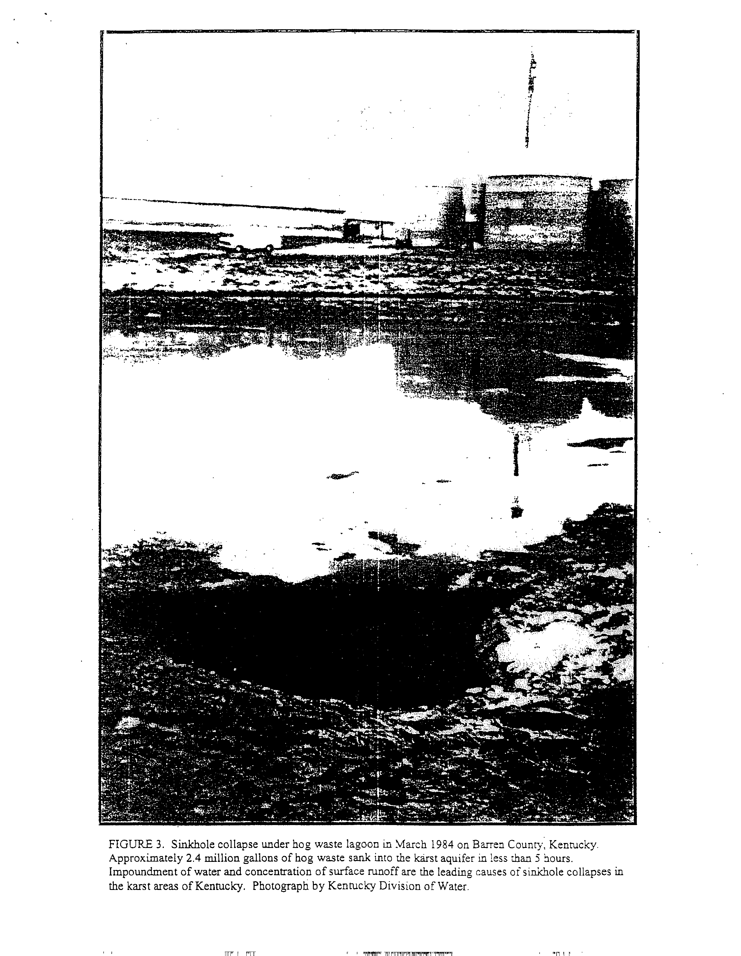
FIGURE 3.
Sinkhole collapse under hog waste lagoon in March
1984 on Barren County,
Kentucky.
Approximately 2.4 million gallons of hog
waste sank into
the
kArst aquifer in less than
5
hours.
Impoundment of water and concentration of surface runoff are the
leading causes of sinkhole collapses in
the
karst areas ofKentucky. Photograph by Kentucky Division of Water
vwwF
rwv
-pfv~
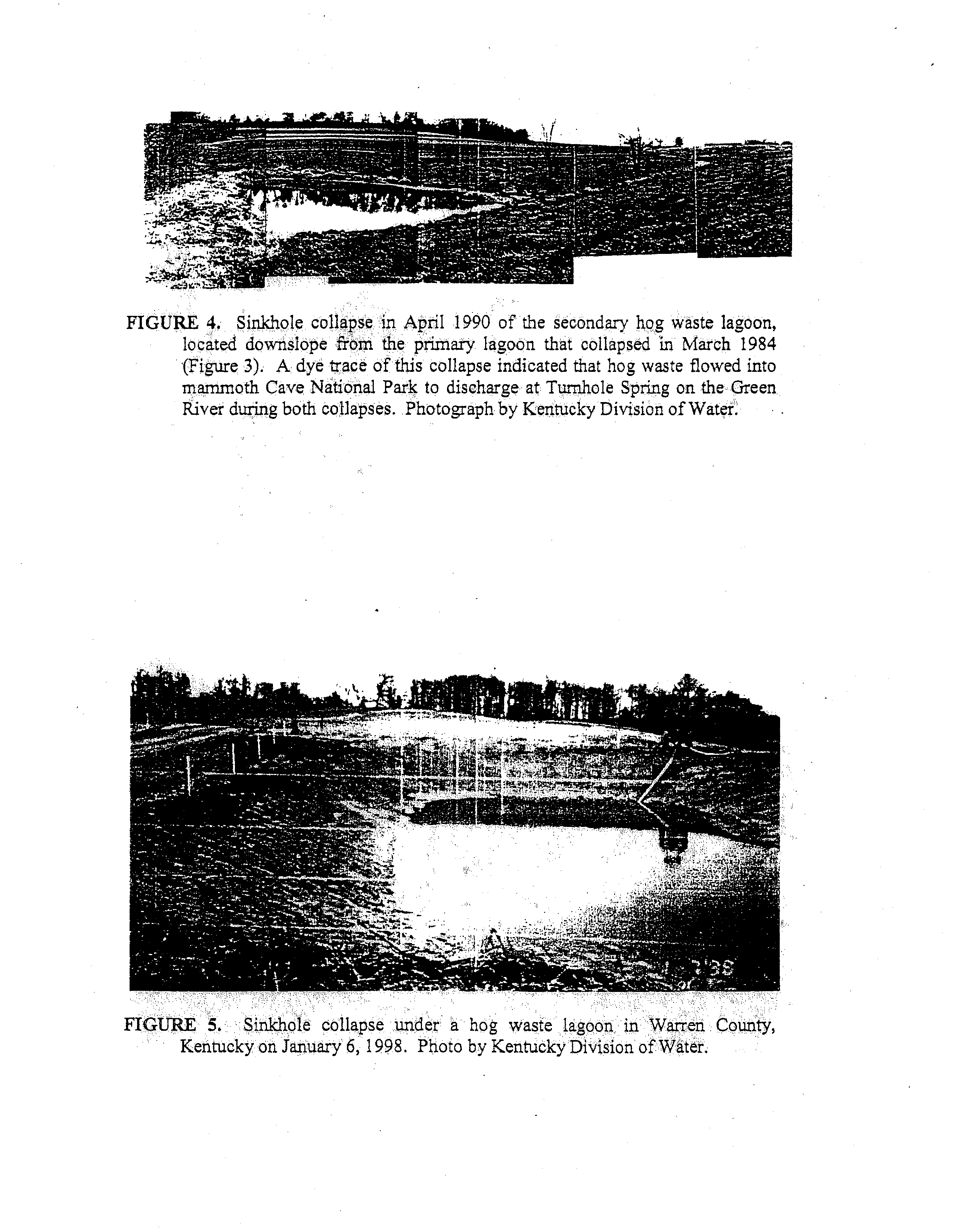
FIGURE 4.
Sinkhole
collapse
in
April
1990
of the
secondary
hog
waste
lagoon,
located
downslope
from
the primary
lagoon
that
collapsed
in
March
1984
(Figure 3).
A dye trace of this collapse indicated that hog waste
flowed into
mammoth Cave National
Park
to
discharge at Turnhole
Spring on the Green
River during both collapses.
Photograph by Kentucky Division of Water.
FIGURE
5.
Sinkhole collapse
under
a
hog
waste
lagoon
in
Warren
County,
Kentucky on January 6,
1998.
Photo by Kentucky Division of Water.
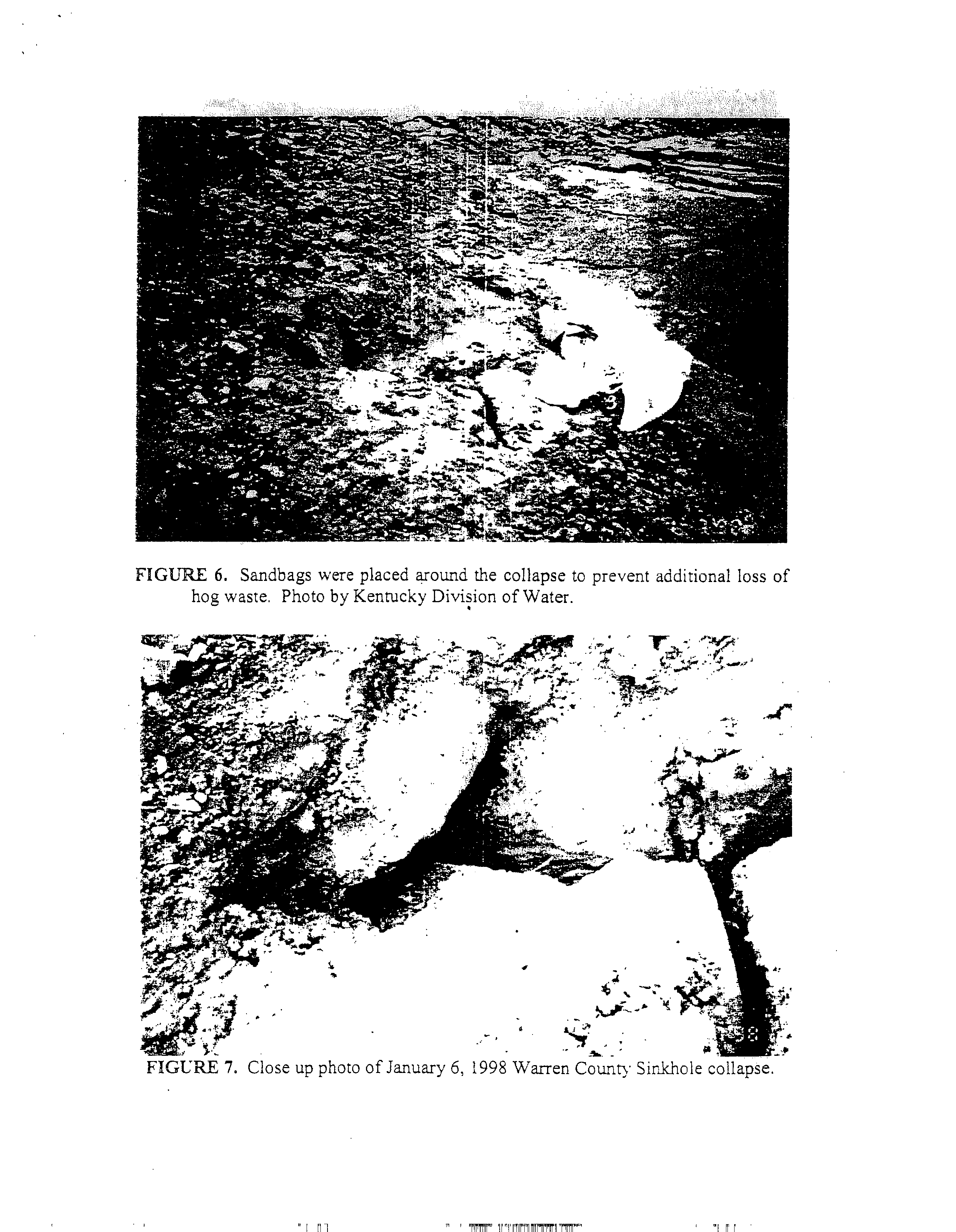
FIGURE
6.
Sandbags were
placed around the collapse
to
prevent additional
loss of
hog waste.
Photo by Kentucky Division of Water.
•1.
3.
..
FIGLRE
7
1998 Warren County
Sinkhole collapse.
Close up photo ofJanuary
6,
-.
—
~0w—
~
-
-.
.
—
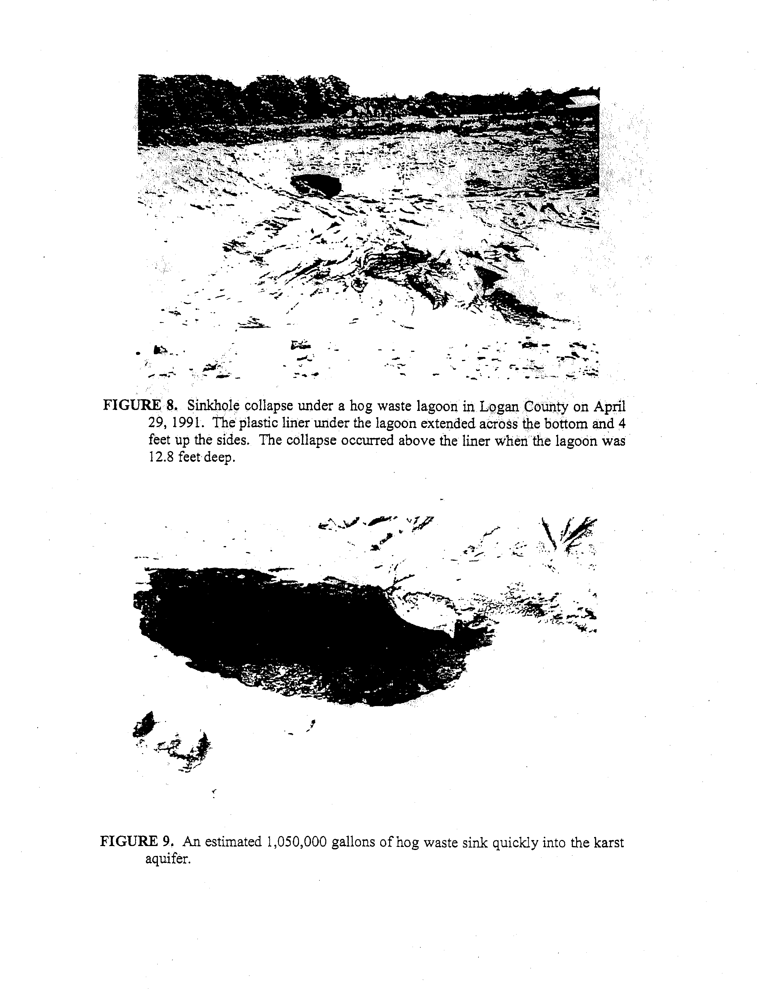
FIGURE
8.
Sinkhole collapse under
a hog waste lagoon in
Logan County on April
29, 1991.
The plastic liner under the lagoon extended across the bottom and 4
feet up the sides.
The collapse
occurred above the liner when the lagoon was
12.8 feet deep.
A
FIGURE 9.
An estimated 1,050,000
gallons ofhog waste sink quickly into the karst
aquifer.
—t
—
-•1
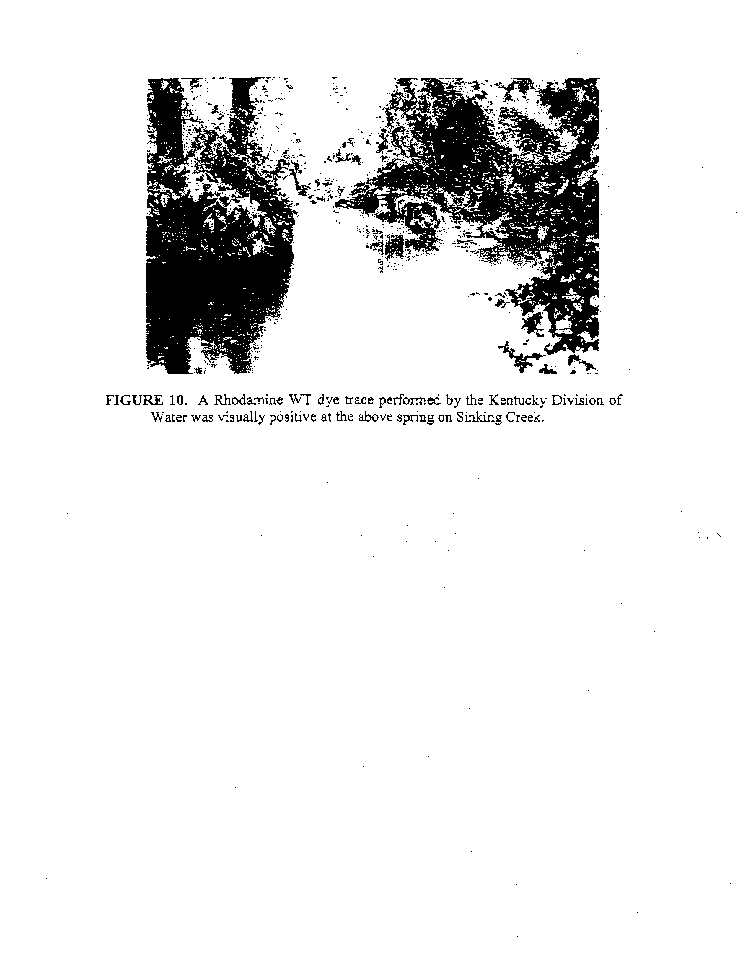
FIGURE
10.
A
Rhodamine WT dye trace
performed by the Kentucky Division of
Water was visually positive at the above spring on Sinking Creek.
pond was
12.8 feet deep along the side but above the liner.
The collapse then expanded
to
drain the entire pond.
A dye trace using Rhodamine WT
dye was
performed by the
Kentucky Division ofWater and visually observed at a nearby spring on Sinking Creek.
The
Kentucky Division ofWater recommended that the
hole
be repaired and that a .20
mu
or thicker liner be installed
to above the high water line ofthe pond.
Hog waste
lagoons
do
not have to
experience
catastrophic sinkhole collapses
to
contaminate karst
aquifers. Leakage
can
result
in contamination of karst
aquifers
and
surface
streams.
Figures
11
through
18
show
dye
traces
of two
leaking
hog
waste
lagoons
in
Logan
County,
Kentucky.
The
leakage from
surface lagoons
appears
to
be
through
macropores
(macrotubes).
These
tubes through the
soil
can
be
made
by
desiccation cracks, worms or tree roots which rot and leave
small tubes through the
soil.
If these tubes reach the epikarst, a very high permeability zone in the vicinity ofthe soil
-
bedrock
contact,
this
permits
water
to
drain rapidly through
the
low
permeability clay
subsoil into
the karst aquifer below. This
leakage through macrotubes may produce soil
piping that results in a sinkhole collapse. Also, the practice of excavating the soil for the
lagoon
tends
to
reduce
the
thickness
of soil
above
existing regolith
(unconsolidated
material above bedrock) arches.
This greatly increases the chances ofa sinkhole collapse
above an existing regolith arch.
There are thousands ofregolith arches per square mile in
most karst areas.
Plates
I
and 2
are maps of the karst
areas of Kentucky.
It shows that
over one half ofthe Commonwealth is underlain by carbonate rock with varying degrees
ofkarstification.
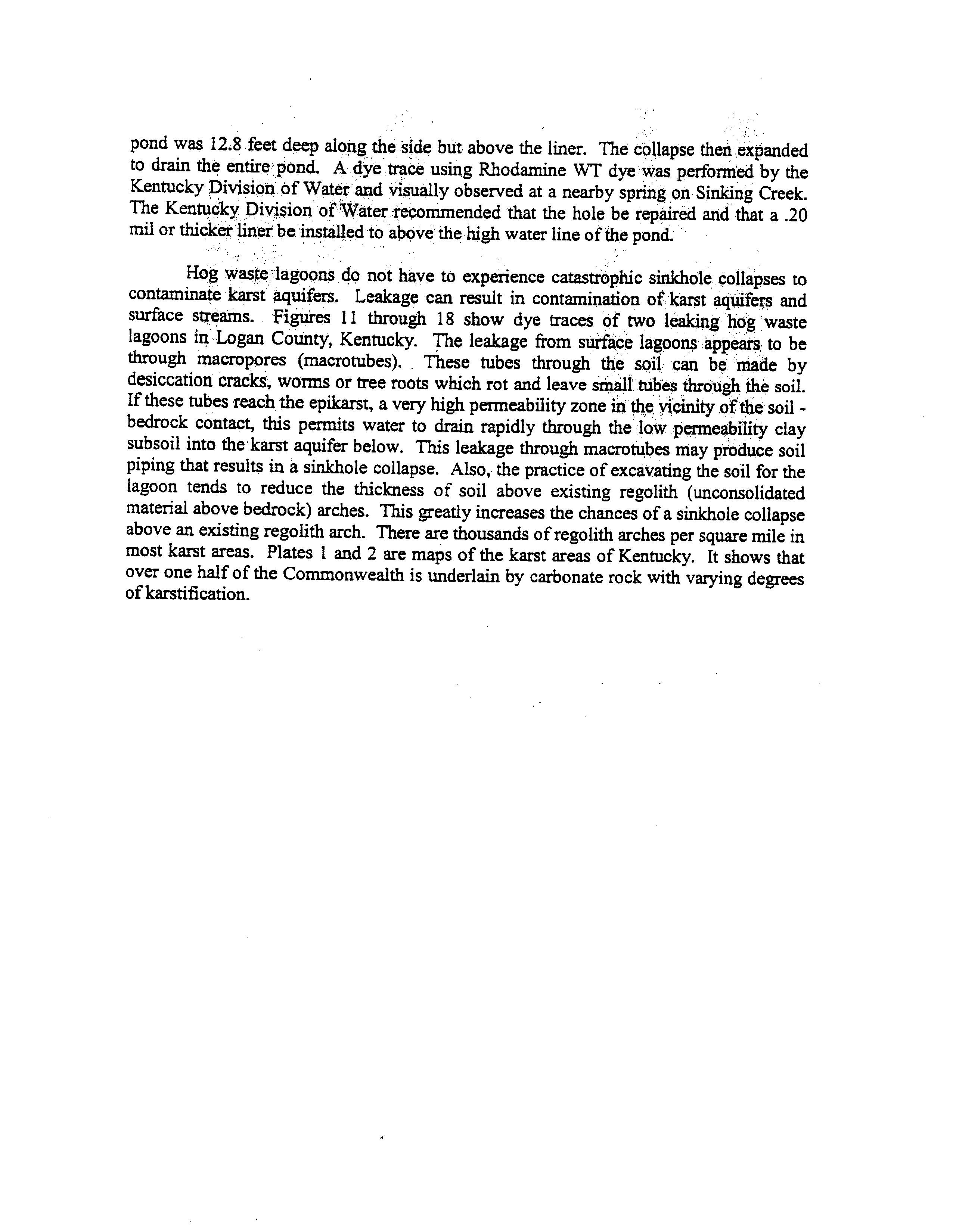
FIGURE
11.
Black
Spring as
it
flows
into
a
spring fed clear stream.
This stream sinks into
a
cave
about 300
feet downstream of Black
Spring.
FIGURE
12,
Water samples
collected
from Black
Spring (right) and
from
the
clear
stream upstream from
Black Spring (left).
I
FIGURE
13.
Euthrophication downstream from Black
Spnng before
the
stream sinks into
a cave.
FIGURE
14.
Rhodamine
WT dye trace of one of the
four hog
waste lagoons.
~UtU3~
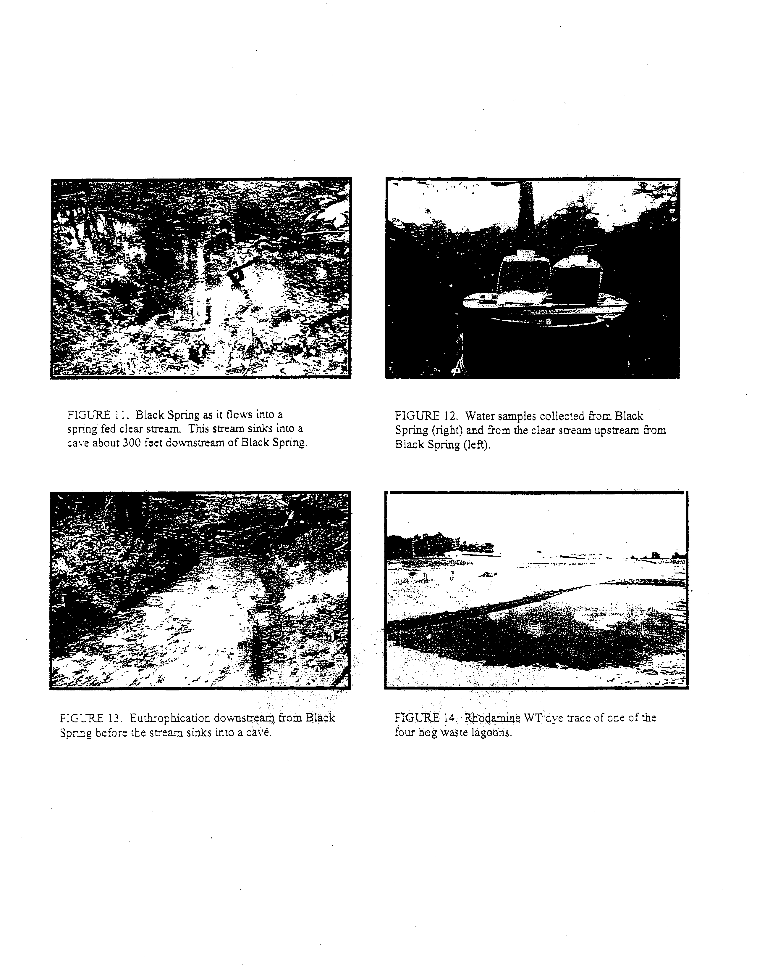
FIGURE
16.
Two of the four waste lagoons
were
tested for leakage
by injecting R.hodamine WT
and Fluorescein dyes.
The map shows
the
approximate route taken by the two dyes from the
hog waste lagoons
to Black Spring on
the clear
surface steam.
This sfleam sinks into a cave
and
then resurges at a spring on
the nearby river.
FIGURE
17.
Quantitative dye breakthrough curves
for Rhodanaine WT and Fluorescein dyes
at Black
Spring.
First arrival
for Fluorescein was
16
hours
and for Rhoda.mine WT it was 20
hours.
1
•
fl.
10~
•0:
•~c..*
I’
‘
/‘~•\
‘I
I
~
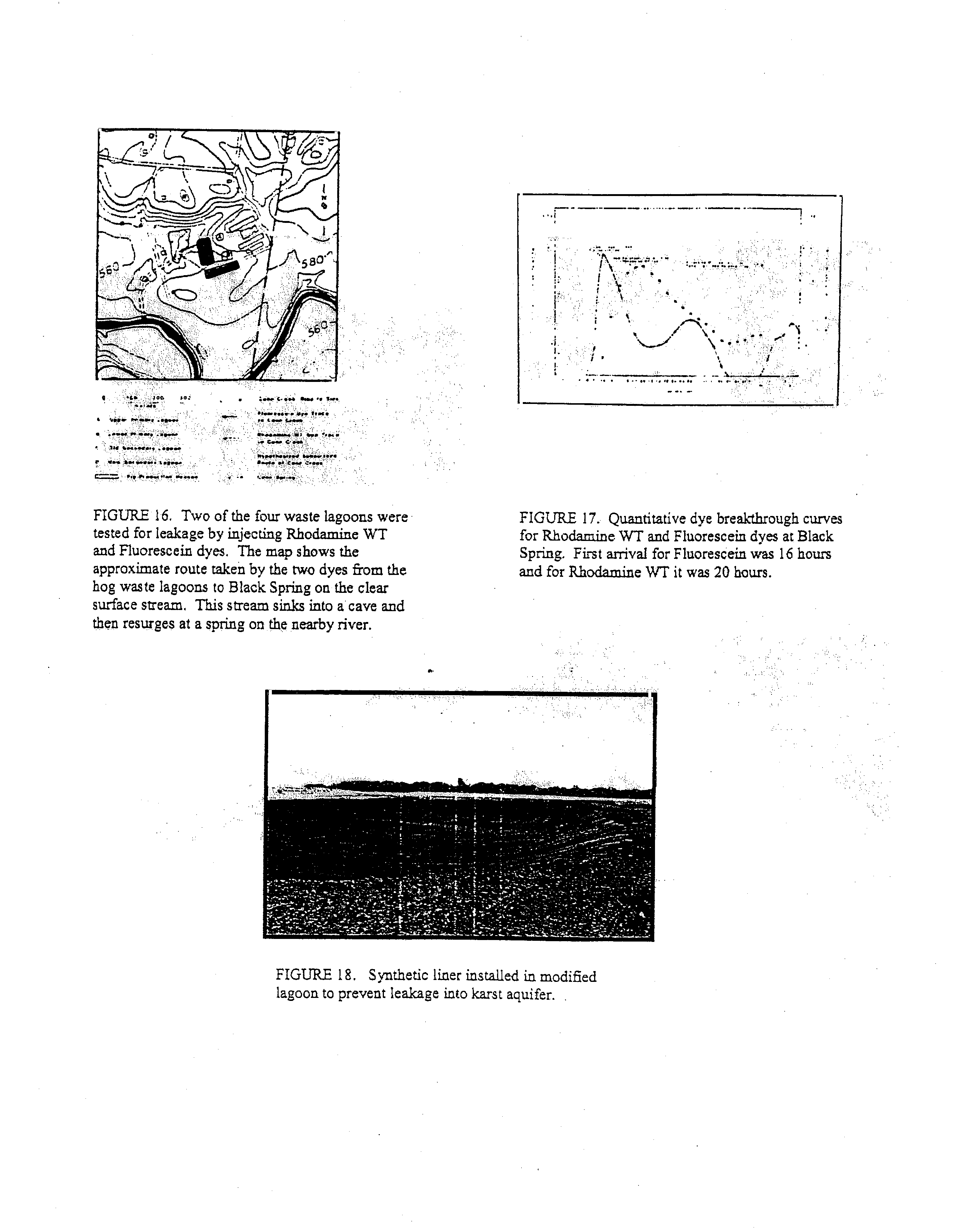
FIGURE
18.
S~thetic liner installed in modified
lagoon to prevent leakage into karst aquifer.
CONCLUSIONS
All hog waste
lagoons built upon karst
should
have a synthetic
liner (at least 60
mis
thick)
installed ‘to prevent leakage and possibly
sinkhole collapses.
Also,
a
karst
hydrogeologic investigation that includes a dye trace should be
performed
to identify the
receiving spring, or springs,
in the
event of a
leak.
The spring(s) should
then
be tested
periodically for groundwater contamination associated with hog waste.
S
CQNSTRUCTThJG NEW MANURE STORAGE SYSTEMS
IN THE KARST REGION
draft guidance document 2/8/99
Minnesota Pollution Control Agency
SUMMARY
Construction of large liquid
manure
storage
systems
has
greatly increased
during the
past
decade
in
the
karst region of southeastern Minnesota.
Soil subsidence
under
a liquid
manure storage system
could breach the integrity ofthe
liner, causing either a catastrophic
release of manure
to, ground water or a
slow
undetected manure
seepage
problem.
The
probability ofsoil subsidence varies greatly across this region ofthe state.
Construction of
new
liquid
manure storage
systems
in
higher
risk
areas for
sinkhole
formation creates
heightened
concerns
about
water quality protection. To minimize
the
risks of siting new
manure
storage
systems
in the
karst
region,
the
Minnesota
Pollution Control Agency
has
developed and
implemented
a policy
to
evaluate relative
risks of soil
subsidence prior
to
approving
feedlot construction
permits. Permitting decisions depend on
the
results of a
site-specific karst investigation, the proposed volume of manure to be stored and the type of
liner proposed
for the storage system. Precautionary measures required of some livestock
producers
have
included
one or
more of
the
following:
locating the
feedlot
in
a
less
vulnerable area, using less permeable liner materials, and rerouting roof runoff waters.
BENEFITS AND RISKS TO WATER QUALITY
Benefits ofLivestock andManure Storage Structures
Livestock agriculture has some water quality benefits in the karst region
that help to offset some of the
risks to water quality.
Manure applied to land planted to row crops
can reduce soil erosion.
Hay-land and
pasture
associated with
cattle
operations
results
in
very little soil erosion and pesticide
transport
in
this
region of steeply sloping soils.
The trends to
construct new and expanded
feedlot facilities and the
associated
liquid
manure storage
systems typically result in
further protection of surface water quality. Liquid
manure storage
structures
increase
management flexibility, making it easier to apply at proper rates and to avoid winter-time
manure
application. Also, may
of
the older
feedlot facilities
are
located
adjacent
to
streams
and do not
have
containment of manure or
manure-contaminated
runoff.
Most facilities with new liquid
manure storage
structures have total containment of manure such that there is
no manure discharge into
surface waters from
rainfall and snowmelt. Also, the liquid manure in containment structures
is usually injected below the soil
surface and is
less subject to surface runoff compared to the typical soil surface spreading practices of many
feedlot facilities without liquid manure storage.
Risks ofManure Storage Systems in Karst Regions
While there are a number ofwater quality benefits associated with
liquid manure storage systems, there
are also several heightened risks.
One possible risk
is
the failure of the walls of the manure storage system
to hold the manure with a resulting river of manure flowing down a valley and into a stream.
This has not
been known to occur in Minnesota, likely due in
part to engineering review and regulation of construction
activities.
What has occurred
in
Minnesota are
basin overflows
and
intentional discharges
from
manure
storage structures.
Enforcement of such
violations has increased
substantially
during recent
years
in
an
effort to curb blatantviolations and mismanagement.
-
Three potential water quality risks associated with liquid manure storage systems in the karst
region
include:
1)
seepage
of
contaminants
through the
liner
and underlying soil to
fractured
bedrock and
subsequently to
ground
water;
2)
soil subsidence below the structure which breaches-the
in4egrity of the
concrete,
geosynthetic or soil
liner, causing a slow and
perhaps
undetectable
leaking of manure from
the
storage system to ground water; and 3) a large
sinkhole forming below a manure storage system
leading to a
rapid flow
of manure
into
ground water or causing a
collapse
in
a basin sidewall
and a pouring
out
of
manure onto the ground surface.
Manure entering ground water will discharge into streams within a period of time ranging from hours to
decades
depending on
the site-specific hydrogeology. The karst region
of Minnesota maintains a
large
number of
high
quality trout
streams.
A rapid discharge of a large quantity of manure into a stream will
destroy
the
aquatic life for
a stretch
of the stream and also result in increased nutrient loading
into
the
receiving waters of the Mississippi River system.
Manure
which flows in the ground water
for a
longer
period before
discharging
into
streams will be more diluted and may
not destroy
aquatic
life,
but
will
threaten drinking water supplies
as
it
travels toward. the
stream,
and
contribute
to
stream pollution
upon
discharge.
Risks associated with slow seepage through the liner are reduced somewhat by Minnesota requirements
for
a minimum ten-foot separation distance between the bottom ofstandard reinforced concrete and earthen
manure storage structures and underlying bedrock.
If a composite liner or other nearly impermeable
liner
system is used, then the required miniipum separation distance
from bedrock is five feet. Requirements to
minimize
the risks associated with so~i subsidence
as new liquid
manure storage systems are constructed in
the karst region is the primary subject of these guidelines.
EVALUATING RISKS OF SOIL SUBSIDENCE
Learning experiences from sinkholesforming under municipal wastewater treatmentponds
Between
1974
and
1992,
sinkholes opened below three of the twenty-two municipal wastewater
treatmcnt ponds
in
Minnesota’.3 karst
region.
Sinkholes developed
in Altura’s ponds
in
1974
during
construction and in
1976 when it first filled to capacity (Alexander and Book,
1984).
A sinkhole developed
in a Lewiston pond in
1991
after eighteen years of use (Jannik et al.,
1992).
Several sinkholes developed
in
a Belichester pond
in
1992
after twenty-two years of use (Alexander et al.,
1993).
The amounts of partially
treated wastewater draining into sinkholes at the three respective sites was 3.7, 2.3, and 7.7 million gallons.
The ponds
were
constructed of earthen materials with a designed seepage rate not to exceed
3500
gallons
per acre per day. Several sinkholes
are
located within
about
a mile
from
all
three sites,
yet no
sinkholes
have been identified within a quarter of a mile from the sites.
These
failures clearly
demonstrate
the potential for sinkholes to
develop
in
southeastern
Minnesota
when
large quantities of liquids are stored
in sinkhole prone
areas with minimal barriers
between the liquid
and underlying materials.
Similar problems could develop when storing liquid manure on top of permeable
liner materials. However,
there are several
notable
differences between these failed municipal wastewater
treatment systems and manure storage systems currently being constructed. The maximum allowable design
seepage rate for manure storage systems
is
500
gallons/acre/day,
seven
times
less
than the
old
municipal
wastewater ponds.
These
design seepage rates assume that the ponds
remain
full
and they do
not
account
for seepage reductions
caused
by
the physical, chemical and biological sealing
which takes
place at the
2
manure/soil interface.
In
addition, the size of even the largest manure storage
systems
is
smaller than the
municipal ponds.
These differences between the failed municipal systems and manure storage structures are
worth recognizing, but they are not great enough to warrant complete disregard of
the risks
associated with
siting liquid manure
storage systems
in
sinkhole
prone areas.
It
is
also
important
to
note
that
the
contaminant concentrations in
manure
are
often over
100
times greater
than municipal
wastewater
pond
liquids, and thus the
environmental
consequences of a catastrophic
manure release could
be
much worse
than municipal
pond failures.
Sinkhole Probability Mappingand Research
Sinkhole mapping and research completed during the past two decades has made it easier to determine
the relative soil subsidence risks when siting new liquid manure storage
systems in Southeastern Minnesota.
Sinkhole probability maps
have
been
completed
for three counties
(Dalgleish
and
Alexander,
1984;
Alexander and Maki,
1988;
Witthuhn and Alexander,
1995) and additional
hydrogeologic investigation has
been conducted in
the
other
karst
areas.
The probability
of sinkhole formation has been
found
to
vary
tremendously across the region.
Some areas have
in excess of 50 sinkholes per square mile and other areas
have
no sinkholes.
Often
high density clusters of sinkholes are adjacent to areas with
scattered individual
sinkholes. Bedrock
composition, topographic position
in
the landscape and thickness
of glacial
materials
over bedrock have all
been found to affect the likelihocsd ofsinkhole formation.
Most sinkholes in southeastern Minnesota appear where there
is
less than 50
feet of surficial cover over
carbonate
and sandstone
bedrock.
The
proximity
of nearby sinkholes remain the single
best predictor of
new sinkhole development (Witthuhn and Alexander,
1995).
Magdalene and Alexander (1995)
concluded
that
on the
scale of several
kilometers,
new sinkholes
in
Winona County tend to
develop
in
the areas of
existing sinkholes,
especially near newl~’developed sinkholes.
The
risk of soil subsidence
has
generally
been found to
increase
in areas of po’~ided or intermittently
flowing water,
and
in
areas with
indications of
more extensive karstification, including
areas with disappearing streams,
caves,
dry
valleys,
springs and
solution cavities.
REGULATORY POLICY TO
MINIMIZE RISKS
Gverview
The
rapid
increase
in
the
construction
of
large liquid manure
storage
structures
in
southeastern
Minnesota,
coupled
with
experiences
of sinkhole development in
three
municipal
wastewater
treatment
ponds, prompted the Minnesota Pollution Control Agency (MPCA) to consider measures to
minimize risks
associated with construction of liquid or semi-solid manure storage structures in sinkhole prone areas.
Beginning in
1995, the MPCA has worked to develop and implement a policy to reduce
environmental
risks associated with construction of liquid manure storage systems in sinkhole
prone areas, yet maintain the
feasibility of constructing manure storage systems throughout much
of the karst
region..
These guidelines
were developed so that a general indication
of environmental risk can be readily evaluated in karst regions
and
precautionary measures
can
be taken.
The
information used to
evaluate
the
potential
for
sinkhole
formation,
and, in general, how this
information is
used
in making permitting decisions, is described on the
following pages. Specific
permitting
decisions are made
on
an individual
case-by-case
basis after
considering
numerous
factors. The
intent
of the
guidelines
is to allow the producers and their
technical
advisors to understand sinkhole risk considerations early in the planning and
site
selection process,
prior to
substantial investment of time and money.
3
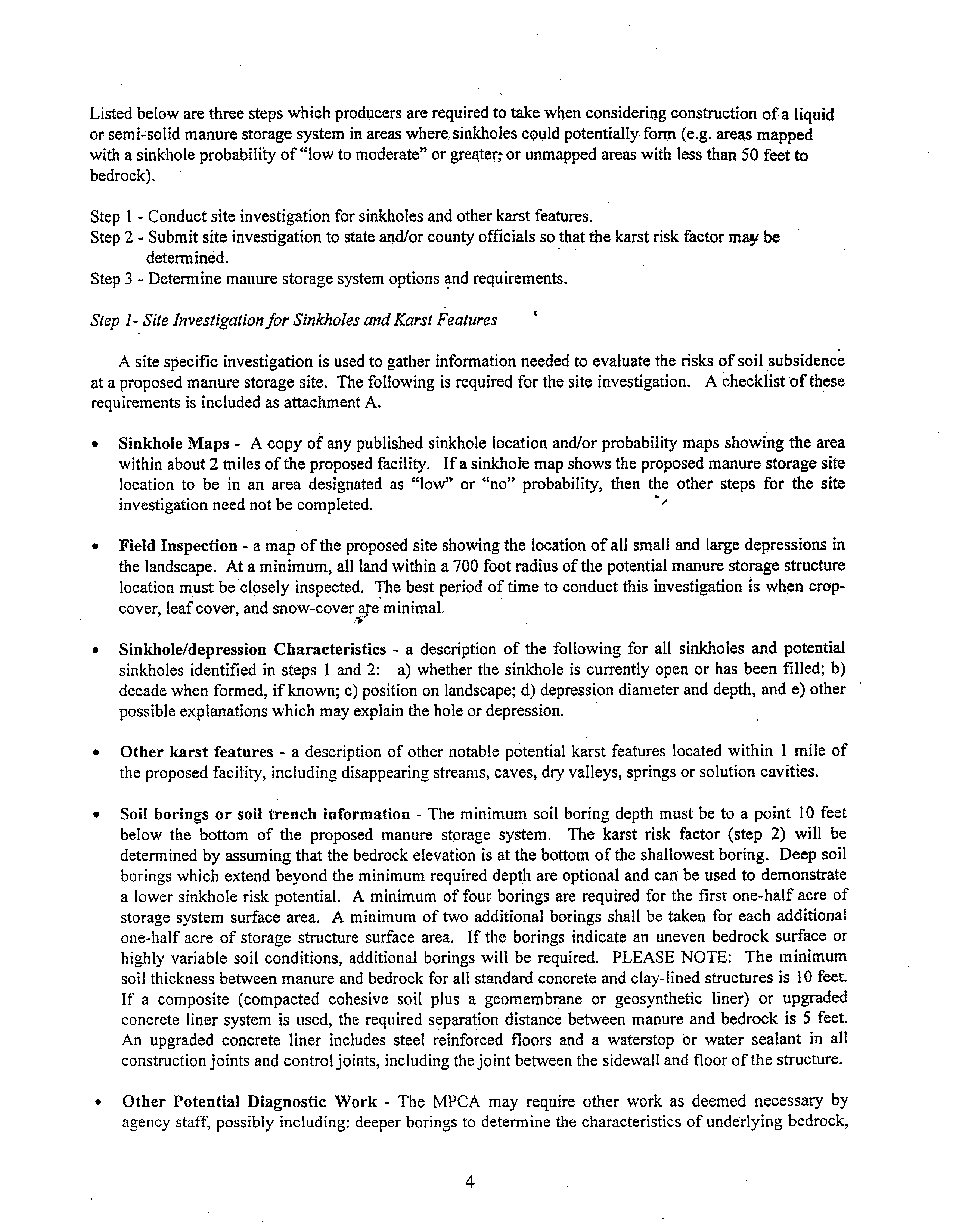
Listed below are
three steps which producers are required to take when considering construction ofa liquid
or semi-solid manure storage system
in areas where sinkholes could potentially form
(e.g. areas mapped
with a sinkhole probability of “lowto moderate” or greater~ or unmapped areas with less than 50
feet to
bedrock).
Step
I
-
Conduct site investigation for sinkholes and other karst features.
Step 2
-
Submit site investigation to state and/or county officials so that the karst risk factor may be
determined.
Step
3
-
Determine manure storage system options
and requirements.
Step 1- Site Investigationfor Sinkholes and Karst Features
A site
specific investigation is used to gather information needed to evaluate the risks of soil subsidence
at a proposed manure storage site.
The following is required for the site investigation. A checklist of these
requirements is
included as attachment A.
•
Sinkhole
Maps
-
A copy of any published sinkhole location and/or probability maps showing the area
within
about 2 miles of the proposed facility.
If a sinkhole map shows the proposed manure storage site
location to be in an
area
designated
as
“low’~ or
“no~~
probability, then the other steps
for the
site
investigation need not be completed.
•
Field Inspection
-
a map of the proposed
site showing the location of all small and large depressions in
the landscape.
At a minimum, all land within a 700 foot radius of the
potential manure storage structure
location must be closely inspected.
The best period
of time to conduct this investigation is when crop-
cover, leaf cover, and snow-cover~e
minimal.
•
Sinkhole/depression
Characteristics
-
a description
of the
following for
all
sinkholes
and potential
sinkholes identified in steps I and 2: a) whether the sinkhole
is
currently open or has
been filled; b)
decade when formed, if known; c) position on landscape; d) depression diameter and depth, and e) other
possible explanations which may explain the hole or depression.
•
Other knrst features
-
a description of other notable
potential karst features located within
1
mile
of
the proposed facility, including disappearing streams, caves, dry valleys, springs or solution cavities.
•
Soil borings
or soil trench information
-
The minimum soil boring depth must be to a point
10
feet
below the bottom
of
the
proposed
manure
storage system. The
karst risk
factor (step
2) will be
determined by assuming that the bedrock elevation is
at the bottom of the shallowest boring. Deep soil
borings which extend beyond the minimum required depth are optional and can
be used to
demonstrate
a lower sinkhole risk potential. A minimum of four borings
are
required for the
first one-half acre
of
storage
system
surface area. A minimum of two additional borings shall
be taken
for each additional
one-half acre
of storage structure surface
area.
If the
borings
indicate an uneven bedrock surface or
highly
variable soil conditions,
additional
borings will
be
required.
PLEASE NOTE: The
minimum
soil thickness between manure and bedrock for all standard concrete and clay-lined structures is
10 feet.
If
a composite (compacted
cohesive
soil plus a geomembrane or
geosynthetic
liner) or
upgraded
concrete liner system is used,
the required
separation
distance between manure and bedrock
is
5
feet.
An
upgraded concrete liner includes steel
reinforced
floors and a waterstop or
water
sealant
in all
construction joints and control joints, including the joint between the sidewall and floor of the structure.
•
Other Potential
Diagnostic
Work
-
The
MPCA
may require
other work as deemed
necessary
by
agency
staff, possibly including: deeper borings to determine the characteristics of underlying bedrock,
4
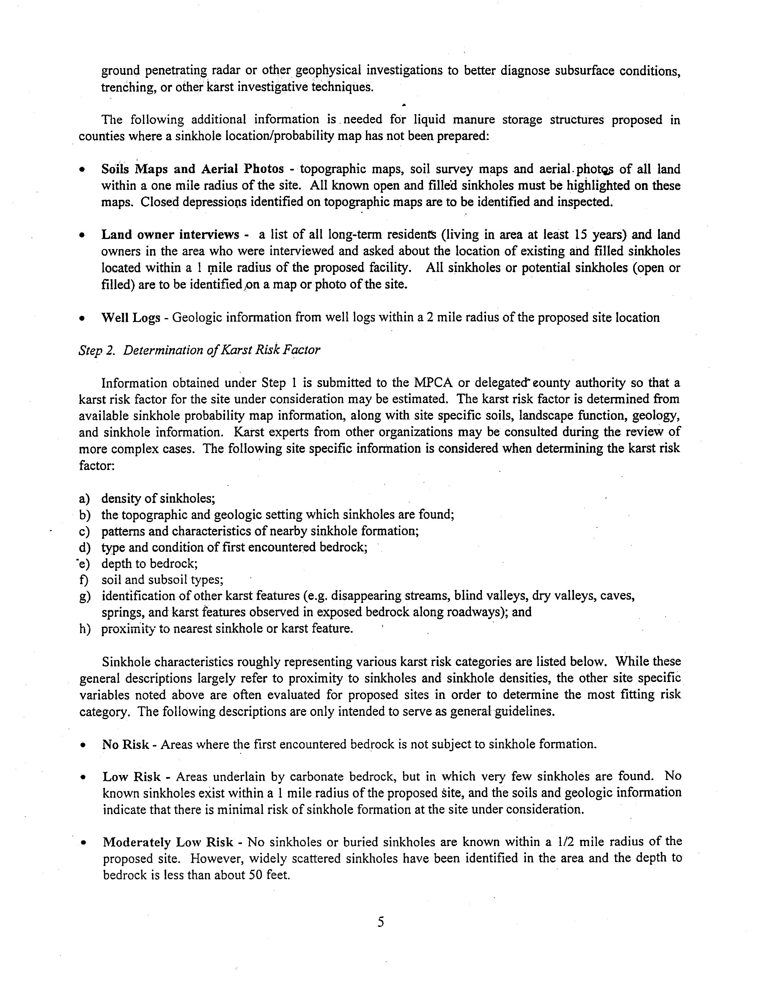
ground
penetrating radar or other
geophysical
investigations to
better diagnose
subsurface conditions,
trenching,
or other karst investigative techniques.
The
following
additional
information
is
needed for
liquid
manure
storage
structures
proposed
in
counties where a sinkhole locationlprobability map has not been prepared:
•
Soils
Maps
and Aerial
Photos
-
topographic maps, soil survey maps and aerial. phot~
of all land
within
a one mile radius of the site.
All known open and filled sinkholes must be highlighted on
these
maps.
Closed depressions identified on topographic maps are to be identified and inspected.
•
Land
owner
interviews
-
a
list
of all
long-term
residents (living in area
at least
15
years) and
land
owners
in
the area who were interviewed and asked
about the location of existing and filled sinkholes
located within a
1
inile
radius of the proposed facility. All sinkholes
or potential
sinkholes (open or
filled) are to be
identified
1on amap or photo ofthe site.
•
Well Logs
-
Geologic
information from well logs within a 2 mile radius of the proposed site location
Step 2.
Determination ofKarst RiskFactor
Information obtained under Step
I
is
submitted to the MPCA or delegated county authority so that a
karst risk factor for the site under consideration may be estimated. The karst risk factor is
determined from
available sinkhole probability map information, along with site specific soils, landscape function, geology,
and sinkhole
information.
Karst experts from other organizations
may be
consulted
during the review of
more complex cases.
The
following site specific information is considered when determining the karst risk
factor:
a) density of sinkholes;
b)
the topographic and geologic setting which sinkholes are found;
c) patterns and characteristics of nearby sinkhole formation;
d) type and condition of first encountered bedrock;
~e) depth to bedrock;
f) soil and subsoil types;
g)
identification of other karst features (e.g. disappearing streams, blind valleys, dry valleys, caves,
springs, and karst features observed
in exposed bedrock along roadways); and
h)
proxiii’ityto nearest sinkhole
or karst feature.
Sinkhole characteristics
roughly representing various karst risk categories
are listed
below.
While these
general
descriptions largely
refer
to
proximity
to
sinkholes
and
sinkhole
densities,
the
other
site
specific
variables
noted
above
are
often
evaluated
for
proposed sites in
order
to
determine
the
most
fitting risk
category. The following descriptions are only intended to serve as general-guidelines.
•
NoRisk
-
Areas where the first encountered bedrock is not subject to sinkhole formation.
•
Low
Risk
-
Areas underlain
by
carbonate
bedrock,
but
in
which very few sinkholes are found. No
known sinkholes exist within a
1
mile radius of the proposed site, and the soils and geologic information
indicate that there is minimal risk of sinkhole formation at the site under consideration.
•
Moderately
Low Risk
-
No
sinkholes or
buried
sinkholes
are
known
within
a
1/2
mile radius of the
proposed
site.
However,
widely scattered sinkholes have been identified
in
the area and the depth to
bedrock
is
less
than about 50 feet.
5
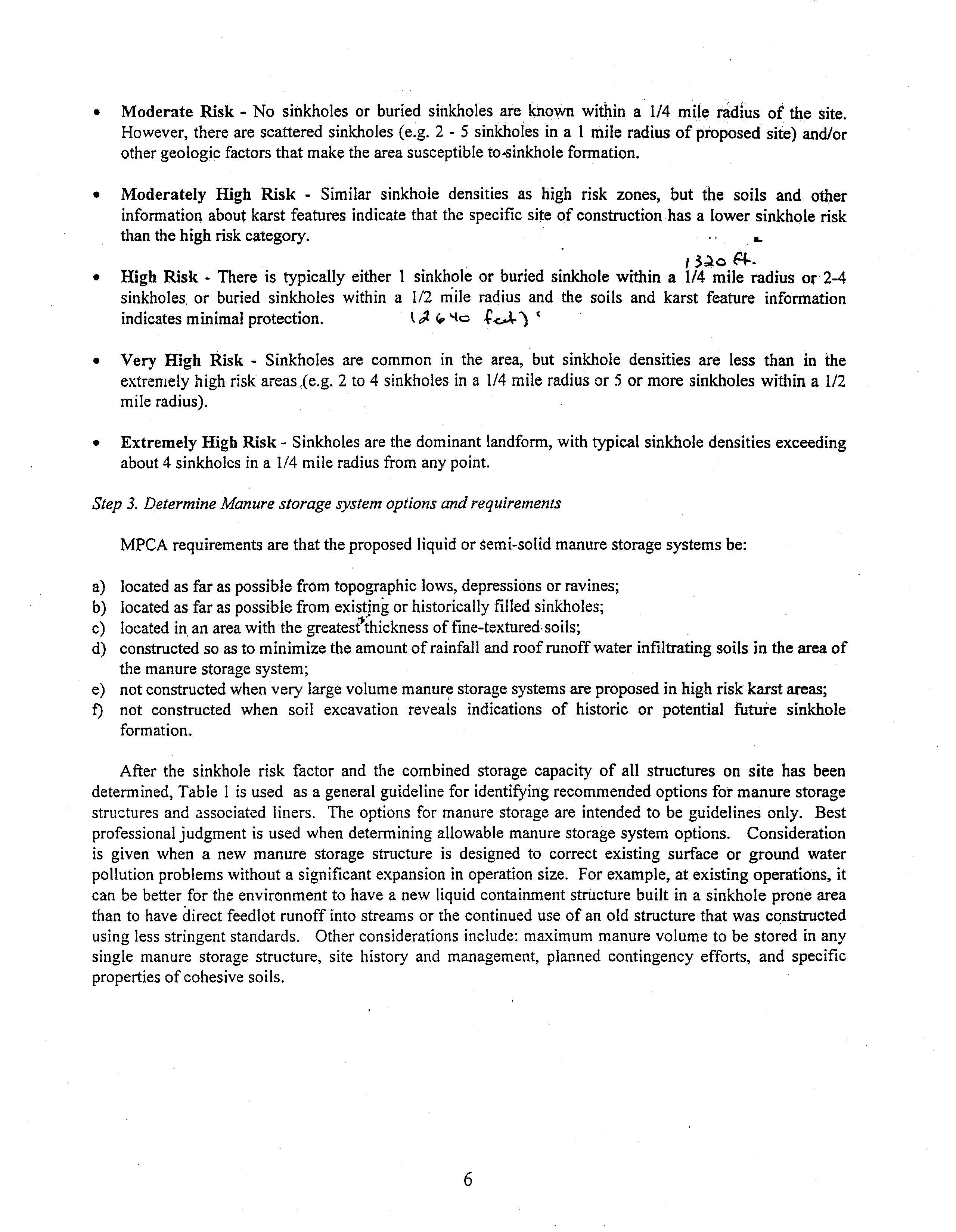
•
Moderate Risk
-
No
sinkholes
or buried
sinkholes
are
known
within
a
1/4
mile
radius
of the
site.
However,
there are scattered sinkholes (e.g.
2
-
5
sinkholes in a
1
mile radius of proposed
site) and/or
other geologic factors that make the area susceptible to-sinkhole formation.
•
Moderately
High
Risk
-
Similar
sinkhole
densities
as
high
risk
zones,
but the
soils
and
other
information about karst features indicate that
the
specific site of construction has a lower sinkhole risk
than the high risk category.
a.
3~o
p4-.
•
High Risk
-
There is
typically
either
I
sinkhole
or
buried
sinkhole within a
1/4
mile
radius or 2-4
sinkholes or
buried
sinkholes
within
a
1/2
mile radius and the soils and
karst
feature
information
indicates minimal protection.
~24.
‘4~
~V)
•
Very
High
Risk
-
Sinkholes are common
in
the
area,
but sinkhole
densities
are less
than
in the
extremely high risk areas (e.g. 2 to 4 sinkholes in
a
1/4 mile radius or
5 or more sinkholes within a
1/2
mile radius).
•
Extremely High Risk
-
Sinkholes
are the dominant
landform, with typical sinkhole densities
exceeding
about 4 sinkholes in a
1/4 mile radius from any point.
Step
3. Determine Manure storage system options and requirenlents
MPCA requirements are that the proposed liquid or semi-solid manure storage systems be:
a) located as far as
possible from topographic lows, depressions or ravines;
b)
located as far as possible from existjn~ or historically filled sinkholes;
c) located in
an area with the greatest thickness of fine-textured-soils;
d)
constructed so as to minimize the amount of rainfall and roof runoff water infiltrating soils in the area of
the manure storage system;
e) not constructed when very large volume manure storage-systems-are-proposed
in high risk karst areas;
f) not constructed
when
soil
excavation
reveals
indications
of
historic or
potential
future
sinkhole
formation.
After the
sinkhole
risk
factor
and the combined storage capacity of
all
structures
on
site
has been
determined, Table
1
is used
as a general guideline for identif~’ingrecommended options for manure storage
structures and
associated
liners.
The
options
for manure storage
are
intended to be
guidelines only.
Best
professional judgment is
used when determining allowable manure storage system options.
Consideration
is
given when
a
new
manure
storage structure
is
designed to correct
existing surface
or
ground
water
pollution problems without a significant expansion in operation size. For example,
at existing operations,
it
can
be
better for the environment
to have a new liquid
containment structure built
in a sinkhole prone area
than to have direct feedlot runoff into streams or the continued use of an old structure that was
constructed
using
less stringent standards.
Other considerations include:
maximum
manure volume to be stored
in any
single manure storage structure,
site
history
and management, planned contingency
efforts,
and
specific
properties of cohesive soils.
6
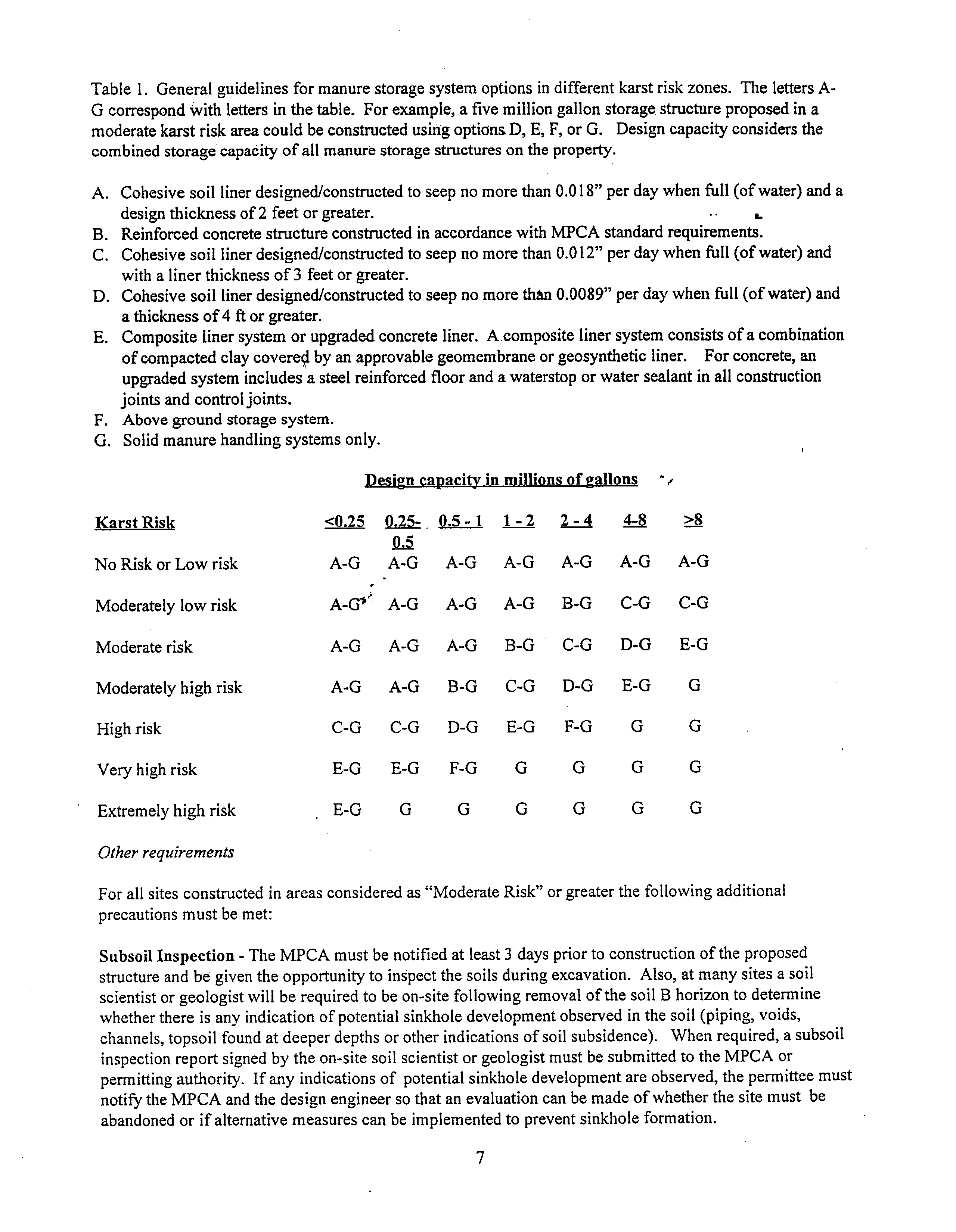
Table I.
General guidelines for manure storage system options in different karst risk zones.
The letters A-
G correspond with letters in the table. For example, a five million gallon storage structure proposed in a
moderate karst risk area could be constructed using options D, E, F, or G. Design capacity considers the
combined storage capacity of all manure storage structures on the property.
A. Cohesive soil liner designed/constructed to seep no more than 0.018” per daywhen full (of water) and a
designthicknessof2feetorgreater.
B.
Reinforced concrete structure constructed in accordance with MPCA standard requirements.
C.
Cohesive soil liner designed/constructed to seep no more than
0.0 12” per day when full (of water) and
with a liner thickness of 3
feet or greater.
D. Cohesive soil liner designed/constructed to seep no more than 0.0089” per day when full (of water) and
athickness of 4 ft or greater.
E.
Composite liner system or upgraded concrete liner. A composite liner system consists of a combination
of compacted clay covere~l by an approvable geomembrane or geosynthetic liner.
For concrete, an
upgraded system includes a steel reinforced floor and a waterstop or water sealant in all
construction
joints and control joints.
F. Above ground storage system.
G.
Solid manure handling systems only.
Design
capacity in millions ofgallons
KarstRisk
<0.25
0.25-
0.5-1
1-2
2-4
4-8
>8
0.5
No Risk or Low risk A-G A-G A-G A-G A-G A-G A-G
Moderately low risk
A-G~
A-G
A-G
A-G B-G
C-G C-G
Moderate risk A-G A-G A-G
B-G
C-G D-G E-G
Moderately high risk A-G A-G B-G
C-G
D-G E-G G
High risk
C-G C-G D-G E-G F-G G G
Very high risk
E-G E-G F-G G G G G
Extremely high risk E-G
G
G
G
G G
G
Other requirements
For all
sites constructed in areas considered as “Moderate Risk” orgreater the following additional
precautions must be met:
Subsoil Inspection
-
The MPCA must be notified at least 3 days prior to construction ofthe proposed
structure and be given the opportunity to inspect the soils during excavation. Also, atmany sites a soil
scientist or geologist will be required to be on-site following removal
ofthe soil B horizon to determine
whether there is any indication of potential sinkhole development observed in the soil (piping, voids,
channels, topsoil found at deeper depths or other indications of soil subsidence>.
When required, a subsoil
inspection report signed by the on-site soil scientist or geologist must be submitted to the MPCA
or
permitting authority.
If any indications of
potential sinkhole development are observed, the permittee must
notify the MPCA and the design engineer so that an evaluation can be made of whether the site must be
abandoned or if alternative measures can be
implemented to prevent sinkhole formation.
7
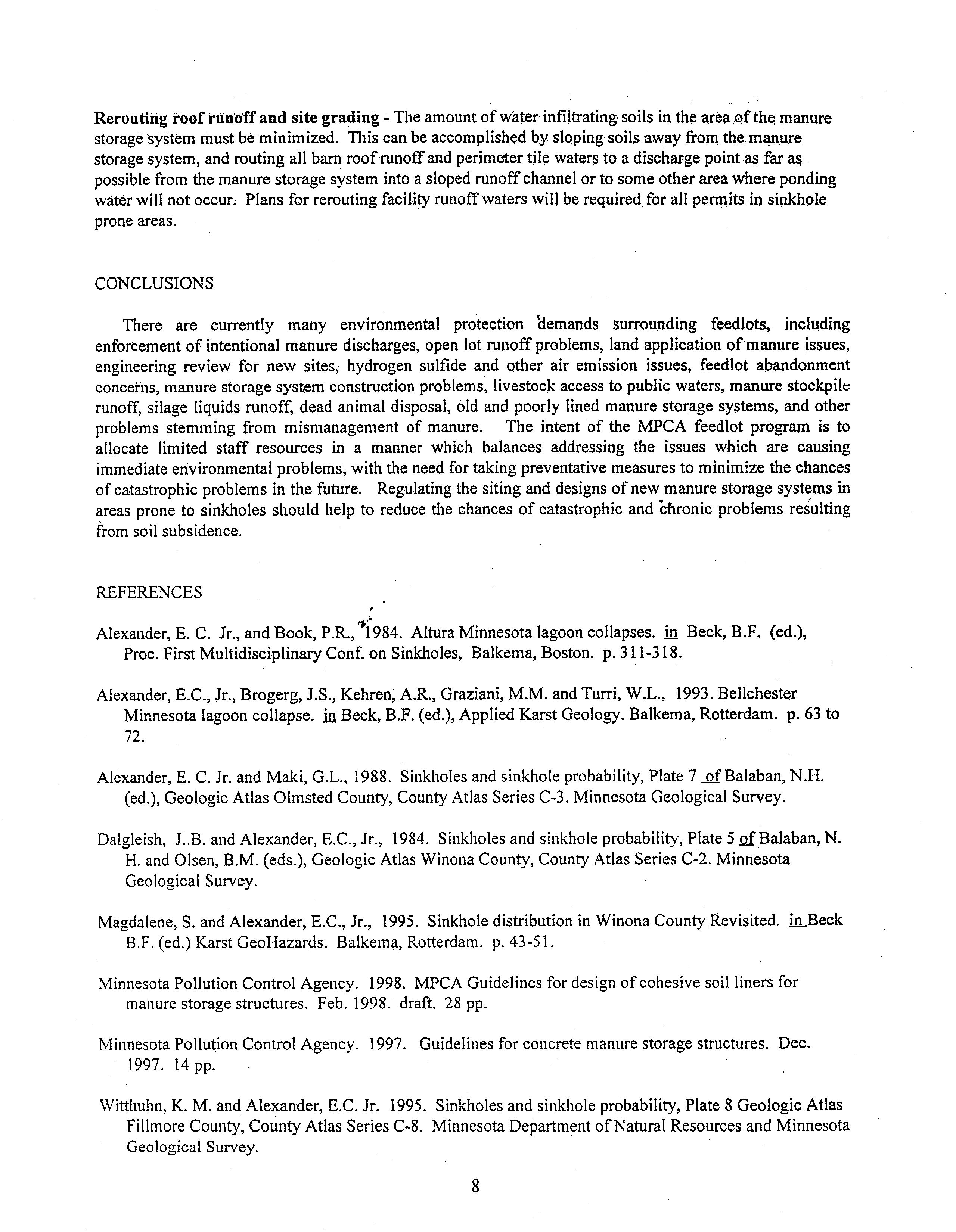
Rerouting roof runoffand site grading
-
The amount of water infiltrating soils in the area of the manure
storage system
must be minimized.
This can be accomplished by
sloping soils away from the manure
storage system, and routing all bam roof runoff and perimeter tile waters to a discharge point as far as
possible
from the manure storage system into a sloped runoff channel or to some other area where ponding
water will not occur.
Plans for rerouting facility runoff waters will
be required, for all permits
in sinkhole
prone areas.
CONCLUSIONS
There are
currently
many environmental protection ~demands surrounding
feedlots, including
enforcement of intentional
manure discharges, open
lot runoff problems, land application of manure
issues,
engineering
review for
new sites, hydrogen sulfide and
other
air emission
issues,
feedlot
abandonment
concerns, manure storage system construction problems, livestock access to public waters, manure stockpile
runoff,
silage liquids runoff, dead animal disposal, old
and poorly lined
manure storage systems, and other
problems
stemming
from
mismanagement
of manure. The
intent
of the MPCA
feedlot program
is
to
allocate limited
staff
resources
in
a
manner which balances addressing the issues
which
are causing
immediate environmental problems, with the need for taking preventative measures to minimize the chances
of catastrophic problems in the future.
Regulating the siting and designs of new manure storage systems in
areas
prone to sinkholes should help to
reduce the
chances of catastrophic and ~hronic problems
resulting
from
soil subsidence.
REFERENCES
Alexander, E. C.
Jr., and Book, P.R.,~i984. Altura Minnesota lagoon collapses.
in.
Beck, B.F. (ed.),
Proc. First Multidisciplinary Conf. on
Sinkholes,
Balkema, Boston.
p. 311-318.
Alexander, E.C., Jr., Brogerg, J.S., Kehren, A.R.,
Graziani, M.M. and Turn, W.L., 1993. Bellchester
Minnesota lagoon collapse.
in Beck, B.F. (ed.), Applied Karst Geology. Balkema, Rotterdam. p. 63 to
72.
Alexander, E.
C. Jr. and Maki, G.L.,
1988.
Sinkholes and sinkhole probability, Plate
7
of Balaban, N.H.
(ed.), Geologic Atlas Olmsted County, County Atlas Series C-3. Minnesota Geological Survey.
Dalgleish,
J..B. and Alexander, E.C., Jr.,
1984.
Sinkholes and sinkhole probability Plate
5 of Balaban, N.
H. and Olsen, B.M. (eds.), Geologic Atlas Winona County, County Atlas Series C-2. Minnesota
Geological Survey.
Magdalene, S. and Alexander, E.C., Jr.,
1995.
Sinkhole distribution in Winona County Revisited, in Beck
B.F. (ed.) Karst GeoHazards. Balkema, Rotterdam.
p. 43-Si.
Minnesota Pollution Control Agency.
1998.
MPCA Guidelines for design of cohesive soil liners for
manure storage structures.
Feb.
1998. draft.
28
pp.
Minnesota Pollution Control Agency.
1997.
Guidelines for concrete manure storage structures. Dec.
1997.
l
4pp.
Witthuhn, K. M. and Alexander, E.C. Jr.
1995.
Sinkholes and sinkhole probability, Plate
8 Geologic Atlas
Fillmore County, County Atlas Series C-8.
Minnesota Department ofNatural Resources and Minnesota
Geological Survey.
8
RO1-28 Service List
Livestock Waste Management
Monday April 23,02001
Cindy Bushur-Hallam
Department ofNatural Resources
524
S. Second SWeet
Springfield, IL
62701
Sheila H. Deely
Gardner Carton & Douglas
321 N. Clark Street, Suite 3400
Chicago, IL 60610
Terry Feldmann, P.E.
Feldmann & Associates
1191
Carolyn Ct.
East Peoria, IL
61611
Warren Goetsch
Illinois Department ofAgriculture
Division ofNatural Resources
PLO. Box
19281
Springfield, IL
62794
James T.
Harrington
Ross and Hardies
150 N. Michigan Ave., Suite 2500
Chicago, IL 6060 1-7567
Richard W. Davidson’
Illinois Pork Producers Association
2200 Greenside Dr.
Springfield,
IL 62704-3218
Cynthia I. Ervin
Chief Legal Counsel, Dept. of
Agriculture
Illinois State Fairgrounds
P.O. Box 19281
Springfield,
IL 62794
Scott Frank
Illinois Department Of Agriculture
Bureau ofEnvironmental Programs
P.O. Box 19281
Springfield,
IL 62794
Pam Hansen
Illinois Stewardship Alliance
P.O. Box 648
Rochester, IL 62563
Roy M. Harsch
Gardner, Carton & Douglas
321 N. Clark Street, Suite 3400
Chicago, IL 60610
Maralee M. Johnson
Illinois Beef Association
2060 W. Iles Ave., Suite B
Springfield, IL 62704
Carol Sudman
Illinois Pollution Control Board
600 5.
Second SWeet, Suite 402
Springfield, IL 62704
Dr. Bruce St. John
Illinois Citizens for Responsible
Practices
1620 Northedge Ct.
Dunlap, IL 61525
A.G. Taylor
IEPA
1021 North Grand Avenue East
P. 0. Box
19276
Springfield, IL 62794
Connie Tonsor
TEPA, Legal
Counsel Division
1021 North Grand Avenue East
P. 0. Box
19276
Springfield, IL
62794-9276