NOTICE
TO:
John
Therriault
Assistant
Clerk
Illinois
Pollution
Control
Board
James
R.
Thompson
Center
100
West
Randolph
St.,
Suite
11-500
Chicago,
IL
60601
SEE
ATTACHED
SERVICE
LIST
PLEASE
TAKE
NOTICE
that
I
have
today
filed
with
the
Office
of
the
Clerk
of
the
Illinois
Pollution
Control
Board
TESTIMONY
OF
ROBERT
KALEEL,
TESTIMONY
OF
MICHAEL
KOERBER,
TESTIMONY
OF
JAMES
E.
STAUDT,
Ph.D.,
MOTION
TO
CORRECT
TRANSCRIPTS,
and
DRAFT
ATTAiNMENT
DEMONSTRATION
FOR
THE
1997
8-HOUR
OZONE
NATIONAL
AMBIENT
AIR
OUALITY
STANDARD
FOR
THE
CHICAGO
NONATTAINMENT
AREA,
AOPSTR
08-07,
AN])
RELATED
DOCUMENTS,
a
copy
of
which
is
herewith
served
upon
you.
ILLiNOIS
ENVIRONMENTAL
PROTEC
‘ION
AGENCY
By:________
Gina
Roccaforte
Assistant
Counsel
Division
of
Legal
Counsel
DATED:
January
20,
2009
1021
North
Grand
Avenue
East
P.
0.
Box
19276
Springfield.
IL
62794-9276
THIS
FilING
IS
STJRMTTTFJ’
2
17/782-5544
ON
RECYCLED
PAPER
* * * Replacement for Authorized Fax Filing for Clarity and Color * * *
TESTIMONY
OF
ROBERT
KALEEL
My
name
is
Robert
Kaleel.
I
am
the
Manager
of
the
Air
Quality
Planning
Section
in
the
Bureau
of
Air
at
the
Illinois
Environmental
Protection
Agency
(Illinois
EPA).
I
have
previously
testified
in
this
rulemaking.
My
testimony
today
is
intended
to
update
the
Board
on
recent
developments
affecting
or
related
to
this
proposal.
The
Illinois
EPA
has
continued
to
work
with
potentially
affected
industries
to
address
some
of
the
concerns
and
issues
raised
at
the
previous
hearing.
The
Illinois
EPA
anticipates
a
motion
to
amend
its
proposal
prior
to
the
public
hearing
scheduled
on
February
3,
2009,
to
address
concerns
raised
at
the
previous
hearing
or
to
reflect
agreements
between
the
Illinois
EPA
and
stakeholders.
I
will
highlight
some
of
the
expected
amendments
to
the
proposal.
In
response
to
several
comments
that
the
proposed
implementation
date
of
May
1,
2010
would
not
allow
enough
time
for
industries
to
reasonably
comply
with
the
requirements
of
the
rule,
the
Illinois
EPA
is
recommending
three
changes.
First,
the
Illinois
EPA
recommends
that
the
compliance
date
in
Sections
217.152,
217.155,
217.164,
217.184,
217.204,
217.224,
217.244,
and
217.344
of
Part
217
be
extended
until
January
1,
2012,
to
allow
industries
enough
time
to
plan
and
implement
the
measures
needed
to
comply.
Second,
recognizing
the
unique
role
of
petroleum
refineries
in
the
region’s
economy,
the
Illinois
EPA
is
recommending
that
the
compliance
date
for
refineries
coincide
with
already
planned
maintenance
turnarounds
to
avoid
unplanned
shut-downs
and
potential
disruptions
to
the
region’s
fuel
supply.
Third,
in
response
to
concerns
about
the
availability
of
continuous
emissions
monitoring
system
(CEMS)
equipment,
the
Illinois
EPA
recommends
extending
the
compliance
date
for
CEMS
for
a
period
of
three
years
after
the
effective
date
of
this
rule.
For
refineries
with
potentially
later
compliance
dates,
CEMS
would
be
required
by
the
compliance
date
for
the
emissions
limitations
contained
in
the
rule.
For
other
industries
with
ArcelorMittal
USA
regarding
concerns
about
the
emission
limits
for
its
reheat
furnace.
We
are
discussing
with
Saint-Gobain
Containers,
Inc.,
the
appropriate
regulatory
language
to
address
its
comment
provided
to
the
Board
prior
to
the
last
hearing.
It
is
our
understanding
that
Saint-Gobain
Containers,
Inc.,
will
either
comply
with
the
requirements
of
this
proposal
by
the
compliance
date
recommended
by
Illinois
EPA,
or
agree
to
more
stringent
requirements
to
be
implemented
by
2014.
We
hope
to
agree
on
the
revised
regulatory
provisions
prior
to
the
third
hearing
to
allow
Saint-Gobain
Containers,
Inc.,
the
flexibility
to
comply
with
the
more
stringent
requirement
at
the
later
date.
The
Illinois
EPA
is
also
working
with
Midwest
Generation
and
ConocoPhillips
to
try
to
resolve
some
of
the
concerns
raised
during
this
rulemaking.
Again
it
is
hoped
that
these
issues
will
be
resolved
prior
to
the
next
hearing.
I
would
also
like
to
update
the
Board
on
some
recent
developments
that
have
been
mentioned
during
this
rulemaking.
On
December
16,
2008,
the
Illinois
EPA
held
a
public
hearing
to
take
comments
on
its
draft
attainment
demonstration
for
Chicago
for
the
1997
8-
hour
ozone
standard,
and
its
draft
maintenance
plan.
The
maintenance
plan
is
intended
to
provide
continued
attainment
of
the
ozone
standard
after
the
area
has
been
redesignated
to
attainment.
Per
the
Board’s
request,
the
Illinois
EPA
is
filing
the
associated
documents,
in
conjunction
with
this
testimony,
as
part
of
this
rulemaking.
Since
the
primary
technical
support
for
the
attainment
demonstration
was
prepared
by
the
Lake
Michigan
Air
Directors
Consortium
(LADCO),
the
Illinois
EPA
requested
that
LADCO’s
Executive
Director,
Mr.
Michael
Koerber,
provide
testimony
and
appear
at
hearing
to
discuss
the
key
findings
contained
in
the
LADCO
technical
support
document.
The
Illinois
EPA
continues
to
maintain,
however,
that
modeling
did
not
play
a
role
in
the
development
of
this
NOx
RACT
proposal.
2
deficiencies
Call
have
been
replaced
by
the
CAIR.
Since
the
Board
has
already
adopted,
and
USEPA
has
approved,
regulations
that
comply
with
CAR
for
electric
generating
units
(EGUs)
in
Illinois,
the
Illinois
EPA
is
developing
revisions
to
the
Illinois
CAR
rule
to
sunset
the
provisions
of
the
NOx
SIP
Call.
These
revisions
will
be
submitted
to
the
Board
in
the
near
future.
Illinois
must
also
correct
its
CAIR
rule
to
ensure
that
non-EGUs
affected
by
the
NOx
SIP
Call
meet
the
emissions
budget
contained
in
the
NOx
SIP
Call
even
though
Illinois
did
not
opt
to
include
non-EGUs
in
the
CAIR
trading
program.
The
Illinois
EPA
is
also
developing
a
regulatory
proposal
to
resolve
this
deficiency
and
hopes
to
submit
this
proposal
to
the
Board
in
the
near
future.
On
December
22,
2008,
the
USEPA
designated
areas
throughout
the
United
States,
including
areas
in
Illinois,
as
nonattainment
for
the
24-hour
PM2.5
air
quality
standard
established
in
2006.
Areas
in
Illinois
that
have
been
designated
as
nonattainment
include
both
Chicago
and
the
Metro-East,
the
same
areas
designated
previously
as
nonattainment
for
the
annual
PM2.5
standard.
Illinois
must
develop
an
attainment
plan
and
adopt
control
measures
needed
to
attain
the
24-hour
PM2.5
standard
within
three
years
of
the
effective
date
of
U.S.
EPA’s
decision,
and
Illinois
must
attain
the
standards
within
five
years
of
the
date.
On
December
16,
2008,
the
Illinois
EPA
held
a
public
meeting
in
Chicago
to
present,
and
take
comments
on,
its
recommendation
for
establishing
nonattainment
area
boundaries
for
the
2008
8-hour
ozone
standard.
A similar
meeting
is
planned
for
the
Metro-East
area
on
January
22,
2009.
The
Illinois
EPA’s
initial
proposal
is
for
Illinois
to
recommend
to
USEPA
to
establish
nonattainment
boundaries
for
the
2008
standard
that
generally
match
the
boundaries
already
established
for
the
1997
ozone
standard.
Illinois
must
provide
recommendations
to
USEPA
no
later
than
March
12,
2009.
USEPA
is
expected
to
finalize
the
nonattainment
designations
in
2010,
initiating
a
new
cycle
of
planning
and
regulatory
3
requirements
to
implement
RACT
for
the
newstandards.
4
TESTIMONY
OF
MICHAEL
KOERBER
My
name
is
Michael
Koerber.
I
am
the
Executive
Director
for
the
Lake
Michigan
Air
Directors
Consortium
(LADCO).
I
have
a
Bachelor
of
Science
degree
in
Environmental
Engineering
from
the
University
of
Illinois
at
Chicago,
and
a
Master
of
Science
degree
in
Meteorology
from
the
Pennsylvania
State
University.
I
have
worked
at
LADCO
for
over
19
years,
and
have
been
in
my
present
position
since
1997.
Previously,
I
worked
as
the
Regional
Meteorologist
at
USEPA,
Region
V.
In
that
capacity,
I
was
responsible
for
reviewing,
overseeing,
and
conducting
air
quality
studies
for
new
source
permits,
state
implementation
plans,
and
other
purposes.
As
Executive
Director
for
LADCO,
I
am
responsible
for
overseeing
and
managing
the
day-to-day
operations
of
the
organization.
The
main
purposes
of
LADCO
are
to
provide
technical
assessments
for
and
assistance
to
our
member
states
(Illinois,
Indiana,
Michigan,
Ohio,
and
Wisconsin)
on
problems
of
air
quality,
and
to
provide
a
forum
for
our
member
states
to
discuss
air
quality
issues.
LADCO
is
committed
to
an
open
and
public
process,
as
exemplified
by
our
long-standing
actions
to
share
data
and
information,
conduct
regular
public
meetings,
and
welcome
participation
by
outside
parties (e.g.,
industry
and
citizen
groups)
on
our
committees.
During
my
career
at
LADCO,
I
have
managed
the
identification
and
evaluation
of
emissions
control
strategies
to
address
1-hour
ozone
nonattainment
in
the
Lake
Michigan
region
as
part
of
the
Lake
Michigan
Ozone
Study
(LMOS),
ozone
transport
problems
in
the
eastern
half
of
the
U.S.
as
part
of
the
Ozone
Transport
Assessment
Group
(OTAG),
visibility
impairment
in
Class
I
areas
across
the
country
as
part
of
the
Regional
Planning
Organization
(RPO)
process,
and
8-hour
ozone
nonattainment,
PM2.5
nonattainment,
and
* * * Replacement for Authorized Fax Filing for Clarity and Color * * *
the
Michigan,
Ohio,
and
Wisconsin.
The
analyses
include
preparation
of
regional
emissions
inventories
and
meteorological
modeling
for
two
base
years
(2002
and
2005),
evaluation
and
application
of
regional
chemical
transport
models,
and
analysis
of
ambient
monitoring
data.
The
results
of
these
analyses
are
summarized
in
LADCO’s
report,
“Regional
Air
Quality
Analyses
for
Ozone,
PM2.5,
and
Regional
Haze:
Final
Technical
Support
Document”,
April
25,
2008.
This
document
is
included
in
the
Illinois
Environmental
Protection
Agency’s
attainment
demonstration
for
ozone,
and
which,
I
believe,
has
already
been
submitted
to
the
Illinois
Pollution
Control
Board
in
this
rulemaking.
As
described
in
the
report,
the
first
step
in
the
technical
analyses
was
to
review
ambient
monitoring
data
to
provide
a
conceptual
understanding
of
the
air
quality
problems.
Key
findings
of
the
data
review
are
as
follows.
Ozone
Based
on
monitoring
data
for
the
period
2005-2007,
there
were
about
20
sites
in
violation
of
the
1997
8-hour
ozone
standard
of
85
parts
per
billion
(ppb)
in
the
upper
Midwest,
including
eight
sites
in
the
Lake
Michigan
area.
Based
on
the
preliminary
monitoring
data
for
the
period
2006-2008,
there
is
only
one
site
in
the
Lake
Michigan
area
in
violation
of
the
1997
8-hour
ozone
standard
(i.e.,
Holland,
Michigan).
Historical
ozone
data
show
a
steady
downward
trend
over
the
past
15
years,
especially
since
200
1-2003,
due
likely
to
federal
and
state
emission
control
programs.
2
* * * Replacement for Authorized Fax Filing for Clarity and Color * * *
some
areas
far
from
population
or
industrial
centers.
As
I
discuss
below,
the
source
region
with
the
largest
contribution
on
high
ozone
days
in
Holland,
Michigan
is
northeastern
Illinois.
M2.5
Based
on
monitoring
data
for
the
period
2005-2007,
there
were
30
sites
in
violation
of
the
current
(1997
version)
annual
PM25
standard
of
15
Ig/m
3
in
the
upper
Midwest,
including
five
sites
in
the
Chicago
area.
Nonattainment
sites
are
characterized
by
an
elevated
regional
background
(about
12
—
14
j.tg/m
3)
and
a
significant
local
(urban)
increment
(about
2
—
3
.tg/m
3).
Historical
PM2.5
data
show
a
slight
downward
trend
since
deployment
of
the
PM2.5
monitoring
network
in
1999.
PM2.5
concentrations
are
also
influenced
by
meteorology,
but
the
relationship
is
more
complex
and
less
well
understood
compared
to
ozone.
On
an
annual
average
basis,
PM2.5
chemical
composition
consists
mostly
of
sulfate,
nitrate,
and
organic
carbon
in
similar
proportions.
The
second
step
in
the
technical
analyses
was
to
apply
air
quality
models
to
support
the
regional
planning
efforts.
The
modeling
was
conducted
in
accordance
with
USEPA’s
air
quality
modeling
guidance.
Two
base
years
were
used
in
the
modeling:
2002
and
2005.
Basecase
modeling
was
conducted
to
evaluate
model
performance
(i.e.,
assess
the
model’s
ability
to
reproduce
observed
concentrations).
This
exercise
was
intended
to
build
confidence
in
the
model
prior
to
its
use
in
examining
control
strategies.
3
demonstration
based
on
the
primary
(guideline)
modeling
and
supplemental
analyses
(i.e.,
other
modeling,
examination
of
historical
trends
in
emissions
and
monitored
data,
and
special
data
analyses).
Such
a
“weight
of
evidence”
approach
for
the
attainment
demonstration
is
recommended
by
USEPA’s
modeling
guidance.
It
should
be
noted
that
among
the
other
modeling
analyses
considered
for
inclusion
in
our
weight
of
evidence
demonstration
was
modeling
conducted
by
a
contractor
for
the
Five
States
Stakeholders,
which
includes
the
Midwest
Ozone
Group
(a
consortium
of
Midwest
utilities).
Because
this
analysis
relied
on
several
assumptions
that
were
counter
to
USEPA’s
modeling
guidance
(and,
as
such,
would
not
be
acceptable
to
USEPA
as
part
of
a
valid
modeled
attainment
demonstration),
we
were
unable
to
include
this
other
modeling
in
our
weight
of
evidence
demonstration.
Based
on
the
modeling
and
supplemental
analyses,
the
LADCO
report
provides
the
conclusions.
First,
existing
controls
are
expected
to
produce
significant
improvement
in
ozone
and
PM25
concentrations.
Second,
the
choice
of
the
base
year
affects
the
future-year
model
projections.
A
key
difference
between
the
base
years
of
2002
and
2005
is
meteorology.
Both
are
technically
valid,
although
2002
was
more
ozone
conducive
than
2005.
The
choice
of
base
year
as
the
basis
for
the
SIP
is a
policy
decision
(i.e.,
how
much
safeguard
to
incorporate).
4
“Western
Michigan
Ozone
Study.”
The
report
is
expected
to
conclude
that
the
1997
8-hour
ozone
standard
will
be
met
at
most,
but
not
all,
sites
in
western
Michigan
by
the
applicable
attainment
date
(i.e.,
by
2009)
—
the
one
site
projected
to
remain
in
nonattainment
is
Holland.
Shoreline
areas
in
western
Michigan,
such
as
Holland,
are
affected
by
inter-regional
transport
and
intra-regional
transport,
especially
from
Illinois
(e.g.,
modeling
estimates
that
1/4
of
the
high
ozone
concentrations
in
Holland
are
from
northeastern
Illinois
emissions).
Fourth,
modeling
suggests
that
most
sites
are
expected
to
meet
the
current
annual
PM2.5
standard
by
the
applicable
attainment
date,
except
for
sites
in
Detroit,
and
Granite
City.
The
regional
modeling
for
PM2.5
does
not
include
air
quality
benefits
expected
from
PM2.5
controls
from
local
industries.
States
are
conducting
local-scale
analyses
and
will
use
these
results,
in
conjunction
with
the
regional-scale
modeling,
to
support
their
attainment
demonstrations
for
PM25
.
These
findings
of
residual
nonattainment
for
ozone
and
PM2.5
are
supported
by
monitoring
data
for
the
period
2005
—
2007,
which
show
significant
nonattainment
in
the
region
(e.g.,
peak
ozone
design
values
on
the
order
of
90—
93
ppb,
and
peak
PM2.5
design
values
on
the
order
of
16
-
17
jig/rn3).
Because
existing
controls
will
not
provide
sufficient
emission
reductions
in
the
next
couple
of
years,
additional
emission
reductions
are
necessary
to
provide
for
attainment
at
all
sites.
Attainment
at
most
sites
by
the
applicable
attainment
date
is
dependent
on
actual
future
year
meteorology
(e.g.,
if
the
weather
conditions
are
similar
to
[or
less
5
and
the
version)
ozone
standard
will
not
be
met
at
several
sites
in
the
Lake
Michigan
region,
even
by
2018,
with
existing
controls.
6
contrib
—
NOX
—
VOC
—
lagion
Ohio
Michigan
Indiana
Illinois
Wisconsin
Ill
Chi
NA
Ind
ChiNA
WisNA
Detroit_NA
Cl
eve
NA
Kentucky
Was
tVirgin:a
Missouri
VISTAS
MANE-VU
GAPWFAP
IA1%IN
Canada
20
30
40
53
60
Figure
15.
Model-based
ozone
source
apportionment
results
for
Holland,
Michigan
Note:
BC
represents
the
contribution
from
the
boundary
conditions
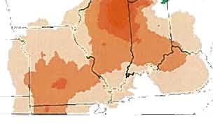
Figure
12.
Monitor-based
back
trajectory
plot
for
high
ozone
days
in
Holland,
Michigan
Note:
darker
shading
represents
higher
frequency
(e.g.,
air
is
most
likely
to
have
passed
through
areas
with
dark
orange
shading
—
I
I
.
—
—
I
0
Percent
PARTS211AND217
)
TESTIMONY
OF
JAMES
E.
STAUDT,
Ph.D.
I,
James
E.
Staudt,
have
been
retained
by
theIllinois
Environmental
ProtectionAgency
(“Illinois
EPA”)
as
an
expert
in
this
nitrogen
oxides
(“NOx”)
rulemaking
addressing
various
source
categories
and
Reasonably
Available
Control
Technology
(“RACT”).
I
have
previously
testified
regarding
this
rulemaking
in
both
pre-filedtestimony
and
in
person
on
October
14,
2008.
I
have
also
examined
the
testimony
of
witnesses
for
industries
affected
by
the
proposed
rule
during
the
hearing
on
December
9
and
10,
2008.
In
response
to
this
testimony
by
industry,
I
have
prepared
the
followingrebuttaltestimony.
Summary
of
Testimony
It
is
my
opinion
thatConocoPhillips
and
United
States
Steel
(“US
Steel”)
werenot
convincing
in
theirarguments
to
increase
the
emissions
rates
proposed
in
the
rule.In
support
of
their
argument
for
higher
emission
limits,
ConocoPhillips
cited
costs
estimated
from
Ultra
Low
NOxBurner
(“ULNB”)
projects
associatedwith
ConocoPhillips’ConsentDecree
that
are
far
above
the
costs
(about
15
to
20
times)
reported
for
similar
technology
by
numerous
independent,
publicly
available
studies.
However,
to
date,
none
of
thesupporting
information
for
these
cost
estimates
has
beenmade
available
for
examination
and
ConocoPhillips
couldnot
provide
many
important
details
on
these
estimates
when
asked
at
the
December
9
hearing.
Withregard
to
US
Steel,
information
it
provided
was
found
to
have
errors
and
contradictions
and
was
missing
key
pieces
of
information,
as
I
willdescribe
in
more
detail
in
thefollowingtestimony.
Using
more
informationthey
did
provide.
This
information
was
requested
at
the
hearing,but
has
not
yet
been
provided
(Transcript
of
December
10,
2008,
hearing,
(“12/10/08
TR”)p.
31,
lines
11-20).
Forthese
reasons
I
do
not
believe
either
ConocoPhillips
or
US
Steel
provided
convincing
information
in
support
of
theirarguments
for
higher
NOx
emission
rates.
Comments
on
ConocoPhillips
Testimony
ConocoPhillips’
argument
largely
relies
on
Mr.
Dunn’sassertion
that
the
costs
of
NOx
controls
that
could
meet
the
proposed
limits
are
well
above
the
cost
range
targeted
by
the
rule.
Mr.
Dunn
stated
that
as
a
result
of
the
proposed
emission
rates
ConocoPhillips
is
“looking
at
least
at
low
NOxburners
probablywith
FGR,
flue
gas
recirculation,
or
ultra
low
NOx
burners”
(Transcript
of
December
9,
2008,
hearing
(“12/9/08
TR”),
p.
144,
lines
5-7).
Mr.
Dunn
testified
that
the
proposed
emission
rates
are
well
above
what
is
achievable
with
ULNB
(12/9/08
TR,
p.
146,
lines
2-13;
p.
148,
lines2-21).
Mr.
Dunn
also
testifiedthat
the
proposed
rule
does
not
require
ULNB(12/9/08
TR,
p.
143,
lines
9-13).
Moreover,
according
to
the
technical
support
document
(“TSD”),
emissions
limits
are
consistent
with
thoseachievable
with
low
NOxburners,
and
as
noted
above,
Mr.
Dunncited
low
NOx
burners
as
a
possibility.
So,
facility
ownershave
moreoptions
than
just
ultra
low
NOx
burners.
Mr.
Dunn
also
admitted
that
ULNB
could
be
used
on
a
large
unit
to
allowsmaller
units
to
average
in
with
littleor
no
effort
(12/9/08
TR,
p.
148,
line
22
through
p.
149,
line
5).
So,
this
is
not
a
question
of
whether
or
not
the
emissions
rates
2
removed.
ULNB
are
reported
in
theTSD
to
cost
in
the
range
of
about
$1000/ton
of
NOx
removed
(TSD
pages
43,
64,
65).
Tn
his
pre-filed
testimony,
Mr.
Dunn
used
a
cost
estimate
of
burnersinstalled
pursuant
to
a
ConsentDecree
to
argue
that
ULNB
are
more
expensive
—
inthe
range
of
$15,000
to
$20,000/ton
of
NOx
removed
(Pre-filed
Testimony
of
David
Dunn,
p.
7-12).
However,
Mr.
Dunn
couldnot
explain
why
the
cost
effectiveness
estimate
ConocoPhillips
developed
for
ULNB
retrofits
was
so
much
higherthan
what
is
widelyreported
in
literature
from
LADCO,
USEPA,
and
others,
and
as
documented
in
theTSD
(12/9/08
TR,
p.
153,
lines
15-20).
It
is
important
to
point
out
that
a
dollar
per
ton
of
NOx
removedestimate
entails
many
assumptions
that
can
greatly
skew
the
estimate
in
one
direction
or
another.
There
are
assumptionsregarding
what
shouldbe
included
in
the
capital
cost,
the
amortization
of
that
cost
to
a
yearly
capital
charge,
what
is
assumed
as
the
initial
versus
the
final
emissions
levels,
how
and
if
overhead
shouldbe
accounted
for,
insurance
costs,
taxes,
assumptions
for
allowance
for
spare
parts,
maintenance,
the
cost
of
other
routine
maintenance
that
may
be
performed
at
the
same
time
as
the
project,
etc.
Many
of
these
are
outlined
in
USEPA’sAir
Pollution
Control
Cost
Manual
(http://www.epa.gov/ttnlcatc/products.html#cccinfo).
As
a
result,
by
adjusting
the
assumptions,
it
is
possible
to
arrive
at
a
wide
range
of
dollar
per
ton
of
NOxremoved
cost
estimates
for
any
given
project.
Because
of
this,
examination
of
the
assumptions
is
important
for
interpreting
such
a
cost
estimate.
3
in
Mr.
Dunn’s
pre-filed
testimony.
TheIllinois
EPA
attempted
to
learn
whatwould
account
for
this
difference
during
hearing,
such
as
inclusion
of
other
“routinemaintenance”
items
or
what
assumptions
were
used
to
craft
thisestimate
of
dollar
per
ton.
When
askedabout
assumptions
of
the
cost
effectiveness
estimate,
Mr.
Dunn
admitted
that
the
costestimate
included
significant
indirect
costs.
Furthermore,
he
could
not
describe
many
of
the
key
underlyingassumptions
used
to
craft
the
dollar
per
tonestimate
(12/9/08
TR,
p.
159,
lines
2-20;
p.
161,
lines
8-1
1).
The
underlying
costanalysis
has
not
beenprovided
to
the
Board
to
date.
In
addition,
due
to
claims
that
the
“detailed”
cost
estimate
is
privileged,
it
is
not
clear
whether
the
Illinois
EPA
canallow
me,
as
an
IllinoisEPAcontactor,
to
examine
and
comment
on
it
(12/9/08
TR,
p.
151,
lines
4-10;
p.
154,
lines
18-20).
ConsideringthatConocoPhillips’
cost
estimates
are
so
inconsistentwith
numerous
independent
estimates
that
have
beenwidely
published,
and
that
the
company
will
notsubject
the
data
to
public
scrutiny,
it
is
myopinion
that
the
company’s
cost
information
should
not
be
considered.The
Illinois
EPA
has
relied
on
independent
and
publicly
verifiable
estimates,
as
documented
in
theTSD,
and
this
information
demonstrates
that
the
proposed
emissions
limits
are
achievable
with
available
technology
at
a
cost
that
is
within
the
range
of
RACT.
4
available.
Moreover,
there
are
errors
and
inconsistencies
in
the
data
presented.
In
justifying
its
conclusions,
US
Steel
made
several
assertions
without
any
supporting
dataor
calculations.
Upon
examination
I
found
these
assertions
to
be
erroneous.
In
the
following
paragraphs
I
will
examine
these
assertions
as
well
as
errors
or
inconsistencies
in
calculations
that
were
presented.
Assertions
by
US
Steel
Found
to
be
Erroneous
US
Steel’s
consultant,
Mr.
Stapper,
ruled
outlow
NOx
burners
and
selective
non-
catalytic
reduction
(“SNCR”)
as
viable
NOx
control
options,
although
he
made
no
effort
to
contactsuppliers
of
these
technologies
to
determine
the
suitability
of
these
technologies
(12/10/08
TR,
p.
39,
line
16
through
p.
40,
line
3;
p.
48,
line
19
through
p.
49,
line
17).
Despite
having
no
information
from
burner
suppliers,
Mr.
Stapper
testified
thatthere
were
no
low
NOx
burnersthat
wouldapply
to
the
multi-fuel
application
of
Boilers
11
and
12
(12/10/08
TR,
p.
19-
20,
39).
Moreover,
he
testified
thatburners
would
cause
dangerous
conditions
that
could
result
in
furnace
explosions
(12/10/08
TR,
p.
20,
lines
14-17).
These
assertions,
as
will
be
demonstrated,
are
incorrect.
While
there
are
challenges
to
cofiring
low
BTU
fuels
such
as
Blast
Furnace
Gas
with
Natural
Gas
or
other
higher
BTU
fuels,
this
canand
has
been
done.
Mr.
Stapper
relied
solely
on
his
own
experience
withoutconsulting
any
burner
suppliers
or
boiler
manufacturers.
Mr.
Stapper
made
it
clear
that
it
is
URS’snormalpractice
not
to
contact
technology
suppliers
for
information
(12/10/08
TR,
p.
49,
lines
8-17).
As
a
result,
it
is
uncertain
whether
Mr.
Stapper
is
5
have
since
contacted
burner
suppliers
to
evaluate
Mr.
Stapper’s
assertions.
In
contrast
to
Mr.
Stapper’s
testimony,BloomEngineering,
North
American
Burner,
Coenand
Hamworthy
Peabody,
all
reputable
burner
suppliers,have
stated
that
they
supply
burners
that
are
capable
of
safely
reducing
the
NOx
from
US
Steel’s
boilersfor
thefuel
conditions
that
US
Steel
projected.
As
for
specificemissions
rates,
they
could
not
confirmemission
rates
without
a
more
careful
examination
of
the
boiler.
However,
some
of
them
provided
ranges
based
upon
the
burners
that
they
offer.
Information
from
these
companies
is
provided
in
Exhibit
1
and
as
attachments
to
this
testimony.
These
companies
haveexperience
in
supplying
such
burners
on
other
steel
mill
and
mixed
fuel
applications.
In
fact,
multi-fuel
burners
are
not
as
rare
as
Mr.
Stapper
asserted
in
his
testimony
and
are
commonly
used
in
the
steel
industry
as
well
as
in
the
refining
industry.
Refinery
coking
processes
can
also
produce
low
BTU
gases
that
are
fired
at
the
refinery.
According
to
the
Handbook
of
Petroleum
Processing,’
edited
by
D.
S.
J.
Jones
and
Peter
R.
Pujado,
Exxon
Mobil’s
Flexicoke
processproduces
a
low
BTU
gas
with
a
lower
heating
value
of
127
Btu/SCF
that
is
similar
to
the
heating
value
of
Blast
Furnace
Gas.
This
gas
is
fired
at
the
refinery
once
sulfurbearingcompounds
are
cleaned
from
the
gas.
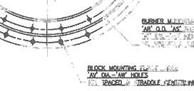
Mr.
Stapperfurther
testified
thatinstalling
a
circular
low
NOx
burner
on
the
tangentially
fired
(also
referred
to
as
“corner
fired”)
Boiler
number
11
would
require
complete
reconstruction
‘http://books.google.com/books?id=D6pb
1YnOvYoC&dg=Handbook+of+Petro1eum+Processing&printsec=frontcov
er&soceb1&otsXW2zZa1
Qct&sig=nKh8rkyzFJmKLTXO
WZ7cmGB8_s&hl=en&sa=X&oi=book
result&res
num8&ctresult#PPA453
,M
1
6
conducted
a
simple
Google
search
for
“Tangential
Low
NOx
Burners”
(see
http://www.coen.com/i
html/pdf/TFireLowNoxOilRef.pdf,
which
was
the
first
item
to
come
up
on
such
a
search).
Coen,
as
well
as
other
companies,
sell
low
NOxburners
or
burner
modifications
for
tangentially
fired
boilersthat
fire
gas.
These
are
burners
that
are
installed
in
the
existingcorner
burner
areaand
do
notrequire
reconstruction
of
the
boiler.
In
response
to
my
request
for
information,
the
Coen
Company
stated
that
they
couldsupply
low
NOxburners
for
this
application
(Boilers
11
and
12).
Mr.
Stapper
also
testifiedthat
there
would
be
risks
of
furnace
explosions
with
the
use
of
Low
NOxburners
(12/10/08
TR,
p.
20,
lines
11-17)
andstated
that
“There
are
no
low
NOx
burners
that
could
safely
be
installed
on
boiler
12
to
burn
blast
furnace
gas
and
Cokeoven
gas”
(12/10/08
TR,
p.
39,
lines
13-15).
He
did
not
provide
any
data
or
calculations
to
support
this
assertion
and
didnot
contact
any
burner
suppliers
to
check
onthis.
(12/10/08
TR,
p.
39,
lines
16-
20)
There
is
always
a
risk
of
a
boiler
explosion,
regardless
of
the
burner
type
or
fuel.
Because
a
boiler
explosion
is
such
a
catastrophic
event,
under
the
National
Fire
Protection
Association
PA)
codes,
all
boilers
must
be
equipped
withinstrumentation
and
controls
to
avoid
such
events,
which
is
why
these
events
are,
thankfully,
so
rare.
In
contrast
to
Mr.Stapper’
s
assertion
that
such
burners
are
dangerous,
which
he
didnotsupport
with
any
information
from
technology
suppliers
or
with
any
engineering
calculations,
four
reputable
burner
suppliers
have
stated
that
they
cansupply
low
NOxburners
for
this
application.
7
suppliers
of
this
technology
haveshown
in
the
hundreds
of
industrialinstallations
that
the
technology
is
available
and
works
in
multi-fuelindustrial
boiler
applications,
as
well
as
a
wide
array
of
other
applications,
which
is
supported
by
theTSD
and
supporting
documents
inthe
original
submittal.
Mr.
Stapper
admitted
that
he
did
notcontact
a
single
supplier
of
SNCR
technology
for
technical
input,
and
that
URS
has
never
supplied
an
SNCRsystem
(12/10/08
TR,
p.
47,
line20
through
p.
48,
line
4).
As
a
result,
his
testimony
regarding
SNCR,
likehis
testimony
regarding
lowNOx
burners,
amounts
only
to
hisassertions
without
adequate
supporting
data.
In
Mr.
Stapper’s
hearing
testimony,
he
discussed
the
John
Zink
RapidMix
Burner
(12/10/08
TR,
p.
51,
line
6
through
p.
53,
line
17).
He
testified
that
the
Rapid
Mix
Burner
achieves
0.01
lb/MMBtu
and
that
it
“works
only
in
a
very
narrow
niche
of
industrial
boiler
applications”
(12/10/08
TR,
p.
52,
line
8-10).
However,
as
he
stated,this
technology
is
not
required
by
the
rule
(12/10/08
TR,
p.
54,
line
11-12).
Moreover,
theIllinois
EPA’s
proposed
limits
for
boilers
are
eijiht
times
the
emission
ratethat
Mr.
Stapper
testified
the
Rapid
Mix
Burner
is
capable
of.
Therefore,the
Rapid
Mix
Burner,
or
otherultra
low
NOxburners
from
other
manufacturers,may
be
used
to
complywith
the
proposed
rule
where
the
owner
deems
this
the
appropriate
technology.
However,
because
the
proposed
limits
are
far
in
excess
of
whatultra
low
NOx
burners
are
capable
of,
facility
ownershave
many
moreoptions
at
their
disposal
than
the
Rapid
Mix
Burner
to
achievethe
proposed
emission
rates.
8
US
Steel
did
not
provideback
up
for
the
assumptions
that
underlie
its
recommended
emission
rates
for
Boilers
11
and
12
that
are
shown
in
Exhibit
A
to
Mr.
Siebenberger’s
pre-filed
testimony.
US
Steeldid
not
provide
any
test
data
or
other
supporting
information.Calculations
werenot
shown
to
explainthe
largedifference
between
the
presumed
emission
rate
for
coke
oven
gas
(COG)
versusthat
of
natural
gas
(NG).
Supporting
information
for
Exhibit
A
was
requested,but
to
date
has
not
yet
been
provided.
(12/10/08
TR,
p.
28,
line
22
-
p.
29
line
7)
The
principal
reason
coke
oven
gashas
higherNOx
emissions
thannatural
gas
is
the
hydrogen
cyanide
(“HCN”)
present
in
the
gas
(Pre-filed
Testimony
of
Larry
Siebenberger,
p.
5),
shown
on
the
gas
analysis
provided
by
US
Steel
to
the
Illinois
EPA
as
0.185%
(moleweighted)
without
the
COG
scrubber
and
0.0
13%
(mole
weighted)
with
the
COG
scrubber.
2
However,
even
if
itis
conservativelyassumed
that
100%
of
the
nitrogen
in
the
HCN
of
the
COG
is
oxidized
to
form
NOx,
it
wouldnot
explain
the
increased
NOx
TIRS
assumed
for
scrubbed
COG
over
NG.
URS
assumed
in
Exhibit
A
to
Mr.
Siebenberger’s
pre-filedtestimonythatwith
the
COG
scrubber
in
service,
NG
produces
emissions
of
0.084
lb/MMBtu
and
COG
produces
0.144
lb/MMBtu,
a
difference
of
0.06
lb/MMBtu.
No
basis
for
theseemission
estimates,such
as
test
2
Fuelanalysis
provided
by
US
Steel
to
the
Illinois
EPAshows
that,on
a
mole
weight
basis,
COG
has
52%
hydrogen,
26%
methane,
5%
CO,
2%
ethylene
and
most
of
the
rest
are
incombustibles
(nitrogen,
water,
CO
2
).
Pure
hydrogen
would
potentially
increase
the
flame
temperature
and
the
NOx
relative
to
natural
gas.
But
for
COG,
which
contains
significant
amounts
of
moisture
and
non-combustibles,
and
only
52%
hydrogen,
we
would
not
expect
an
increase
in
thermal
or
promptNOx
generation
over
natural
gas,
likely
even
a
decrease.
This
is
supported
by
data
generated
by
Waibel
and
others
on
NOx
generationfrom
gas
mixtures.
ADVANCED
BURNER
TECHNOLOGY
FOR
STRiNGENTNOxREGULATIONS,
R.
T.
WAIBEL,
PHD
.,
D.
N.
PRICE
AND
P.
S
.
TISH,
M.L.
HALPR[N,PRESENTED
AT
THE
AMERICAN
PETROLEUM
INSTITUTEMIDYEAR
REFINING
MEETING
JOINTMEETING
OF
THE
SUBCOMMITfEE
ON
HEAT
TRANSFER
EQUIPMENT,
ORLANDO,
FL,
MAY
8,
1990,
www.johnzink.com/elibraiy/DownloadFile.
aspx?fileguid=8e219961-ec78-4]
Of-bb6754dd87]d2d4
7
9
COG
fuel
analysis,
I
estimate
that
if
all
of
the
nitrogen
in
the
HCN
in
the
cleaned
COG
oxidized
to
NOx,
this
would
increase
NOx
by
only
about
0.03
lb/MMBtu
—
half
that
estimated
by
URS
for
US
Steel
(see
Table
1,
attached).
Furthermore,
in
actual
practice,
significantly
less
than
100%
of
the
fuel
bound
nitrogen
actually
gets
converted
to
NOx,
particularly
if
low
NOxburners
or
other
combustion
controls
are
used.
So,
the
difference
in
theemission
rate
should
be
less
than
the
0.03
lb/MMBtucontributed
by
100%
HCN
oxidation.
Additionally,
IJRS’s
estimate
in
Exhibit
A
of
Mr.
Siebenberger’s
pre-filed
testimony
shows
a
difference
between
NG
and
COG
without
the
scrubber
to
be
0.252
lb/MMBtu
(0.336-0.084
lb/MMBtu),
roughly
59%
of
what
is
theoretically
predicted
for
100%
conversion
of
fuel
bound
nitrogen
to
NOx
(0.252/0.422
-
see
Table
1
for
estimate
of
fuel
bound
NOx
from
unscrubbed
COG).
It
appears
that
IJRS
has
overestimated
theemissions
level
of
scrubbed
COG.
Therefore,
URS
may
have
made
a
mistake
in
its
calculations
for
NOx
from
the
various
gases,
which
it
has
not
yet
provided
for
the
Illinois
EPA
or
the
Board
to
review.
Mr.
Siebenberger
also
testified
that
there
is
an
error
in
Exhibit
A
of
his
pre-filed
testimony.
Exhibit
A
of
his
pre-filed
testimony
does
not
have
the
correct
mix
of
gases
for
conditions
where
the
blast
furnace
is
out
of
service
(12/10/08
TR,
p.
28,
line
17-21).
Instead
of
firing
60%
COG
and
40%
NGwhen
the
BlastFurnace
is
not
in
service
as
stated
on
page
2
of
Exhibit
A,
the
boilers
would
fire
60%
NG
and
40%
COG.
Since
this
error
overestimates
the
3
10
Mr.
Siebenberger’
s
pre-filed
testimony
using
the
assumptionsthat
are
shownin
that
exhibit
and
his
testimony.
I
arrived
at
different
results
for
both
tons
of
NOx
emitted
and
the
emission
rate.
The
Controlled
case
calculations
were
performed
two
ways:
one
assuming
60%
COG
and
40%
NG
during
the
Furnace
Down
period
(see
Table
2,
attached),
andone
assuming
40%
COG
and
60%
NGduring
the
Furnace
Down
period
(see
Table
3,
attached).
Neither
case
produced
results
that
corresponded
with
the
annual
NOx
emissions
rate
or
total
NOx
shown
in
Exhibit
A.
I
was
able
to
reproduce
the
“Base
Case”
calculations
for
emissions
(see
Table
4,
attached),
soit
appears
that
I
am
using
the
same
approach
as
used
by
US
Steelin
Exhibit
A.
Therefore,while
theIllinois
EPA
is
notstating
that
it
agrees
with
the
assumptions
of
US
Steel’s
analysis,
the
assumptions
that
US
Steel
uses
do
not
appear
to
produce
the
results
shown
in
Exhibit
A
for
the
controlled
case.
The
rate
that
US
Steel
requests
of
0.113
lb/MMBtu
that
was
developed
from
these
assumptions
does
correspondwith
the
estimated
OzoneSeason
emission
rate
using
the
original
assumptions
stated
in
Mr.
Siebenberger’
s
pre-filed
testimony.
However,
this
higher
NOx
emission
rate
for
the
OzoneSeason
is
an
anomaly
of
the
assumption
to
shut
down
the
COG
scrubberduringtheOzone
Season
and
the
fact
that
he
overstated
theamount
of
COG
fired
when
BFG
was
unavailable.
In
light
of
the
importance
of
keepingNOx
emissions
low
during
the
Ozone
Season,
it
would
certainly
make
more
sense
to
have
the
COG
scrubber
serviced
at
other
times.
The
annual
totalNOxemissions
and
therate
that
I
calculated
in
attempting
to
reproduced
11
because
the
assumptions
are
incorrect.
As
Mr.
Siebenberger
statedon
page
4
of
his
pre-filed
testimony,
Boilers
1-10
will
be
shut
down
as
part
of
the
Cogen
project
improvement.
This
will
causemore
COG
to
be
burned
in
Boilers
11
and
12.
So,
the
historical
baseline
NOxemissions
for
Boilers
11
and
12
are
not
as
great
as
assumed
in
the
Baseline
calculation
for
Exhibit
A.
More
importantly,
US
Steel
did
not
take
into
account
in
their
Baseline
calculation
thefact
that
the
COG
desulfurization
system
would
be
in
operation.
US
Steel
should
certainly
have
assumed
the
reduced
COG
NOx
level
for
the
COG
resulting
from
the
desulfurization
system,
because
this
is
definitely
going
to
be
thecase
regardless
of
the
proposed
NOx
RACT
rule.
Since
US
Steel
assumed
in
its
Baseline
the
higher
NOx
levels
for
COG
withoutdesulfurization
at
all
times,
its
estimate
of
the
Baseline
is
grossly
overstated
and
the
reduction
in
emissionsshown
on
Exhibit
A
is
therefore
grossly
overstated.
Moreover,
the
COG
usagewill
likely
be
less
fortheboilers
than
assumed
in
Exhibit
A
due
to
limitations
on
availability
of
COG.
According
to
a
January
8,
2009,
e-mail
sentfrom
Mr.
Siebenberger
to
Mr.
Kaleel,
the
available
COG
is
3,830,400
million
Btu/yr.
US
Steel
did
not
provide
information
on
how
much
COG
is
fired
in
the
reheat
furnaces,
except
that
its
emission
rate
for
the
reheat
furnaceswas
based
on
the
“maximum
combusted
blend
of
desulfurized
coke
oven
gas
and
non-desulfurized
cokeoven
gas.”The
reheat
furnaces
have
the
heat
input
capacity
to
accept
100%
of
the
COG.
If
US
Steel
opted
to
use
all
of
the
available
COG
in
the
reheat
furnaces,
then
none
of
it
would
be
available
to
boilers
11
and
12.
If
it
is
assumed
that
the
reheat
12
appears
to
havebeen
assumed
by
US
Steelin
developing
Exhibit
A
of
Mr.
Siebenberger’s
pre
filed
testimony.
This
is
a
significant
overestimate
of
theamount
of
COG
that
is
actually
available,
which
results
in
a
significant
overestimate
of
the
amount
of
NOxgenerated
from
this
fuel.
It
is
likely
that
the“excess”
COG
wouldhave
to
be
replacedwith
natural
gas,
which
would
further
reduce
emissions,
since
natural
gas
has
a
lower
NOx
content
than
COG.
As
a
result,
US
Steel
has
overstated
the
controlled
NOx
emission
rate.
I
re-estimated
the
rateusing
US
Steel’s
assumptions,
but
corrected
per
Mr.
Siebenberger’s
testimony
and
corrected
to
account
for
the
actual
availability
of
COG
and
40%
COG
firing
in
the
reheat
furnaces
(making
COG
firing
in
the
boilers
less
than
40%).
The
results
are
shown
in
Table
6,
attached.
As
shown,
using
US
Steel’s
estimates
for
emissions
rates,
which
as
discussed
earlier
are
probably
high
for
COG,
I
arrive
at
an
annual
rate
of
0.091
lb/MMBtu
—
which
is
less
than
the
rate
recommended
by
US
Steel.
Correcting
the
COG
NOx
rate
for
the
maximum
amount
of
fuel
NOx
results
in
an
annualrate
of
0.084
lb/MMBtu
—
very
close
to
the
Illinois
EPA’s
proposed
rate
(see
Table
7,
attached).
It
is
possible
that
all
of
the
COG
could
be
used
in
the
reheat
furnaces,
leaving
none
for
the
boilers,
sincethe
available
COG
has
roughly
53%
of
the
heat
input
available
for
the
reheat
furnaces.
As
shown
in
Table
8,
attached,
if
all
of
the
COG
is
fired
in
the
reheat
furnaces,
leavingnone
for
Boilers
11
and
12,
the
annualemission
rate
is
0.075
lb/MMBtu,
which
is
less
than
the
proposed
rule.
13
that
US
Steel
provided
in
its
fuel
analysis
and
testimony
show
inconsistencies,
and
no
back
up
calculations
or
test
datawereprovided.
I
have
shown,
by
reproducing
US
Steel’scalculations,
that
US
Steel
apparentlymade
severalerrors
in
assumptions
and
in
calculations.
Therefore,
US
Steel’s
emissionestimates
for
Boilers
11
and
12
should
be
regarded
with
caution,
and
the
Board
should
not
consider
them
until
such
time
as
more
reliable
information
is
available
from
US
Steel.
US
Steel
claims
that
its
approach
for
NOx
control
on
Boilers
11
and
12
was
the
result
of
an
optimization
study.
This
study
was
requested
for
examination
at
hearing
(12/10/08
TR,
p.
41,
lines
12-23).To
date,
this
has
not
yet
beenproduced
for
the
Illinois
EPA
or
Board
to
examine.
US
Steel’s
emissionrates
for
the
reheat
furnacewere
also
providedwithout
any
supporting
backup.The
IllinoisEPA
requested
this
additional
information
at
thehearings,
On
page
7
of
his
pre-filedtestimony,
Mr.
Siebenberger
stated
that
the
limit
was
“based
on
the
burner
manufacturer’s
warranty
andthe
maximum
combustedblend
of
desulfurized
cokeoven
gas
and
non-desulfurized
coke
oven
gas
(during
desulfurized
maintenance
outage)
with
natural
gas.”
Exhibit
A
states
that
these
are
developed
by
BloomManufacturing
andMr.
Siebenberger
testified
that
he
believedthat
they
were
guaranteed
values.
(12/10/08
TR,
p.
34,
lines20-23)
The
Illinois
EPA
has
asked
to
see
the
technical
proposal
from
Bloom
and
URS’s
supporting
calculations.
Once
we
receive
that
information,
it
will
enable
us
to
examine
the
emissions
rate
requested
by
US
Steel
forthe
reheat
furnaces
and
also
examinehow
much
COGwillactually
be
available
foruse
in
Boilers
11
and
12.
14
)¸
information.
Further,
Mr.
Stapper
made
numerous
assertions,
without
supporting
data,
which
in
some
cases
appear
to
have
been
intended
to
shock
the
Board
rather
than
to
informthem
(especially
the
testimony
regarding
furnace
explosions).
There
also
appear
to
be
calculation
errors
in
their
estimates
of
emissions,
and
there
are
errors
in
assumptions.Calculations
were
found
to
be
inconsistent
or
inaccurate,
and
no
back
up
was
provided
in
support
of
estimates
of
NOx
emission
rates.
It
appears
that
US
Steel
expects
the
Board
to
take
theseestimates
on
faith.
As
the
Illinois
EPA
has
repeatedly
stated,
it
does
not
considerRACT
any
particular
technology,
but
an
emission
ratethat
is
achievable
at
a
reasonable
cost.
The
emissions
rates
that
the
Illinois
EPA
has
proposed
for
gas-firedfacilities
are
achievable
at
a
reasonable
costusing
technologies
such
as
low
NOx
burners
or
other
combustion
controls.
This
is
supported
by
numerousindependent
studies
that
are
publicly
available
and
have
been
cited
in
the
TSD.
15
I’m
not
sure
how
the
Blast
Furnace
Gas
is
currently
injected
with
existing
burners,
but
Coen
has
experience
supplying
low
NOx
burner
designs
firing
Natural
Gas,
Coke
Oven
Gas
and
Blast
Furnace
Gas.
We
use
a
“Low
Btu
Gas
Scroll,”
which
is
an
integral
part
of
the
burner,
to
fire
the
Blast
Furnace
Gas.
In
this
case,
the
Natural
Gas
and
Coke
Oven
Gas
are
each
fired
through
their
own
set
of
gas
injectors,
but
the
Blast
Furnace
Gas,
since
it
is
injected
directly
into
the
burner
through
a
scroll,
acts
like
FGR
(flue
gas
recirculation)
to
reduce
the
flame
temperature
and
corresponding
NOx
emissions.
Your
Coke
Oven
Gas
analysisreveals
a
relatively
low
HCN
level.
In
other
words,
the
NOx
contribution
from
this
fuel
bound
nitrogen
is
refreshingly
small.
We
would
need
a
host
of
details
regarding
the
boilers,
firing
rates,number
of
burners
per
boiler,
burner
spacing,
etc.,
but
assuming
ambient
combustion
air,
I
would
guess
our
burners
would
be
in
the
range
of
0.03
to
0.05
Ib/MMBtu
NOx
when
firing
all
three
fuels
at
once
(normal
operation).
However,
when
the
Blast
Furnace
Gas
is
down,
you
would
have
to
run
with
some
FGR
to
meet
the
same
level
of
NOx
emissions
that
you
would
haveunder
normal
operation.
If
you
have
any
questions,
please
call.
If
you
can
provide
moredetails,
we
can
take
a
closer
look
at
each
application.
Best
regards,
Scott
Krahn
Application
Engineer
Industrial
Retrofits
Group
Coen
Company,
Inc.
1510
TanforanAvenue,
Woodland,
CA
95776
USA
Tel:
1
(530)
668-2100
Fax:
1
(530)668-2171
Direct:
1
(530)
668-2119
http://www.coen.com
16
Please
expand
on
your
definition
of
“low
NOx”
as
that
means
different
things
to
different
people.
What
levels
are
you
striving
for
on
each
firing
scenario?
Regards,
Scott
Ingram
Regional
Sales
Manager
Hamworthy
Peabody
Combustion
-
Global
Solutions,
Local
Delivery
Hamworthy
Peabody
Combustion
mc,
70
SheltonTechnology
Center,
Shelton,
CT
06484
Direct:
(952)
476-5972
Fax:
(952)
473-2639
Mobile:
(320)
260-5807
Email:
singrarn@hamworthy-peabody.
corn
www.hamworthy-peabody.com
Offices:
UK
(Poole
HQ,
Birmingham,
Glasgow),
USA
(Houston
TX,
Norwich
NY,
Shelton
CT)
Australia,
Brazil,
Canada,
China,
Dubai,
France,
Germany,
India,
Italy,
Japan,
S.Korea,
Mexico,
Netherlands,
Poland,Spain
This
e-mail
and
any
files
attached
to
it
are
confidential
andintended
solely
for
the
use
of
the
individual
towhom
they
are
addressed.
Any
unauthorized
use
or
re-transmission
of
this
e-mail
and
attachments
is
strictly
forbidden,
If
this
e-mail
is
received
by
anyone
other
than
the
addressee,
please
delete
it
and
any
attachments
and
notify
Hamworthy
Peabody
immediately
(Tel.
203922
1199).
17
Good
to
hear
from
you
again.
We
do
have
Ultra-
Low
NOx
technology
in
the
Magna
Flame
LE
series..
I’ve
copied
in
several
NA
key
people
so
they
have
visibility
of
your
request.
Thelean-
premix
technology
is
described
in
the
attached
bulletins.
The
concept
is
applicable
to
any
gaseous
fuel.
There’s
a
few
other
application
questions
that
we
would
need
answered(available
pressures,
BOF
and
COG
analysis,
etc)
to
set
expectations..
if
you
are
around
next
week,
I’ll
call
to
discuss.
Bill
Tracey
+
610-996-8005
biIItraceynamfg.com
From:
Jim
Staudt
[mailto
:
staudt@andovertechnology.com]
Sent:
Friday,
December
19,
200812:06
PM
To:
Bill
Tracey
Subject:
NOx
reduction
at
steel
mill
boilers
Bill,
I
am
looking
to
reduce
NOx
from
two
225
MMBtu
boilers
at
a
steel
millthat
fires
some
natural
gas,
somecoke
oven
gas,
andsome
blast
furnace
gas.
I
was
wondering
if
you
had
a
low
NOx
burner
thatcould
handle
these
different
fuels.
NormalOperation
35%
Blast
Furnace
Gas
25%
natural
gas
40%
Cokeoven
Gas
When
BlastFurnace
is
down
40%
natural
gas
60%
coke
oven
gas
Notethat
coke
oven
gas
will
be
desulfurized.
So,
it
will
usually
have
most
or
all
of
HCN
removed.
Also,
one
boiler
is
wall
fired
with
two
burners
and
theother
is
corner
fired.
18
Best
Regards,
Jim
Staudt,
Ph.D.,
CFA
office:
978-683-9599
mobile:
978-884-5510
staudt@AndoverTechnology.com
This
e-mail
contains
information
that
may
be
proprietary
and
confidential
to
Andover
TechnologyPartners
and/or
ourclients.
If
you
have
received
this
message
in
error,
please
erase
the
message,
do
not
print
it
outor
forward
it
to
others
or
share
the
information
in
anyway,and
please
notify
us
of
our
mistake.
Thank
youfor
your
cooperation.
19
Dear
Jim:
In
General
with
the
limited
information
you
have
provide
us.
Under
operating
condition
of
25%
natural
gas,
35%
Blast
Furnace
Gas,
and
45%
COG
using
a
Bloom
1030
Series
burner
on
boiler
we
predictemissions
of
approximately
0.1
l4Lbs/MM
at
nominal
capacity
of
the
burner.
This
is
not
a
guarantee.
This
prediction
would
have
to
be
confirmed
based
on
information
you
would
need
to
provide
us.
Such
informationwould
includeFuel
analysis
of
each
fuel,
Air
to
Fuel
Ratio
Control
System,
Boiler
Dimensions
including
burner
wall
dimensions
amongother
information.
I
have
attached
1030
Series
Burner
sheets.
This
only
shows
a
single
fuel
design.
Multiply
fuel
design
would
willcause
the
burner
to
get
bigger
in
size.
If
you
have
any
questions,
please
give
me
a
call.
Very
truly
yours,
Bloom
Engineering
Company,
Inc.
Michael
J.
Binni,
P.E.
Product
Manager
of
Dryer,
Incinerator
and
Boiler
Applications
PLEASE
NOTE:
The
preceding
information
may
be
confidential
or
privileged.
It
should
only
be
used
or
disseminated
for
the
purpose
of
conducting
business
with
Bloom
Engineering
Co,
Inc.
If
you
are
not
an
intended
recipient,
please
notify
the
sender
by
replying
to
this
message
orcalling
(412)
653-3500
and
then
delete
the
information
from
your
system.
Thank
you
for
your
cooperation.
20
Table 1. Calculation
of fuel NOx from scrubbed and unscnbbed
COG
_______
mole %
Mole % times MW
WI %
MW
unscrubbed scrubbed unscrubbed
scrubbed unscrubbed scrubbed
H2S
34
0.603
0.037
0.20502
0,01258
1.783%
0.112%
C02
44
1.421
0.709
0.62524
0.31196
5.437%
2.776%
C02
28
4.975
4.950
1.393
1.386
12.114%
12.333%
as N
fuel bound N lb/MMBIu
Cs
60
0.005
0.002
0.003
0.0012
0.026%
0.011%
unscrubbed scrubbed
unscrubbeci
scrubbed
HCN
27
0.185
0.013
0.04995
0.00351
0.434%
0.031%
0.225%
0.016%
0.128
0.009
0.422
502
64
0.000
0.000
0
0
0.000%
0.00034
CS2
76
0.010
0.010
0.0076
0.0076
0.066%
0.068%
Merc
48
0.000
0.000
0
0
0.000%
0.000%
HHV
NH3
17
0.000
0.000
0
0
0.000%
0.000%
with scrubber
CH4
16
26.295
26.163
4.2072 4.18608
36.588%
37.248%
Btu/scf
Btu/Ibrnole
Ethylene
28
2.132
2.121
0.59696 0.59388
5.191%
5.284%
524
199,120
Ethane
30
0.622
0.619
0.1866
0.1857
1.623%
1.652%
without_scrubber
Propane
44
0.177
0.176
0.07788 0.07744
0.677%
0.689%
Btu/scf
Btu/lbrnole
Isobutane
58
0.089
0.088
0.05162 0.05104
0.449%
0.454%
531
201,780
n Butane
58
0.089
0.088
0.05162 0.05104
0.449%
0.454%
Isocentane
72
0.089
0.088
0.06408 0.06336
0.557%
0.564%
n Pentane
72
0.089
0.088
0.06408 0.06336
0.557%
0.564%
Benzene
78
0.523
0.519
0.40794
0.40482
3.548%
3.602%
Heavies
86
0.042
0.042
0.03612 0.03612
0.314%
0.321%
H2S
2
52.145
51.885
1.0429
1.0377
9.070%
9.234%
Nitrogen
28
4.962
4.938
1.38936
1.38264
12.082%
12.303%
02
32
0.283
0.281
0.09056 0.08992
0.788%
0.800%
H20
18
5.268
7.180
0.94824
1.2924
8.246%
11.500%
otal
100.00
100.00
11.499
11.238
Note: Mole % and HHV data provided by US Steel toiL EPA
21
TotalAnnual
HI
40%
heat
input
for
COG
Total
available
COG
7,169,150
2,867,660
3,830,400
million
BTU/yr
million
BTU/yr
million
Btu/yr
Total
Boiler
COG
heat
in
(based
on
Exhibit
A)
60%
when
BF
down
1,452,384
million
Btu/yr
40%
when
BF
down
1,390,176
million
Btu/yr
Shortfall
60%
when
BF
down
489,644
million
Btu/yr
40%
when
BF
down
427,436
million
Btu/yr
Balance
available
to
962,740
million
Btu/yr
from
Siebenberger
e-mail
25
153
113
Total
Days
in
Period
Total
Days
Operating
in
Pen
d
days
293
Fuel
Mit
65%
0%
35%
100%
Blended
NOx
Rate
rinual
Heat
Ir
(MMBtu
3.164.40C
NOtRate
(lb/MMBtu)
0.08’l
0.144
0.0299
0.06469
Heat
In
(MMBTU)
2,0
56,860
0
1,107,540
3,164,400
NOx
Tons
CapacityFactor
100%
NO
COG
BFG
otal
Norma
Dpi
ration
86.4
0.0
15.9
102.3
NO
COG
BFG
Total
C
40
0%
0%
zone
Season
Heat
In
(MMBtu)
172,800
NOtRate
(IbfMMBtu)
0.084
0.144
0.0288
0.084
-leat
In
MM
BTU)
172.800
0
0
172,800
tOx
Tons
7.t
0.c
0,(
7.
35.00
days
COO
Rate
nnual
b/MMB0u
b/MMBtu
trillion
Btu
tons
lb/MM
Btu
lb/MM
Btu
million
Btu
tons
35.00
days
COO
Rate
a
COG
Scrubber
Mi
Ii
—
Delta
in
COO
Rate
Heat
In
NOx
delta
0.34
0.19
151,200
14.5
C
Delta
in
COG
Heat
In
NOn
delta
zone
Season
0.34
0.19
151,200
14.5
Total
NOx
Total
Heat
In
NOx
Rate
Total
mud
129.9
3,475,440
0.075
terra
millIon
Btu
lb/MMBtu
or
P
nod
C
rotal
NOx
rotal
Heat
In
NOt
Rate
I
i
l
—
I
Total
NGIn
2,367,900
million
Btu
Total
NG
In
966,060
million
Btu
Total
COG
In
0
million
Btu
Total
COG
In
0
million
Btu
Total
BFGIn
1,107,540
million
Btu
Total
BFG
In
427.140
million
Btu
zone
Season
61.2
1,393,200
0.088
tons
million
Btu
lb/MMBtu
365
293
C
Capacity
Factor
zone
Season
100%
deya
Heat
In
(MMBtu)
113
1,220,400
Fuel
Mix
NOt
Rate
llbfMMBtu)
Blast
65%
Heat
In
MMBTU)
Capacity
Factor
0%
0.084
nnual
35%
NOt
Tons
40%
days
0.144
793,260
100%
Heat
Ii,
(MMBtu
0.0288
0
33.t
Blended
NOn
72
427,140
0.0
311,04C
0.06468
NO
1,220,400
6.
Fuel
Mix
urnace
Down
time
(no
BFG
available)
COG
39.f
NOtRate
(lb/MMBSu)
BFG
Capacity
Factor
Coast
otal
Heat
In
(MMBTU)
0.084
Q9.
40%
days
0%
SlOt
Tons
311,040
0.144
100%
0.0289
13.1
0
Blended
NOn
Rate
NO
0
0.0
Fuel
Mix
0.084
311,040
COO
0.0
BFG
100%
13.1
Total
100%
Blended
NOx
28
CoenCase
Study
—
tangential
low
NOx
burner
Link
to
Handbook
for
Petroleum
Processing:
http
://books.google.comlbooks?idr=D6pb
1
YnOvYoC&dg=Handbook+of+Petroleum+Processing
&printsecfrontcover&source=bl&ots=XW2zZa1
Qct&sig=nKh8rkyzFJmKLTXOWZ7cmGB8
s&hl=en&sa=X&oi=bookresult&resnum=8
&ct=result#PPA453
,M
1
29
CAPABI
LITI
ES
Short,
compact,
clear
andbushy
flame
Suitable
for
rich
gases
10%to
300%
excess
air
through
burner
with
-
rich
gaseous
fuels
Additional
excess
air
may
be
introduced
-
down-stream
of
burner’s
port
Operates
with
moderate
air
and
fuel
pressures
Standard
design
suitable
for
furnace
pressure
of
-1”
WC
to
+5”
WC
Special
designs
available
for
other
furnace
conditions
FEATURES
Rugged
fabricatedconstruction
Flame
stabilization
with
all
refractory
or
refractory
faced
fabricated
plate
and
tube
baffle
Baffle
shields
burner
internals
from
flame
convection
and
chamber
radiation
Designed
forcold
air
or
preheated
air
to
600°F
(315°C)
with
external
insulation
of
theburner
Suitable
for
high
chamber
operating
temperature
CONTROL
Metered
flow
Linked
values
Fuel
modulation
only
FLAME
MONITORING
U.V.
Detector
OPTIONS
Air
Heaters
ThermalOxidizers
Dryers
Kilns
Boilers
Others
BURNER
IGNITION
Pilot
only
FUEL
CAPABILITIES
Natural
Gas
LPG
Mixed
Gases
Burner
block/tile
can
be
supplied
LowBtu
gas
designs
Designs
are
available
for
windbox
installations
CAUTION:
Theimproper
use
of
combustion
equipmentcan
result
in
a
condition
hazardous
to
peopleand
property.
Users
are
urged
to
comply
with
National
Safety
Standards
and/or
Insurance
Underwriters
recommendations
JLJffP1TI4
APPLICATIONS
-1
AIR
FLOW
AND
FLAME
DIMENSIONS
Air
Flow
1000
SCFH
at
100°F
Flame
Flame
Pilot
3
Catalog
Nm
3
Ihr
x
1000
@
38°
C
Length
2
Diameter
2
Part
No.
4”
WC
10
mBar
8”
WC
20
mBar
ft
mm
ft
mm
020A
235
6.35
333
9.00
10
3048
4.0
1219
2300-010
020B
300
8.00
4251
11.50
11
3353
4.0
1219
2300-010
025A
375
1010
531
1435
13
3962
45
1372
2300010
025B
469
12.70
6641
18.00
16
4877
5.0
1524
2300-010
031A
563
1520
797
2150
18
5486
55
1676
2300030
031B
705
19.00
9971
27.00
20
6096
6.0
1829
2300-030
037A
845
22.80
1195
32.30
22
6706
6.5
1981
2300-030
037B
1030
27.80
14601
39.50
24
7315
7.0
2134
2300-030
046A
1268
3430
1793
4850
27
8230
75
2286
2300030
046B
1550
42.00
21901
59.00
32
9754
8.0
2438
2300-030
057A
1878
5075
2655
7200
33
10058
85
2591
2300030
057B
2347
63.40
33201
90.00
36
10973
9.0
2743
2300-030
070A
2817
7600
3983
1075
40
12192
100
3048
2300030
070B
3521
95.00
49791
134.5
44
13411
10.5
3200
2300-030
1
Do
not
exceed
this
maximum
air
capacity
rating.
2
Flame
dimensions
are
for
10%
excess
air.
Flame
size
decreases
with
increasing
excess
air.
Contact
Bloom
for
information
at
other
conditions.
2300-O10
Air
=
4,000
scfh(108
Nm
3
/hr)
@
8”
we
(20
mBar)
Gas
=
560
scfh
(13.5
Nm
3
/hr)
@
8”
we
(20
mBar)
2300-030
Air
=
12,000
scfh
(325
Nm
3
/hr)
10”
we
(25
mBar)
Gas
=
1,500scfh
(40
Nm
3
/hr)
c
14”
we
(35
mBar)
CAUTION:
Theimproper
use
of
combustion
equipment
can
result
in
a
condition
hazardous
to
peopleand
property.
Users
are
urged
to
comply
with
National
Safety
Standards
and/or
Insurance
Underwriters
recommendations
2
9/21/2005
GENERAL
DIMENSIONS
—
020-031
HOLES
4
+
qH—
——______
-
8
4
4
—
A!
‘AJ<’SPc5DL=MI’
At’
‘AN’
NOTE:
GENERAL
DIMENSION
INFORMATION.
SEE
BLOOM
REPRESENTATIVE
FOR
CERTIFIEDDIMENSIONSFOR
CONSTRUCTION.
CAUTION:
Theimproper
use
of
combustion
equipmentcan
result
in
a
condition
hazardous
to
peopleand
property.
Users
are
urged
to
comply
with
National
Safety
Standards
and/or
Insurance
Underwriters
recommendations
3
9/21/2005
GENERAL
DIMENSIONS
—
020-031
Catalog
No.
A
B
C
0
E
F
G
H
J
K
L
M
N
P
R
S
T
U
V
W
X
Y
Z
1
030
020
2214
837.519.0018.1166
0536.5
28
39.042.0’175.0(1.7f6.5
1
Y
2
.75.25
.S
3
559
356
203
953
229470406
15
521
927
711
991
106
432
635
44
165
25
13
19
6
13
76
025
30
16
8
46.00
10.00
22.0
20
6
25.5
44.5
36
47.0
50.0
21
27.50
2.25
6.5
3
Y2
.75.25
.5
4
762406203
1168
254
559508
152
648
1130
914
11941270
533699
5716576
13
19
6
13
102
031
36
20
8
58.2112.727.1
24
6
31.1
49.5
42
52!.5
24
11.38
?.21
6.5
3
11%
.75.25
.5
4
914
508
203
1480
324
699610
152
787
12571067
1334
141(
61079757
165
76
32
19
6
13
102
nches
in
black
and
mm
in
b
ue
Catalog
Nom.
Cap
No.
AAABACADAEAFAGAHAJAKALAMANAPAR
ASATAUAVAW
RichFuels
1030-
mmbtulhr
020
.25
.38
26.5
13
A
1.1
16.f
18.5
.1
2
.2
8.50
.56
2036
32
.88
16
1.13
18
32
6
10
673
105102
105
419470
105
51
108
216
14
508
914
813
22
406
29
457
025
.25
.38
34.54.38
6
1.00
24.0
20.5
3.75
3
3.7511.25
.56
26
44
40
.88
20
1.13
28
50
6
10
876
111
152
102
610
521
95
76
95
286
14
660
1118
101622
508
29
711
031
.2
8
40.5
3.88
‘8
3.8831.(
4.t
4
S
i5.5(
.56
32
48
46
88
281:13
28
75
•
6
10
1021
99
203
99
787
622
86
102
99
394
14
813
1211
1161
22
711
29
711
nches
ir
black
and
mm
in
lue
PARTS
LIST
Part
Description
Number
01
Body
02
Baffle
03
Gas
Nozzle
Assembly
07
Port
Block
48
Ignition
Burner
Assembly
53
Gasket
Part
number
must
be
preceded
by
catalognumber.
Example:
To
orderPart
07
—
Port
Block
Specify
—
1030-031
-
07
(catalog
number)
(part
number)
NOTE:
GENERAL
DIMENSION
INFORMATION.
SEE
BLOOM
REPRESENTATIVE
FOR
CERTIFIEDDIMENSIONS
FORCONSTRUCTION.
CAUTION:
The
improper
use
of
combustion
equipment
can
result
in
a
condition
hazardous
to
peopleand
property.
Users
are
urged
to
comply
with
National
Safety
Standards
and/or
Insurance
Underwriters
recommendations
4
9/21/2005
GENERAL
DIMENSIONS
—
037-070
-
44
MThC
FIA
bbTP
OD
S’
C.
•AT•
D&—U
f$
Lb
9D
&
SfflE
NTL&LS
OL&
FIRLE
bT
.w
-*w
ors
&
SRADL
L’TLRI1LS
‘A’4’
DIAA
HOS
fl
WT
)TF
I
L
—-
I
:c-
-
:
B
I
+
—
&1
AwcoebWM
‘U’
ii’
NOTE:
GENERAL
DIMENSION
INFORMATION.
SEE
BLOOM
REPRESENTATIVE
FORCERTIFIEDDIMENSIONS
FOR
CONSTRUCTION.
CAUTION:
Theimproper
use
of
combustion
equipmentcan
result
in
a
condition
hazardous
to
people
and
property.
Users
are
urged
to
comply
with
National
Safety
Standards
and/or
Insurance
Underwriters
recommendations
V
Ifi
•e_ILba
rn
I’D
V
I
‘7’O’k
7
-ii
5
9/21/2005
GENERAL
DIMENSIONS
—
037-070
Catalog
No.
A
B
C
D
E
F
G
H
J
K
L
M
N
P
R
S
TUVWXYZ
1030
037
44241070.2514.713328.5637.5595262
6529
4.6:t.256.531Y.75.25.504
liii
610
254
1784
375
838
724
15
953
1499
1321
1575
1651
737880
57
165
7632
19
6
13
10:
046
54
30
10
85.75
17.75
40
34
6
46
71
64
74
77
35
1882.25
6.5
3
1
¼
.75
.38.75
4
1372
762
254
2178
451
1016
864
152
1168
180316261880
1956
889
106457165
7632
1910
19102
057
70
35
12
104.2
10.21
48
42
6
57
87.58090.593.543
0.
1.25
6.5
3
IY
75
.38
.75
4
1771
889305
2648
514
121
106;
15:
144t
2223
03:
22992375
109
128057
165
76
3219
10
19
10:
070
88
42
16
128.75
25.75
60
51
6
70
105.5
98
108.5111.5
52
59382.25
6.5
3
1
¼
.75
.38.75
4
2235
1067
406
3270
654
15241295
1521778
26802489
27562832
1321
150857
16576
32
19
1019
102
——
—
—
—
—
—
———
——
-
—
—
——
Catalog
Nom.
Cap
No.
AAABACADAEAF
AG
AH
AJAKAL
AM
AN
AP
AR
AS
ATAU
AVAWRichFuels
1030-
mmbtulhr
037
.25
.38
48.5
4
)10
3.81
38.71
28.5
4
5
3.7
18.75
.56
38
58.7t
56
.88
32
1.13
36
110
6
10
123
id.2
24
99
984
724
102
127
95
476
14
965
1492
142
22
81329
914
046
.38
.38
58.5
2.38
13
4
52
34.5
2.38
7
4
28
.56
48
71
68
.88
40
1.1344
165
10
10
1486
60
330
102
1321
876
60
178102
711
14
121
1803
1727
22
101629
1118
057
3838
745
3816
4
64
395
8t
8
4
32
56
56
6j
84
88
48
1
13
48
250
10
10
1892
111
406
102
1626
100:
73
203
102
813
14
14Z
2203
213
22
121l
29
1211
070
.38
.38
92.5
4.13
20
13
82.546.5
.38
9
4
36
.56
66
105
102
.88
521.1360
375
10
10
2350
105
568105
2096
1181
111
229
102
914
14
1676
2667
2591
22
1321
29
1524
Inches
in
blac
and
mm
In
blue
PARTS
LIST
Part
Description
No.
01
Body
02
Baffle
03
Gas
Nozzle
07
Port
Block
48
Ignition
Burner
Assembly
53
Gasket
Part
number
must
be
preceded
by
catalog
number.
Example:
To
orderPart
07
—
Port
Block
Specify
—
1030-037
-
07
(catalog
number)
(part
number)
NOTE:
GENERAL
DIMENSIONINFORMATION.
SEE
BLOOM
REPRESENTATIVE
FOR
CERTIFIEDDIMENSIONS
FORCONSTRUCTION.
CAUTION:
Theimproper
use
of
combustion
equipment
can
result
in
a
condition
hazardous
to
peopleand
property.
Usersare
urged
to
comply
with
National
Safety
Standards
and/or
Insurance
Underwriters
recommendations
,IoII1
0
Attn:
Jim
Staudt
Subject:
Low
NOx
Burners
for
Boiler
Retrof
its
Jim,
Thanks
again
for
the
opportunity
to
talk
toyou
theother
day
regarding
Low
NOx
Burner
Technology
and
its
application
on
industrial
processes.
A
large
part
of
North
American’s
core
business
over
the
last
20
years
has
been
thedevelopment
and
commercialization
of
a
variety
of
Low
NOx
technologies.
There
are
many
choices
that
range
in
sophistication,
from
external
flue
gas
recirculation,
to
gas
staging(flameless
oxidation),
to
the
North
American
Magna
Flame
LE
platform
that
uses
lean
premix
technology
and
fuel
staging.
The
optimum
choice
is
somewhat
processdependent
as
well
as
a
function
of
the
level
of
NOx
reduction
that
is
needed.
Most
of
our
business
is
the
retrofit
market
and
has
included
steel
reheat
furnaces,
aluminum
melting
furnaces,
industrial
boilers
and
process
heaters.
Based
upon
our
discussions
to
date,
we
understand
that
the
particular
case
of
interest
at
the
moment
is
a
pair
of
field
erected
industrial
boilers
that
need
to
operate
on
blast
furnace
gas,
coke
oven
gas
and
natural
gas.
We
don’t
know
all
of
the
application
details
at
this
time,
but
we
are
very
confident
that
a
significant
NOx
reduction
can
be
made
with
Low
NOx
burner
technology.
Our
first
reaction
is
that
the
Magna
Flame
LE
platformwould
be
the
most
applicableand
we’ve
included
a
few
photos
of
reference
jobs
as
well
as
a
copy
of
our
catalog
literature.
We
appreciate
that
discussions
are
in
the
early
stages,
but
if
a
project
does
develop,
North
American
would
be
delighted
to
pursue
any
opportunity
with
you
or
the
end-user.
As
always,
if
you
need
any
additional
information,
do
not
hesitate
to
call
William
E
Tracey
Global
Sales
Group
billtracey@namfp.com
1-610-996-8005
Manufacturing
North
American
Company, Ltd.
4455
East 71st Street Cleveland,
OH 44105-5600
USA
___________
Tel 216.271.6000 Fax
216.641.7852 email: sales@namfg.com
INA
L
Installed At:
Steam generator in
an oil field
Long Beach,
‘California, USA.
Burner:
50
MMBtu/hr.
capacity
LE burner operating
on
gaseous
waste fuel
(550-1000 Btu/scf)
Performance:
The boiler produces
a
maximum
of
58,500
lb. of steam per hour
at
1700 psi,
using
waste
fuel which
has no commercial value.
Emissions:
NOx
emissions measured
by
the
SCAQMD at
<7
ppmvd
corrected
to
3%
02
dry
at
100%
capacity
without
the use of FGR.
Magna Flame LE
Applications
Flame LE
Applications
Installed At:
D-type water
tube boiler
at a
refinery
Arroyo Grande, California,
USA.
Burners:
127 MMBtu/hr LE
operating over
a
5:1 turndown.
116.5 MMBtu/hr LE operating over
a 7:1 turndown
Performance:
NOx emissions measured
between
25
to
29
ppmvd
on
each system.
CO
emissions measured
at 0
ppmvd
on each
system.
(all corrected to 3%
02
dry)
Additionally, the North American supplied PLC
based
controller
allows
for
accurate
metering of
the
system,
realized in
improved operational efficiency.
North American
Manufacturing Company, Ltd.
•
For
processes
up
to
2000
F
such
as
boilers,
process
heaters,
and
other
applications
requiring
low
excess
air
(1
0-1
5%)
•
Ultra
Low
NOx
with
or
without
the
use
of
Flue
Gas
Recirculation
depending
on
emissions
required
•
Natural
gas,
propane,
LPG,
and
other
industrial
fuel
gases
The
Magna-Flame
LE
Burner,
available
in
sizes
ranging
from
9
to
210
million
Btu/hr,
produces
a
luminousflame
with
moderate
tile
velocity.
The
4211
LE
wasdeveloped
to
meet
increasingly
more
stringent
low
NOx
emission
requirements
globally.
It
can
easily
meet
the
requirements
of
15-20
ppmv
NOx
without
the
need
forflue
gas
recirculation
or
any
other
external
thermal
diluent.
Additionally,
FGR
can
be
added
to
the
4211
to
achieve
even
lower
NOx
emissions
when
needed.
It
has
achieved
8.3
ppmv
(0.01
lb/million
Btu/hr)
in
the
field
in
a
watertube
boiler.
Operation
The
LE
is
designed
to
operate
at
upto
15”wc
combustion
air
pressure,
split
into
two
separate
air
connections
for
the
primary
air
and
the
radial
air.
It
is
designed
to
operate
with
8
psig
natural
gas
fuel
pressure,
which
is
fed
through
three
separate
connections;
primary,
secondary,
and
radial.
The
radial
gas
is
designed
for
start-up
and
stabilization
of
the
primary
(lean)core.The
primary
gas
is
fed
to
the
mixers,
which
typically
operate
at
60-70%
XSA.
The
secondary
gas
is
fed
into
the
reaction
chamber
and
mixes
with
the
lean
premixflame
at
the
outlet
of
the
reaction
chamber.
Final
air/fuel
ratio
in
the
heater
is
typically
10-15%
XSA
(2-3%
02
in
thestack).
Stoichiometric
turndown
is
about
4:1
with
higherturndowns
obtained
by
progressively
increasing
the
excess
air
rate
(thermalturndown).
The
minimum
primary
air
pressure
required
for
continuous
operation
is
0.75wc.
Excess
Air
Version
Astandard
excess
air
version
of
the
burner
is
also
available.
See
Bulletin
4213
for
information
regarding
thisburner.
Control
Control
of
the
LE
is
done
via
the
PLC
based
controller
with
full
metering
of
the
combustion
air(orvitiated
air
stream
when
FGR
is
used)
and
the
three
fuelflows;primary,
sec
ondary,
and
radial.
Typical
control
systems
also
utilize
an
oxygen
sensor
in
the
exhaust
stream.
When
FGR
is
used
an
oxygen
sensor
may
also
be
located
in
the
air
stream
to
measure
vitiation.
Combustion
air
is
measured
with
a
North
American
Model
8631
Venturi
Air
Meter
or
other
means
of
air
measurement
and
can
also
be
controlled
from
either
an
inlet
damper
or
VFD
when
appropriate.
A
separate
radial
air
blower
is
normally
required
when
a
VFD
is
used
on
the
primary
airblower.
The
critical
element
of
primary
air/fuel
ratio
control
is
done
through
the
PLC
based
controller
which
then
adjusts
the
sec
ondary
gas
valve
as
needed
to
maintain
the
overall
excess
oxygen
recorded
by
the
02
sensor
(02
trim).
As
input
needs
vary,
the
primary
air/fuel
ratio
is
maintained
by
cross-limiting
the
air
and
primary
gas
valves
in
order
to
pre
vent
any
excursions
outside
desired
operating
parameters.
The
radial
gas
is
typically
controlled
via
a
bypass
solenoid
which
allows
for
a
two
position
‘hi/b’
setting,
with
the
high
radial
gas
flow
set
for
the
ignition
and
low
fire
rate
and
the
low
radial
gas
set
at
the
design
firing
rate
of
the
unit.
The
high
fire
radial
gas
flow
is
set
at
a
flow
ratethat
will
not
be
detected
by
the
main
UV
and
should
be
restrained
from
exceeding
that
rate.
For
the
tightest
(lowest)
emission
requirements,
fully
modulated
radial
gas
control
may
be
required.
,_,/
_.__
__—_—
POC
Recirculation
Figure
1.
The
Magna-Flame
LEis
a
staged
fuel
burnerdesign
with
lean
burn
primary
combustion
zone.
The
balance
of
the
fuel
is
injected
downstream.
Gas
Inlet
_,“iii
Primary
Gas
Inlet
Secondary
/U
Gas
Inlet
Anti-Flashback
Mixers
Low
NOx
Injectors
fl,
Primary
Reaction
Zone
Pilot
and
Flame
Supervision
There
is
no
1400
F
bypass
required
as
dual
flame
Super
visory
detectors
(UV)
provide
full
compliance
with
NFPA86
specifications.
The
pilot
UV
initially
provides
assurance
that
the
pilot,
and
radial
gas
flameshave
been
adequately
established.
The
main
UV
then
assures
thatthe
primary
fuel
flame
has
been
established
so
that
the
secondary
fuel
valve
can
then
be
opened.
Contact
North
American
Mfg.
Co.
Ltd.
for
thespecific
requirements
for
flame
supervision.
A
loss
of
the
main
UV
signal
will
cause
the
secondary
gas
valve
to
close
and
re-establishes
the
pilot’
UV
in
order
to
continue
operation
of
the
unit
onprimary
and
radial
gas
only.
Loss
of
the
pilot
UV
would
result
in
the
unit
shutting
down
completely,
and
requiring
a
re-start
of
the
safety
sequence
(see
NFPA
for
specific
requirements).
If
the
main
UV
is
only
going
to
shut
down
the
secondary
gas,
approved
shutoff
valves
are
required
on
the
secondary
gas
piping
and
the
controller
needs
to
be
designed
accordingly.
Table
I
Burner
designation
Construction
The
4211
LE
burner
is
sturdily
constructed
of
steel
and
stainless
steel
where
necessary
to
withstand
the
operating
environment.
The
primarymixer
tubesare
constructed
ofa
silicon
carbide/mullite
material
that
is
then
cast
into
a
dense
refractory
which
ensures
that
the
metal
parts
are
sufficiently
protected
from
flameradiation.
Options
are
available
for
corrosion
resistant
stainless
steels
asnecessary
to
handle
fuel
gases
with
significant
levels
ofsulfur.
The
LE
reaction
chamber
(ortile)
is
constructed
of
a
3000
F
dense
castable
in
addition
to
four
stainless
steel
secondary
injectors
which
protrude
just
past
the
hot
face
of
the
refrac
tory.
The
reaction
chamber
for
an
LEis
typically
greater
in
length
than
the
refractory
wall
of
most
furnaces;
conse
quently
a
significant
portion
of
it
will
extend
back
from
the
burner
wall.
While
this
requires
extra
room
for
the
burner
footprint
outside
the
furnace
it
allows
fora
smaller
overall
combustion
chamber
(wherethe
flame
is
contained).
Flame
length
diameter
(ft)
(ft)
Input
Air
flow
at
10%
XSA
at
10”wc
Pilot
(million
Btu!hr)
(scfh)
designation
4211-10
4211-12
4211-15
4211-18
4211-21
4211-27
4211-33
4211-38
4211-49
4211-62
4211-74
4211
-86
4211-96
4211-1
06
4211-116
4211-1
40
4211-1
63
4211-1
82
4211-200
4211-230
9.0
99
300
4020-4-LP
11.4
125
000
4020-4-LP
14.2
156
300
4020-5-LP
17.0
187
500
4020-5-LP
19.6
215
300
4020-5-LP
24.5
269
000
4020-6-LP/5
29.4
322
900
4020-6-LPI5
34.2
376
700
4020-6-LP/5
44.4
488
500
4020-6-LPI5
55.5
610
600
4020-6-LPI5
66.6
732
700
4020-7-LPI6
77.7
854
900
4020-7-LPI6
88.8
977
029
4020-7-LPI6
99.9
1
099
157
4020-7-LP/6
111.0
1
221
286
4020-7-LP/6
125.6
1
382000
4020-7-LP/6
146.5
1
612000
4020-7-LP/6
167.5
1
842
286
4020-7-LP/6
188.4
2
072
571
4020-7-LP/6
209.4
2
302857
4020-7-LP/6
8
91/2
10
12
121/2
131/2
14
15
161/2
18
20
2
11/2
22
23
24
26
28
30
33
36
3
3
3
31/2
31/2
31/2
4
4
4
5
5
6
6
6
7
7
7
8
8
8
Bulletin
4211
Page
2
The
graph
at
right
shows
actual
test
results
of
a
burner
firedwith
10%
excess
air.
Other
variablessuch
as
higher
excess
air,
preheated
air
temperatures,
firing
rate,and
furnace
design
can
effect
NOx
emission
levels.
Figure
3.
NOx
Emissions
vs.
Furnace
Temperature.
Packaged
boiler
at
a
southern
U.S.
chemical
plant
equipped
with
4211-72
burner
firing
at
70
million
Btu/hr,
achieving
less
than
0.01
lb/million
Btu
NOx
and
0.015
lb/million
Btu
CO.
r
I
Figure
2.
Typical
Piping
Schematic
for
MAGNA-FLAME
LE
Cold
Air
System.
A
mass
flow
ratio
control
system
with
two
selectable
setpoints
is
required.
Setpoint
switches
when
secondary
gas
valve
opens.
0)
_.>‘
30
0
25
20
.o
15
10
5
0
1600
1700
1800
1900
2000
2100
2200
2300
Furnace
Temperature
(F)
Bulletin
4211
Page
3
4.-
1/2
Reaction
Chamber
-
1—
Mounting
Flange
0-
NPT
1
Secondary
Gas
Connection
WARNING:
Situations
dangerous
to
personnel
and
property
can
develop
from
incorrect
operation
of
combustion
equipment.
North
American
urgescompliance
with
National
Safety
Standards
and
Insurance
Underwriters
recommendations,
and
care
in
operation.
-f
—
InjectorAssembly
1”
NPT
Access
Locations
PilotUV
11/2
Typ
1/4
NPT
1/4
NPT
Connection
—
Pressure
Tap
Pressure
Tap
1onnections
C:n:echon:
/
/NPT
3
/4NPT
.
MainU’J
Obsemation
Connection
1/4
Typ.J
5
places
2
places
—
18Oapart
C
—
NPT
Primary
Gas
Connection
1/4
NPT
Pressure
Tap
/
NPT
Connection
Pressure
Tap
Connection
J
—
Overall
Length
Burner
designation
DIMENSIONS
SHOWN
ARE
SUBJECTTO
CHANGE.
PLEASE
OBTAIN
CERTIFIED
PRINTS
FROMNORTH
AMERICANMFG.
CO.,
LTD.
IF
SPACE
LIMITATIONS
OROTHER
CONSIDERATIONS
MAKE
EXACT
DIMENSION(S)
CRITICAL.
dimensions
in
inches
A
B
C
D
E
F
G
H
J
App
rox.
weight
4211-10
4211-12
4211-15
4211-18
4211-21
4211-27
4211-33
4211-38
4211-49
4211-62
4211-74
4211-86
4211-96
4211-1
06
4211-116
4211-1
40
4211-1
63
4211-182
4211-200
4211-230
10
21/2
11/2
1
/2
2
28
26
60
12
21/2
11/2
1
1/2
2
36
341/2
76
12
3
11/2
1
1/2
21/2
36
341/2
76
14
3
11/2
1
1/2
21/2
37
341/2
82
14
4
2
1
1/2
21/2
38
341/2
82
16
4
2
1
1/2
21/2
43
341/2
82
18
4
2
11/2
1/2
21/2
43
341/2
82
20
4
21/2
11/2
3/4
2’/2
43
341/2
82
22
4
3
2
1
21/2
57
361/2
104
24
4
3
2
1
21/2
57
361/2
104
26
6
3
21/2
1
21/2
57
361/2
110
28
6
4
21/2
11/2
3
68
361/2
110
30
6
4
21/2
2
3
68
361)2
110
30
6
4
3
2
3
76
361/2
110
32
6
6
3
2
3
76
361/2
110
34
6
6
3
2
3
82
421/2
140
36
6
6
4
21/2
3
88
42’/2
140
40
8
6
4
21/2
3
92
421)2
140
42
8
6
4
21/2
3
98
421/2
170
44
8
6
4
21/2
3
104
421/2
170
2450
2770
2770
2770
2770
3500
3750
4000
5500
6400
7000
7000
7000
8500
8500
12000
13000
14000
16000
20000
North
American
Mig.Co.,
Ltd.,
4455
East
71St
Street,
Cleveland,
OH
44105-5600
USA,
Tel:
+1.216.271.6000,
Fax:
+1.216.641.7852
email:
sales@namfg.com
.
www.namfg.com
Printed
in
USA
NA0706-B4211
•
High
intensity
flameallows
significant
reductions
in
firing
chamber
size
•5to400millionBtu/hr
•
Single
UV
monitoring
Applications:
•
air
heaters
•
incinerators
Magna-Flame
LEx
systems
greatly
reduce
the
typical
pollutants
(NOx,
CO)
from
gas
combustion.
Utilizing
lean
premix
technology
the
patented
burner
produces
NOx
emissions
of
less
than
10
ppm
in
many
applications.
The
companion
burner
reaction
chambercompletes
over
80
percent
of
the
combustion
producing
very
compact
flame
geometry.
This
compact
flame
allows
significant
reductions
in
furnace
size
and
overall
installed
cost.
Operation
The
burner
incorporates
internal
mixing
elements
that
premix
the
fuel
and
airprior
to
combustion
in
the
reaction
chamber.
By
completing
over
80
percent
of
the
combustion
in
the
burner
reaction
chamber,
the
low
NOx
characteristics
of
the
burner
are
protected
from
process
influences.
The
burner
is
designed
to
operate
at
1O”wc
mainair
pres
sure
and
8
psig
gaspressure.
The
burner
and
control
system
aredesigned
to
hold
to
a
preset
ratio
over
a
4:1
turndown.
Thermal
turndowns
of
10:1
or
greater
are
also
possible
in
most
applications.
Control
A
characterizable
mass
flow
ratio
control
device
is
recom
mended.
This
gives
the
operator
the
tools
to
tailor
the
burner
ratio
through
the
turndown
for
optimum
emissions
performance.
Pilot
and
Flame
Supervision
The
4020-HP
nozzle
mix
pilot
is
recommended
for
use
on
the
burner.
Refer
to
Bulletin
4020
for
specific
information
on
the
operation
of
this
pilot.
For
flame
supervision
the
pilot
must
be
the
interrupted
type.
A
single
UV
scanner
monitors
both
the
main
flameand
the
pilot.
Burner
Construction
The
burner
is
of
rugged
constructionsuitable
for
industrial
applications.
The
front
face
of
the
burner
is
constructed
of
high
temperature
refractory.
The
anti-flashback
mixers
are
made
of
high
grade
alloy
components.
Other
Fuels
The
LEx
burner
can
fire
many
gaseous
fuels
with
similar
low
emissionperformance.
The
LEx
reaction
chamber
makes
it
extremely
effective
for
low
Btu
gases.
Light
fuel
oils
may
be
used
as
a
back
up
fuel.
Consult
your
North
American
Sales
and
Application
Engineer
for
your
specific
needs.
NOx
and
CO
Emissions
Comparison
Example
at
1200
F
Temp.
Typical
Magna-Flame
Cold
Air
Burner
LEx
System
NOx
82
9
Co
20
5
Emissions
ppmv
at
3%
02
•
process
heaters
•
dryers
&
calciners
iF
•
aggregate
dryers
•
soil
remediation
*AppIitiOn
dependent
Figure
2.
The
Magna-Flame
LEx
uses
patented
premix
technology
to
establish
a
leanpremix
and
then
combusts
the
mixture
in
a
controlled
reaction
zone
without
theuse
of
FGR,
complex
staging
devices
or
moving
parts.
The
fuel
and
air
are
introduced
separately
into
the
burnerwhere
they
are
intimatelymixed
within
anti-flashback
mixers.
This
mixture
is
then
directed
into
the
reaction
region
where
lean
combustion
takes
place.
Gas
Burner
Flames
Figure
3.
Gas
Flame
Dimensions
vs.
Burner
Capacity
(Btulhr)
The
LEx
flame
exits
the
reaction
chamber
80
per
cent
combusted
resulting
in
shorter,
more
compact
flame
geometry.
In
most
applications
the
firing
chamber
size
can
besignificantly
reduced.
WARNING:
Situations
dangerous
to
personnel
and
propertycan
develop
from
incorrect
operation
of
combustion
equipment.
North
American
urges
compliance
with
National
Safety
Standards
and
Insurance
Underwriters
recommendations,
and
care
in
operation.
Gas
Simplified
Burner
Design
—
No
Moving
Parts
—
NoFGR
MAIN
COMBUSTION
AIRINLET
20
18
16
•
14
E
12
5
20
40
60
80
100
120
140
160
180
Burner
capacity
(million
Btulhr
at
60%
excess
air)
200
North
American
Mfg.
Co.,
4455
East
71st
Street,
Cleveland,
OH
44105-5600
USA,
Tel:
+1.216.271.6000,
Fax:
+1.216.641.7852
email:
sales@namfg.com
.
www.namfg.com
*
Application
dependent
Printed
in
USA
NA0402-B42l3
SITUATION
CoenCompany
teamed
with
a
major
oil
refinery
to
define
and
implement
the
most
economical
approach
to
reduce
NOx
emissions
on
three,
550,000
lb/hr,
tangentially-fired
boilers.
Burner
modificationssupplied
by
Coenwere
an
integral
part
of
the
selected
strategy,
whichinvolved
the
application
of
increased
rates
of
induced
flue
gas
recirculation
(IFGR)
to
achieve
target
NOx
emission
when
burning
refinery
gas
and
natural
gas.
The
primary
objectives
of
the
Coenburner
modifications
were
to
augment
the
NOx
reductions
from
IFGR
and,
most
importantly,
to
provide
stable
combustion
when
operating
with
high
rates
of
IFGR.
The
projected
rates
ofIFGR(up
to
30%)
would
pose
high
risk
of
combustion
instabilities
and
unacceptable
fuel
efficiency,
if
applied
with
the
existing
burner
design.
Coen
proposed
a
designthat
would
minimize
modifications
to
the
plant
by
adapting
to
the
existing
windbox
geometry,
backup
fuel
oil
firing
system,
and
ignition
equipment.
SOLUTION
Tangentially-fired,
four
corners
3
elevations,
12
burners
total
500
F
30%
at
low
load;18%
at
high
load
Custom
engineered
tilting
burners
with
ultra-stable
flame
stabilizers
and
low
NOx
gas
injectors
0.085
lb/MBtu
NOx
Flame
Stability
Coen
modeling
and
combustion
testing
supported
the
decision
to
proceed
with
the
IFGR
approach.
To
help
ensure
that
performance
requirements
would
be
met
and
to
demonstrate
satisfactoryoperation
to
the
customer,
a
1/4-scale
model
of
one
low
NOx
corner
burner
element
was
tested
at
Coen’s
Combustion
Test
Facility
under
simulated
field
conditions.
The
tests
demonstrated
the
NOx
characteristics
of
the
proposed
burner
modification
and
excellent
flamestability
and
lightoff
characteristics
over
the
required
burner
turndown
range.
Coen
also
evaluated
theimpact
of
increased
IFGR
rates
on
superheater
heat
absorption
and
temperature
control.
Utilizing
a
mathematical
model
of
furnace
heat
transfer
that
was
developed
by
Coen
and
validated
with
actual
plant
data,
the
analysis
indicated
that
the
superheater
would
accommodate
the
projected
IFGR
rates
and
that
superheat
temperature
control
could
bemaintained
via
existing
means
(e.g.,
burner
tilts).
A
complementary
CFD
study
of
the
combustion
air
ductwork
and
windboxes
indicated
that
no
modifications
were
necessary
to
achieve
uniform
air
flow
to
the
burners.
Coen’s
burner
equipmentdesign
keptthe
retrofit
cost
to
a
minimum
by
replacing
only
critical
gas
firing
components
with
custom-engineered
components,
while
most
of
the
burner
system
remained
intact.
The
Coen
supplied
equipment
included
low
NOx
gas
injectors,
new
flame
stabilizers,
and
replacement
of
associated
windbox
air
nozzles
(“buckets”).
These
components
weredesigned
to
adapt
to
existing
windbox
compartments
and
burner
tilt
mechanisms.
Special
nozzle
pivot
pin
socket
assemblies,
included
in
Coen’s
scope
of
supply,
simplified
installation
of
the
new
air
nozzles
andavoided
costly
asbestos
abatement
that
Boiler
Design:
No.
Of
Burners:
Windbox
Temp.:
1FGR
Rate:
Equipment:
Guarantee:
CoenRetrofitUltra-Stable
Low
NOx
Gas
Burner
the
installation
outage.
RESU
LTS
With
the
first
of
three
boilers
retrofitted
in
Summer
2004,
the
Coenburner
modifications
were
confirmed
to
provide
stable
flames,
good
flame
shape
and
reliable
lightoffs
overthe
boiler
load
range
and
with
the
maximum
rates
of
IFGR
in
the
windbox.
Startup
of
the
remaining
two
boilers
and
optimization
of
the
IFGR
system
is
expected
to
continue
into
2005.
CUSTOMER
NEEDS
OPE
RATIONS
AIR
QUALITY
>
Stable
Flames
and
Complete
CombustionWhen
Using
High
Rates
of
Induced
Flue
Gas
Recirculation
(IFGR)
for
NOx
Control.
>
Minimum
Retrofit
Cost
and
Low
Risk
>
Short
Project
Execution
Time
>
Preserve
Boiler
Turndown
Maintain
High
Combustion
Efficiency
>
Reliable
Burner
Light
offs
With
High
Rates
of
IFGR
>
Maintain
Superheat
Steam
Temperature
Control
NOx
Emissions
<0.085
Ib/MBtu
>
High
Combustion
Efficiency
>
Low
CO
emissions
>
Compatibility
With
Existing
Windbox
Structures
and
No.2
Oil
Backup
System
>Rigorous
Quality
Control
For
Fabricated
Equipment
For
combustion
upgrades
and
emission
reduction
at
the
lowest
cost,
contact:
Robert
Carr
-
Manager,
Utility
Combustion
Systems
Roberto
Santos
—
Manager,
Industrial
Combustion
Systems
GDEN
Apr-07
Coen
Burner
Components
Installed
in
Shop
Windbox
Mock-up
to
Ensure
Proper
Field
Fit-up
and
Demonstrate
Installation
Procedures
to
Customer
Coen
Company,
Inc.
+
1510
Tanforan
Avenue,
Woodland,
CA
95776
USA
+
TEL
1(530)
668-2100
+
FX
1(530)
668-2127
•
www.coen.com
PHD.
JOHN
ZINK
COMPANY
TULSA,
OK
D.N.
PRICE
AND
P.S.
TISH
UNOCAL
CORPORATION
LOS
ANGELES
REFINERY
WILMINGTON,
CA
M.L.
HALPRIN
FOSTER
WHEELER
USA
CORPORATION
FIRED
HEATER
DIVISION
LIVINGSTON,
NJ
PRESENTED
AT
THE
AMERICAN
PETROLEUM
INSTITUTE
MIDYEAR
REFINING
MEETING
JOINT
MEETING
OF
THE
SUBCOMMITTEE
ON
HEAT
TRANSFER
EQUIPMENT
ORLANDO,
FL
MAY
8,
1990
JOHN
ZINK®
A
KOCH
INDUSTRIES
COMPANY
NOTICE
This
document
contains
confidential
and
proprietary
information
owned
by
John
Zink
Company,
LLC.
We
grant
you
permission
to
retain
the
document
in
your
files
and
to
have
access
to
the
information
contained
herein
based
on
the
understanding
that
you
willnot
knowingly
make
the
document
or
its
contents
available
to
persons
outside
your
company
or
employment.
©1990,
John
Zink
Company,
LLC.
All
rights
reserved.
order
to
produce
the
offsets
needed
to
reduce
the
overall
average
emissions.
In
the
Fall
of
1988
Rule
1109
was
revised
and
this
limit
was
reduced
from
0.14
to0.03
lb.
per
million
Btu
(HHV)
(0.0
13
g/MJ),
which
is
a
reduction
of
more
than
75%.
Rule
1146
was
also
enacted,
limiting
the
emissions
from
furnaces
and
boilers
with
less
than
40
MM
Btu/hr
(42.2
GJ!hr)
heat
input
to
40
PPMV,
dry
basis,
corrected
to
3%
02
(80
mg/NM
3).
Both
of
these
new
limits,
which
are
about
50
and
80
mg/Nm3,
respectively,
have
presented
significant
challenges
to
burner
designers
as
well
as
furnace
operators.
This
paper
discusses
the
development
of
burners
by
John
Zink
which
meet
this
challenge
andthe
results
of
a
successful
application
of
these
burners
by
Unocal.
NOxemissions
are
influenced
by
the
furnace
operating
temperature,
excessair
and
factors
that
determine
the
flame
temperature,
such
as
fuel
composition
and
air
preheat
temperature.
One
of
the
major
difficulties
facing
burner
designers,
refineries
and
chemical
plants
is
the
nature
of
the
fuels
utilized.
Typically,
waste
gases
from
several
processes
make
up
the
greater
portion
of
their
fuel
gas
supply.
They
may
be
burned
as
is
or
they
may
be
blended
together
with
natural
gas
and
distributed
via
a
plantwide
fuel
gas
system.
These
waste
gases
contain
large
volumes
of
hydrogen,
ethane,
propane
and
butane
and,
at
times,
significant
quantities
of
ethylene,
propylene
and
butylene.
These
components
can
produce
higher
flame
temperatures
than
a
typical
natural
gas.
Table
1
provides
a
comparison
of
calculated
flame
temperatures
for
each
of
these
gases.
CH4
3308
C2H6
3342
C3H8
3345
C4H1O
3345
C4H8
3423
C3H6
3446
C2H4
3512
H2
3650
LOW
NOx
BURNER
TECHNOLOGY
Early
low
NOx
burner
technology
relied
on
low
excess
air
operation
to
reduce
NOx
emissions.
Although
lowexcess
air
operation
is
still
used
today,
it
is
not
sufficiently
effective
to
meet
the
latest
regulations.
Staged
air
combustion
was
also
one
of
theearly
techniques
used
to
reduce
NOx.
Thistechnique,
however,
has
limitations
in
flame
quality,flame
length
and
it
limits
the
ability
to
operate
with
low
excess
air.
Flue
gas
recirculation
has
also
been
shown
to
be
an
effective
method
for
reducing
NOx,although
past
applications
have
proven
to
be
costly
to
implement.
The
staged
fuel
technique,
developed
and
patented
by
John
Zink
Company,
has
proven
to
be
one
of
the
most
effective
techniques
for
reducing
NOx.
Staged
fuel
burners
produce
the
lowest
NOx
emissions,
while
allowing
low
excess
air
operation
with
stiff,
compact
flames.
The
latest
staged
fuel
burners
can
meet
the
requirements
of
Rule
1146
formost
applications.
Meeting
the
new
NOx
emission
limit
of
0.03
lb/MM
Btu
(Rule
1109)
has
proven
more
difficult,
but
it
is
also
achievable.
By
itself
the
John
Zink
Low
NOx
Staged
Fuel
burner
can
meetor
approach
the
emission
level
required
for
many
refinery
applications.
By
combining
fuel
staging
with
flue
gas
recirculation
it
has
been
demonstrated
that
the
required
level
can
be
reliably
achieved
for
nearly
all
furnaces
and
boilers.
The
key
factor
in
meeting
the
emission
levels
mandated
by
these
rules
is
the
John
Zink
Staged
Fuel
burner,
shown
in
Figure
1.
Fuel
staging
reduces
NOx
by
burning
a
portion
of
the
fuel
gas
with
the
combustion
air
in
a
lean
primary
combustion
zone.
NOx
in
this
region
is
low
because
flame
temperatures
are
depressed
by
thehigh
excess
airlevels.
The
remaining
fuel
is
then
injected
into
the
tail
end
of
the
primary
flame
zone
to
form
a
secondary
combustion
zone.
The
NOx
emissions
from
this
region
are
also
low
because
the
fuel
is
burned
with
an
‘air’
stream
containing
1’
II
\
SECONDARY
•
0
I
•
•
PRIMARY
FUEL
CONNECTiON
Figure
1
JOHN
ZINK
STAGED
FUEL
LoNox’
BURNER
interior
surface
is
insulated
to
control
the
heat
absorption
rate.
The
furnace
exit
temperature
during
all
tests
was
about
1600°F
(870
°C),
which
is
typical
of
many
refinery
process
heaters.
A
12
inch
(305
mm)
recirculation
duct
was
installed
at
the
furnace
outlet
to
extract
a
portion
of
the
flue
gases.
This
duct
was
routed
to
a
shell
and
tube
heat
exchanger
where
the
flue
gases
were
cooled
to
about
500
°F
(260
°C).
Ahot
fan
was
used
to
draw
the
flue
gases
through
the
heat
exchanger
and
inject
them
into
the
combustion
air
stream.
The
fluegas
recirculation
flow
rate
was
measured
with
a
venturi
flow
meter.
The
tests
reported
here
were
conducted
with
burners
designed
for
a
nominal
heat
input
of
7
to
10
million
Btu/hr
(7.4
to
10.55
GJ/hr).
The
development
work
involved
tests
over
the
entire
operating
range
of
each
burner.
The
NOx
emission
results
included
in
this
paper
are
those
collected
with
the
burners
operating
at
their
nominal
firing
rate.
Both
ambient
and
preheated
air
were
tested.
A
variety
of
fuel
gases
were
utilized
during
the
testing.
Some
of
the
fuel
blends
that
have
been
tested
are:
Natural
Gas
Hydrogen
I
Natural
Gas
Hydrogen
/
Propane
I
Natural
Gas
Hydrogen
/
Propylene
/
Natural
Gas
Hydrogen
/
Butane
/
Propane
I
Natural
Gas
Flue
gas
recirculation
rates
were
varied
from
0
to
35%.
The
excess
oxygen
level
was
varied
from
0.2%
to
4%
02.
Data
collected
included
fuel
composition,
fuel
flow
rate,
fuel
pressure,
air
temperature,
FGR
flow
rate,
FGR
temperature,
burner
draft
loss,
furnace
pressure,
furnace
temperature,
and
flue
gas
temperature,
NOx,
CO,
and
02.
The
NOx
concentrations
reported
here
are
given
as
PPM
by
volume,
dry
basis,
and
are
corrected
to
3%
excess
oxygen.
FIgure
2
FLUE
GAS
RECIRCULATION
TEST
SETUP
CON8US1)D(
AIR
FLOW
MASUREJ(NT
for
fluegas
recirculation
has
been
designated
as
the
John
Zink
SFR
burner.
In
addition
to
the
development
of
the
JohnZink
SFRburner,
work
was
done
to
develop
a
staged
fuel
burner
that
recirculates
products
of
combustion
within
the
burner
itself
without
an
external
fan.
This
natural
draft
staged
fuel
burner
with
self
recirculated
flue
gas,
designated
as
the
John
Zink
NDR
burner,
uses
the
momentum
of
the
fuel
and
combustion
air
to
recirculate
combustion
products
from
the
furnace
and
does
not
require
flue
gas
recirculation
fans
or
ductwork.
The
performance
of
this
burner
can
be
enhanced
with
the
utilization
of
a
small
amount
of
inert
gas
or
compressed
air.
DEVELOPMENT
TEST
RESULTS
Figures
3
through
5
show
the
results
from
the
SFR
burner
development
tests
done
at
the
John
Zink
International
Research
Center.
Figure
3
shows
some
of
the
data
collected
for
natural
gas
firing.
The
lower
curve
shows
the
variation
of
NOx
with
flue
gas
recirculation
for
ambient
combustion
air.
The
data
shows
that
the
NOx
level
was
about
27
PPM
without
FGR,
which
is
well
below
the
40
PPM
limit
of
Rule
1146
and
very
near
thelimit
of
25
PPM
(0.03
lb.
of
NOx
per
million
Btu)
mandated
by
Rule
1109.
By
introducing
flue
gas
recirculation
this
low
NOx
level
was
further
reduced.
With
15%
FOR
the
level
was
less
than
half.
The
upper
curveshows
the
behavior
with
500
°F
combustion
air.
Without
FGR
the
NOx
was
nearly
double
that
seen
with
ambient
air.
However,
with
less
than
5%
FOR,
the
Rule
1146
level
is
met
and
with
15%
FGR
the
NOx
level
was
below
the
0.03
lb
per
million
Btu
level
mandated
by
Rule
1109.
0
C.’J
><
FGR,
%
Hguro
3
NOx
vs.
FGR
FOR
NATURAL
GAS
JOHN
ZINK
SFR
LOW
NOx
BURNER
c’J
cD
C)
0
cL
><
50
FGR,
%
FIgure
4
NOx
vs.
FGR
FOR
REFINERY
FUEL
GAS
CONTAINING
PROPANE
JOHN
ZINK
SFR
LOW
NOx
BURNER
40
-
3O
NATURAL
GAS
U-
I
I
I
0
5
10
15
20
25
30
35
FGR,
%
Figure
5
NOx
vs.
FGR
FOR
REFINERY
FUEL
GAS
FIELD
TEST
RESULTS
Three
John
Zink
PSFR-16M
LoNoxburners
were
installed
in
August
1989
at
Unocal’s
Los
Angeles
Refinery
in
Wilmington,
California.
The
installation
was
to
verifS’
theJohn
Zink
development
test
results
in
an
operating
environment.
Flue
gas
recirculation
was
not
utilized
for
this
test.
The
heater
is
a
vertical
cylindrical
furnace
built
in
1969.
The
heater
superheats
400
psig
saturated
steam
from
a
refinery
header
from
44
8°F
to
750°F
and
delivers
it
to
30
25
JOHN
ZINK
COMPANY
NOR
LOW
NOx
BURNER
15%
Excess
Air
1600
F
FireBox
Temp.
cJ
Co
C
0
C-)
0
Fuel
Composition
40%
Hydrogen
30%
Nat.
Gas
3%
Propane
0
0.05
0.1
lb
Steam
/
lb
Fuel
0.15
0.2
0.25
Figure
6NDR
LOW
NOx
PERFORMANCE
Three
John
Zink
HEVR-20
burners
were
removed
and
the
floor
and
fuel
gas
piping
were
modified
to
accept
the
new
John
Zink
PSFR
burners.
Thethree
PSFR
burners
were
initially
configured
exactly
the
same
as
one
used
in
the
test
furnace.
Minor
modification
of
the
secondary
burner
tips
was
needed
to
optimize
the
NOx
and
CO
emissions
to
acceptable
levels.
This
was
necessary
because
the
three
burners
were
installed
on
a
very
tight
burner
circle.
Emissions
data
are
tabulated
for
the
HEVR
and
PSFR
burners
in
Table
2,
and
plotted
for
the
PSFR
burners
in
Figures
7
and
8.
With
the
optimized
secondary
fuel
tips,
CO
emissions
from
the
PSFR
burners
were
0
ppm
in
most
cases.
When
the
02
was
reduced
to2%,
the
CO
emissions
were
stillless
than
50
ppm.
Table
2
Unocal
Los
Angeles
Refinery
Heater
Emissions
Tests
John
Zink
HEVR-20
vs.
PSFR-15M
Burners
Fuel
Firing
Rate
Approximately
20
MM
mu/hr
(HHV)
NOx
Burners
LEM
#/MM
Btu
EEM
HEVR-20
2.4-2.8
100-130
0.12-0.15
10-21
PSRF-16M
2.0
29
0.033
41
3.5
32
0.040
0
4.2
-
34
0.044
0
4.6
35
0.046
0
5.3
35
0.048
0
5.9
35
0.050
0
20
MMBtu/hr
1300-1500
BTU/scf
LI
20-
I
I
I
1
2
3
4
5
6
Flue
Gas
Excess
02,
%
Figure
7
FIELD
TEST
DATA
IN
PPM
OF
NOx
vs
EXCESS
02
IN
STACK
(I)
=
0
0.04-
0.03-
-
1
•
20
MMBtuJhr
•
1300-1500
Btu/scf
2
3
4
5
Flue
Gas
Excess
02,
%
6
Figure
8
FIELD
TEST
DATA
IN
LBS
OF
NOx
PER
MMBtu
vs.
EXCESS
02
Table
3
Flame
Temperature
and
NOx
for
Various
Fuel
Gases
without
Flue
GasRecirculation
Flame
Temp.
NOx,(3%02)
°F
PPM
Natural
Gas
3385
27
40%
H2
130%
C3H8
I
30%
Nat.
Gas
3450
28
50%
H2
/
50%
Nat.
Gas
28
40%
H2/30%
C3H6/30%
Nat.
Gas
3515
35
Another
interesting
finding
is
that,
except
for
the
propylene
fuel
mixture,
a
higher
rate
of
flue
gas
recirculation
was
required
to
achieve
a
given
percentage
reduction
in
NOx
for
the
refinery
fuel
gas
mixtures
compared
to
the
natural
gas
fuel.
This
is
shown
by
the
lower
slope
of
the
NOx
versus
FGR
curves
for
the
mixed
fuel
gases.
Thevariation
in
response
to
FGR
between
the
different
fuel
compositions
is
also
great
enough
to
require
that
data
must
be
collected
for
a
wide
variety
of
fuel
compositions
in
order
to
allow
accurate
prediction
of
emissions.
The
test
furnace
at
Unocal
has
been
in
nearly
continuous
service
since
it
was
first
started
up
in
August
1989.
Any
downtime
cannot
be
attributed
to
the
burners.
With
a
three-burner
arrangement
and
their
maximum
capacity,
one
burner
can
be
removed
from
service
at
a
time
with
slightly
reduced
steam
outlet
temperature.
No
flame
impingement
problems
or
hot
spots
have
been
observed.
After
about
three
months
service
the
tips
were
removed
for
inspection
and
cleaning.
Heavy
fouling
was
found
in
the
primary
tips
but
emission
readings
prior
to
removal
showed
acceptable
results.
Btu
can
be
easily
met
using
either
the
SFR
burner
with
forced
draft
flue
gas
recirculation
or
with
the
self
recirculating
NDR
and
a
small
quantity
of
inert
gas,
such
as
steam.
BIKOCH
KOCH
ENGINENG
COMPANY
INC
International
Headquarters
4401
South
Peoria
Avenue
P.O.
Box
702220
Tulsa,
Oklahoma
74170
(918)7471371
Other
offices
are
located
in
major
cities
around
the
world.
Technical
Paper
4600
MOTION
TO
CORRECT
TRANSCRIPTS
NOW
COMES
the
Illinois
Environmental
Protection
Agency
(“Illinois
EPA”),
by
its
attorneys,
and
pursuant
to
35
Iii.
Adm.
Code
§
101.604,
requests
that
the
Illinois
Pollution
Control
Board
(“Board”)
order
the
correction
of
the
transcripts
of
the
hearing
held
in
this
matter
on
December
9
and
10,
2008,
as
follows:
Transcript
for
December
9,
2008
Page
Correction
53
Change
“Arselor
Natel”
to
“ArcellorMittal”
13
17
Change
“TOx”
to
“NOx”
15
17
Change
“SCR’s”
to
“SCRs”
16
6
Change
“SCR’s”
to
“SCRs”
29
2
Change
“controlled”
to
“control”
33
4
Change
“or”
to
“for”
37
7
Change
“MOD”
to
‘‘“
39
15
Change
“state”
to
“date”
48
11
Change
“non-EGU’s”
to
“non-EGUs”
50
3
Change
“proposed”
to
“that
the
proposed”
50
4
Change
“rules”
to
“rule
is”
51
13
Change
“EGU’s”
to
“EGUs”
52
9
Change
“Agency’s”
to
“Agency
is”
60
7
Change
“EGU’s”
to
“EGUs”
61
6
Change
“it
binding”
to
“a
finding”
61
12
Change
“findings”
to
“finding”
61
13
Change
“block”
to
“clock”
61
14
Change
“block”
to
“clock”
61
15
Change
“block”
to
“clock”
67
4
Change
“Mr.
Vetterhoffer”
to
“Ms.
Vetterhoffer”
67
9
Change
“obtain
acts”
to
“attain
NAAQS”
67
11
Change
“for
successful”
to
“for
a
successful”
81
3
Change
“EGU’s”
to
“EGUs”
82
1
Change
“non-EGU’s”
to
“non-EGUs”
82
8
Change
“non-EGU’s”
to
“non-EGUs”
82
11
Change
“non-EGU’s”
to
“non-EGUs”
82
12
Change
“non-EGU’s”
to
“non-EGUs”
82
18
Change
“non-EGU’s”
to
“non-EGUs”
83
8
Change
“non-EGU’s”
to
“non-EGUs”
83
10
Change
“non-EGU’s”
to
“non-EGUs”
83
12
Change
“non-EGU’s”
to
“non-EGUs”
83
22
Change
“non-EGU’s”
to
“non-EGUs”
.LAJ
IJ
S
LU
LAJLJS
2
96
18
Change
“strength
in”
to
“strengthened”
108
11
Change
“EGU’s”
to
“EGUs”
112
8
Change
“EGU’s”
to
“EGUs”
112
11
Change
“non-EGU’s”
to
“non-EGUs”
112
14
Change
“limitation”
to
“implementation”
117
10
Change
“SCR’s
and
SNCR’s”
to
“SCRs
and
SNCRs”
127
11
Change
“NCR”
to
“SNCR”
128
8
Change
“SCR’s”
to
“SCRs”
128
11
Change
“SCR’s”
to
“SCRs”
133
7
Change
“EGU’s”
to
“EGUs”
133
8
Change
“EGU’s”
to
“EGUs”
142
22
Change
“to”
to
“due
to”
144
8
Change
“RACT”
to
“BACT”
144
16
Change
“SCR’s”
to
SCR
as”
144
22
Change
“RACT/BACT”
to
“RACT/BACT/LAER”
144
24
Change
“specifically”
to
“typically”
145
6
Change
“such”
to
“such
a”
145
11
Change
“MMBtu’s”
to
“MMBtu”
161
8
Change
“boiler process
heater”
to
“boiler
or
process
heater”
_iI(.Li1S
3
Page
Correction
44
Change
“wil”
to
“will”
5
8
Change
“controlled”
to
“control”
5
23
Change
“Siebenberg”
to
“Siebenberger”
6
11
Change
“Siebenberg”
to
“Siebenberger”
6
14
Change
“Greater”
to
“Granite”
7
13
Change
“combustion”
to
“combust”
7
17
Change
“through”
to
“flue”
7
22
Change
“inflation”
to
“installation”
10
12
Change
“controlled”
to
“control”
10
21
Change
“boilers
on
11
and
12”
to
“boilers
11
and
12”
11
23
Change
“questions
on
my”
to
“questions
on”
12
15
Change
“promotion”
to
“combustion”
12
26
Change
“results
in”
to
“resulting”
12
17
Change
“unsuiphurized”
to
“undesuiphurized”
15
14
Change
“emission
case”
to
“emission
rate”
19
9
Insert
“burners”
after
“NOx”
21
20
Change
“production”
to
“reduction”
30
3
Insert
“burner”
after
“NOx”
LJ
VV
.JL31.
4
37
15
Change
“Ulstom”
to
“Aistom”
38
3
Change
“Ulstom”
to
“Alstom”
40
24
Change
“draft
emission”
to
“RACT
emission
limits”
42
3
Change
“if’
to
“is
that”
42
7
Change
“controlled”
to
“control”
42
8
Change
“flammability”
to
“flame
stability”
43
6
Change
“NGCR”
to
“SNCR”
43
9
Change
“NGCR”
to
“SNCR”
43
13
Change
“NGCR”
to
“SNCR”
43
20
Change
“NGCR
available”
to
“SNCR
a
viable”
44
9
Change
“uria”
to
“urea”
49
22
Change
“Strapper”
to
“Stapper”
54
10
Change
“Strapper”
to
“Stapper”
54
11
Change
“Strapper”
to
“Stapper”
57
17
Change
“exempts”
to
“accepts”
58
5
Change
“EK”
to
“DK”
58
8
Change
“JER”
to
“IERG”
58
12
Change
“Wanningers”
to
“Wanninger’s”
59
5
Change
“10.15”
to
“0.15”
i
i
i1a1ic
1i.J11aLa1yLc
Lv
11uIILaLaIyL1c
5
63
Change
“vacature”
to
vacatur”
65
1
Change
“bum”
to
“burden”
65
13
Change
“I
H
I
C”
to
“ilil-CERA”
65
14
Delete
“ERA”
68
23
Change
“extrapolaiton”
to
“extrapolation”
69
24
Change
“projection
costs,”
to
“projection,
costs”
70
20
Insert
“Ms.
Roccaforte:”
before
“I’m
sure”
70
24
Change
“Mr.
Roccaforte”
to
“Ms.
Roccaforte”
73
22
Change
“Generations”
to
“Generation’s”
75
24
Change
“plan
to
start
the
update”
to
“planned
startup
date”
WHEREFORE,
for
the
reasons
set
forth
above,
the
Illinois
EPA
respectfully
requests
that
the
Board
order
the
correction
of
the
hearing
transcripts
as
set
forth
above.
Respectfully
submitted,
ILLINOIS
ENVIRONMENTAL
PROTECTION
AGENCY
By:_________
Gina
Roccaforte
Assistant
Counsel
Division
of
Legal
Counsel
DATED:
January
20,
2009
1021
North
Grand
Avenue
East
P.
0.
Box
19276
piiiigiiiu,
iL
Jill’)
,
iiii
217/782-5544
ON
RECYCLED
PAPER
6
TESTIMONY
OF
ROBERT
KALEEL,
TESTIMONY
OF
MICHAEL
KOERBER,
TESTIMONY
OF
JAMES
E.
STAUDT,
Ph.D.,
MOTION
TO
CORRECT
TRANSCRIPTS,
and
DRAFT
ATTAiNMENT
DEMONSTRATION
FOR
THE
1997
8-
HOUR
OZONE
NATIONAL
AMBIENT
AIR
QUALITY
STANDARD
FOR
THE
CHICAGO
NONATTAINMENT
AREA,
AOPSTR
08-07,
AND
RELATED
DOCUMENTS,
upon
the
following
person:
John
Therriault
Assistant
Clerk
Illinois
Pollution
Control
Board
James
R.
Thompson
Center
100
West
Randolph
St.,
Suite
11-500
Chicago,
IL
60601
and
electronically
to
the
following
persons:
SEE
ATTACHED
SERVICE
LIST
ILLINOIS
ENVIRONMENTAL
PROTECTION
AGENCY,
Gina
Roccaforte
Assistant
Counsel
Division
of
Legal
Counsel
Dated:
January
20,
2009
1021
North
Grand
Avenue
East
Springfield,
Illinois
62794-9276
(217)
782-5544
Deputy
Legal
Counsel
Illinois
Department
of
Natural
Resources
One
Natural
Resources
Way
Springfield,IL
62702-127
1
virgini
a.
yang(i11inois.
gov
Stephen
J.
Bonebrake
Schiff
Hardin
LLP
6600
Sears
Tower
233
S.
Wacker
Drive
Chicago,
IL
60606-6473
kbassi@schiffhardin.com
sbonebrake@schifthardin.com
Katherine
D.
Hodge
Monica
T.
Rios
Hodge
Dwyer
Zeman
3150
Roland
Ave.
P.O.
Box
5776
Springfield,IL
62705-5776
khodge(1ihdzlaw.com
Alec
M.
Davis
General
Counsel
Illinois
Environmental
Regulatory
Group
215
E.
Adams
St.
Springfield,
IL
62701
adavis(ierg.org
mrios@hdzlaw.com
Christina
L.
Archer
Associate
General
Counsel
ArcelorMittal
USA
1
South
Dearborn
Street,
19th
Floor
Chicago,
IL
60603
christina.archer@arcelormittal.com