BEFORE THE ILLINOIS POLLUTION CONTROL BOARD
IN THE MATTER OF:
)
)
NITROGEN OXIDES EMISSIONS FROM
VARIOUS SOURCE CATEGORIES:
AMENDMENTS TO 35 ILL.ADM.CODE
PARTS 211 AND 217.
)
)
)
)
R08-19
(Rulemaking – Air)
NOTICE OF FILING
To:
John T. Therriault, Assistant Clerk
Illinois Pollution Control Board
James R. Thompson Center
Suite 11-500
100 West Randolph
Chicago, Illinois 60601
Persons included on the
ATTACHED SERVICE LIST
PLEASE TAKE NOTICE that we have today filed with the Office of the Clerk of the
Pollution Control Board
TESTIMONY OF SCOTT MILLER AND KENT WANNINGER
ON BEHALF OF MIDWEST GENERATION
.
Kathleen C. Bassi
Dated: November 25, 2008
Kathleen C. Bassi
Stephen J. Bonebrake
SCHIFF HARDIN, LLP
6600 Sears Tower
233 South Wacker Drive
Chicago, Illinois 60606
312-258-5500
Fax: 312-258-5600
Electronic Filing - Received, Clerk's Office, November 25, 2008
CERTIFICATE OF SERVICE
I, the undersigned, certify that on this 25
th
day of November, 2008, I have served
electronically the attached
TESTIMONY OF SCOTT MILLER AND KENT WANNINGER
ON BEHALF OF MIDWEST GENERATION
upon the following persons:
John T. Therriault, Assistant Clerk
Illinois Pollution Control Board
James R. Thompson Center
Suite 11-500
100 West Randolph
Chicago, Illinois 60601
and electronically (except for Matthew J. Dunn) and by first class mail, postage affixed upon
persons included on the
ATTACHED SERVICE LIST
.
Kathleen C. Bassi
Kathleen C. Bassi
Stephen J. Bonebrake
Sheldon A. Zabel
SCHIFF HARDIN, LLP
6600 Sears Tower
233 South Wacker Drive
Chicago, Illinois 60606
312-258-5500
Fax: 312-258-5600
Electronic Filing - Received, Clerk's Office, November 25, 2008
SERVICE LIST
(R08-19)
Timothy Fox
Hearing Officer
ILLINOIS POLLUTION CONTROL BOARD
100 West Randolph, Suite 11-500
Chicago, Illinois 60601
foxt@ipcb.state.il.us
John Kim
Gina Roccaforte
Dana Vetterhoffer
Division of Legal Counsel
ILLINOIS ENVIRONMENTAL
PROTECTION AGENCY
1021 North Grand Avenue, East
P.O. Box 19276
Springfield, Illinois 62794-9276
john.j.kim@illinois.gov
gina.roccaforte@illinois.gov
dana.vetterhoffer@illinois.gov
Matthew J. Dunn, Chief
ILLINOIS ATTORNEY GENERAL’S
OFFICE
Environmental Bureau, North
69 West Washington Street, Suite 1800
Chicago, Illinois 60602
William Richardson, Chief Legal Counsel
Virginia I Yang, Deputy Counsel
ILLINOIS DEPARTMENT OF NATURAL
RESOURCES
One Natural Resources Way
Springfield, Illinois 67202-1271
bill.richardson@illinois.gov
virginia.yang@illinois.gov
Katherine D. Hodge
Monica T. Rios
HODGE DWYER ZEMAN
3150 Roland Avenue, P.O. Box 5776
Springfield, Illinois 62705-5776
khodge@hdzlaw.com
mrios@hdzlaw.com
Alec M. Davis
General Counsel
ILLINOIS ENVIRONMENTAL
REGULATORY GROUP
215 East Adams Street
Springfield, Illinois 62701
adavis@ierg.org
CH2\2590926.3
Electronic Filing - Received, Clerk's Office, November 25, 2008
BEFORE THE ILLINOIS POLLUTION CONTROL BOARD
IN THE MATTER OF:
)
)
NITROGEN OXIDES EMISSIONS FROM
VARIOUS SOURCE CATEGORIES:
AMENDMENTS TO 35 ILL.ADM.CODE
PARTS 211 AND 217.
)
)
)
)
R08-19
(Rulemaking – Air)
TESTIMONY OF SCOTT MILLER
ON BEHALF OF MIDWEST GENERATION
My name is Scott Miller. My testimony addresses the applicability provisions of the
proposed rule to require the implementation of reasonably available control measures to reduce
emissions nitrogen oxides through the imposition of reasonably available control technology or
emission limitations designed to require the installation and operation of such equipment. This is
commonly referred to as NOx RACT.
I am employed by Midwest Generation EME, LLC as an Environmental Program
Manager – Air and am responsible for managing the air quality programs for the company’s six
coal-fired power stations in the State of Illinois. Specifically, I am responsible for overseeing
compliance of the power stations with all applicable air quality programs, including the Acid
Rain, NOx SIP Call, CAIR or its successor, ERMS, NSPS, NSR, Title V, HAPs, RACT, BART,
and NAAQS programs as well as the state mercury program and any other air programs and
requirements applicable to the power stations under state law. I have held this position with the
company since 1999 and served in the same capacity from 1982 through 1999 as an employee of
Commonwealth Edison Company, the previous owner and operator of these power stations. I
began my career with ComEd in 1978 as an employee at the Zion Nuclear Station.
Electronic Filing - Received, Clerk's Office, November 25, 2008
I received a Bachelor of Science degree in mechanical engineering from the University of
Illinois at Urbana-Champaign in 1977 and a Master of Science degree in engineering
management from Northwestern University in 1982.
I have 30 years of experience in the environmental field, including my 25 years of
supervising the compliance of the power stations with air quality programs. As such, I am
knowledgeable about Midwest Generation’s compliance with air quality programs and the efforts
it undertakes in order to comply with requirements applicable to the power stations.
Midwest Generation, LLC owns, in whole or in part, and operates five electric generation
stations in the Chicago nonattainment area. These are the Waukegan Generating Station, located
in Waukegan in Lake County; the Fisk and Crawford Generation Stations, located in Chicago;
the Will County Generation Station, located near Romeoville in Will County; and the Joliet
Generating Station, located in Joliet, also in Will County. Midwest Generation also owns and
operates the Powerton Generating Station, located in Tazewell County near Pekin; Powerton is
not subject to these proposed rules. The five stations in the Chicago area are capable of
generating 4,422 megawatts, approximately 26
%
of the total coal-fired generation currently
operating in the state.
One of Midwest Generation’s general concerns with the proposed rule is with the
applicability language of Subpart M. As proposed, the applicability of Subpart M depends upon
a unit’s being subject to the Illinois Clean Air Interstate Rule (“CAIR”) codified at Part 225,
Subparts C, D, and E. My understanding is that the federal CAIR is still in place even though the
court, in its opinion on the appeal of the federal CAIR, found that the federal CAIR was so
seriously flawed that it has to be vacated. It is still in place because the court has not yet ordered
that the vacatur be implemented. I also understand that the court is considering whether it should
Electronic Filing - Received, Clerk's Office, November 25, 2008
rehear arguments on certain portions of the appeal and whether it should stay its mandate or not
order the vacatur to be implemented for some period of time so that the federal CAIR remains in
place. However, as of the date of this testimony, the court had not completed its deliberations,
and we do not know whether the federal CAIR will remain in place or will be vacated.
We interpret the proposed applicability language for Subpart M to say that Subpart M
applies to EGUs if they are subject to the Illinois CAIR. However, it is not clear to us that the
Illinois CAIR will remain a viable or valid rule if the federal CAIR is actually vacated. In its
response to Midwest Generation’s pre-filed question # 6, the agency stated that it does not agree
with the underlying premise of the question,
i.e.
, that upon issuance of the D.C. Circuit Court of
Appeals’ mandate in the appeal of the federal CAIR,
North Carolina v. EPA
, which will vacate
the federal rule, the state rule will be invalid. Midwest Generation intends to provide further
briefing on this point in its comments.
Assuming, though, that our interpretation is correct or at least reasonable, if the federal
CAIR is vacated and the Illinois CAIR is no longer a valid rule, then Subpart M does not apply
to EGUs. If that is the case, then the exemption for EGUs included in CPS and MPS groups do
not apply as well.
In testimony responding to Midwest Generation’s pre-filed questions # 6 and # 20 posed
to the Agency’s witnesses, the Agency has proposed an amendment to the applicability language.
That amended language accomplishes the Agency’s intent and is acceptable to Midwest
Generation. Midwest Generation encourages the Board to adopt this amendatory language rather
than the originally proposed applicability language for Subpart M.
Midwest Generation believes that it could achieve an emission rate of 0.15 lb/mmBtu at
each of its Chicago-area generating stations within the cost-effectiveness scope defined by the
Electronic Filing - Received, Clerk's Office, November 25, 2008
Agency for this rulemaking, if the exemption applicable to CPS sources should, for some
unforeseen reason, no longer apply. As Mr. Wanninger has testified, Midwest Generation does
not believe that the 0.09 lb/mmBtu rate proposed by the Agency in Section 217.344(a) is RACT.
Electronic Filing - Received, Clerk's Office, November 25, 2008
-5-
CH2\2800047.4
Electronic Filing - Received, Clerk's Office, November 25, 2008
BEFORE THE ILLINOIS POLLUTION CONTROL BOARD
IN THE MATTER OF:
)
)
NITROGEN OXIDES EMISSIONS FROM
VARIOUS SOURCE CATEGORIES:
AMENDMENTS TO 35 ILL.ADM.CODE
PARTS 211 AND 217.
)
)
)
)
R08-19
(Rulemaking – Air)
TESTIMONY OF KENT WANNINGER
ON BEHALF OF MIDWEST GENERATION
My name is Kent Wanninger. My testimony addresses a number of the technical and
economic issues raised by the proposed rule to require the implementation of reasonably
available control measures to reduce emissions nitrogen oxides through the imposition of
reasonably available control technology or emission limitations designed to require the
installation and operation of such equipment, commonly referred to as NOx RACT.
I am employed by Midwest Generation EME, LLC as a Director, Environmental Controls
& Strategy. I am responsible for providing technical expertise for the development of pollution
control strategies for Midwest Generation. I have held this position for the past three years. I
have had similar responsibilities for Midwest Generation since 1999.
I have been involved in power plant operations in the electric power industry since 1975.
From 1975 through 1984 I was employed in various power plant capacities, including technical
support, day-to-day station environmental compliance responsibilities, and plant supervisory
roles in plant engineering and technical support. Between 1984 and 1989, I was responsible for
managing and supervising the operations of a large fossil-fueled power station. In 1989, I moved
to the corporate offices of Commonwealth Edison and through 1993 continued my career in the
electric power industry as a project manager overseeing major capital projects for several coal
Electronic Filing - Received, Clerk's Office, November 25, 2008
and gas/oil-fired power plants. After 1993, I assume a corporate position to manage the Fossil
Business Planning Group responsible for performing corporate strategic studies, including
project feasibility studies and development of environmental compliance strategies for the
Commonwealth Edison Fossil Generation Business Group. Other duties included the
performance of engineering and economic studies on potential projects.
Over the course of my career, I have co-authored numerous technical papers and chaired
various industry forums and conferences in the electric power industry.
I received my Bachelor of Science degree in Mechanical Engineering from Purdue
University, West Lafayette, Indiana, in 1974.
Although, as Mr. Miller discusses in his testimony, we believe that with the amendments
to the proposed applicability language of Subpart M Midwest Generation will be exempt from
this NOx RACT rule, Midwest Generation believes there are a number of inaccuracies and
incorrect assumptions and implications included in the Illinois Environmental Protection
Agency’s proposal and testimony that must be addressed. Midwest Generation appreciates that
the Agency’s assumption is that the solid fuel-fired electric generating units subject to this
proposed rule will be exempt because they have all opted in to the Combined Pollutant Standard
or Multi-Pollutant Standard. Nevertheless, the Agency found it necessary to include the
emission rate; therefore, the rate deserves examination.
Coverage by the CPS does not erase the inaccuracies or incorrect analyses integral to this
rule, and if for some unforeseen reason the CPS would no longer be applicable to Midwest
Generation, it is possible that the limitations imposed by this rule could become applicable.
Midwest Generation does not believe that an emission rate of 0.09 lb/mmBtu for solid fuel-fired
boilers is RACT, particularly where the unit’s baseline emission rate is considerably lower than
Electronic Filing - Received, Clerk's Office, November 25, 2008
the 0.4 or 0.5 that the Agency assumed in its analysis, as described in Dr. Staudt’s response to
Midwest Generation’s pre-filed question # 21. There are clear limitations to SNCR technology
when the baseline is as low as Midwest Generation’s. Midwest Generation cannot comply with
an emission rate of 0.09 lb/mmBtu of NOx at each of its generating stations located in the
nonattainment area within the scope defined by the Agency as economically reasonable, $2500
to $3000 per ton.
The Agency did not perform an analysis of the EGUs in Illinois subject to this
rulemaking. Rather, the Agency’s Technical Support Document and testimony relied on
information contained in the available literature, which is a reasonable basis for the Agency’s
analyses. Midwest Generation, however, is here providing an analysis of its ability to comply
with this proposed rule. As the only EGUs in the Chicago nonattainment area subject to Subpart
M, this analysis of the impact to Midwest Generation is the best information available, better
than a mere literature review.
The EPA Fact Sheet, EPA-452/F-03-031, Attachment 1 hereto, reported that SNCR is
able to achieve NOx removal efficiencies of 30% to 50%. However, in that same document,
EPA stated that SNCR tends to be less effective at NOx levels lower than 200 to 400 ppm. All
the tangentially-fired boilers operated by Midwest Generation at the Chicagoland power plants
have previously been retrofitted with state-of-the-art low NOx burners and overfire air (TFS
2000 system) by the boiler original equipment manufacturer, Alstom, resulting in NOx emission
rates in the range of 0.12 to 0.15 lb/mmBtu or in the range of around 60 to 70 ppm, significantly
below the range cited in the EPA Fact Sheet.
Following the installation of these low NOx TFS 2000 systems, the boilers were tuned by
Alstom field service engineers to obtain the maximum reduction in NOx emissions while
Electronic Filing - Received, Clerk's Office, November 25, 2008
limiting CO emissions to below permit limits. Any deeper staging of the low NOx firing
systems to reduce the NOx emission rates would jeopardize compliance with the CO permit
conditions.
Midwest Generation recently requested a proposal from Fuel Tech, a major supplier of
SNCR NOx reduction technology, for the retrofit of an SNCR system at Will County Unit 4, a
529 megawatt twin furnace tangentially-fired boiler previously retrofitted with TFS 2000. Fuel
Tech Proposal No. 08-B-027 is attached to this testimony (Attachment 2). The baseline NOx at
Will County 4 is 0.13 lb/mmBtu. The Fuel Tech proposal provides for multiple levels of urea
injection to maximize NOx removal while varying load and limiting ammonia slip to a maximum
of 10 ppm, a key criteria used to specify the maximum performance potential of SNCR systems.
Note that many SNCR systems limit ammonia slip to less than 5 ppm and sometimes less than 2
ppm, depending upon the sulfur content of the coal. Overdosing ammonia to increase NOx
removal with an SNCR system resulting in excess ammonia slip is not a viable option.
Ammonia slip must be limited based on several considerations:
•
Excess amounts of ammonia in the flue gas can react with SO
3
produced in the combustion
process to form ammonium bisulfate, which will form stick deposits as the flue gas cools
across the air heater. This will progressively plug the air heater to the point where the unit
must either reduce load or be forced off-line for cleaning. Note that ammonium bisulfate
formation is more typically a problem with higher sulfur coal.
•
Excess ammonia in the flue gas will also attach to the flyash, typically rendering it unusable
for beneficial reuse as a concrete admixture ingredient, resulting in the landfilling of the
flyash. Additionally, excess ammonia captured in the flyash can result in ammonia vapors
being released from the flyash during handling and landfilling, posing a personnel hazard.
Electronic Filing - Received, Clerk's Office, November 25, 2008
•
Excess ammonia slip that exits the stack can result in additional condensable stack PM2.5
emissions.
Based on the low inlet NOx emission rate of Will County 4, Fuel Tech responded in their
SNCR proposal with a target NOx removal rate of 15% from baseline. Based on the 0.13
lb/mmBtu baseline NOx rate, Fuel Tech proposed a target SNCR NOx rate of 0.11 lb/mmBtu for
Will County 4. However, Fuel Tech did not offer a firm guarantee even at a target NOx rate of
15%. Fuel Tech indicated that higher NOx removal rates were not achievable with the low inlet
NOx rates at Will County 4.
The boiler configuration and NOx rate of Will County 4 is typical of the tangentially-
fired boilers owned by Midwest Generation. The proposal from Fuel Tech does not come close
to achieving the 0.09 lb/mmBtu NOx RACT rate proposed in this rulemaking.
With SNCR not a viable control technology for NOx RACT on the Midwest Generation
Units, Midwest Generation must then consider alternatives such as SCR. Our analysis shows
that SNCR technology will not achieve the proposed NOx RACT limit of 0.09 lbs/mmBtu since
reductions of between 25% and 40% are required from our low baseline emissions between 0.12
and 0.15 lbs/mmBtu (averaged over the last four years) for our tangentially-fired boilers.
Electronic Filing - Received, Clerk's Office, November 25, 2008
1
2
3
4
5
6
7
8
Station/Unit
Boiler
Type
MW Rating
Year
2004-2007
Annual
Average NOx
Rate
(lbs/mmBtu)
NOx Rate
with 15%
Reduction
(lbs/mmBtu)
Percent
NOx
Reduction
to Achieve
Rate of
0.09
lb/mmBtu
(%)
Year 2007
Annual
NOx
Average
(ppm)
Year 2007
Ozone
Season
NOx
Average
(ppm)
Crawford 7
T-fired
237
0.14
0.12
36%
63
57
Crawford 8
T-fired
347
0.15
0.13
40%
76
75
Fisk 19
T-fired
348
0.13
0.11
31%
65
66
Joliet 6
Cyclone
341
0.32
1
0.27
72%
203
161
Joliet 7
T-fired
566
0.12
0.10
25%
52
53
Joliet 8
T-fired
561
0.12
0.10
25%
59
58
Waukegan 7
T-fired
359
0.14
0.12
36%
67
61
Waukegan 8
T-fired
385
0.13
0.11
31%
63
61
Will County 3
T-fired
281
0.14
0.12
36%
66
64
Will County 4
T-fired
551
0.14
0.12
36%
68
68
1
Joliet 6 cyclone NOx rate averaged over the 2004-2007 ozone seasons only.
The Agency has stated that SNCR technology is expected to obtain a reduction of up to
30% reduction in NOx emissions. However, a 30% reduction from units with low baselines is
insufficient for compliance. For example, the Fisk Generating Station has only one EGU. The
average NOx rate at the Fisk EGU for 2004-2007 was 0.13 lb/mmBtu. A 30% reduction of a
0.13 lb/mmBtu rate achieves an emission rate of only 0.091 lb/mmBtu. With rounding, this
would comply; without rounding, it would not. Midwest Generation is not willing to take that
chance of noncompliance, which means that the reduction rate needs to ensure
, very positively,
that the unit would be in compliance. The rate at Fisk, then, would need to be lower than 0.09
lbs/mmBtu. Moreover, according to the proposal Midwest Generation received from Fuel Tech,
we expect to achieve only a 15% reduction in NOx emissions from SNCR.
Because SNCR will not provide the necessary levels of reduction, in order to comply
with this rule, Midwest Generation would have to install at least one SCR at each of its
generating stations in the nonattainment area. Midwest Generation’s experience is that it takes
Electronic Filing - Received, Clerk's Office, November 25, 2008
four years to install an SCR at operational conditions, from the point of the company making the
decision to do so through initial operation, including obtaining financing. Therefore, if an SCR
were required for compliance with this rule, Midwest Generation could not comply by the
deadline of May 1, 2010.
Although the Agency has testified that SCR is or can be RACT, certainly for Midwest
Generation it is not. The capital costs for retrofit SCRs today are much higher than reported
even a few years ago. According to the IHI-CERA Power Capital Costs Index, a leading index
that tracks the cost of equipment, facilities, materials, and personnel, reported costs in the coal
power sector have increased 78% since 2000 with much of that increase occurring since 2006.
See
the attached IHI-CERA Power Capital Costs Index.
www.ihsindexes.com
Electronic Filing - Received, Clerk's Office, November 25, 2008
Midwest Generation developed a budgetary capital cost estimate for an SCR at the
Powerton Station in 2005 and updated again in 2006 at a cost of approximately $240/kW in un-
escalated 2006 dollars. Based on the escalation seen in the power sector, the cost of an SCR
retrofit is now projected to approximate the $400/kW range seen in Wisconsin’s Edgewater
retrofit cost.
1
Based on the expected cost of an SCR of $400/kW, retrofitting SCRs at the
Midwest Generation units located within the nonattainment area would result in a cost-
effectiveness ranging from $21,000 to $32,000/ton for retrofit for the tangentially-fired units and
over $7,000/ton for Joliet 6, a cyclone-fired boiler.
Clearly, the cost for Midwest Generation to comply with this rule is beyond the cost
range that the Agency has described as RACT. Therefore, Subpart M is not economically
reasonable, even though there is technology available that would enable Midwest Generation to
meet the 0.09 lb/mmBtu limitation.
The U.S. Environmental Protection Agency stated that it would accept the Clean Air
Interstate Rule as RACT. The statewide emission caps established in the CAIR were based upon
a rate of 0.15 lb/mmBtu in 2009 and 0.125 lb/mmBtu in 2015. In evaluating the 2004 to /2007
annual average NOx emission rates at each of its units in the nonattainment area, Midwest
Generation believes that it could comply with a rate of 0.15 lb/mmBtu using SNCR for the
1
Recently, Wisconsin Power & Light and Wisconsin Electric Power Company filed a
joint application with the Public Service Commission of Wisconsin to spend approximately
$153.9 million or about $405/kW on the retrofit of an SCR at the 380 MW Edgewater
Generating Station Unit 5 in Sheboygan, Wisconsin. These companies’ experience demonstrates
the effect of the rapid run-up in capital costs for SCRs today, compared to relying on data that is
three to five years old. This is the most recent announcement of an SCR that we could find. Most
SCRs built in the last few years were built for 2009 compliance with annual CAIR, and as such,
most of the cost estimates were probably locked in three to five years ago and do not reflect
current costs.
Electronic Filing - Received, Clerk's Office, November 25, 2008
tangentially-fired units and SNCR plus Rich Reagent Injection for Joliet 6 within the cost range
identified by the Agency.
This 0.15 lb/mmBtu rate, as RACT, would be more stringent than what USEPA stated it
would accept in the CAIR because the CAIR assumed emissions trading. While the overall
impact on the regional environment of an emissions trading program is the same or better than
the impact of a command and control program, the command and control program is more
stringent in the sense that a source does not have the opportunity to obtain allowances to cover
any higher levels of emissions. For instance, under a trading program, Midwest Generation may
choose not to control Waukegan where space is very limited but would control Joliet where there
are larger units and more space. Under a RACT command and control program as proposed
here, Waukegan would be required to comply with the 0.15 lb/mmBtu rate regardless of the
additional costs imposed because of lack of space for more pollution control equipment.
To sum up Midwest Generation’s position, an emission rate of 0.09 lb/mmBtu for solid-
fueled EGUs is not RACT. Such a rate is not achievable at Midwest Generation’s generating
stations at a cost of $2500 to $3000 per ton. This is due, in part, to the fact that Midwest
Generation’s units already have a significantly lower NOx emission rate than the Agency
assumed in its analyses. Lowering an already low rate is more costly than the Agency
calculated. Moreover, the technology that the Agency assumed,
i.e.
, SNCR, does not exhibit the
same efficiency in removing NOx when the baselines are so low. Midwest Generation would be
forced to install SCR. SCR cannot be installed and operated at each generating station at a rate
of $2,500 to $3,000 per ton. Rather, the cost is more approximately $7,000/ton to $32,000/ton
per ton.
Electronic Filing - Received, Clerk's Office, November 25, 2008
-10-
CH2\2810516.4
Electronic Filing - Received, Clerk's Office, November 25, 2008
EPA-452/F-03-031
Air
Pollution
Control
Technology
Fact
Sheet
Name
of Technology:
Selective
Non
-Catalytic Reduction
(SNCR)
Type
of Technology:
Control
Device -
Chemical reduction
of
a pollutant
via a
reducing
agent.
Applicable
Pollutants:
Nitrogen
Oxides
(NO)
Achievable
Emission
LimitslReductions:
NO
reduction
levels
range
from
30%
to 50% (EPA,
2002). For
SNCR
applied in
conjunction
with
combustion
controls,
such
as
low
NO
burners,
reductions
of 65%
to 75%
can
be achieved
(TCAC
2000).
Applicable
Source
Type:
Point
Typical Industrial
Applications:
There
are hundreds
of commercially
installed
SNCR systems
on
a wide range
of boiler
configurations
including:
dry
bottom
wall fired
and tangentially
fired
units, wet
bottom units,
stokers, and
fluidized
bed
units.
These
units fire
a variety
of fuels
such
as
coal,
oil,
gas, biomass,
and waste.
Other applications
include thermal
incinerators,
municipal
and hazardous
solid
waste combustion
units,
cement
kilns,
process
heaters,
and
glass furnaces.
Emission
Stream
Characteristics:
a.
Combustion
Unit Size:
In the United
States, SNCR
has
been applied
to
boilers
and other
combustion
units ranging
in
size
from 50
to
6,000
MMBtu/hr
(5 to 600MW/hr)
(EPA,
2002).
Until recently,
it was
difficult to
get high levels
of NOx reduction
on
units greater
than 3,000
MMBtu
(300 MW)
due to
limitations in
mixing.
Improvements
in SNCR injection
and
control
systems
have
resulted in
high
NO
reductions
(>
60%) on
utility boilers
greater than
6,000
MMBtu/hr
(600MW).
(ICAC,
2000).
b.
Temperature:
The
NO
reduction
reaction occurs
at temperatures
between
1600°F
to 21
00°F
(870°C
to
1150°C) (EPA,
2002). Proprietary
chemicals,
referred to
as enhancers
or
additives,
can
be
added to the
reagent
to
lower
the
temperature
range
at
which the
NO
reduction
reactions
occur.
c.
Pollutant
Loading:
SNCR
tends to
be
less effective
at lower
levels
of
uncontrolled
NON.
Typical uncontrolled
NO
levels vary
from 200
ppm to 400
ppm
(NESCAUM,
2000).
SNCR
is
better
suited for applications
with
high levels
of PM in the
waste
gas
stream than
SCR.
d.
Other
Considerations:
Ammonia
slip refers
to emissions
of unreacted
ammonia
that result
from
incomplete
reaction of
the
NO
and
the reagent.
Ammonia
slip
may cause:
1)
formation
of
ammonium
sulfates,
which
can plug
or
corrode
downstream
components,
2) ammonia
absorption
into
fly
ash,
which may affect
disposal
or reuse
of the ash,
and
3)
increased
plume
EPA-CICA
Fact Sheet
1
SNCR
Electronic Filing - Received, Clerk's Office, November 25, 2008
visibility. In the U.S., permitted
ammonia slip
levels
are typically 2 to 10 ppm (EPA, 2002).
Ammonia slip
at
these levels do
not
result in
plume
formation or pose human health hazards.
Process optimization after installation
can
lower slip levels.
Nitrous Oxide (N
2
O)
is
a by-product formed during SNCR.
Urea based reduction generates
more N
20 than ammonia-based
systems. At most, 10% of the
NO
reduced in urea-based
SNCR is converted
to N
2
O.
Nitrous
oxide does not contribute to ground level ozone or acid
formation. (ICAC,2000)
Emission Stream Pretreatment Requirements: None
Cost Information: All costs are in year 1999 dollars. (NESCAUM,
2000; ICAC, 2000; and EPA, 2002)
The difficulty of SNCR retrofit on existing large coal-fired boilers is considered to
be minimal. However,
the difficulty
significantly increases for smaller
boilers and packaged units. The primary concern is
adequate
wall
space
within the boiler
for
installation
of injectors. Movement and/or removal of existing
watertubes and asbestos from the boiler housing may be required. In addition,
adequate space adjacent
to the boiler must be
available for distribution
system
equipment
and
for performing maintenance. This
may require
modifications
to
ductwork and other boiler
equipment.
A typical
breakdown of annual
costs
for industrial boilers will
be 15% to 35% for capital recovery and
65%
to-85% for
operating expense (ICAC,2000). Since SNCR is
an operating expense-driven technology, its
cost
varies directly with
NO
reduction requirements and reagent usage. Optimization of the injection
system after start up can reduce reagent usage and, subsequently, operating costs. Recent
improvements
in SNCR injection systems have also lowered operating
costs.
There is a wide range of cost effectiveness
for
SNCR due to the different boiler configurations and site-
specific conditions, even within a given industry. Cost effectiveness is impacted primarily
by uncontrolled
NO
level, required
emissions reduction, unit size and thermal
efficiency, economic life of the unit, and
degree of retrofit
difficulty. The cost effectiveness of SNCR is less
sensitive to capacity factor than SCR.
Control
of
NO
is often only required during the ozone season, typically June through August. Since
SNCR costs are a
function of operating costs, SNCR is an effective control
option
for seasonal
NO
reductions.
Costs are presented
below
for industrial
boilers greater
than 100 MMBtu/hr.
a.
Capital
Cost:
900 to
2,500 $/MMBtu/hr
(9,000 to 25,000 $IMW)
b.
O&M
Cost:
100 to 500
$/MMBtu/hr
(1,000 to 5,000 $/MW)
c.
Annualized Cost:
300 to 1000
$/MMBtu/hr
(3,000 to 10,000 $IMW)
d.
Cost per
Ton
of
Pollutant Removed:
Annual
Control:
400 to 2,500
$/ton
of
NO
removed
Seasonal Control: 2,000 to 3,000
$/ton
of
NO
removed
Theory of Operation:
SNCR is based
on the chemical reduction of the
NO
molecule into molecular nitrogen
(N
2)and
water
vapor
(H
2
0). A
nitrogen based reducing agent (reagent),
such as ammonia or urea, is injected into
the
EPA-CICA Fact Sheet
2
SNCR
Electronic Filing - Received, Clerk's Office, November 25, 2008
post combustion
flue
gas. The
reduction
reaction
with
NO
is favored
over
other
chemical
reaction
processes
at temperatures
ranging between
1600°F
and 2100°F
(870°C
to 1150°C),
therefore, it
is
considered
a selective
chemical
process
(EPA,
2002).
Both ammonia
and
urea are
used as
reagents.
Urea-based
systems
have
advantages
over ammonia
based
systems.
Urea
is non-toxic,
less
volatile
liquid
that can be
stored
and
handled
more
safely.
Urea
solution
droplets can
penetrate farther
into the
flue gas when
injected
into the
boiler,
enhancing
the
mixing
with
the
flue gas
which
is difficult
in large
boilers.
However,
urea is more
expensive
than
ammonia.
The
Normalized
Stoichiometric
Ratio (NSR)
defines
the
ratio
of reagent
to
NO
required
to achieve
the
targeted
NO
reduction.
In practice,
more
than
the
theoretical
amount
of reagent
needs
to be
injected
into the
boiler flue
gas to obtain
a specific
level of
NO
reduction.
In
the SNCR
process,
the
combustion
unit acts
as
the reactor
chamber.
The reagent
is generally
injected
within the
boiler superheater
and
reheater radiant
and convective
regions,
where
the
combustion
gas
temperature
is at
the
required temperature
range.
The injection
system
is designed
to promote
mixing
of
the reagent
with the
flue gas.
The
number
and
location
of injection
points
is determined
by the
temperature
profiles and
flow patterns
within the
combustion
unit.
Certain
application
are more suited
for SNCR
due
to the
combustion
unit design.
Units with
furnace
exit
temperatures
of
1550°F
to
1950°F
(840°C
to 1065°C),
residence
times of greater
than
one second,
and
high levels
of
uncontrolled
NO
are
good
candidates.
During
low-load
operation,
the location
of
the
optimum temperature
region shifts
upstream
within the
boiler. Additional
injection points
are required
to
accommodate
operations
at low
loads.
Enhancers
can
be
added to
the reagent
to
lower
the
temperature
range
at which
the
NO
reduction
reaction
occurs.
The
use
of enhancers
reduces
the need
for additional
injection locations.
Advantages:
•
Capital
and
operating costs
are
among
the lowest
of all
NO
reduction methods.
•
Retrofit
of
SNCR is relatively
simple
and
requires
little
downtime for
large
and
medium
size
units.
•
Cost
effective
for
seasonal or
variable load
applications.
•
Waste
gas
streams with
high levels
of PM
are
acceptable.
•
Can
be
applied with
combustion
controls
to
provide higher
NO
reductions.
Disadvantages:
•
The
waste gas
stream must
be within
a
specified temperature
range.
•
Not
applicable to
sources
with
low
NO
concentrations
such
as gas
turbines.
•
Lower
NO
reductions
than
Selective
Catalytic
Reduction
(SCR).
•
May require
downstream
equipment
cleaning.
•
Results in
ammonia
in
the waste gas
stream which
may impact
plume
visibility,
and
resale
or
disposal
of
ash.
References:
EPA,
1998. U.S.
Environmental
Protection
Agency,
Innovative
Strategies and
Economics
Group,
Ozone
Transport
Rulemaking
Non-Electricity
Generating
Unit Cost Analysis”,
Prepared
by Pechan-Avanti
Group,
Research
Triangle Park,
NC. 1998.
EPA-CICA
Fact
Sheet
3
SNCR
Electronic Filing - Received, Clerk's Office, November 25, 2008
EPA, i999. US Environmental Protection Agency,
Clean Air Technology Center. “Technical Bulletin:
Nitrogen Oxides
(NOw),
Why and
How
They
Are
Controlled”.
Research Triangle Park, NC. 1998.
EPA,
2002. u.s.
Environmental
Protection Agency, Office of Air Quality Planning
and Standards. EPA
Air
Pollution Control Cost Manual, Section 4 Chapter 1. EPA 4521B-02-001.
2002.
http://www.epa.qov/ttn/catc/dirl
Jcs4-2ch
1
. pdf
ICAC, 2000. Institute of Clean Air
Companies,
Inc. “White
Paper: Selective Non-Catalytic Reduction
(SNCR) for Controlling
NO
Emissions”. Washington, D.C. 2000.
NESCAUM, 2000. Northeast
States for Coordinated Air use Management. “Status Reports
on
NO
Controls for Gas Turbines, Cement Kilns, Industrial Boilers,
and Internal Combustion Engines:
Technologies & Cost Effectiveness”. Boston, MA. 2002.
EPA -CICA Fact
Sheet
4
SNCR
Electronic Filing - Received, Clerk's Office, November 25, 2008
NOV.26.2008
2:21PM
SCHIFF
HRRDIN
NO.705
P.2
FU1CH
Technologies
to
enable
cfen
efficient
energv
PROPOSAL
NO.
O8-BO27
NOXOUT®
SNCR
TO
MIDWEST
GENERATION
FOR
WILL
COUNTY
STATION
UNIT
4
April
21,
2008
Electronic Filing - Received, Clerk's Office, November 25, 2008
NOV.26.2008
21PM
SCHIFF
HARDIN
NO.705
P.3
Midwest
Generation
Proposal
08-B-027
Will
County
Station
#4
April
21,
2008
NOxOUT
SNOR
System
Page
1
EXECUTIVE
SUMMARY
In
support
of
efforts
underway
at
Midwest
Generation
to
provide
low
cost
NOx
reduction
technologies
for
its
coal
generating
facilities,
Fuel
Tech
is
pleased
to
provide
equipment
scope,
pricing,
arid
NOx
reduction
performance
for
the
NOxOUT®
selective
non-catalytic
reduction
(SNCR)
for
Will
County
Generating
Station
Unit
4.
This
unit
is
a
CE
T-fired
twin
furnace,
with
a
capacity
of
4850
MMBtulhr
and
fires
PRB
coal.
This
proposal
provides
NOx
reduction
information
at
100%
load
with
a
15%
NOx
reduction
at
l0ppm
ammonia
slip.
This
information
is
outlined
in
more
detail
in
our
Process
Design
Table
located
in
Section
4
of
this
Offering.
This
Proposal
describes
in
detail
the
engineering,
design,
and
equipment
proposed
for
the
NOx
reduction
system,
The
equipment
and
service
descriptions
are
detailed
in
Section
5
and
have
been
based
on
our
standard
equipment
standards
and
specifications
(Section
10).
The
Scope
of
Supply
by
Others
is
detailed
in
Section
6
of
this
Offering.
The
pricing
for
capital
equipment
and
engineering
scope
of
supply
(Fuel
Tech)
is
provided
in
Section
7.
Installation
engineering,
installation
labor
and
material,
and
installation
project
management
shall
be
provided
by
others
and
is
not
included
here.
Included
in
Section
8
are
Fuel
Tech’s
standard
terms
and
conditions
while
the
preliminary
project
schedule
is
included
in
Section
9.
The
NOxOUT®
A
reagent
information
and
MSDS,
as
well
as
the
licensed
suppliers
list,
are
detailed
in
Section
11
of
this
Offering..
FUEL
TECH,
INC.
Fuel
Tech
is
the
world’s
leading
supplier
of
urea-based
SNCR,
SCR,
Cascade®
(Hybrid
SNCRISCR),
and
RRI
Systems
with
450+
installations
of
which
one
hundred
(100)
NOxOUT®
systems
are
installed
on
utility
boilers.
The
SNCR
technology
is
marketed
under
the
trade
name
NOxOtJT®.
Fuel
Tech’s
experience
is
detailed
in
the
Experience
List
included
in
Section
12
of
this
proposal.
Electronic Filing - Received, Clerk's Office, November 25, 2008
NOY.26.2006
222PM
SCHIFF
HRRDIN
NO.705
P.4
PAIL,,
Midwest
Generation
Proposal
08-B-027
Will
County
Station
#4
April
21,
2008
N0x0UT
SNCR
System
Page
2
TECHNOLOGY
DESCRIPTION
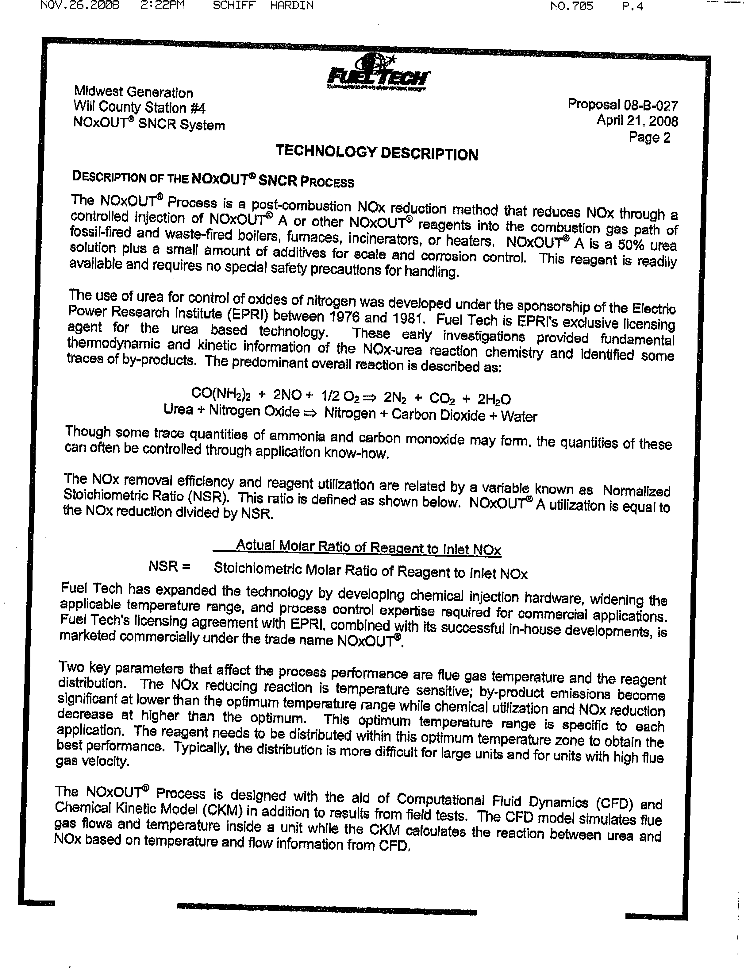
DESCRIPTION
OF
THE
NOxOUT
SNCR
PRocEss
The
NOx0UT
Process
is
a
post-combustion
NOx
reduction
method
that
reduces
NOx
through
a
controlled
injection
of
NOxOUTe
A
or
other
NOxOUT®
reagents
into
the
combustion
gas
path
of
fossil-fired
and
waste-fired
boilers,
furnaces,
incinerators,
or
heaters.
NOxOUTe
A
is
a
50%
urea
solution
plus
a
small
amount
of
additives
for
scale
and
corrosion
control.
This
reagent
is
readily
available
and
requires
no
special
safety
precautions
for
handling.
The
use
of
urea
for
control
of
oxides
of
nitrogen
was
developed
under
the
sponsorship
of
the
Electric
Power
Research
Institute
(EPRI)
between
1976
and
1981.
Fuel
Tech
is
EPRrs
exclusive
licensing
agent
for
the
urea
based
technology.
These
early
investigations
provided
fundamental
thermodynamic
and
kinetic
information
of
the
NOx-urea
reaction
chemistry
and
identified
some
traces
of
by-products.
The
predominant
overall
reaction
is
described
as:
CO(NH
2
)
2
+
2N0
+
1/202
=
2N
+
CO
2
+
2H
20
Urea
+
Nitrogen
Oxide
=
Nitrogen
+
Carbon
Dioxide
+
Water
Though
some
trace
quantities
of
ammonia
and
carbon
monoxide
may
form,
the
quantities
of
these
can
often
be
controlled
through
application
know-how.
The
NOx
removal
efficiency
and
reagent
utilization
are
related
by
a
variable
known
as
Normalized
Stoichiometric
Ratio
(NSR).
This
ratio
is
defined
as
shown
below.
NOxOUT®
A
utilization
is
equal
to
the
NOx
reduction
divided
by
NSR.
Actual
Molar
Ratio
of
Raent
to
Inlet..NOx
NSR
=
Stoichiometric
Molar
Ratio
of
Reagent
to
Inlet
NOx
Fuel
Tech
has
expanded
the
technology
by
developing
chemical
injection
hardware,
widening
the
applicable
temperature
range,
and
process
control
expertise
required
for
commercIal
applications.
Fuel
Tech’s
licensing
agreement
with
EPRI,
combined
with
its
successful
in-house
developments,
is
marketed
commercially
under
the
trade
name
NOxOUT®.
Two
key
parameters
that
affect
the
process
performance
are
flue
gas
temperature
and
the
reagent
distribution.
The
NOx
reducing
reaction
is
temperature
sensitive;
by-product
emissions
become
significant
at
lower
than
the
optimum
temperature
range
while
chemical
utilization
and
NOx
reduction
decrease
at
higher
than
the
optimum.
This
optimum
temperature
range
is
specific
to
each
application.
The
reagent
needs
to
be
distributed
within
this
optimum
temperature
zone
to
obtain
the
best
performance.
Typically,
the
distribution
is
more
difficult
for
large
units
and
for
units
with
high
flue
gas
velocity.
The
NOxOUT®
Process
is
designed
with
the
aid
of
Computational
Fluid
Dynamics
(CFD)
and
Chemical
Kinetic
Model
(CKM)
in
addition
to
results
from
field
tests.
The
CFD
model
simulates
flue
gas
flows
and
temperature
inside
a
unit
while
the
CKM
calculates
the
reaction
between
urea
and
NOx
based
on
temperature
and
flow
information
from
CFD,
Electronic Filing - Received, Clerk's Office, November 25, 2008
NOV.26.2008
2:22PM
SCHIFF
HARDIN
NO.705
P.5
Midwest
Generation
Proposal
08-8-027
WiU
County
Station
#4
April
21,
2008
NOxOUT®
SNCR
System
Page
3
TECHNOLOGY
DESCRIPTION
(-Continued-)
A
combination
of
these
two
models
determines
the
optimum
temperature
region
and
the
optimum
injection
strategy
to
distribute
the
reagent.
With
an
ability
to
estimate
NOx
reduction,
a
model
study
can
be
performed
to
determine
if
an
application
is
a
right
fit
for
the
process.
Utilizing
pressurized
air,
these
injectors
atomize
and
direct
the
NOxQUT’
reagents
Into
the
combustion
gas
path.
The
droplet
size
distribution
and
spray
coverage
developed
by
the
injectors
promote
efficient
contact
between
the
NQxQUT
5
reagents
and
the
NOx
in
the
flue
gas.
The
NOxOUT®
Process
provides
effective
boiler
load
following
capabilities.
Through
the
computer
modeling,
an
injection
strategy
is
developed
that
makes
use
of
muftilevel
injection,
control
of
reagent
concentration,
droplet
size
and
spray
patterns.
Several
years
of
field
testing
indicate
that
the
NOxOUT®
Process
is
applicable
on
various
types
of
units
firing
many
different
fuels.
The
process
was
successfully
proven
Oh
units
fired
with
coal,
oil,
gas,
wood
or
municipal
solid
or
hazardous
waste.
These
units
varied
in
size
and
type:
package
boilers,
process
heaters,
incinerators,
circulating
or
bubbling
fluidized
beds,
waste
heat
boilers,
utility
boilers.
By
virtue
of
being
a
post-combustion
process,
Unit
size
and
type
and
fuel
type
have
some,
but
not
a
major
effect
on
the
process,
There
are
substantial
benefits
gained
from
the
application
of
the
NOxOUT®
Process
compared
to
first
generation
NOx
control
technologies,
such
as
ammonia
injection.
These
benefits
are
briefly
summarized
below:
•
Use
of
non-toxic,
non-hazardous
chemicals.
•
Potentially
lower
capital
cost
due
to
the
lack
of
large
system
compressors
and
elimination
of
anhydrous
ammonia
storage,
handling,
and
safety
equipments
•
Lower
operating
costs
resulting
primarily
from
minimization
of
gas
(steam
or
compressed
air)
requirements.
•
Inherently
more
effective
control
of
spray
patterns
and
chemical
distribution
for
better
mixing
with
the
use
of
liquid
rather
than
gas-based
reagents,
thereby
resulting
in
better
chemical
utilization.
Electronic Filing - Received, Clerk's Office, November 25, 2008
NOV.26.2006
222PM
SCHIFF
HARDIN
NO.705
P.S
I-
-
-.
Midwest
Generation
Will
County
Station
Proposal
08-8-027
NOxOUT
SNCR
System
April
21,
2008
Page
4
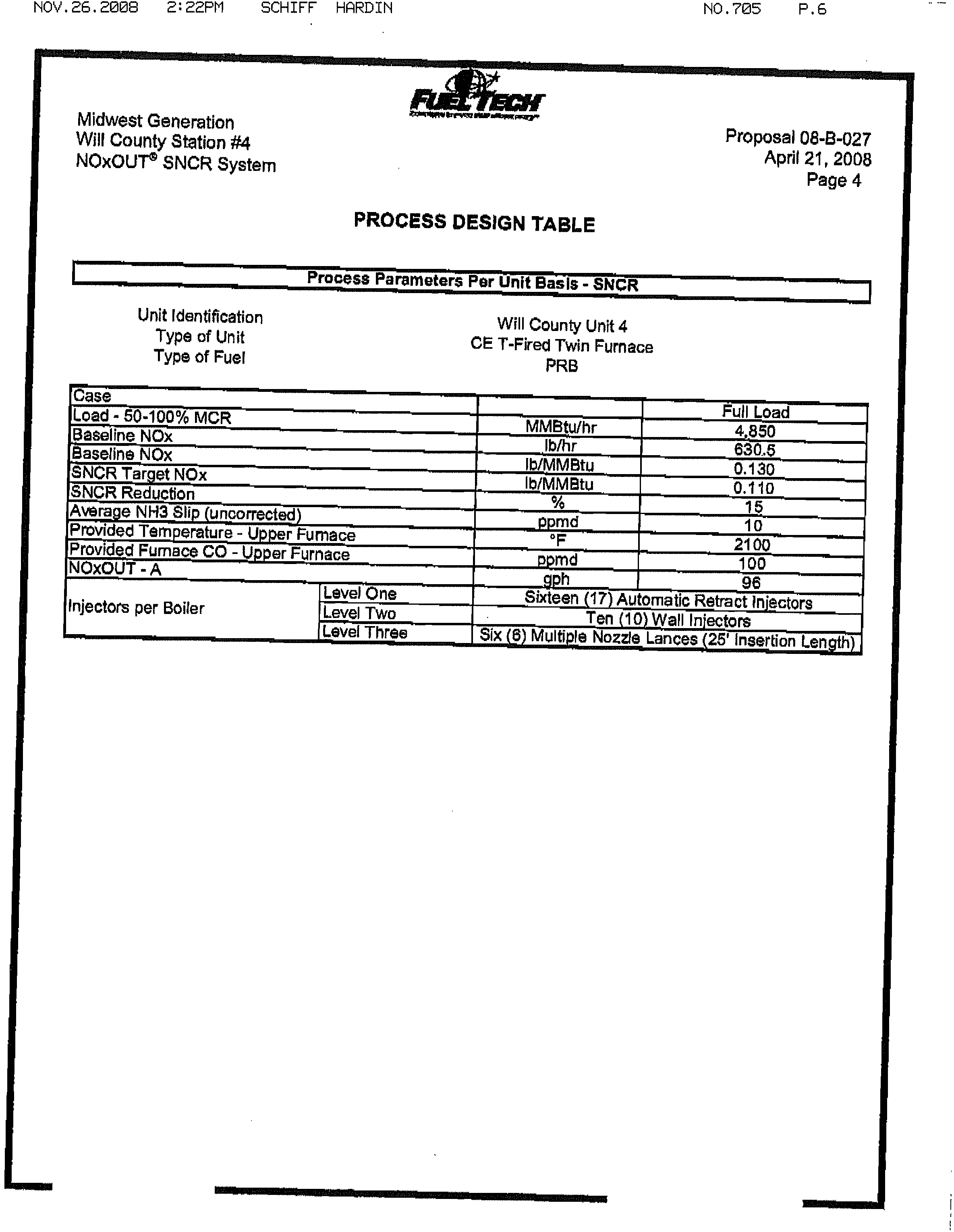
PROCESS
DESIGN
TABLE
Process
Parameters
Per
Uiiii
Basis
-
SNCR
Unit
identification
Will
County
Unit
4
Type
of
Unit
CE
T-Fireci
Twin
Furnace
Type
of
Fuel
PRB
Case
—
Full
Load
Load
-
50-100%
MCR
MMBtuThr
4,850
8ine
NOx
lb/hr
630,5
Baseline
NOx
-
lb/MMBtu
0.130
SNCR
Target
NOx
Ib/MMBtu
—
0.110
SNCR
Reduction
%
Age
NH3
Slip
(uncorrected)
ppmd
—
-.
10
Provided
Temperature
-
Upper
Furnace
—
°F
2100
ProvidedFumaceCO-UpperFurnace
-
100
NOxOUT
-
A
9
ph
.
96
iLevel
One
-
Sbcteen
(17Aiitoniatic
Retract
injectors
injectors
per
Boiler
Iiel
Two
Ten
(1Q)!aH
Injectors
—-
IhevFiThree
Six
ç
Multiple
Nozzle
Lances
(25’
Insertion
Length)
Electronic Filing - Received, Clerk's Office, November 25, 2008
NOV.26.2006
2:23PM
SCHIFF
HFIRDIN
NO.705
P.7
Midwest
Generation
Will
County
Station
#4
NOxOUT®
SNCR
System
Ac
Proposal
08-B-027
April
21,
2008
Page
5
FUEL
TECH
EQUiPMENT
SCOPE
OF
SUPPLY
[
FUEL.
TECH
EQUIPMENT
SCOPE
OF
SUPPLY
-
SNCR
Equ1ment
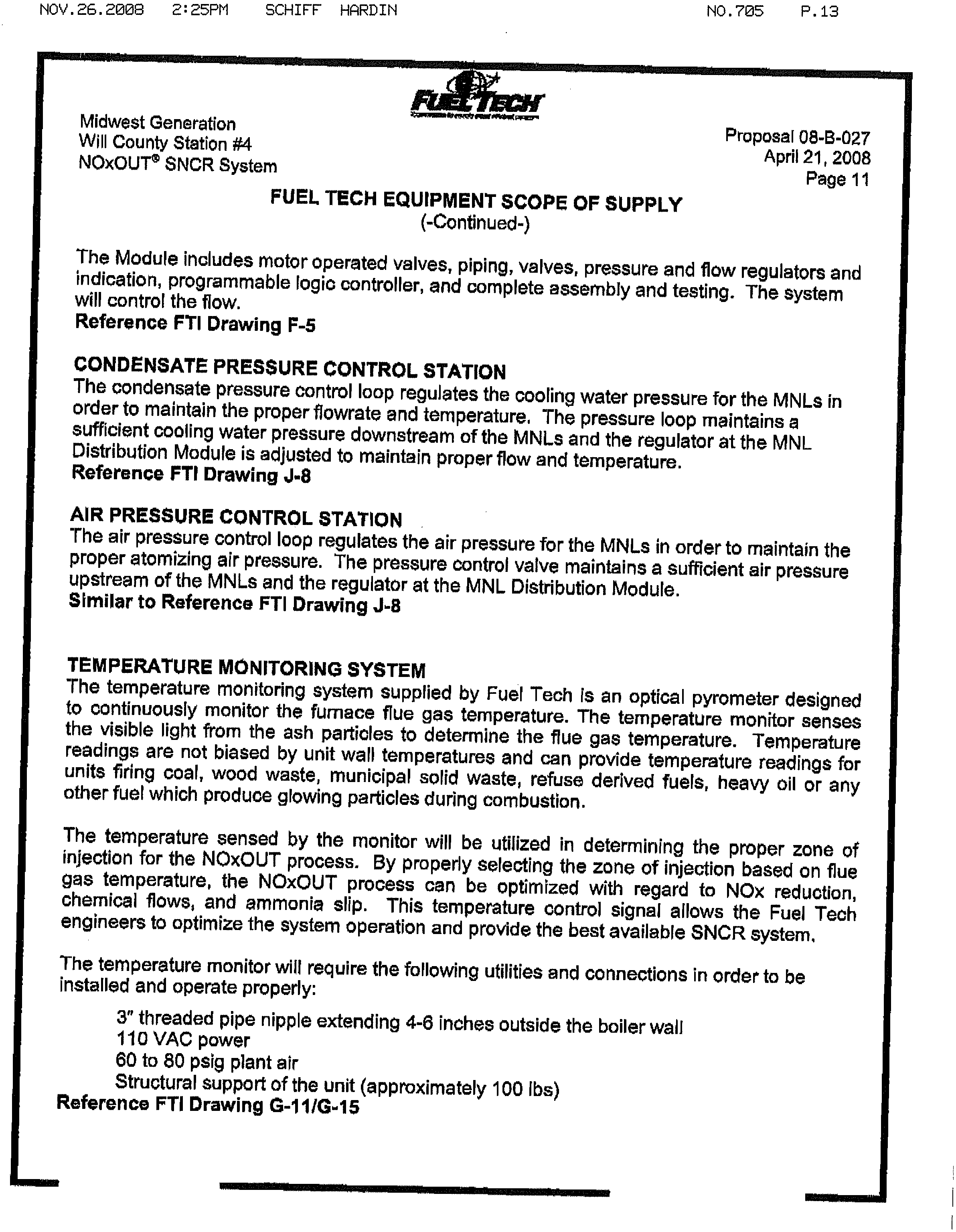
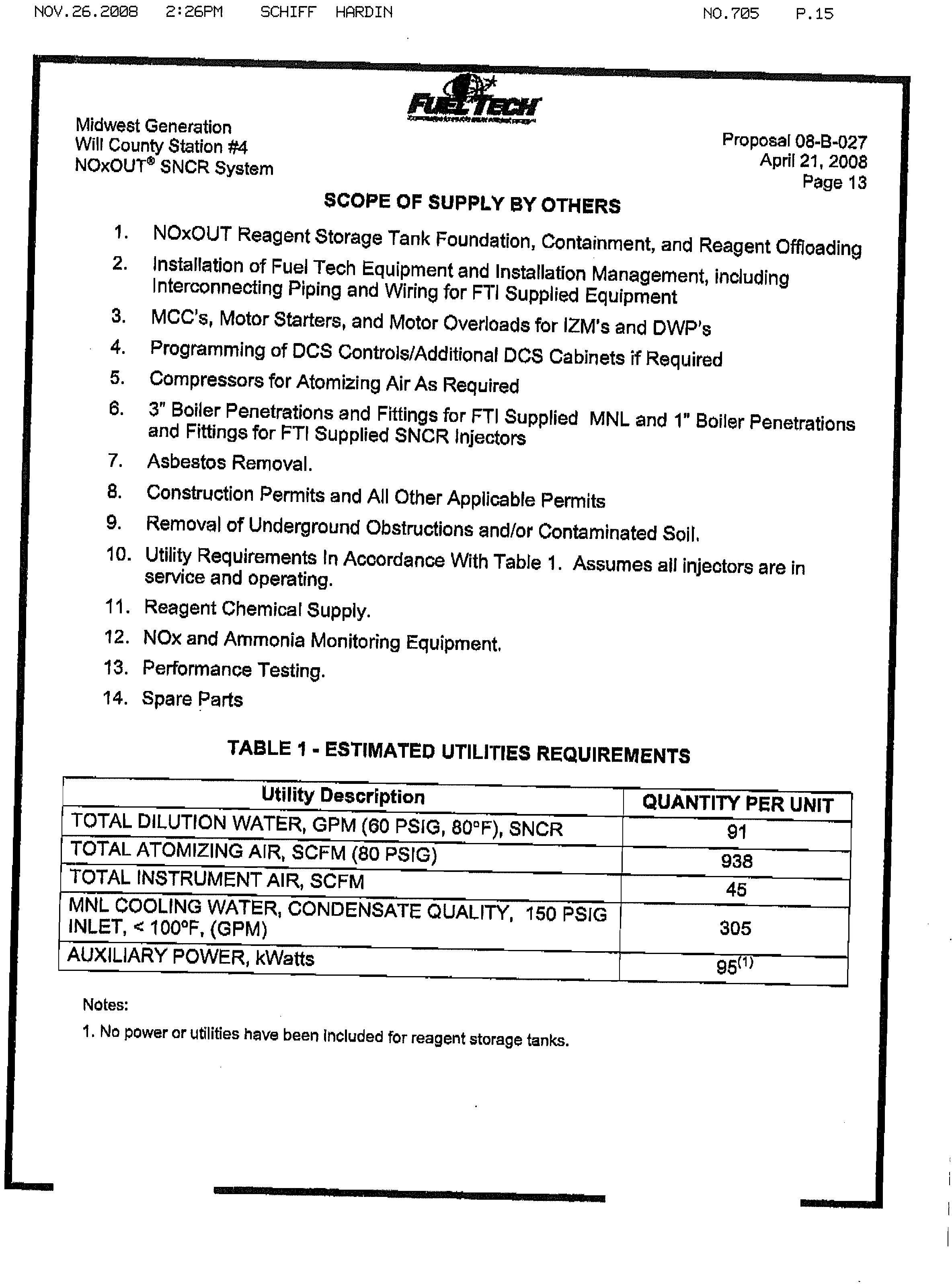
Description
—
Quantity
Reagent
Storage
Tank,
FRP,
Pre-Fabricated,
I-feat
Traced
and
Insulated
—
One
(1)
15,000
Gallon
High
Flow
Circulation
Module
wfBuildirig
w/PLC
end
Chemical
One
(1)
HFD
w/Building
Common
to
All
Circulation
Pressure
Control
-
Units
Equipment
Located
in
BuildinearBoilers)
Dilution
Water
Module
w/Remote
I/O
One
(1)-
DWP
Modules
Injection
Zone
Meteriip
Modules
w/PLC
Two
(2)
-
IZM
-2
Zone
.
.
.
Four(4)-DM-4
Distribution
Modules
(Indoor)
Two
(2)
-
DM-5
Equipment
Located
at
Boiler
Wall
Injectors
TweritSix
(26)
-
SLP3-l-FTL
Automatic
Retracts
Sixteen
(16)-
SLP3-AR
AtitomatkRetract
Control
Panels
Foui
(4)
Multiple
Nozzle
Lance
Distribution
Modules
Two
(2)
-
MNL-L)M3
Multiple
NoIe
Lances
-
Six
(6)
-
MNL’s,
25’
Inserted
LCL
MNL
Cooling
Water
arid
Air
Control
One
(1)
Temperature
Monitors
—
One
(1)
—
Man-days
Start-up/Opimlzation/Training
One
Hundred
(100)
15,000
PRP
NOxOUT®A
STORAGE
TANK
Made
of
Fiberglass
Reinforced
Plastic
(FRP)
with
Premium
Grade
Vinylester
Resin.
Fabricated
per
ASTM
D3299
where
applicable,
1.15
Specific
Gravity
heating
package
to
maintain
80
‘F,
site
specific
variables
include
seismic
zone
and
windload.
Also
includes
level
transmitter,
man-way,
vent,
internal
downpipe,
external
fill
pipe,
ladder,
hold
down
and
lifting
lugs,
FRP
flanges
for
inlet,
outlet,
and
fill
and
circulation
line
valves
for
suction
isolation,
drain,
and
return
control.
Also
included
is
heat
trace
and
insulation
with
thermostat
control.
One
Control
Panel
will
be
provided
per
tank
for
temperature
control
of
the
50%
urea
solution,
Reference
FTI
Drawing
C-I
Electronic Filing - Received, Clerk's Office, November 25, 2008
NOV.26.2009
2:23PM
SCHIFF
HRRDIN
NO.705
P.8
Midwest
Generation
Proposal
08-B-027
Will
County
Station
#4
April
21,
2008
NOxOL)T
SNCR
System
Page
6
FUEL
TECHEQUIPMENT
SCOPE
OF
SUPPLY
(-Continued-)
HIGH
FLOW
DELIVERY
(HFD)
AND
CIRCULATION
MODULE
W!BUILDING
The
HFD
Circulation
Module
is
a
self-contained
high
flow
high
head
delivery
system
designed
to
supply
filtered
aqueous
urea
reagent
to
the
Metering
Module
located
near
the
reagent
storage
tank.
An
individual
pump
will
be
utilized
to
provide
flow
to
each
boiler,
with
a
third
pump
as
a
common
spare.
This
module
serves
multiple
functions
in
the
application
of
the
Process
on
large
industrial
and
utility
scale
boilers.
The
functions
include:
•
Provides
chemical
boost
for
delivery
of
the
reagent
to
the
injection
zones
via
the
Injection
Zone
Metering
Module.
•
Filters
50%
Urea
Reagent
to
ensure
trouble
free
operation
of
the
injectors.
•
Provides
supplemental
heating
to
makeup
for
line
heating
and
losses
and
to
maintain
reagent
above
its
crystallization
temperature.
•
Maintains
a
continuous
circulation
of
the
stored
reagent.
•
Serves
as
the
local/remote
control
and
monitoring
station
for
the
reagent
storage
and
circulation
system.
•
Provides
built-in
redundancy
to
ensure
continuous
and
uninterrupted
operation.
This
module
contains
two
(2)
full-flow
multistage
SS
centrifugal
pumps,
in-line
duplex
strainer,
in-line
electric
heater
and
all
the
pressure,
temperature,
flow
and
level
instrumentation
for
local/remote
control
and
monitoring
of
the
HFD
Circulation
and
urea
storage
systems.
The
enclosures
are
constructed
of
fiberglass
reinforced
sopthalic
plastic
resin
and
molded-in
color
gel
coat
with
ultraviolet
inhibitors.
Each
building
is
specifically
designed
for
the
individual
application
with
reinforced
walls
and
flooring.
Lifting
lugs
and
structural
design
and
analysis
is
performed
where
needed.
Each
enclosure
will
include:
Specified
Fuel
Tech,
Inc.
Equipment,
Two
(2)
large
service
doors,
heater,
electrical
outlets,
lighting,
electrical
breaker
panel
with
circuits
and
transformer
specifically
sized
for
appIication
and
steel
flooring
system,
All
utility
connections
(except
for
electrical)
will
be
made
to
exterior
of
the
enclosures.
Reference
FTI
Drawing
J-1O
Electronic Filing - Received, Clerk's Office, November 25, 2008
NOV.26.2008
:23pM
SCHIFF
HARDIN
NO.705
P.9
Midwest
Generation
Proposal
08-B-027
Will
County
Station
#4
April
21,
2008
NOxOUT®
SNCR
System
Page
7
FUEL
TECH
EQUIPMENT
SCOPE
OF
SUPPLY
(-Continued-)
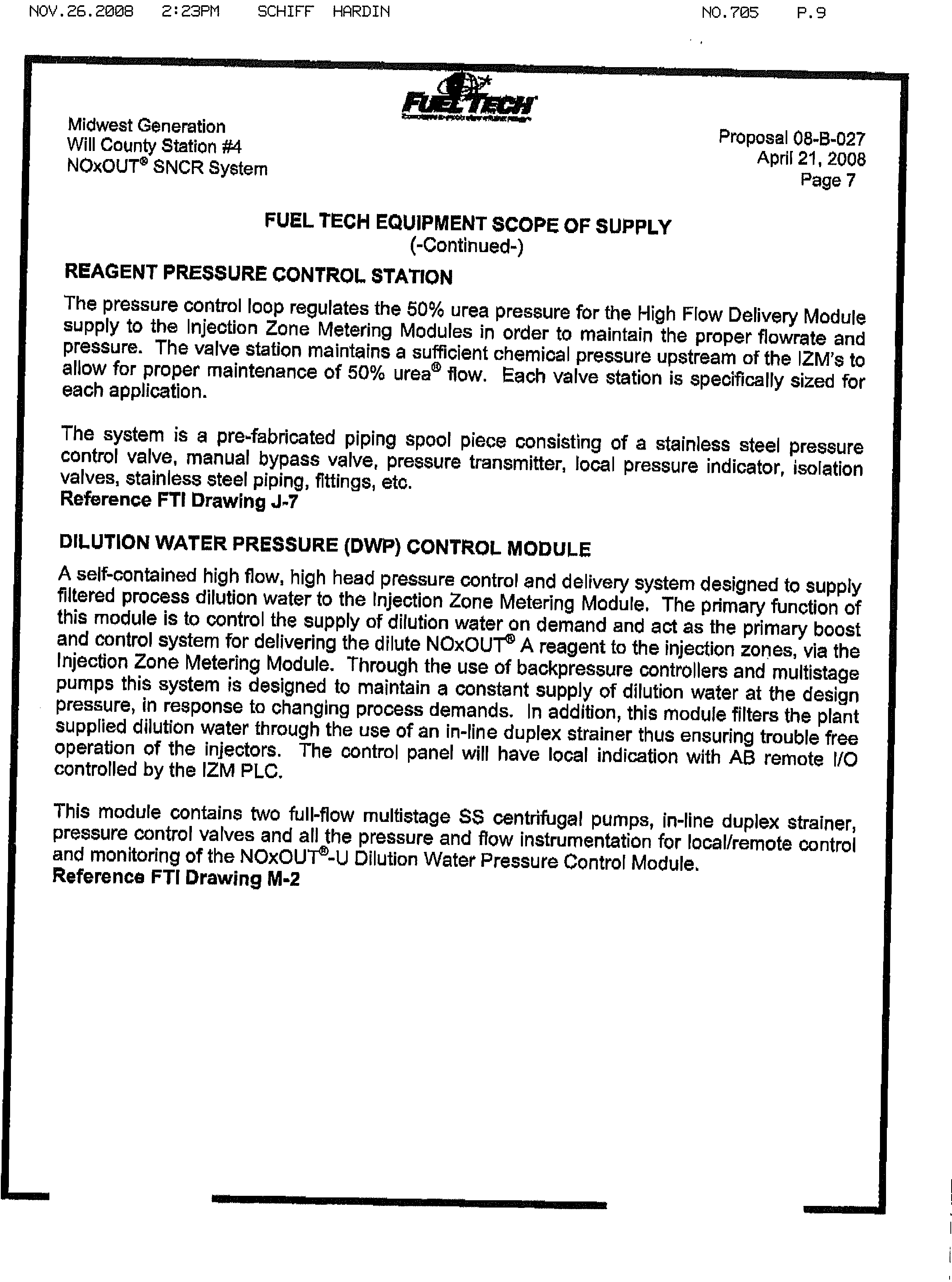
REAGENT
PRESSURE
CONTROL
STATION
The
pressure
control
loop
regulates
the
50%
urea
pressure
for
the
High
Flow
Delivery
Module
supply
to
the
Injection
Zone
Metering
Modules
in
order
to
maintain
the
proper
flowrate
and
pressure.
The
valve
station
maintains
a
sufficient
chemical
pressure
upstream
of
the
IZM’s
to
allow
for
proper
maintenance
of
50%
ureaa
flow.
Each
valve
station
is
specifically
sized
for
each
application.
The
system
is
a
pre-fabricated
piping
spool
piece
consisting
of
a
stainless
steel
pressure
control
valve,
manual
bypass
valve,
pressure
transmitter,
local
pressure
indicator,
isolation
valves,
stainless
steel
piping,
fittings,
etc.
Reference
FTI
Drawing
J-7
DILUTION
WATER
PRESSURE
(DWP)
CONTROL
MODULE
A
self-contained
high
flow,
high
head
pressure
control
and
delivery
system
designed
to
supply
filtered
process
dilution
water
to
the
Injection
Zone
Metering
Module,
The
primary
function
of
this
module
is
to
control
the
supply
of
dilution
water
on
demand
and
act
as
the
primary
boost
and
control
system
fordelivering
the
dilute
NOxOUT®
A
reagent
to
the
injection
zones,
via
the
Injection
Zone
Metering
Module.
Through
the
use
of
backpressure
controllers
and
multistage
pumps
this
system
is
designed
to
maintain
a
constant
supply
of
dilution
water
at
the
design
pressure,
in
response
to
changing
process
demands.
In
addition,
this
module
filters
the
plant
supplied
dilution
water
through
the
use
of
an
in-line
duplex
strainer
thusensuring
trouble
free
operation
of
the
injectors.
The
control
panel
will
have
local
indication
with
AG
remote
I/O
controlled
by
the
IZM
PLC.
This
module
contains
two
full-flow
multistage
SS
centrifugal
pumps,
in-line
duplex
strainer,
pressure
control
valves
and
all
the
pressure
and
flow
instrumentation
for
local/remote
control
and
monitoring
of
the
NOxOUT®-U
Dilution
Water
Pressure
Control
Module.
Reference
FTI
Drawing
M-2
Electronic Filing - Received, Clerk's Office, November 25, 2008
NOV.26.2008
2:24PM
SCHIFF
HARDIN
NO.705
P.10
Midwest
Generation
Proposal
08-8-027
Will
County
Station
#4
ApriL
21,
2008
NOxOUT
SNCR
System
Page
8
FUEL
TECH
EQUIPMENT
SCOPE
OF
SUPPLY
(-Continued-)
INJECTOR
ZONE
METERING
(IZM)
MODULE
The
IZM
is
the
primary
module
used
to
precisely
meter
and
independently
control
the
concentration
of
NOxOUr°
A
reagent
to
each
zone
of
injection
in
a
large
Industrial
or
Utility
Boiler
application
of
the
NOxOUt
process.
This
module,
through
the
use
of
independent
chemical
flow
control
and
zone
pressure
control
valves
integrated
with
local
programmable
PID
controllers,
provides
an
increased
level
of
process
control
needed
in
these
complex
applications.
This
module
is
designed
to
interface
with
the
plant
Distributed
Control
System
(DCS).
The
IZM
Module
automatically
adjusts
reagent
flows
and
activates
or
deactivates
injection
zones
or
control
zone
mass
flows,
in
response
to
changes
in
NOx
level,
boiler
load,
fuel
or
firing
configurations.
This
unit
will
contain
an
AB
SLC
PLC
with
PanelView
1000
Operator
Interface
and
an
air
conditioning
unit
to
maintain
appropriate
internal
panel
operating
temperatures.
Each
zone
sub-module
of
the
IZM
is
designed
to
be
operated
and
controlled
independent
of
each
other.
This
feature
permits
individual
isolation
of
each
sub-module
for
maintenance
without
severely
impacting
process
performance
or
overall
NOx
reductions.
The
standard
unit
includes
a
stainless
steel,
freestanding
base
with
integrated
containment
basis,
master
interlock
trip
panel,
instrument
and
atomizing
air
pressure
switches
and
instrument
air
regulator.
Each
zone-metering
sub-module
includes
local/remote
selectors,
manual/off/auto
selection
for
flow
and
pressure
control,
local/remote
process
flow
and
pressure
control
with
display,
chemical
and
water
control
valves,
and
inline
static
mixer.
Reference
FTI
Drawing
M-3
SLP3-DM4
and
DM5
DISTRIBUTION
MODULES
These
are
placed
just
prior
to
the
injectors
(typically
at
the
same
elevation)
and
are
used
as
a
guide
and
check
for
proper
injector
performance.
Air
for
atomization
and
cooling
is
introduced
through
this
module.
One
panel
is
supplied
for
each
injector.
They
are
grouped
and
pipe
manifolded
together
for
ease
of
installation.
Also
includes
the
necessary
panels
per
module.
Complete
assembly
and
testing,
flow
and
pressure
indication
with
regulators
for
chemical
and
atomizing
air.
Each
panel
will
be
mounted
to
a
free-standing
stainless
steel
base
and
a
pipe-manifold
assembled
for
easy
flow
accessibility.
Typical
Size;
DM-4
(2’Wx
3.5’L
x
67-I)
Approximate
weight:
300
lbs
Typical
Size:
DM-5
—
(2’Wx
5.5’L
x
6’H)
Approximate
weight:
500
lbs
Reference
FTI
Drawings
F-I
&
F-6
Electronic Filing - Received, Clerk's Office, November 25, 2008
NOV.26.2008
2:24PM
SCHIFF
HARDIN
NO.705
P.11
Midwest
Generation
Proposal
Will
08-B-027
County
Station
#4
April
21
2008
NOxOUT
SNCR
System
Page
9
FUEL
TECH
EQUIPMENT
SCOPE
OF
SUPPLY
(-Continued-)
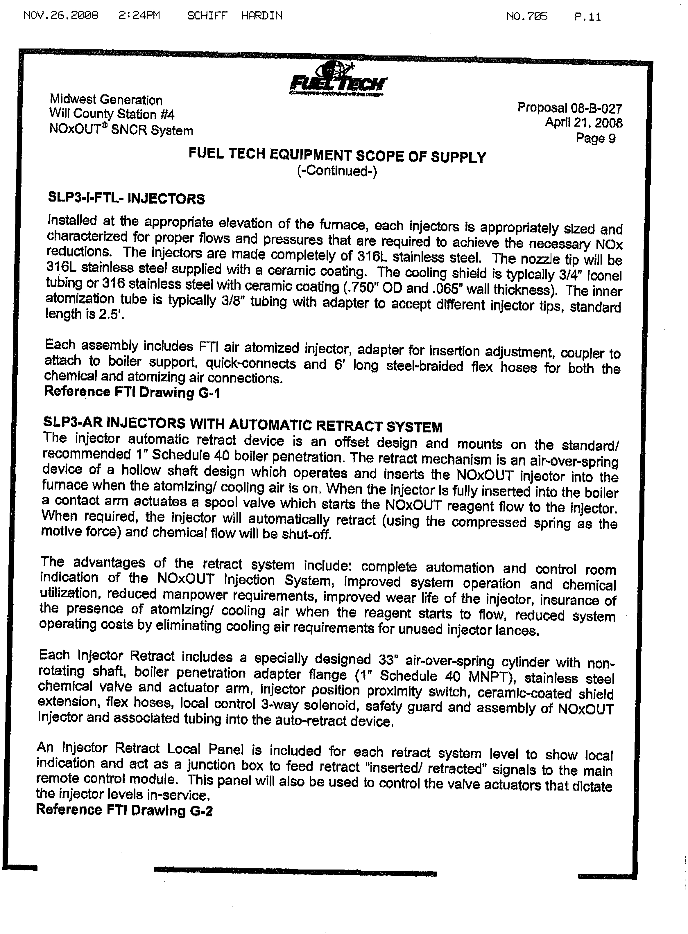
SLP3-I-FTL-
INJECTORS
Installed
at
the
appropriate
elevation
of
the
furnace,
each
injectors
is
appropriately
sized
and
characterized
for
proper
flows
and
pressures
that
are
required
to
achieve
the
necessary
NOx
reductions.
The
injectors
are
made
completely
of
316L
stainless
steel.
The
nozzle
tip
will
be
316L
stainless
steel
supplied
with
a
ceramic
coating.
The
cooling
shield
is
typically
314”
lconel
tubing
or
316
stainless
steel
with
ceramic
coating
(.750”
OD
and
.065”
wall
thickness).
The
inner
atomization
tube
is
typically
3/8”
tubing
with
adapter
to
accept
different
injector
tips,
standard
length
is
2.5’.
Each
assembly
includes
FT1
air
atomized
injector,
adapter
for
insertion
adjustment,
coupler
to
attach
to
boiler
support,
quickconnects
and
6’
long
steel-braided
flex
hoses
for
both
the
chemical
and
atomizing
air
connections.
Reference
ET1
Drawing
G-1
SLP3.AR
INJECTORS
WITH
AUTOMATIC
RETRACT
SYSTEM
The
injector
automatic
retract
device
is
an
offset
design
and
mounts
on
the
standard!
recommended
1”
Schedule
40
boiler
penetration.
The
retract
mechanism
is
an
air-over-spring
device
of
a
hollow
shaft
design
which
operates
and
inserts
the
NOxOUT
injector
into
the
furnace
when
the
atomizing!
cooling
air
is
on
When
the
injector
is
fully
inserted
into
the
boiler
a
contact
arm
actuates
a
spool
valve
which
starts
the
NOxOUT
reagent
flow
to
the
injector.
When
required,
the
injector
will
automatically
retract
(using
the
compressed
spring
as
the
motive
force)
and
chemical
flow
will
be
shut-off.
The
advantages
of
the
retract
system
include:
complete
automation
and
control
room
indication
of
the
NOxOUT
Injection
System
improved
system
operation
and
chemical
utilization,
reduced
manpower
requirements,
improved
wear
life
of
the
injector,
insurance
of
the
presence
of
atomizing!
cooling
air
when
the
reagent
starts
to
flow,
reduced
system
operating
costs
by
eliminating
cooling
air
requirements
for
unused
injector
lances,
Each
Injector
Retract
includes
a
specially
designed
33”
air-over-spring
cylinder
with
non,
rotating
shaft,
boiler
penetration
adapter
flange
(1”
Schedule
40
MNPT),
stainless
steel
chemical
valve
and
actuator
arm,
injector
position
proximity
switch,
ceramic-coated
shield
extension
1
flex
hoses,
local
control
3-way
solenoid,
safety
guard
and
assembly
of
NOxOUT
Injector
and
associated
tubing
into
the
auto-retract
device,
An
lnjector
Retract
Local
Panel
is
included
for
each
retract
system
level
to
show
local
indication
and
act
as
a
junction
box
to
feed
retract
“inserted)
retracted
1
’
signals
to
the
main
remote
control
module.
This
panel
will
also
be
used
to
control
the
valve
actuators
that
dictate
the
injector
levels
in-service.
Reference
FTI
Drawing
G-2
Electronic Filing - Received, Clerk's Office, November 25, 2008
Nov.26.2009
2:25PM
SCHIFF
HRRDIN
MO.’705
P.12
Midwest
Generation
Proposal
08-3-027
Will
County
StatIon
#4
April
21,
2008
NOxOLJT®
SNCR
System
Page
10
FUEL
TECH
EQUIPMENT
SCOPE
OF
SUPPLY
(-Continued-)
RETRACT
CONTROL
PANEL.
An
Injector
Retract
Control
Panel
is
need
for
each
retract
system
to
provide
local
indication
of
the
injector
status
and
act
as
a
junction
box
to,feed
retract
“inserted/
retracted”
signals
to
the
main
control
module.
This
panel
will
also
be
used
to
control
the
valve
actuators
that
dictate
the
injector
levels
in.
service.
MULTIPLE
NOZZLE
LANCE
(MNL),
26’
Inserted
Length
The
Multiple
Nozzle
Lance
is
designed
to
provide
chemical
coverage
in
locations
where
the
standard
wall-mounted
lance
cannot
produce
the
necessary
coverage.
Each
MNL
is
supplied
with
a
retract
mechanism
to
remove
the
lance
from
the
boiler
cavity
when
the
lance
is
not
in
use,
or
in
the
event
of
a
loss
of
cooling
water
flow,
high
cooling
water
temperature
or
loss
of
atomization
air
flow.
This
lance
is
designed
using
the
principle
of
air
atomization
and
consists
of
pairs
of
nozzles
that
are
spaced
along
the
length
of
the
lance
to
provide
a
fine
chemical
spray
into
the
back
pass
flue
gases.
Nozzles
are
spaced
at
intervals
along
the
length
of
the
lance
and
may
be
altered
in
order
to
provide
better
chemical
utilization
and
control
of
ammonia
slip.
The
lance.
will
require
a
distribution
panel
which
will
control
the
chemical
mixture
and
air
flows
to
the
lance
end
a
panel
to
monitor
and
control
the
cooling
water
flow
and
temperature
as
well
as
the
retract
mechanism.
The
standard
MNL
will
be
inserted
through
an
8
-
10”
diameter
opening.
Retract
mechanisms
are
similar
to
soot
blower
retract
mechanisms.
These
lances
and
retracts
are
custom
designed
for
each
application
to
provide
the
chemical
coverage
required
as
determined
by
the
Process
Engineering
Department.
Reference
FTI
Drawing
G-17
MULTIPLE
NOZZLE
LANCE
(MNL)
DISTRIBUTION
MODULES
The
Multiple
Nozzle
Lance
Distribution
Modules
are
placed
prior
to
the
Multi-Nozzle
Lances
and
are
used
to
control
the
injection
rate
of
atomizing/cooling
air,
mixed
chemical,
and
cooling
water.
Air
and
mixed
chemical
may
be
regulated
at
the
module
to
produce
the
proper
air/liquid
mass
ratios
that
produce
the
optimum
NOx
reduction,
Each
Module
is
designed
to
control
the
injection
rate
of
two
(2)
MNLs.
Control
of
the
MNL
Distribution
Module
is
achieved
through
the
use
of
a
local
programmable
logic
controller.
The
system
may
be
operated
in
local
operation
at
the
local
control
panel
or
may
be
operated
in
remote
mode
from
the
Master
Control
Module.
Electronic Filing - Received, Clerk's Office, November 25, 2008
NOV.26.2008
2:25PM
SCHIFF
HRRDIN
NO.705
P.13
--
III
Midwest
Generation
Proposal
08-B-027
WVI
County
Station
#4
April
21,
2008
NOxOUT®
SNCR
System
Page
11
FUEL
TECH
EQUIPMENT
SCOPE
OF
SUPPLY
(-Continued-)
The
Module
includes
motor
operated
valves,
piping,
valves,
pressure
and
flow
regulators
and
indication,
programmable
logic
controller,
and
complete
assembly
and
testing.
The
system
will
control
the
flow.
Reference
FTI
Drawing
F-5
CONDENSATE
PRESSURE
CONTROL
STATION
The
condensate
pressure
control
loop
regulates
the
cooling
water
pressure
for
the
MNLs
in
order
to
maintain
the
proper
flowrate
and
temperature,
The
pressure
loop
maintains
a
sufficient
cooling
water
pressure
downstream
of
the
MNLs
and
the
regulator
at
the
MNL
Distribution
Module
is
adjusted
to
maintain
proper
flow
and
temperature.
Reference
FTI
Drawing
J-8
AIR
PRESSURE
CONTROL
STATION
The
air
pressure
control
loop
regulates
the
air
pressure
for
the
MNLs
in
order
to
maintain
the
proper
atomizing
air
pressure.
The
pressure
control
valve
maintains
a
sufficient
air
pressure
upstream
of
the
MNLs
and
the
regulator
at
the
MNL
Distribution
Module.
Similar
to
Reference
FTI
Drawing
J-B
TEMPERATURE
MONITORING
SYSTEM
The
temperature
monitoring
system
supplied
by
Fuel
Tech
is
an
optical
pyrometer
designed
to
continuously
monitor
the
furnace
flue
gas
temperature.
The
temperature
monitor
senses
the
visible
light
from
the
ash
particles
to
determine
the
flue
gas
temperature.
Temperature
readings
are
not
biased
by
unit
wall
temperatures
and
can
provide
temperature
readings
for
units
firing
coal,
wood
waste,
municipal
solid
wastes
refuse
derived
fuels,
heavy
oil
or
any
other
fuel
which
produce
glowing
particles
during
combustion.
The
temperature
sensed
by
the
monitor
will
be
utilized
in
determining
the
proper
zone
of
injection
for
the
NOxOUT
process.
By
properly
selecting
the
zone
of
injection
based
on
flue
gas
temperature,
the
NOxCUT
process
can
be
optimized
with
regard
to
NOx
reduction,
chemical
flows
and
ammonia
slip.
This
temperature
control
signal
allows
the
Fuel
Tech
engineers
to
optimize
the
system
operation
and
provide
the
best
available
SNCR
system.
The
temperature
monitor
will
require
the
following
utilities
and
connections
in
order
to
be
installed
and
operate
properly:
3”
threaded
pipe
nipple
extending
4-8
inches
outside
the
boiler
wall
110
VAC
power
60
to
80
psig
plant
air
Structural
support
of
the
unit
(approximately
100
Ibs)
Reference
FTI
Drawing
G-IIIG-15
Electronic Filing - Received, Clerk's Office, November 25, 2008
NOV.26.2ØØS
2:25PM
SCHIFF
HRDIN
NO7Ø5
P14
Midwest
Generation
Proposal
Will
08-B-027
County
Station
#4
April
21,
2008
NOxOUT®
SNCR
System
Page
12
FUEL
TECH
EQUIPMENT
SCOPE
OF
SUPPLY
(-Continued-)
ENGINEERING:
Fuel
Tech
will
provide
Project
and
Process
Engineering
and
the
following
drawingsand
information;
-
P&ID’s
-
Mechanical
Drawings
Include
•
General
Arrangements
and
Module
layout
•
Bill
of
Materials
•
Dead
Weights
and
Sizes
-
Electrical
Drawings
including:
Schematics
•
External
Connection
Diagrams
(Field
Terminations)
•
Electrical
Bill
of
Materials
•
Logic
Diagrams
-
Interface
Drawings
-
Injector
location
Drawings
and
Modeling
Report(s)
-
Equipment
arid
Instrument
Data
Sheets
-
O&M
Manuals
The
Dilution
Water,
Injection
Zone
Metering,
and
Distribution
Modules
Will
be
skid
mounted
with
all
equipment,
piping,
instruments,
electrical
arid
controls
shop
assembled,
Installation
by
others
will
require
interconnecting
mechanical
and
electrical.
The
Dilution
Water
1
Injection
Zone
Metering,
and
Distribution
Modules
must
be
located
indoors
for
freeze
protection
Size,
weight
and
electrical
requirements
are
specified
on
the
drawings.
All
control
devices
require
field
installation.
ENGINEERING
SERV1CES:
-
Process
and
Project
Engineering
-
Temperature
and
Species
Mapping
-
One
Hundred
(100)
Mandays
for
Start
Up,
Optimization,
and
Training
-
Operation
and
Maintenance
Manuals
(5)
-
Three
(3)
Formal
Drawing
Submittals,
including:
1.
For
Approval
Submittal
2,
Release
for
Construction
Submittal
3.
As-Buift
Submittals
Any
additional
submittals
required
by
Owner
or
Owner’s
Engineer
shall
be
provided
at
an
additional
charge.
Electronic Filing - Received, Clerk's Office, November 25, 2008
NOV.26.2008
2:26PM
SCHIFF
HARDIN
NO.705
P.15
Midwest
Generation
Proposal
08-B-027
WHI
County
Station
#4
April
21,
2008
NOxOUT®
SNCR
System
Page
13
SCOPE
OF
SUPPLY
BY
OThERS
1.
NOxOUT
Reagent
Storage
Tank
Foundation,
Containment,
and
Reagent
Offloading
2.
Installation
of
Fuel
Tech
Equipment
and
Installation
Management,
including
Interconnecting
Piping
and
Wiring
for
FTI
Supplied
Equipment
3.
MCC’s,
Motor
Starters,
and
Motor
Overloads
for
IZM’s
and
DWP’s
4.
Programming
of
DCS
Controls/Additional
DOS
Cabinets
if
Required
5.
Compressors
for
Atomizing
Air
As
Required
6.
3”
Boiler
Penetrations
and
Fittings
for
FTI
Supplied
MNL
and
1”
Boiler
Penetrations
and
Fittings
for
FTI
Supplied
SNCR
Injectors
7.
Asbestos
Removal.
8.
Construction
Permits
and
All
Other
Applicable
Permits
9.
Removal
of
Underground
Obstructions
and/or
Contaminated
Soil.
10.
Utility
Requirements
In
Accordance
With
Table
1.
Assumes
all
injectors
are
in
service
and
operating.
II.
Reagent
Chemical
Supply.
12.
NOx
and
Ammonia
Monitoring
Equipment.
13.
Performance
Testing.
14.
Spare
Parts
TABLE
I
-
ESTIMATED
UTILITIES
REQUIREMENTS
Utility
Description
-
QUANTITY
PER
UNIT
TOTAL
DILUT1ON
WATER,
GPM
(60
PSIG,
80°F),
SNCR
91
TOTAL
ATOMIZING
AIR,
SCFM
(80
PSIG)
938
TOTAL
INSTRUMENT
AIR,
SCFM
45
MNL
COOLING
WATER,
CONDENSATE
QUALITY,
150
PSIG
305
INLET,
100°F,
(GPM)
AUXILIARY
POWER,
kWatts
95(1)
Notes:
1.
No
power
or
utilities
have
been
Included
for
reagent
storage
tanks.
Electronic Filing - Received, Clerk's Office, November 25, 2008
NOV.26.2006
2:26PM
SCHIFF
HRDIN
NO.705
P.16
Midwest
Generation
Proposal
Will
08-6-027
County
Station
#4
April
21,
2008
NOxOUT
SNOR
System
Page
14
PRICING
AND
PAYMENT
TERMS
PRICE
-
NOxOUTSNCR
SYSTEM:
For
the
Project
Engineering
Equipment,
Testing,
Startup,
Optimization,
and
Training
as
defined
for
Midwest
Generation
Will
County
Station
Unit
#4
Fuel
Tech
quotes
the
firm
price
of:
TERMS
OF
PAYMENT:
10%
Upon
Receipt
of
signed
Letter
of
Intent,
Purchase
Order
or
Contract
Whichever
Occurs
First,
Between
Fuel
Tech,
mo.
and
I3uyer.
40%
Upon
submittal
of
Drawings
to
the
Buyer
for
Approval.
40%
Upon
Date
of
shipment
of
Equipment,
or
Thirty
Days
After
NoUfication
to
Buyer
that
Equipment
is
Ready
to
Ship,
whichever
Occurs
First.
10%
After
Successful
Completion
of
Startup,
or
six
(6)
Months
after
Delivery
of
Equipment
to
Customer
Site,
whichever
occurs
first.
Electronic Filing - Received, Clerk's Office, November 25, 2008
NOV.26.2009
2:26PM
SCHIFF
HARDIN
NO.705
P.17
Midwest
Generation
Proposal
08-B-027
Will
County
Station
#4
April
21,
2008
NOxOUT®
SNCR
System
Page
15
EXH!!T
C3
IEL
TECHI
C.
STANDARD
TERMS
and.
CONDITION
These
terms
and
conditions
shall
be
part
of
the
attached
proposal
and
shall
become
part
of
the
contract
entered
into
between
FUEL
TECH,
INC.
(Fuel
Tech),
and
the
Buyer.
Deviations
from
these
terms
and
conditions
must
be
agreed
to
in
a
writing
signed
by
Fuel
Tech
and
the
Buyer.
Fuel
Tech
hereby
gives
notice
of
its
objection
to
any
different
or
additional
terms
or
conditions
unless
such
different
or
additional
terms
or
conditions
are
agreed
to
in
a
writing
signed
by
Fuel
Tech
and
Buyer.
1.
TERMS
OF
PAYMENT:
All
invoices
are
payable
net
thirty
(30)
days
from
date
of
invoice,
Buyer
shall
pay
interest
at
the
rate
of
ten
percent
(10%)
per
annum
on
all
overdue
amounts.
Buyer
shall
pay
all
sales
tax,
use
tax,
excise
tax,
or
other
similar
taxes.
2.
DELAYS:
If
shipments
are
delayed
by
Buyer,
payment
shall
be
due
on
and
warranty
coverage
shall
begin
to
run
from
thirty
days
after
the
original
shipment
date
specified
in
the
contract
or
thirty
(30)
days
after
notification
to
Buyer
that
equipment
is
ready
to
ship,
whichever
is
earlier.
Risk
of
loss
shall
pass
to
Buyer
at
the
time
that
equipment
is
identified,
and
any
costs
caused
by
such
delay
shall
be
borne
by
Buyer.
If
shipments
are
delayed
by
Buyer,
Fuel
Tech
will
ship
the
equipment
no
later
than
sixty
(60)
days
after
initial
notification
to
the
Buyer
that
the
equipment
is
ready
for
shipment.
Buyer
agrees
either
(1)
to
provide
Fuel
Tech
an
appropriate
“ship
to”
address
and
to
accept
delivery
or
(2)
pay
reasonable
storage
charges
for
the
equipment
beginning
sixty
(60)
days
after
initial
notification
to
Buyer
that
equipment
is
ready
to
ship.
3.
PERFORMANCE
GUARANTEE:
Buyer
warrants
that
the
operating
conditions
of
the
Unit
are
those
specified
in
the
Process
Design
Table.
Buyer
is
solely
responsible
for
the
accuracy
of
that
operating
condition
information,
and
all
performance
guarantees
and
equipment
warranties
granted
by
Fuel
Tech
shall
be
void
if
that
operating
condition
information
is
inaccurate
or
is
not
met.
All
performance
guarantees
and
equipment
warranties
are
conditioned
on
Buyer
timely
providing
all
of
the
equipment,
Electronic Filing - Received, Clerk's Office, November 25, 2008
NOV.26.2008
2:26PM
SCHIFF
HARDIN
NO.705
P.18
Midwest
Generation
Proposal
O8-B027
Will
County
Station
#4
April
21
2008
NOxOUT® SNOR
System
Page 16
EXHIBIT
C3
FUEL
TECHJNC.
STANDARD
TERMS
AND
CONDITIONS
(-CONTINUED-)
materials,
chemicals,
utilities,
and
services
that
it
has
agreed
to
provide,
on
operating
the Unit
within
the
operating
conditions
specified
in
the
Process
Design
Table,
and
on
using
reagent
of
license
grade
quality
in
the
operation
of
the
Unit.
4.
EQUIPMENT
WARRANTY:
Fuel Tech
warrants
that
the
equipment
it
provides
shall
be
free
from
defects
in
design,
workmanship,
and
material
at
the time
the
equipment
is
delivered
and
for
a
period
of
twelve
(12) months
after initial
operation,
or
eighteen
(18) months
from
shipment
of
equipment,
whichever
occurs
first.
Fuel
Tech
does
not warrant
wear
parts such
as
injection tips,
cooling
shields,
pump
diaphragms,
check
valves,
solenoids,
pump
impellers,
pump wear
rings,
pump
seals,
valve
packing,
and
valve
seats.
All
warranties
made
by
the
manufacturer
of
the
equipment
(if
that
manufacturer
is
any
entity other
than
Fuel
Tech)
shall be
assigned
by
Fuel
Tech
to the
Buyer,
if
such
assignment
is
permissible
by
law and
contract,
Warranty
coverage
starts at
shipment
of
equipment
or
thirty (30) days
after
notification
to
Buyer
that equipment
is
ready
to
ship.
5.
DISCLAIMER
OF
WARRANTIES:
Fuel
Tech
warrants
its
equipment
and
the
performance
of
its
equipment
solely
in
accordance
with
the equipment
warranty
and
performance
guarantee
contained
in
this
proposal
and
makes
no
other
representations
or
warranties
of
any
other
kind, express
or
implied,
by
fact
or
by
law. All
warranties
other than
those
specifically
set
forth
in
this
proposal are
expressly
disclaimed.
FUEL
TECH
SPECIFICALLY
DISCLAIMS
ALL
OTHER
WARRANTIES,
EXPRESS
OR
IMPLIED,
AND
DISLCAIMS
THE IMPLIED
WARRANTY
OF
MERCHANTABILITY
THE
IMPLIED
WARRANTY
OF
FITNESS
FOR
A
PARTICULAR
PURPOSE,
AND
ANY
OTHER
IMPLIED
WARRANTIES
OF
DESIGN,
CAPACITY,
OR
PERFORMANCE
RELATING
TO
THE
EQUIPMENT.
6.
LIMITATION
OF LIABILITY:
Buyer’s
sole
remedy
under
the
equipment
warranty
and
the
performance
guarantee
shall
be
to
allow
Fuel Tech,
at
Fuel Tech’s
option,
either
to
repair,
replace,
or
supplement
the
equipment
to
meet
the
performance
guarantee,
or,
in
the
event
that
those
options
are
not
feasible,
to
remove
the
Equipment
and
refund
the
contract
price
to
Buyer.
Electronic Filing - Received, Clerk's Office, November 25, 2008
NOV.26.2008
2:27PM
SCHIFF
HARDIN
NO.705
P.19
Midwest
Generation
Proposal
08-B
-027
Will
County
Station
#4
April
21,
2008
NOxQUT
SNCR
System
Page
17
EXHIBITC3
FUEL
TECH.
lN.
STANQARD
TERMS
AND
CONDITIONS
(-CONTINUED-)
NOTWITHSTANDING
ANYTHING
TO
THE
CONTRARY,
FUEL
TECH’S
TOTAL
LIMIT
OF
LIABILITY
ON
ANY
CLAIM,
WHETHER
FOR
BREACH
OF
CONTRACT,
BREACH
OF
WARRANTY,
TORT,
NEGLIGENCE,
STRICT
LIABILITY,
OR
ANY
OTHER
LEGAL
THEORY,
FOR
ANY
LOSS
OR
DAMAGE
ARISING
OUT
OF,
OR
CONNECTED
TO,
OR
RESULTING
FROM
THIS
AGREEMENT,
INCLUDING
WITHOUT
LIMITATION
AMOUNTS
INCURRED
BY
FUEL
TECH
OR
BUYER
IN
ATTEMPTING
TO
REPAIR,
REPLACE,
OR
SUPPLEMENT
THE
EQUIPMENT
OR
MEET
THE
PERFORMANCE
GUARANTEE,
SHALL
BE
LIMITED
TO
THE
CONTRACT
PRICE
TO
BE
PAID
BY
BUYER
PURSUANT
TO
THE
CONTRACT,
7.
EXCLUSION
OF
CONSEQUENTIAL
DAMAGES:
NOTWITHSTANDING
ANYTHING
TO
THE
CONTRARY,
IN
NO
EVENT
SHALL
FUEL
TECH
BE
LIABLE
FOR
ANY
INDIRECT,
CONSEQUENTIAL,
INCIDENTAL,
SPECIAL,
OR
PUNiTIVE
DAMAGES,
INCLUDING
BUT
NOT
LIMITED
TO
LOSS
OF
CAPITAL,
LOSS
OF
REVENUES,
LOSS
OF
PROFITS,
LOSS
OF
ANTICIPATORY
PROFITS,
LOSS
OF
BUSINESS
OPPORTUNITY,
DAMAGE
TO
EQUIPMENT
OR
FACILITIES,
COST
OF
SUBSTITUTE
NOx
REDUCTION
SYSTEMS,
DOWNTIME
COSTS,
GOVERNMENT
FINES,
OR
CLAIMS
OF
CUSTOMERS,
EVEN
IF
ADVISED
OF
THE
POSSIBiLITY
OF
SUCH
DAMAGES.
8.
RESPONSIBILITY
FOR
THIRD
PARTiES
Buyer
shall
at
all
times
be
responsible
for
the
acts
and
omissions
of
its
subcontractors
and
of
any
other
third
parties
hired
or
retained
or
contracted
by
Buyer
to
perform
work
or
provide
equipment
related
to
the
system
provided
by
Fuel
Tech,
including
but
not
limited
to
third
party
design,
systems
integration,
equipment
tie-in,
or
process
design
changes.
Fuel
Tech
shall
have
no
responsibility
for
ensuring
the
accuracy
of
any
such
work
or
the
performance
of
any
equipment
provided
by
subcontractors
or
third
parties
hired
or
retained
or
contracted
by
Buyer,
and
Buyer
assumes
all
liability
for
any
such
work
or
equipment
and
for
any
failures
in
Fuel
Tech’s
equipment
caused
by
any
such
subcontractors
or
third
parties
hired
or
retained
or
contracted
by
Buyer.
Buyer
agrees
to
indemnify,
hold
harmless,
and
defend
Fuel
Tech
from
any
claims,
losses,
damages,
injuries,
or
failures
caused
by
any
such
subcontractors
or
third
parties.
Electronic Filing - Received, Clerk's Office, November 25, 2008
NOV.26.2008
2:27PM
SCHIFF
HRRDIN
NO.705
P.20
Midwest
Generation
Propossi
08-B-027
Will
County
Station
#4
April
21,
2008
NOxOUT®
SNCR
System
Page
18
EXHIBIT
C3
FUEL
TECH,
INC..
STANDARD
TERMS
AND
CONDITIONS
(-CONTINUED-)
9.
CONFIDENTIALITY:
Buyer
agrees
that
it
shall
hold
Confidential
Information
received
from
Fuel
Tech
in
the
strictest
confidence,
shall
not
use
the
Confidential
Information
for
its
own
benefit
except
as
necessary
to
fulfill
the
terms
of
the
agreement
between
the
parties,
shall
disclose
the
Confidential
Information
only
to
employees,
agents,
or
representatives
who
have
a
need
to
know
the
Confidential
Information,
shall
not
disclose
the
Confidential
Information
to
any
third
party,
shall
not
copy
the
Confidential
Information,
shall
not
disassemble,
decompile,
or
otherwise
reverse
engineer
the
Confidential
Information
and
any
inventions,
processes,
or
products
disclosed
by
Fuel
Tech,
and,
in
preventing
disclosure
of
Confidential
Information
to
third
parties,
shall
use
the
same
degree
of
care
as
for
its
own
information
of
similar
importance,
but
no
less
than
reasonable
care.
10.
LICENSE
AGREEMENT
AND
OTHER
TERMS:
Sale
is
subject
to
agreement
on
other
terms
and
conditions,
including
a
Sale
of
Equipment
with
License
Agreement.
11.
INDEMNIFICAT1ON:
Each
Party
shall
defend,
indemnity,
and
hold
harmless
the
other
Party
and
its
employees,
agents,
and
representatives
from
any
claims,
liabilities,
lawsuits,
costs,
losses,
or
damages
that
arise
out
of
or
result
from
any
negligent
or
willful
acts
or
omissions
of
the
indemnifyIng
Party’s
employees,
agents,
or
representatives,
Where
such
claims,
liabilities,
lawsuits,
costs,
losses,
or
damages
are
the
result
of
the
joint
or
concurrent
negligence
or
willful
misconduct
of
the
Parties
or
their
respective
agents,
employees,
representatives,
subcontractors,
or
any
third
party,
each
Party’s
duty
of
indemnification
shall
be
in
the
same
proportion
that
the
negligence
or
willful
misconduct
of
such
Party,
its
agents,
employees,
representatives,
or
subcontractors
contributed
thereto.
The
Party
entitled
to
indemnity
under
this
Agreement
shall
promptly
notify
the
indemnifying
Party
of
any
indemnifiable
claim,
liability,
lawsuit,
cost,
loss,
or
damage.
The
Party
responsible
for
indemnification
under
this
Agreement
shall
conduct
and
control
the
defense
of
the
indemnified
claim,
liability,
lawsuit,
cost,
loss,
or
damage.
The
Parties
shall
use
their
best
efforts
to
cooperate
in
all
aspects
of
the
defense
of
any
such
claim,
liability,
lawsuit,
cost,
loss,
or
damage.
Electronic Filing - Received, Clerk's Office, November 25, 2008
NOV.26.2008
2:28PM
SCHIFF
HRRDIN
NO.705
P.21
Midwest
Generation
Proposal
08-B-027
WIN
County
Station
#4
April
21,
2008
NOxOUT®
SNOR
System
Page 19
XHiBlT
C3
FUEL
TECH,
INC.
STANDARD
TERMS
AND
CONDITIONS
(-CONTINUED-)
-
12.
FORCE
MAJEURE
The Parties
shall be
excused
from liability
for
delays
in
manufacture,
delivery,
or
performance
due
to
any
events
beyond
the
reasonable
control
of
the
Parties,
including
but
not
limited
to
acts
of
God, war,
national
defense
requirements,
riot,
sabotage,
governmental
law,
ordinance,
rule,
or
regulation
(whether
valid
or
invalid),
orders
of
injunction,
explosion,
strikes,
concerted
acts
of
workers,
fire,
flood,
storm,
failure
of
or
accidents
involving
either
Party’s
plant,
or
shortage
of
or
inability
to
obtain
necessary
labor,
raw
materials,
or
transportation
(“Force
Majeure”),
Any
delay
in
the
performance
by
either
party
under this
Agreement
shall
be
excused
if
and
to
the
extent
the
delay
is
caused
by
the
occurrence
of
a
Force Majeure,
provided
that
the
affected
party
shall
promptly give
written
notice
to
the
other
party of
the
occurrence
of
a
Force
Majeure,
specifying
the
nature
of
the
delay,
and
the
probable
extent
of
the delay,
if
determinable.
Following the receipt
of
any
written
notice
of
the
occurrence
of
a
Force Majeure,
the
parties
shall
immediately
attempt
to
determine
what
fair
and reasonable
extension
for
the time of
performance
may
be
necessary.
The parties
agree
to
use reasonable
commercial
efforts
to
mitigate
the effects
of
events
of
Force
Majeure.
No
liabilities
of
any
party
that
arose
before
the
occurrence
of
the
Force
Majeure
event
shall
be
excused
except
to
the
extent
affected
by
such
subsequent
Force
Majeure.
13.
GOVERNING
LAW
This Agreement
shall
be
governed
by
and
interpreted
in
accordance
with
the
laws
of
the
State
of
Illinois,
excluding
its
choice
of
laws
rules.
The parties
shall
attempt
to
settle
any
disputes,
controversies,
or
claims
arising
out
of this
Agreement
through
consultation
and negotiation
in
good faith
and
in
a
spirit
of
mutual
cooperation.
If
those
attempts
fail,
then
any
dispute,
controversy
or claim
shall
be submitted
first
to
a
mutually
acceptable
neutral
advisor
for
mediation.
Neither
party
may unreasonably
withhold
acceptance
of
a
neutral
advisor.
The
selection
of
the neutral
advisor
must
be
made
within
forty-five
(45) days after
written
notice
by
one
party
demanding
mediation,
and the
mediation
must be
held within
six
months
after the
initial
demand
for
it.
Electronic Filing - Received, Clerk's Office, November 25, 2008
NOV.26.2000
2:28PM
SCHIFF
HcRDIN
NO.705
P.22
Midwest
Generation
Proposal
Will
08-B-027
County
Station
#4
April
21.
2008
NOxOUT®
SNCR
System
Page
20
EXHIBIT
C3
FUEL
TECH.
IN.
STANDARD
TERMS
AND
CQNDIT1ON
(-CONTINUED-)
By
mutual
agreement,
however,
the
parties
may
postpone
mediation
until
they
have
each
completed
some
specified
but
limited
discovery
about
the
dispute,
controversy,
or
claim.
The
cost
of
mediation
shall
be
equally
shared
between
the
parties.
Any
dispute
that
the
parties
cannot
resolve
through
mediation
within
six
(6)
months
after
the
initial
demand
for
it
may
then
be
submitted
to
a
state
or
federal
court
of
competent
jurisdiction
within
the
State
of
Illinois
for
resolution,
The
use
of
mediation
shall
not
be
construed
(under
such
doctrines
as
laches,
waiver,
or
estoppel)
to
have
adversely
affected
any
partys
ability
to
pursue
its
legal
remedies,
and
nothing
in
this
provision
shall
prevent
any
party
from
resorting
to
judicial
proceedings
if
good
faith
efforts
to
resolve
a
dispute
under
these
procedures
have
been
unsuccessful
or
interim
resort
to
a
court
is
necessary
to
prevent
serious
and
irreparable
injury
to
any
party
or
others.
14.
ENTIRE
AGREEMENT
This
Exhibit
C3
and
the
Fuel
Tech
Proposal
attaohed
to
it
constitute
the
entire
agreement
between
the
parties
and
can
be
modified
only
in
writing
signed
by
authorized
representatives
of
each
of
the
parties.
Electronic Filing - Received, Clerk's Office, November 25, 2008
NOV.26.2009
2:26PM
SCHIFF
HflRDIN
NO.705
P.23
C
Midwest
Generation
Proposal
08-5-027
WHI
NOxOUT
County
SNCR
Station
#4
April
21,
2008
System
Page
21
TYPICAL
PROJECT
SCHEDULE
FUEL
TECH
INC.
UTILITY
SNCR
SYSTEM{tc
l1
“SECTION
10 :
PROJECT
SCHEDULE)
EENT
REPbNSflflLZtY
WEEKS
FROM
ORDERDATh
Receipt
of
Order
CUSTOMER.
0
Begin
Temperature
and
Species
Mapping
FUEL
TECH
2-4
Weeks
Complete
Process
Modeling
FUEL
TECH
10
Begin
Equipment
Design
FUEL
TECH
2
Submit
Equipment
Drawings’
FUEL
TECH
S
Customer
Drawing
Comments
Reviewed
CUSTOMER
11
Certified
Drawings
Issued
CUSTOMER.
15
Segin
Equipment
Fabrication
FUEL
TECH
16
Equipment
Shipment
FUEL
TECH
31
Equipment
Delivery
FUEL
TECH
32
Complete
Equipment
Installation
CUSTOMER
TED
Begin
Start-Up
and
Testing
FUEL
TECH
1-2
weeks
one
week
after
completion
of
installation
Begin
Optimization
FUEL
TECH
2-4
weeks
Compliance
Testing
CUSTOMER
TED
General Arrangement
and Piping
&
Instrumentation
Diagrams
Schedule
is
typiGal
for
the
system
proposed,
and
is
based
on
Customer
having
provided
Fuel
Tech
all
relevant
design
information.
Drawing
review
is
based
on
two
(2)
weeks.
Accelerated
schedule
may
require
possible
authorization
to
FUEL
TECH
for
purchase
of
long
lead
items.
Electronic Filing - Received, Clerk's Office, November 25, 2008
NOV.26.2008
2:29PM
SCHIFF
HARDIN
NO.705
P.24
Midwest
Generation
Proposal
08-B-027
Will
County
Station
#4
APril
21, 2008
NOxOUT®
SNCR
System
Page
22
FUEL
TECH,
INC.
STANDARD
NOxOUT®
SYSTEM
SPECIFICATIONS
I
Scope
This
specification
defines
the
requirements
for
the fabrication
of
a
Fuel Tech,
Inc.
NOxOUT
Selective
Non-Catalytic
Reduction
System
for
the
reduction
of
NOx Emissions.
2
References
Standard
NOxOUT
Process
Description
Standard
NOxOUT
System
Description
Standard
NOxOUT
Flow
Diagram
3
Codes
and
Standards
ANSI
American
National
Standards
Institute
ASTM
American
Society
for
Testing
and Materials
ASME
American
Society
for
Mechanical
Engineers
AWS
American
Welding
Society
NEC
National
Electrical
Code
N
EMA
National
Electrical
Manufacturers
Association
4
Standard Equipment
4.1 NOxCUT
A
Storage
Tank
The
NOxOUT
A
storage
tank
is
a
flat
bottom, dome
top
vertical
tank sized
to
hold ten
days
of
projected
chemical
supply. In
addition,
the
tank
is
supplied
with
a
heating
system
to
maintain
80
F
during
the
worst
case
ambient
temperature.
Hold-down
lugs
are
designed
to
local
seismic, wind
load, full
and
empty
weights.
The
storage
tank
is
fabricated
of
Fiberglass
Reinforced
Polyester
(FRP)
in
accordance
with
ASTM
D3299,
latest
edition
and coated
on the
inside
with
Premium
Grade
Vinyl
Ester
Resin
as
a
corrosion
barrier.
Optional
tank
designs
include
RTP-1
for
FRP
tanks
or
API
650
S
for
a
field
erected
stainless
steel
tank.
Electronic Filing - Received, Clerk's Office, November 25, 2008
NOV.26.2008
2:29PM
SCHIFF
HflROIN
NO.705
P.25
Midwest
Generation
Proposal
Will
08-B-027
County
Station
#4
April
21,
2008
NOxOUT
SNCR
System
Page
23
FUEL
TECH,
INC.
STANDARD
NOxOUT®
SYSTEM
SPECIFICATIONS
(.CONTINUEO-)
The
following
components
are
supplied
with
the
standard
tank:
-
Heating
pads,
insulation
and
control
panel
with
temperature
and
level
display.
Top
and
Side
Man
Ways
-
Gooseneck
Vent
with
screen
-
Gusseted
and
flanged
nozzles
for
tank-fill;
circulation
pump
supply,
and
return;
thermocouple;
level
transmitter;
and
spare.
-
Internal
suction
pipe
for
pump
suction
nozzle
and
tank-fill
nozzle.
-
Thermowell,
Thermocouple,
and
Level
Transmitter
-
Aluminum
Ladder,
safety
cage
and
hand
rail
-
Hold-down
Lugs
(as
determined
by
loading
calculations)
-
Lifting
Lugs
-
Stainless
Steel
Valves
for
outlet
isolation,
drain
and
return
control
4.2
Skid
Mounted
Modules
4.2.1
Module
Bases
All
skid
mounted
equipment
shall
be
mounted
on
304
Stainless
Steel
bases
that
include
lifting
and
hold-down
lugs,
Circulation
and
Metering
Module
bases
shall
include
integral
spill
protection.
Large
bases
shall
incorporate
fork
lift
tine
pockets.
Distribution
Module
bases
shall
provide
support
for
pipe
and
instruments
required
to
control
the
air
and
NOxOUT®
A
flow
to
the
injectors.
4.2.2
Control
Architecture,
Interfaces,
and
Panels
The
Circulation
Module
and
Metering
Modules
shall
have
Allen-Bradley
Panel
View
Plus
operator
interfaces
that
are
controlled
by
an
Allen-Bradley
Compact
Logix
Processor,
Devices
which
are
not
hard
wired
to
a
control
panel
with
the
processor
communicate
via
EtherNET
and
Remote
I/O.
Communication
with
the
station’s
OCS,
if
required,
is
performed
via
EtherNET.
Panels
requiring
three
phase
power
for
motors
or
heaters
shall
have
a
single
480
VAC
power
connection.
Fuel
Tech,
Inc.
shall
incorporate
a
transformer
to
provide
110
VAC
and
24
VDC
power
to
devices
requiring
power
from
the
panel.
If
no
motors
or
heaters
are
located
on
the
equipment
skid,
a
single
110
VAC
power
connection
is
required
to
the
panel.
Wiring
on
a
module
shall
be
performed
by
Fuel
Tech,
Inc.
during
fabrication
to
facilitate
complete
shop
testing.
Electronic Filing - Received, Clerk's Office, November 25, 2008
NOV.26.2Ø8
2:29PM
SCHIFF
HRRDIN
NO.705
P.26
Ráf
mw
Midwest
Generation
Proposal
08-B-027
Will
County
Station
#4
April
21,
2008
NOxOIJT®
SNCR
System
Page
24
FUEL
TECH,
INC.
STANDARD
NOxOIJT®
SYSTEM
SPECIFICATIONS
(CONTINUED-)
Typical
Specifications:
-
Enclosure:
Hoffman
Type
—
NEMA
4X
—
Stainless
Steel
-
Power
Requirements:
480
Volt,
3
Phase,
15-30
Amp
-
Conduit:
Flexible
Liquid
Tight
—
Waterproof
-
Wire:
Minimum
wire
size
shall
be
#14
AGA
—.
Type
THHN
or
XI-fHW
(standard),
SIS
(optional
adder)
insulation
or
equal
-
Fabrication:
Per
UL
certified
shop
423
Electric
Components
Motors
are
purchased
from
approved
vendors
or
vendors
requested
by
the
client.
All
motors
shall
be
designed,
constructed
and
tested
by
the
motor
manufacturer
in
accordance
with
the
latest
applicable
NEMA,
IEEE
and
ANSI
Standards.
AC
Motors
shall
be
TEFC,
C-face,
shall
have
a
service
factor
of
1.15
at
Class
F
temperature
rise
or
I
.0
at
Class
B
rise.
Electric
valve
actuators
shall
be
sized
for
proper
output
torque
and
supplied
with
a
NEMA
4X
enclosure,
thermal
overload
protector,
visual
position
indication
and
a
manual
override.
Solenoid
valves
shall
be
supplied
with
an
enclosure
suitable
for
the
applicable
area
(NEMA
4X
standard),
with
F-Class
coils
(minimum)
and
with
seals
and
disks
made
of
Teflon.
The
inline
circulation
heater
shall
consist
of
304
Stainless
Steel
shell
with
316
stainless
steel
elements
welded
to
the
flange,
weather
resistant
terminal
enclosure,
0-100
F
SPST
thermostat.
The
heater
shall
require
480
Volt,
3-Phase
power.
Tank
heating
pads
are
supplied
where
required
to
keep
the
chemical
above
crystallization
temperature
due
to
ambient
heat
losses.
Tank
heating
pads
are
installed
under
the
tank
insulation
and
are
500
W
per
pad
and
require
240
VAC
(standard).
4.2.4
Piping,
Tubing,
Fittings
and
Valves
Pipe
for
NOxOUT,
Dl
Water,
Dilution
Water
(after
strainers),
and
instrument
air
(on
equipment
modules)
shall
be
welded
schedule
40,
304
Stainless
Steel.
Pipe
for
Cooling
Water
shall
be
welded
schedule
40
carbon
steel.
Unless
otherwise
noted,
pipe
flanges
shall
be
rated
for
150
psig.
Electronic Filing - Received, Clerk's Office, November 25, 2008
NOV.26.2008
2:30PM
SCHIFF
HRROIN
NO.705
P.27
Midwest
Generation
Proposal
08-B-027
Will
County
Station
#4
April
21,
2008
NOXOLJTt
SNCR
System
Page
25
FUEL
TECH,
INC.
STAN DARD
NOxOUT®
SYSTEM
SPECIFICATIONS
(-CoNTINuED-)
Tubing shall
be
304
Stainless
Steel
welded
tubing
with
the
following
minimum
wall
thicknesses:
1/4”=0.035
1/2=0.049
1”=0.065
3/8”
=
0.035
3/4”
=
0.065
Fittings
for
tubing
shall
be
compression
type
316 Stainless
Steel
or
welded
Stainless
Steel
fittings. Threaded
(NPT) type
fittings shall
be
avoided
for
Stainless
Steel.
Piping
shall
be
supported
using
vibration
dampening
design
clamps, made
of
corrosion
resistant
polyethylene.
The
air
and water
lines
components
can
be
made
of
brass,
bronze,
carbon
steel
or cast
iron.
All
ball
valves
shall
have
a
minimum
operating
pressure
of
500
psi.
Seal
and
seat materials
shall
be
Teflon; other compatible
materials
may
be
substituted
at
Fuel
Tech,
Inc.’s
discretion.
All
accessories required
for
complete
operating
NOxOUTc
System
modules
shall
be
supplied
by
Fuel
Tech, Inc.
4.2.5 Instrumentation
Pressure
gauges
shall
be
of
all
stainless
steel
construction,
with
water-tight
case
and
pulsation
dampening
Diaphragm
seals are
to
be
supplied
on
chemical
lines
subject
to
cristallization.
Isolation
root
valves are
to
be
used
with
all
gauges, except
on
the
distribution
modules.
A
magnetic
flow
meter
shall
measure
the
NOxOIJT®
A,
and
dilution water flow
rate.
The
flow
meter shall
have
stainless
steel internals
and
be
equipped
with
a
NEMA
4
enclosure,
current
output
and
flow
rate
display.
Where low
conductivity
water or
air
flow
measurement
is
required,
a
vortex shedding
flow
meter
shall
be
used.
injection
Pressure
and
water
flow shall
be
controlled
through
the
use of
a
variable
speed
motor
on
a
centrifugal
pump and
pressure
transmitter.
Temperature
indicators
shall
be
stainless
steel and supplied
with
thermowells.
Thermocouples
shall
be
Type
E
unless
specifled.by
the
customer.
Tank
level transmitters
shall
be
a
Differential
Pressure
type
with
a
display.
Electronic Filing - Received, Clerk's Office, November 25, 2008
NOV.26.2008
:3OpM
SCHIFF
HARDIN
NO.705
P.26
Midwest
Generation
Proposal
Will
08-8-027
County
Station
#4
April
21,
2008
NOxOUT
SNCR
System
Page
26
FUEL
TECH
INC.
STANDARD
NOxOUT®
SYSTEM
SPECIFICATIONS
(-CoNrTNuED-)
4.2.6
Pumps
Chemical
Circulation
and
Water
Pressure
Boost
Pumps
shall
be
stainless
steel,
close
coupled
vertical
multi-stage
centrifugal
pumps
with
silicon
carbide
mechanical
seals.
Where
pressure
control
is
required,
the
pump
speed
shall
be
controlled
with
a
combination
of
a
pressure
transmitter
and
a
variable
speed
drive.
Metering
Pumps
shall
be
stainless
steel,hydraulic-actuated
diaphragm
pumps.
Pumps
shall
include
complete
turn-down
capability,
externally
adjustable
built-in
relief
valve,
double
ball
check
valves
for
both
suction
and
discharge.
4.2.7
Injector
Assemblies
The
NOxOUT®
injector
lance
shall
distribute
the
atomized
NOxO
UT®
A
in
the
proper
droplet
size
and
spray
pattern
into
the
furnace
at
the
locations
required
for
the
NOxOUT®
process.
Each
injector
requires
8-12
SCFM
of
air
at
80
psig
for
atomizing
the
NOxOUT®
A
mixture
and
cooling
the
injector.
Each
injector
is
supplied
with
six
foot
long
flexible
stainless
steel
hoses
for
connection
to
the
installation
tubing.
Furnace
penetrations
are
provided
by
the
client.
For
standard
Injectors
a
1”
pipe
nipple
is
welded
to
the
webbing
between
boiler
tubes.
Fuel
Tech,
Inc.
provides
a
female
Cam-Lok
fitting
that
attaches
to
the
pipe
nipple.
The
injectors
have
a
adjustable
male
Cam-Lok
fitting
allowing
the
injectors
to
be
inserted
into
the
furnace
and
the
furnace
sealed.
5
Optional
Equipment
Rotary
Screw
Air
Compressor,
complete
with
TEFC
motor,
Microprocessor
Controller,
Control
Panel
and
®Il
features
to
supply
the
quantity
and
quality
of
air
for
atomization
and
other
NOxOUT®
Equipment
requirements.
Auto
Retract
injectors
allow
the
injector
to
be
automatically
inserted
and
retraced
from
the
furnace.
When
not
in
use,
the
injector
is
removed
from
the
hostile
environment
and
lasts
longer.
Electronic Filing - Received, Clerk's Office, November 25, 2008
NOV.26.2008
2:30PM
SCHIFF
HARDIN
NO.705
P.29
Midwest
Generation
Proposal
08-5-027
WHI
County
Station
#4
April
21,
2008
NOxOUT®
SNCR
System
Page 27
FUEL
TECH,
INC
STANDARD
NOxOLJT®
SYSTEM SPECIFICATIONS
(-CONTINUED-)
6
Assembly
and
Thsting
All
equipment
assembly
and
fabrication
shops
are
selected
and approved
by
Fuel
Tech,
Inc.
Assemblers
must
follow
all
written
Fuel
Tech,
Inc.
specifications
in
the
fabrication
of
equipment.
All
equipment
is
pressure
tested
per ASME
531.1.
All
equipment
is
functionally
tested
at
the fabrication
shop
prior
to
shipping
to
the
customer,
Electronic Filing - Received, Clerk's Office, November 25, 2008